EP1860456B1 - Methods and systems for radar aided aircraft positioning for approaches and landings - Google Patents
Methods and systems for radar aided aircraft positioning for approaches and landings Download PDFInfo
- Publication number
- EP1860456B1 EP1860456B1 EP07108535.1A EP07108535A EP1860456B1 EP 1860456 B1 EP1860456 B1 EP 1860456B1 EP 07108535 A EP07108535 A EP 07108535A EP 1860456 B1 EP1860456 B1 EP 1860456B1
- Authority
- EP
- European Patent Office
- Prior art keywords
- radar
- approach
- landing
- air vehicle
- database
- Prior art date
- Legal status (The legal status is an assumption and is not a legal conclusion. Google has not performed a legal analysis and makes no representation as to the accuracy of the status listed.)
- Active
Links
- 238000013459 approach Methods 0.000 title claims description 54
- 238000000034 method Methods 0.000 title claims description 25
- 230000003416 augmentation Effects 0.000 claims description 18
- 238000012545 processing Methods 0.000 claims description 8
- 230000003190 augmentative effect Effects 0.000 claims description 6
- RZVHIXYEVGDQDX-UHFFFAOYSA-N 9,10-anthraquinone Chemical compound C1=CC=C2C(=O)C3=CC=CC=C3C(=O)C2=C1 RZVHIXYEVGDQDX-UHFFFAOYSA-N 0.000 claims description 5
- 238000003708 edge detection Methods 0.000 claims description 5
- 238000005259 measurement Methods 0.000 claims description 3
- 230000002194 synthesizing effect Effects 0.000 claims 2
- 238000012937 correction Methods 0.000 description 7
- 238000010586 diagram Methods 0.000 description 5
- 239000005433 ionosphere Substances 0.000 description 2
- 230000005540 biological transmission Effects 0.000 description 1
- 238000004364 calculation method Methods 0.000 description 1
- 230000001934 delay Effects 0.000 description 1
- 230000001747 exhibiting effect Effects 0.000 description 1
- 230000003278 mimic effect Effects 0.000 description 1
- 239000005436 troposphere Substances 0.000 description 1
Images


Classifications
-
- G—PHYSICS
- G01—MEASURING; TESTING
- G01S—RADIO DIRECTION-FINDING; RADIO NAVIGATION; DETERMINING DISTANCE OR VELOCITY BY USE OF RADIO WAVES; LOCATING OR PRESENCE-DETECTING BY USE OF THE REFLECTION OR RERADIATION OF RADIO WAVES; ANALOGOUS ARRANGEMENTS USING OTHER WAVES
- G01S13/00—Systems using the reflection or reradiation of radio waves, e.g. radar systems; Analogous systems using reflection or reradiation of waves whose nature or wavelength is irrelevant or unspecified
- G01S13/86—Combinations of radar systems with non-radar systems, e.g. sonar, direction finder
-
- G—PHYSICS
- G01—MEASURING; TESTING
- G01C—MEASURING DISTANCES, LEVELS OR BEARINGS; SURVEYING; NAVIGATION; GYROSCOPIC INSTRUMENTS; PHOTOGRAMMETRY OR VIDEOGRAMMETRY
- G01C21/00—Navigation; Navigational instruments not provided for in groups G01C1/00 - G01C19/00
- G01C21/10—Navigation; Navigational instruments not provided for in groups G01C1/00 - G01C19/00 by using measurements of speed or acceleration
- G01C21/12—Navigation; Navigational instruments not provided for in groups G01C1/00 - G01C19/00 by using measurements of speed or acceleration executed aboard the object being navigated; Dead reckoning
- G01C21/16—Navigation; Navigational instruments not provided for in groups G01C1/00 - G01C19/00 by using measurements of speed or acceleration executed aboard the object being navigated; Dead reckoning by integrating acceleration or speed, i.e. inertial navigation
- G01C21/165—Navigation; Navigational instruments not provided for in groups G01C1/00 - G01C19/00 by using measurements of speed or acceleration executed aboard the object being navigated; Dead reckoning by integrating acceleration or speed, i.e. inertial navigation combined with non-inertial navigation instruments
- G01C21/1652—Navigation; Navigational instruments not provided for in groups G01C1/00 - G01C19/00 by using measurements of speed or acceleration executed aboard the object being navigated; Dead reckoning by integrating acceleration or speed, i.e. inertial navigation combined with non-inertial navigation instruments with ranging devices, e.g. LIDAR or RADAR
-
- G—PHYSICS
- G01—MEASURING; TESTING
- G01S—RADIO DIRECTION-FINDING; RADIO NAVIGATION; DETERMINING DISTANCE OR VELOCITY BY USE OF RADIO WAVES; LOCATING OR PRESENCE-DETECTING BY USE OF THE REFLECTION OR RERADIATION OF RADIO WAVES; ANALOGOUS ARRANGEMENTS USING OTHER WAVES
- G01S13/00—Systems using the reflection or reradiation of radio waves, e.g. radar systems; Analogous systems using reflection or reradiation of waves whose nature or wavelength is irrelevant or unspecified
- G01S13/88—Radar or analogous systems specially adapted for specific applications
- G01S13/93—Radar or analogous systems specially adapted for specific applications for anti-collision purposes
- G01S13/933—Radar or analogous systems specially adapted for specific applications for anti-collision purposes of aircraft or spacecraft
- G01S13/935—Radar or analogous systems specially adapted for specific applications for anti-collision purposes of aircraft or spacecraft for terrain-avoidance
-
- G—PHYSICS
- G01—MEASURING; TESTING
- G01S—RADIO DIRECTION-FINDING; RADIO NAVIGATION; DETERMINING DISTANCE OR VELOCITY BY USE OF RADIO WAVES; LOCATING OR PRESENCE-DETECTING BY USE OF THE REFLECTION OR RERADIATION OF RADIO WAVES; ANALOGOUS ARRANGEMENTS USING OTHER WAVES
- G01S5/00—Position-fixing by co-ordinating two or more direction or position line determinations; Position-fixing by co-ordinating two or more distance determinations
- G01S5/02—Position-fixing by co-ordinating two or more direction or position line determinations; Position-fixing by co-ordinating two or more distance determinations using radio waves
- G01S5/0252—Radio frequency fingerprinting
- G01S5/02521—Radio frequency fingerprinting using a radio-map
- G01S5/02522—The radio-map containing measured values of non-radio values
-
- G—PHYSICS
- G01—MEASURING; TESTING
- G01S—RADIO DIRECTION-FINDING; RADIO NAVIGATION; DETERMINING DISTANCE OR VELOCITY BY USE OF RADIO WAVES; LOCATING OR PRESENCE-DETECTING BY USE OF THE REFLECTION OR RERADIATION OF RADIO WAVES; ANALOGOUS ARRANGEMENTS USING OTHER WAVES
- G01S7/00—Details of systems according to groups G01S13/00, G01S15/00, G01S17/00
- G01S7/02—Details of systems according to groups G01S13/00, G01S15/00, G01S17/00 of systems according to group G01S13/00
- G01S7/40—Means for monitoring or calibrating
- G01S7/4004—Means for monitoring or calibrating of parts of a radar system
Definitions
- This invention relates generally to aircraft approach and landing procedures, and more specifically to methods and systems for radar aided aircraft positioning for approaches and landings.
- ILS instrument landing systems
- the localizer signal provides azimuth, or lateral, information to be received by the ILS for use in guiding the aircraft to the centerline of the runway.
- the localizer signal includes radial information for a single course; the runway heading.
- the glide slope signal is the signal that provides vertical guidance to the aircraft during an ILS approach.
- a standard glide-slope path is 3° downhill to the approach-end of the runway.
- a decision height for an ILS approach is a point on the glide slope where a decision must be made to either continue the landing or execute a missed approach.
- ILS systems have been categorized as follows: Category I ILS procedures have decision heights of not less than 200 feet and visibility minima not less than 800m (one-half mile), Category II ILS procedures have decision heights of not less than 100 feet and visibility minima not less than 400m (one-quarter mile), and one embodiment of Category III ILS procedures have decision heights of not less than 50 feet and visibility minima not less than 200m (one-eighth mile). Other Category III ILS procedures include a zero decision height.
- Category III ILS are subcategorized as IIIa, IIIb, and IIIc based on varying visibilities and decision heights. Categorization of ILS systems are based in part on the quality of the radio signals being transmitted.
- the better the quality of the ILS signals the higher the categorization with the best being Category IIIc and the worst being Category I.
- the weather has to be at or above certain conditions depending on the category of the ILS. If the weather is below the categorization of the ILS, the pilot has to revert to a holding pattern hoping that the weather improves to the capability of the ILS or divert to land elsewhere. No approach can be made to airports where the environments is below the ILS categorization.
- the present invention solves the problems associated with the prior art by providing an approach and landing system and method for an air vehicle, as defined in the claims.
- the herein described methods and systems synthesize glide slope and azimuth (localizer) data equivalent to that of a category III instrument landing system by using a radar system to validate, refine the accuracy of, and ensure the integrity of the aircraft positioning data provided by GPS and inertial reference systems.
- FIG. 1 is a block diagram of a system 50 which utilizes radar data for approach and landing of an air vehicle.
- System 50 includes a Global Navigation Satellite System (GNSS) receiver 52 providing positioning and timing data to an air data inertial reference unit (ADIRU) 54.
- ADIRU 54 receives data from one or more inertial sensors 56, for example, accelerometers and gyroscopes enabling ADIRU 54 to estimate a position of the vehicle in which it is installed.
- GNSS Global Navigation Satellite System
- ADIRU 54 receives data from one or more inertial sensors 56, for example, accelerometers and gyroscopes enabling ADIRU 54 to estimate a position of the vehicle in which it is installed.
- GNSS receiver 52 is augmented with one or more of a space based augmentation system (SBAS) and a ground based augmentation system (GBAS), as further described below.
- GNSS of which the global positioning system (GPS) is one example, is a satellite-based navigation system made up of a network of satellites placed into orbit. GNSSs work anywhere and in any weather conditions. The satellites circle the earth in a very precise orbit and transmit signal information to earth. The GNSS receiver 52 compares the time a signal was transmitted by a satellite with the time it was received. The time difference tells the GNSS receiver how far it is from the satellite. Using time difference data from several satellites, the receiver is capable of determining it's position. GNSS receivers (e.g., GNSS receiver 52) take the information received from the satellites and use triangulation to calculate an exact location of the receiver.
- GPS global positioning system
- GBAS ground based augmentation system
- Satellite based augmentation systems include a number of dispersed ground reference stations that monitor GNSS satellite data.
- a smaller number of master stations collect data from the reference stations and create a GNSS correction message.
- the correction message provides adjustment data for GNSS satellite orbit and clock drift in addition to signal delays caused by the atmosphere and ionosphere.
- the correction message from each master station is broadcast through one or more geostationary satellites which are fixed in position over the equator.
- the correction message is in a format that is compatible with basic GNSS signal structure, therefore, any SBAS-enabled GNSS receiver is capable of receiving and utilizing the correction message.
- Ground based augmentation systems of which local area augmentation system (LAAS) is one example, are based on a single GNSS reference station facility located on the property of the airport being serviced. This facility has three or more (redundant) reference receivers that independently measure GNSS satellite pseudorange and carrier phase and generate differential carrier-smoothed-code corrections that are eventually broadcast to a user (e.g., the aircraft attempting to land).
- the corrections typically include safety and approach-geometry information which allows users within forty-five kilometers of the GBAS ground station to perform GNSS-based position fixes with 0.5-meter (95%) accuracy and to perform all civil flight operations up to non-precision approach.
- system 50 includes a radar system 60 which is configured to output radar scan data to a display 62 which displays the radar scan data as an image, for example, for viewing by a pilot or navigator. Radar scan data as well as position data as determined by ADIRU 54 is output to a flight management system 64, in one embodiment.
- system 50 includes a radar signature database 70 and a database 72 of information relating to approach, landing, and rollout information to be utilized in the landing of air vehicles. Databases 70 and 72 are configured, in the embodiment illustrated, to provide data to flight management system 64.
- Flight management system 64 is programmed to utilize data from ADIRU 54, data from radar 60 and data from databases 70 and 72 to synthesize glide slope and localizer signals to assist in the approach and landing of aircraft. In one embodiment, these signals are utilized by flight control computer 80 to adjust the flight path of the air vehicle.
- FIG. 2 is a flowchart 100 illustrating a method for radar aided positioning of an air vehicle for approach and landing.
- the method includes integrating 102 GNSS data and inertial data to calculate a position of the air vehicle, scanning 104 the environment forward of the vehicle with a radar, producing a scan of the terrain and airport environment forward of the air vehicle.
- a database of terrain features and their radar signatures are accessed 106 based on the calculated position of the air vehicle.
- Features in the radar scan data are matched 108 to the radar signatures in the database to determine an actual position of the air vehicle, and glide slope and localizer signals are synthesized 110 for the approach and landing based on the determined actual position.
- GNSS data is combined with at least one of SBAS data and GBAS data.
- Reference points are selected which may include objects that have radar signatures and geolocations whose positions can be precisely measured, and flight management system 64 utilizes the reference point measurements from the radar 60 to validate the integrated GNSS data and inertial data as to the position of the air vehicle. At least a portion of the reference points are three dimensional geolocations.
- data from radar 60 is also overlaid an a radar image of the approach and landing area on a electronic horizontal situational display (e.g., display 62).
- flight management system 64 accesses published approach, landing, and rollout path information for the approach and landing area in database 72 and generates glide slope and localizer error signals that are proportional to the amount of deviation between the determined actual position of the aircraft and aircraft positions as defined in the approach, landing, and rollout path information. These error signals are utilized by flight control computer 80 to adjust a flight path of the air vehicle.
- mapping features in the radar image to the radar signatures in database 70 enables determining of the distance between the air vehicle and at least one of the features in the radar image, allowing determination of an actual position of the air vehicle.
- Devices that might typically be included within database 70 include radar signatures of one or more of runway edges, intersections of runways and taxiways, runway of approach area lighting fixtures, radar corner reflectors.
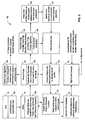
- FIG. 3 is a data flow diagram 150 further illustrating operation of the system of Figure 1 .
- air data inertial reference unit (ADIRU) 54 produces inertial position data which is enhanced with external GNSS measurements. More specifically, ADIRU 54 receives augmented GNSS data 152 as the GNSS references, in various embodiments, are enhanced by one or more of SBAS data and GBAS data. In receiving the augmented data 152, ADIRU 54 is enabled to combine augmented GNSS data 152 with the inertial data based on sensor data, for example, gyroscope and accelerometer data, to produce inertial/GNSS hybrid data and vehicle/earth reference parameters 154.
- sensor data for example, gyroscope and accelerometer data
- Airborne radar system 60 receives the inertial/GNSS hybrid data and vehicle/earth reference parameters 154 from ADIRU 54. Radar 60 produces a high resolution scan 160 of the terrain/airport environment off the nose of the air vehicle.
- the high resolution scan 160 has at least two functions. In one function, the data from the high resolution scan 160 is provided to a set of display driver algorithms 162 to provide a two dimensional image of the terrain/airport environment for display on one or more cockpit instruments, such as display 62, shown in Figure 1 .
- An example of such a display, as illustrated in Figure 3 is an electronic horizontal situation display.
- the data from the high resolution scan 160 is integrated with a database of airport radar signatures 164 having radar signature features stored within that have sufficient detail to allow the implementation of automatic image correlation using edge detection, scene matching or similar "fingerprinting" techniques.
- One utilization of this second function is to confirm identification of the airport 166.
- unique features 168 in the radar scan data against these features in the database of airport radar signatures 164 e.g., precise three dimensional locations of features exhibiting a specific radar signature, sometime referred to as reference points
- a location of the air vehicle can be determined.
- Specific radar features are then selected for use in distance measuring algorithms 170.
- Distance to the items providing the specific radar features are then used to calculate a position 172 of the air vehicle.
- pattern matching techniques ensure the recognition of these unique reference points, which are then used in the precision geolocation algorithms to determine air vehicle position in order to validate the inertial reference positioning data as radar based position data is compared 174 to ADIRU position data.
- System 50 (shown in Figure 1 ) utilizes published instrument approach procedures for each airport and runway which system 50 utilizes to perform approach path calculations 176 used for landing.
- these instrument approach procedures are an extension of current airport and runway databases that incorporated in known flight management computer systems.
- system 50 and data flow diagram 150 published approach, landing and rollout path information is fed from flight management systems to flight control computer 80.
- System 50 is then able to calculate and monitor the approach path 176 being flown and generate error signals, specifically synthesized glide slope and localizer error signals that are proportional to the amount of deviation from a defined path for landing of the air vehicle.
- These synthesized error signals mimic those glide slope and localizer signals provided by a conventional ILS and are used by flight control computer 80 to adjust the air vehicle flight controls to reduce the synthesized glide slope and localizer error signals, which is an indication that the air vehicle is on the desired approach path to the airport and/or airport runway.
- the radar image of the landing runway and surrounding airport environment is available for display as an overlay on the cockpit electronic horizontal situational or similar display.
- System 50 is a system that incorporates a process of using an airborne radar based sensor system to identify unique airport features and their radar signatures, and use the identified features to measure distances between the aircraft sensor (radar) and the three dimensional geolocations of the identified airport features.
- These identified features include one or more of runway edges, intersections of runways and taxiways, runway or approach lighting fixtures, radar corner reflectors or similar objects located such that their unique signatures and geolocations can be measured with sufficient precision to refine and validate the accuracy and integrity of the inertial reference or GNSS/inertial reference hybrid positioning data calculated by
- the inertial data source may comprise GNSS data augmented with data from at least one of a satellite based augmentation system or a ground based augmentation system.
- the satellite based augmentation system may comprise a wide area augmentation system and the ground based augmentation system comprises a local area augmentation system.
- the processing device may be programmed to match features within scan data received from said radar to features within said database utilizing at least one of image correlation, edge detection, and scene matching algorithms.
- the database may include approach, landing, and rollout path information for approach and landing areas, wherein said processing device is configured to generate at least one of glide slope error signals and localizer error signals proportional to the amount of deviation between the position of the air vehicle and an air vehicle position defined in the approach, landing, and rollout path information.
Landscapes
- Engineering & Computer Science (AREA)
- Radar, Positioning & Navigation (AREA)
- Remote Sensing (AREA)
- Physics & Mathematics (AREA)
- General Physics & Mathematics (AREA)
- Computer Networks & Wireless Communication (AREA)
- Aviation & Aerospace Engineering (AREA)
- Electromagnetism (AREA)
- Automation & Control Theory (AREA)
- Traffic Control Systems (AREA)
- Navigation (AREA)
Description
- This invention relates generally to aircraft approach and landing procedures, and more specifically to methods and systems for radar aided aircraft positioning for approaches and landings.
- Conventional instrument landing systems (ILS) utilize received localizer and glide slope transmissions to help guide an aircraft to properly approach an aircraft landing area, for example, a runway of an airport. The localizer signal provides azimuth, or lateral, information to be received by the ILS for use in guiding the aircraft to the centerline of the runway. The localizer signal includes radial information for a single course; the runway heading. The glide slope signal is the signal that provides vertical guidance to the aircraft during an ILS approach. A standard glide-slope path is 3° downhill to the approach-end of the runway.
- A decision height for an ILS approach is a point on the glide slope where a decision must be made to either continue the landing or execute a missed approach. In part, ILS systems have been categorized as follows: Category I ILS procedures have decision heights of not less than 200 feet and visibility minima not less than 800m (one-half mile), Category II ILS procedures have decision heights of not less than 100 feet and visibility minima not less than 400m (one-quarter mile), and one embodiment of Category III ILS procedures have decision heights of not less than 50 feet and visibility minima not less than 200m (one-eighth mile). Other Category III ILS procedures include a zero decision height. Category III ILS are subcategorized as IIIa, IIIb, and IIIc based on varying visibilities and decision heights. Categorization of ILS systems are based in part on the quality of the radio signals being transmitted.
- As can be deduced from the above, the better the quality of the ILS signals, the higher the categorization with the best being Category IIIc and the worst
- Other examples of prior art devices can be found disclosed in
US-B1-6512976 . - As can be deduced from the above, the better the quality of the ILS signals, the higher the categorization with the best being Category IIIc and the worst being Category I. For a pilot to be able to make an approach to a runway in bad weather, the weather has to be at or above certain conditions depending on the category of the ILS. If the weather is below the categorization of the ILS, the pilot has to revert to a holding pattern hoping that the weather improves to the capability of the ILS or divert to land elsewhere. No approach can be made to airports where the environments is below the ILS categorization.
- Not all runway ends support Category III landings. For a variety of reasons, ILS systems certified to Category III or even Category II supporting certain aircraft approaches are unfeasible or impractical.
- The present invention solves the problems associated with the prior art by providing an approach and landing system and method for an air vehicle, as defined in the claims.
-
-
Figure 1 is a block diagram of a system incorporating a radar that monitors integrity of GPS and inertial system position determinations. -
Figure 2 is a flowchart illustrating a method for radar aided positioning of an air vehicle for approach and landing. -
Figure 3 is a data flow diagram for the system ofFigure 1 and method ofFigure 2 . - The herein described methods and systems synthesize glide slope and azimuth (localizer) data equivalent to that of a category III instrument landing system by using a radar system to validate, refine the accuracy of, and ensure the integrity of the aircraft positioning data provided by GPS and inertial reference systems.
-
Figure 1 is a block diagram of asystem 50 which utilizes radar data for approach and landing of an air vehicle.System 50 includes a Global Navigation Satellite System (GNSS)receiver 52 providing positioning and timing data to an air data inertial reference unit (ADIRU) 54. ADIRU 54 receives data from one or moreinertial sensors 56, for example, accelerometers and gyroscopes enabling ADIRU 54 to estimate a position of the vehicle in which it is installed. - In one embodiment, GNSS
receiver 52 is augmented with one or more of a space based augmentation system (SBAS) and a ground based augmentation system (GBAS), as further described below. GNSS, of which the global positioning system (GPS) is one example, is a satellite-based navigation system made up of a network of satellites placed into orbit. GNSSs work anywhere and in any weather conditions. The satellites circle the earth in a very precise orbit and transmit signal information to earth. The GNSSreceiver 52 compares the time a signal was transmitted by a satellite with the time it was received. The time difference tells the GNSS receiver how far it is from the satellite. Using time difference data from several satellites, the receiver is capable of determining it's position. GNSS receivers (e.g., GNSS receiver 52) take the information received from the satellites and use triangulation to calculate an exact location of the receiver. - However, there are sources of inaccuracy when utilizing GNSS to determine a position. The satellite signal slows as it passes through the ionosphere and troposphere, though the GNSS is configured to calculate an average amount of delay to partially correct for this type of error. Multipath GNSS signals occur when the GNSS signal is reflected off objects before it reaches the receiver, increasing the travel time of the signal. A clock of the GNSS receiver is not as accurate as the atomic clocks onboard the GNSS satellites. Ephemeris errors are inaccuracies in the satellite's reported location. The number of satellites from which signals are being received also has an impact on the accuracy of the reported position. The more satellites a GNSS receiver can receive signals from, the better the accuracy in the reported position.
- Satellite based augmentation systems (SBASs), of which the wide area augmentation system (WAAS) is one example, include a number of dispersed ground reference stations that monitor GNSS satellite data. In one embodiment, a smaller number of master stations collect data from the reference stations and create a GNSS correction message. The correction message provides adjustment data for GNSS satellite orbit and clock drift in addition to signal delays caused by the atmosphere and ionosphere. The correction message from each master station is broadcast through one or more geostationary satellites which are fixed in position over the equator. The correction message is in a format that is compatible with basic GNSS signal structure, therefore, any SBAS-enabled GNSS receiver is capable of receiving and utilizing the correction message.
- Ground based augmentation systems (GBASs), of which local area augmentation system (LAAS) is one example, are based on a single GNSS reference station facility located on the property of the airport being serviced. This facility has three or more (redundant) reference receivers that independently measure GNSS satellite pseudorange and carrier phase and generate differential carrier-smoothed-code corrections that are eventually broadcast to a user (e.g., the aircraft attempting to land). The corrections typically include safety and approach-geometry information which allows users within forty-five kilometers of the GBAS ground station to perform GNSS-based position fixes with 0.5-meter (95%) accuracy and to perform all civil flight operations up to non-precision approach.
- Still referring to
Figure 1 ,system 50 includes aradar system 60 which is configured to output radar scan data to adisplay 62 which displays the radar scan data as an image, for example, for viewing by a pilot or navigator. Radar scan data as well as position data as determined by ADIRU 54 is output to aflight management system 64, in one embodiment. As further described below,system 50 includes aradar signature database 70 and adatabase 72 of information relating to approach, landing, and rollout information to be utilized in the landing of air vehicles.Databases flight management system 64.Flight management system 64, as further described, is programmed to utilize data from ADIRU 54, data fromradar 60 and data fromdatabases flight control computer 80 to adjust the flight path of the air vehicle. -
Figure 2 is aflowchart 100 illustrating a method for radar aided positioning of an air vehicle for approach and landing. The method includes integrating 102 GNSS data and inertial data to calculate a position of the air vehicle, scanning 104 the environment forward of the vehicle with a radar, producing a scan of the terrain and airport environment forward of the air vehicle. A database of terrain features and their radar signatures are accessed 106 based on the calculated position of the air vehicle. Features in the radar scan data are matched 108 to the radar signatures in the database to determine an actual position of the air vehicle, and glide slope and localizer signals are synthesized 110 for the approach and landing based on the determined actual position. As described above with respect toFigure 1 , in one embodiment, GNSS data is combined with at least one of SBAS data and GBAS data. - To match the features in the radar scan data to the radar signatures in the database, at least one of image correlation, edge detection, and scene matching algorithms to recognize reference points are utilized. Reference points are selected which may include objects that have radar signatures and geolocations whose positions can be precisely measured, and
flight management system 64 utilizes the reference point measurements from theradar 60 to validate the integrated GNSS data and inertial data as to the position of the air vehicle. At least a portion of the reference points are three dimensional geolocations. In a specific embodiment, data fromradar 60 is also overlaid an a radar image of the approach and landing area on a electronic horizontal situational display (e.g., display 62). - To synthesize the glide slope and localizer signals, in one embodiment,
flight management system 64 accesses published approach, landing, and rollout path information for the approach and landing area indatabase 72 and generates glide slope and localizer error signals that are proportional to the amount of deviation between the determined actual position of the aircraft and aircraft positions as defined in the approach, landing, and rollout path information. These error signals are utilized byflight control computer 80 to adjust a flight path of the air vehicle. - By matching features in the radar image to the radar signatures in
database 70 enables determining of the distance between the air vehicle and at least one of the features in the radar image, allowing determination of an actual position of the air vehicle. Devices that might typically be included withindatabase 70 include radar signatures of one or more of runway edges, intersections of runways and taxiways, runway of approach area lighting fixtures, radar corner reflectors. -
Figure 3 is a data flow diagram 150 further illustrating operation of the system ofFigure 1 . As described, in one embodiment, air data inertial reference unit (ADIRU) 54 produces inertial position data which is enhanced with external GNSS measurements. More specifically,ADIRU 54 receives augmentedGNSS data 152 as the GNSS references, in various embodiments, are enhanced by one or more of SBAS data and GBAS data. In receiving theaugmented data 152,ADIRU 54 is enabled to combineaugmented GNSS data 152 with the inertial data based on sensor data, for example, gyroscope and accelerometer data, to produce inertial/GNSS hybrid data and vehicle/earth reference parameters 154. -
Airborne radar system 60 receives the inertial/GNSS hybrid data and vehicle/earth reference parameters 154 fromADIRU 54.Radar 60 produces ahigh resolution scan 160 of the terrain/airport environment off the nose of the air vehicle. Thehigh resolution scan 160 has at least two functions. In one function, the data from thehigh resolution scan 160 is provided to a set ofdisplay driver algorithms 162 to provide a two dimensional image of the terrain/airport environment for display on one or more cockpit instruments, such asdisplay 62, shown inFigure 1 . An example of such a display, as illustrated inFigure 3 is an electronic horizontal situation display. - In a second function, the data from the
high resolution scan 160 is integrated with a database ofairport radar signatures 164 having radar signature features stored within that have sufficient detail to allow the implementation of automatic image correlation using edge detection, scene matching or similar "fingerprinting" techniques. One utilization of this second function is to confirm identification of theairport 166. Additionally, by matchingunique features 168 in the radar scan data against these features in the database of airport radar signatures 164 (e.g., precise three dimensional locations of features exhibiting a specific radar signature, sometime referred to as reference points) a location of the air vehicle can be determined. Specific radar features are then selected for use indistance measuring algorithms 170. Distance to the items providing the specific radar features are then used to calculate aposition 172 of the air vehicle. In this embodiment, pattern matching techniques ensure the recognition of these unique reference points, which are then used in the precision geolocation algorithms to determine air vehicle position in order to validate the inertial reference positioning data as radar based position data is compared 174 to ADIRU position data. - System 50 (shown in
Figure 1 ) utilizes published instrument approach procedures for each airport and runway whichsystem 50 utilizes to performapproach path calculations 176 used for landing. In one embodiment, these instrument approach procedures are an extension of current airport and runway databases that incorporated in known flight management computer systems. With regard tosystem 50 and data flow diagram 150, published approach, landing and rollout path information is fed from flight management systems toflight control computer 80.System 50 is then able to calculate and monitor theapproach path 176 being flown and generate error signals, specifically synthesized glide slope and localizer error signals that are proportional to the amount of deviation from a defined path for landing of the air vehicle. These synthesized error signals mimic those glide slope and localizer signals provided by a conventional ILS and are used byflight control computer 80 to adjust the air vehicle flight controls to reduce the synthesized glide slope and localizer error signals, which is an indication that the air vehicle is on the desired approach path to the airport and/or airport runway. - As described above, to provide confidence in the reliability and accuracy of using radar images to monitor and refine inertial system based position determinations, the radar image of the landing runway and surrounding airport environment is available for display as an overlay on the cockpit electronic horizontal situational or similar display.
-
System 50, as described above, is a system that incorporates a process of using an airborne radar based sensor system to identify unique airport features and their radar signatures, and use the identified features to measure distances between the aircraft sensor (radar) and the three dimensional geolocations of the identified airport features. These identified features include one or more of runway edges, intersections of runways and taxiways, runway or approach lighting fixtures, radar corner reflectors or similar objects located such that their unique signatures and geolocations can be measured with sufficient precision to refine and validate the accuracy and integrity of the inertial reference or GNSS/inertial reference hybrid positioning data calculated by The inertial data source may comprise GNSS data augmented with data from at least one of a satellite based augmentation system or a ground based augmentation system. - The satellite based augmentation system may comprise a wide area augmentation system and the ground based augmentation system comprises a local area augmentation system.
- The processing device may be programmed to match features within scan data received from said radar to features within said database utilizing at least one of image correlation, edge detection, and scene matching algorithms.
- The database may include approach, landing, and rollout path information for approach and landing areas, wherein said processing device is configured to generate at least one of glide slope error signals and localizer error signals proportional to the amount of deviation between the position of the air vehicle and an air vehicle position defined in the approach, landing, and rollout path information.
Claims (15)
- An approach and landing system (50) for an air vehicle comprising:an inertial data source (54) configured to provide a position of the air vehicle;a radar system (60) configured to scan the environment forward of the air vehicle;a database (72) of terrain features including a location for each terrain feature and a radar signature for each terrain feature stored in said database; anda processing device (64), said processing device programmed to match terrain features from a radar scan of the forward environment with the radar signatures of the terrain features in said database to monitor and refine the position of the air vehicle received from said inertial data source, said processing device programmed to synthesize a glide slope signal and a localizer signal for the approach and landing based on the refined air vehicle position.
- An approach and landing system (50) according to Claim 1 wherein said inertial data source (54) comprises GNSS data augmented with data from at least one of a satellite based augmentation system or a ground based augmentation system.
- An approach and landing system (50) according to Claim 2 wherein the satellite based augmentation system comprises a wide area augmentation system and the ground based augmentation system comprises a local area augmentation system.
- An approach and landing system (50) according to Claim 1 wherein said processing device (64) is programmed to match features within scan data received from said radar system (60) to features within said database (72) utilizing at least one of image correlation, edge detection, and scene matching algorithms.
- An approach and landing system (50) according to Claim 1 wherein said database (72) includes approach, landing, and rollout path information for approach and landing areas, wherein said processing device (64) is configured to generate glide slope error signals and localizer error signals proportional to the amount of deviation between the position of the air vehicle and an air vehicle position defined in the approach, landing, and rollout path information.
- An approach and landing system (50) according to Claim 5 further comprising a flight control computer (80) configured to utilize the glide slope error signals and localizer error signals to adjust a flight path of the air vehicle.
- An approach and landing system (50) according to Claim 1 further comprising a display (62), said system configured to utilize data from said radar system (60) to overlay a radar image of the approach and landing area on said display.
- An approach and landing system (50) according to Claim 7 wherein to refine a position of the air vehicle, said processing device (64) is configured to determine a distance between the air vehicle and one of the terrain feature in the radar image to determine an actual position of the air vehicle.
- An approach and landing system (50) according to Claim 1 wherein the terrain features in said database (72) comprise at least one of runway edges, intersections of runways and taxiways, runway of approach area lighting fixtures, and radar corner reflectors.
- A method (100) for radar aided positioning of an air vehicle for approach and landing, the method comprising:integrating global navigation satellite system (GNSS) data and inertial data to calculate a position of the air vehicle (102);performing a radar scan of an environment forward of the air vehicle (104);accessing a database of terrain features that includes locations of the terrain features and radar signatures of the terrain features (106);matching features in the radar scan with the radar signatures of the terrain features in the database to determine an actual position of the air vehicle (108); andsynthesizing glide slope and localizer signals for the approach and landing based on the determined actual position (110).
- A method according to Claim 10 wherein matching features in the radar scan with the radar signatures in the database comprises utilizing at least one of image correlation, edge detection, and scene matching algorithms to recognize reference points.
- A method according to Claim 11 further comprising:selecting as reference points objects having radar signatures and geolocations whose positions can be precisely measured; andutilizing reference point measurements to validate the integrated GNSS data and inertial data;wherein at least a portion of the reference points comprise three dimensional geolocations.
- A method according to Claim 10 wherein synthesizing glide slope and localizer signals comprises:accessing published approach, landing, and rollout path information for the approach and landing area;generating glide slope and localizer error signals proportional to the amount of deviation between the determined actual position of the aircraft and an aircraft position defined in the approach, landing, and rollout path information; andutilizing the error signals to adjust a flight path of the air vehicle.
- A method according to Claim 10 wherein matching terrain features from the radar scan to the radar signatures in the database comprises determining a distance between the air vehicle and at least one of the terrain features from the radar scan to determine an actual position of the air vehicle.
- A method according to Claim 10 wherein the radar signatures in the database include one or more radar signatures of runway edges, intersections of runways and taxiways, runway of approach area lighting fixtures, and radar corner reflectors.
Applications Claiming Priority (1)
| Application Number | Priority Date | Filing Date | Title |
|---|---|---|---|
| US11/419,595 US8160758B2 (en) | 2006-05-22 | 2006-05-22 | Methods and systems for radar aided aircraft positioning for approaches and landings |
Publications (2)
| Publication Number | Publication Date |
|---|---|
| EP1860456A1 EP1860456A1 (en) | 2007-11-28 |
| EP1860456B1 true EP1860456B1 (en) | 2016-09-14 |
Family
ID=38457882
Family Applications (1)
| Application Number | Title | Priority Date | Filing Date |
|---|---|---|---|
| EP07108535.1A Active EP1860456B1 (en) | 2006-05-22 | 2007-05-21 | Methods and systems for radar aided aircraft positioning for approaches and landings |
Country Status (3)
| Country | Link |
|---|---|
| US (1) | US8160758B2 (en) |
| EP (1) | EP1860456B1 (en) |
| CA (1) | CA2589308A1 (en) |
Families Citing this family (54)
| Publication number | Priority date | Publication date | Assignee | Title |
|---|---|---|---|---|
| US7739167B2 (en) | 1999-03-05 | 2010-06-15 | Era Systems Corporation | Automated management of airport revenues |
| US7667647B2 (en) | 1999-03-05 | 2010-02-23 | Era Systems Corporation | Extension of aircraft tracking and positive identification from movement areas into non-movement areas |
| US8203486B1 (en) | 1999-03-05 | 2012-06-19 | Omnipol A.S. | Transmitter independent techniques to extend the performance of passive coherent location |
| US7782256B2 (en) | 1999-03-05 | 2010-08-24 | Era Systems Corporation | Enhanced passive coherent location techniques to track and identify UAVs, UCAVs, MAVs, and other objects |
| US7570214B2 (en) | 1999-03-05 | 2009-08-04 | Era Systems, Inc. | Method and apparatus for ADS-B validation, active and passive multilateration, and elliptical surviellance |
| US7777675B2 (en) | 1999-03-05 | 2010-08-17 | Era Systems Corporation | Deployable passive broadband aircraft tracking |
| US7889133B2 (en) | 1999-03-05 | 2011-02-15 | Itt Manufacturing Enterprises, Inc. | Multilateration enhancements for noise and operations management |
| US8446321B2 (en) | 1999-03-05 | 2013-05-21 | Omnipol A.S. | Deployable intelligence and tracking system for homeland security and search and rescue |
| US7908077B2 (en) | 2003-06-10 | 2011-03-15 | Itt Manufacturing Enterprises, Inc. | Land use compatibility planning software |
| FR2888636B1 (en) * | 2005-07-13 | 2007-09-28 | Airbus France Sas | DEVICE FOR AIDING AN APPROACH WITH VERTICAL GUIDE FOR AN AIRCRAFT |
| US7965227B2 (en) | 2006-05-08 | 2011-06-21 | Era Systems, Inc. | Aircraft tracking using low cost tagging as a discriminator |
| FR2908904B1 (en) * | 2006-11-21 | 2009-02-06 | Airbus France Sa | AIRCRAFT DRIVING SYSTEM COMPRISING AERONAUTICAL DATABASE. |
| GB0801523D0 (en) * | 2008-01-28 | 2008-03-05 | Cambridge Silicon Radio Ltd | Integrated signal receiver |
| US20100188280A1 (en) * | 2009-01-23 | 2010-07-29 | Honeywell International Inc. | Systems and methods for determining location of an airborne vehicle using radar images |
| FR2947641B1 (en) | 2009-07-03 | 2012-01-13 | Airbus Operations Sas | METHOD FOR EVALUATING AN ERROR IN THE POSITIONING OF AN AIRCRAFT GENERATED BY AN ONBOARD POSITIONING SYSTEM |
| CN101702266B (en) * | 2009-10-30 | 2011-05-11 | 中国航空无线电电子研究所 | Double station approach guidance positioning system and application |
| IL202062A0 (en) * | 2009-11-11 | 2010-11-30 | Dror Nadam | Apparatus, system and method for self orientation |
| US8378891B2 (en) * | 2010-02-12 | 2013-02-19 | Broadcom Corporation | Method and system for optimizing quality and integrity of location database elements |
| US20110246002A1 (en) * | 2010-04-02 | 2011-10-06 | Cloudahoy Inc. | Systems and methods for aircraft flight tracking and analysis |
| US9159241B1 (en) * | 2011-04-15 | 2015-10-13 | The Boeing Company | Methods, systems, and apparatus for synthetic instrument landing system (SILS) |
| US9087450B2 (en) | 2011-05-17 | 2015-07-21 | Innovative Solutions And Support, Inc. | Upgraded flight management system and method of providing the same |
| US9709992B2 (en) | 2011-05-17 | 2017-07-18 | Innovative Solutions & Support, Inc. | Upgraded flight management system for autopilot control and method of providing the same |
| EP2639781A1 (en) * | 2012-03-14 | 2013-09-18 | Honda Motor Co., Ltd. | Vehicle with improved traffic-object position detection |
| US9097529B2 (en) * | 2012-07-12 | 2015-08-04 | Honeywell International Inc. | Aircraft system and method for improving navigation performance |
| US9139307B2 (en) | 2013-06-28 | 2015-09-22 | Honeywell International Inc. | Aircraft systems and methods for displaying runway lighting information |
| DE102013015892B4 (en) | 2013-09-25 | 2015-12-24 | Deutsches Zentrum für Luft- und Raumfahrt e.V. | Position determination of a vehicle on or above a planetary surface |
| US9483842B2 (en) | 2014-04-14 | 2016-11-01 | Vricon Systems Aktiebolag | Navigation based on at least one sensor and a three dimensional map |
| US9360321B2 (en) | 2014-04-14 | 2016-06-07 | Vricon Systems Aktiebolag | Navigation based on at least one sensor and a three dimensional map |
| US9886040B1 (en) * | 2014-09-24 | 2018-02-06 | Rockwell Collins, Inc. | System and method for platform alignment, navigation or targeting |
| EP3021306B1 (en) | 2014-11-14 | 2020-10-28 | Airbus Defence and Space GmbH | Automatic take-off and landing control device |
| ES2628035T3 (en) | 2014-11-28 | 2017-08-01 | Pildo Consulting, Sl | Device and procedure for the validation of flight procedures and verification for an aerial vehicle |
| EP3761144A1 (en) * | 2015-06-12 | 2021-01-06 | Innovative Solutions & Support, Inc. | Upgraded flight management system for autopilot control and method of providing the same |
| US9975648B2 (en) * | 2015-12-04 | 2018-05-22 | The Boeing Company | Using radar derived location data in a GPS landing system |
| US9836064B2 (en) * | 2016-03-02 | 2017-12-05 | The Boeing Company | Aircraft landing systems and methods |
| FR3054357B1 (en) * | 2016-07-21 | 2022-08-12 | Airbus Operations Sas | METHOD AND DEVICE FOR DETERMINING THE POSITION OF AN AIRCRAFT DURING AN APPROACH FOR A LANDING |
| CN106352872B (en) * | 2016-09-14 | 2019-11-08 | 北京理工大学 | A kind of unmanned plane autonomous navigation system and its air navigation aid |
| US10203693B2 (en) | 2016-11-01 | 2019-02-12 | The Boeing Company | Flight control system with synthetic inertial glideslope deviation and method of use |
| US10175694B2 (en) | 2016-11-01 | 2019-01-08 | The Boeing Company | Flight control system with synthetic inertial localizer deviation and method of use |
| US10089892B2 (en) | 2016-11-01 | 2018-10-02 | The Boeing Company | Flight control system with low-frequency instrument landing system localizer anomaly detection and method of use |
| EP3343172B1 (en) | 2017-01-03 | 2024-03-13 | iOnRoad Technologies Ltd. | Creation and use of enhanced maps |
| US10830873B2 (en) | 2017-01-06 | 2020-11-10 | Honeywell International Inc. | Synthesizer for radar sensing |
| US11035962B2 (en) | 2018-09-11 | 2021-06-15 | Honeywell International S.R.O. | Supplemental system for a satellite based approach during low visibility conditions |
| US11168986B2 (en) * | 2019-02-13 | 2021-11-09 | Rockwell Collins, Inc. | Navigation system and method |
| US11709819B2 (en) | 2020-09-30 | 2023-07-25 | International Business Machines Corporation | Validating test results using a blockchain network |
| FR3115895A1 (en) * | 2020-11-05 | 2022-05-06 | Airbus Operations (S.A.S.) | Aircraft landing aid system and method. |
| US11914053B2 (en) | 2021-01-11 | 2024-02-27 | Honeywell International Inc. | Vehicle location accuracy enhancement system |
| CN113341444A (en) * | 2021-06-30 | 2021-09-03 | 中国船舶重工集团公司第七一三研究所 | Airport luggage intelligent omnidirectional transmission platform positioning navigation system and method |
| CN113671455A (en) * | 2021-09-07 | 2021-11-19 | 辽宁工程技术大学 | Simulation analysis method for geometric positioning accuracy of medium and high orbit SAR (synthetic aperture radar) satellite |
| WO2023044166A2 (en) * | 2021-09-20 | 2023-03-23 | DC-001, Inc. | Systems and methods for communicating with and controlling vehicles |
| ES2943390A1 (en) * | 2021-12-10 | 2023-06-12 | Z Point Navigator S L | AIRCRAFT POSITIONING METHOD, LOCATION SYSTEM AND COMPUTER PROGRAM PROVIDING SUCH METHOD (Machine-translation by Google Translate, not legally binding) |
| CN114509073B (en) * | 2022-01-28 | 2024-03-26 | 中国商用飞机有限责任公司 | Course signal processing method and device, storage medium and aircraft |
| CN114485677B (en) * | 2022-04-14 | 2022-06-24 | 中国民用航空总局第二研究所 | Visual range coverage analysis method for civil aviation navigation equipment with variable height by combining flight track |
| FR3139654A1 (en) * | 2022-09-13 | 2024-03-15 | Safran Electronics & Defense | Navigation method and device for an aircraft, system, aircraft, computer program and associated information carrier |
| CN117872259B (en) * | 2024-03-13 | 2024-06-11 | 天津七六四通信导航技术有限公司 | Method and system for processing sliding monitoring signal in instrument landing system |
Family Cites Families (23)
| Publication number | Priority date | Publication date | Assignee | Title |
|---|---|---|---|---|
| US4866450A (en) * | 1986-05-15 | 1989-09-12 | Sundstrand Data Control, Inc. | Advanced instrument landing system |
| US6195609B1 (en) * | 1993-09-07 | 2001-02-27 | Harold Robert Pilley | Method and system for the control and management of an airport |
| US6006158A (en) | 1993-09-07 | 1999-12-21 | H. R. Pilley | Airport guidance and safety system incorporating lighting control using GNSS compatible methods |
| US5657009A (en) * | 1991-10-31 | 1997-08-12 | Gordon; Andrew A. | System for detecting and viewing aircraft-hazardous incidents that may be encountered by aircraft landing or taking-off |
| US5361212A (en) | 1992-11-02 | 1994-11-01 | Honeywell Inc. | Differential GPS landing assistance system |
| US5714948A (en) * | 1993-05-14 | 1998-02-03 | Worldwide Notifications Systems, Inc. | Satellite based aircraft traffic control system |
| US5654890A (en) * | 1994-05-31 | 1997-08-05 | Lockheed Martin | High resolution autonomous precision approach and landing system |
| ATE244895T1 (en) * | 1996-05-14 | 2003-07-15 | Honeywell Int Inc | AUTONOMOUS LANDING GUIDANCE SYSTEM |
| US6094607A (en) | 1998-11-27 | 2000-07-25 | Litton Systems Inc. | 3D AIME™ aircraft navigation |
| US5952961A (en) * | 1998-01-30 | 1999-09-14 | Trimble Navigation Limited | Low observable radar augmented GPS navigation system |
| US6233522B1 (en) | 1998-07-06 | 2001-05-15 | Alliedsignal Inc. | Aircraft position validation using radar and digital terrain elevation database |
| US6639541B1 (en) * | 2000-08-29 | 2003-10-28 | The United States Of America As Represented By The Secretary Of The Navy | Device and method for detecting, measuring, and reporting low-level interference at a receiver |
| US6930617B2 (en) | 2000-11-08 | 2005-08-16 | Toyota Motor Sales, U.S.A., Inc. | Methods and apparatus for airspace navigation |
| US6405107B1 (en) * | 2001-01-11 | 2002-06-11 | Gary Derman | Virtual instrument pilot: an improved method and system for navigation and control of fixed wing aircraft |
| US6529820B2 (en) * | 2001-04-10 | 2003-03-04 | Ion Tomescu | System and method for determining the 3D position of aircraft, independently onboard and on the ground, for any operation within a “gate-to-gate” concept |
| US6512976B1 (en) | 2001-04-27 | 2003-01-28 | Honeywell International Inc. | Method and system for terrain aided navigation |
| US6571155B2 (en) * | 2001-07-02 | 2003-05-27 | The Boeing Company | Assembly, computer program product and method for displaying navigation performance based flight path deviation information |
| US6492934B1 (en) * | 2001-08-06 | 2002-12-10 | Rockwell Collins | Method of deriving ground speed for descending aircraft |
| US7089092B1 (en) | 2002-07-18 | 2006-08-08 | Rockwell Collins, Inc. | Airborne system and method for improving the integrity of electronic landing aids |
| US7024287B2 (en) | 2003-07-25 | 2006-04-04 | Honeywell International Inc. | Flight management computer lateral route recapture |
| US7373223B2 (en) * | 2004-02-13 | 2008-05-13 | The Boeing Company | Global navigation satellite system landing systems and methods |
| US7479925B2 (en) * | 2005-03-23 | 2009-01-20 | Honeywell International Inc. | Airport runway collision avoidance system and method |
| US7693620B2 (en) * | 2005-05-31 | 2010-04-06 | The Boeing Company | Approach guidance system and method for airborne mobile platform |
-
2006
- 2006-05-22 US US11/419,595 patent/US8160758B2/en active Active
-
2007
- 2007-05-18 CA CA 2589308 patent/CA2589308A1/en not_active Abandoned
- 2007-05-21 EP EP07108535.1A patent/EP1860456B1/en active Active
Also Published As
| Publication number | Publication date |
|---|---|
| EP1860456A1 (en) | 2007-11-28 |
| CA2589308A1 (en) | 2007-11-22 |
| US20100256840A1 (en) | 2010-10-07 |
| US8160758B2 (en) | 2012-04-17 |
Similar Documents
| Publication | Publication Date | Title |
|---|---|---|
| EP1860456B1 (en) | Methods and systems for radar aided aircraft positioning for approaches and landings | |
| US7373223B2 (en) | Global navigation satellite system landing systems and methods | |
| US5646857A (en) | Use of an altitude sensor to augment availability of GPS location fixes | |
| Parkinson et al. | Progress in astronautics and aeronautics: Global positioning system: Theory and applications | |
| RU2602833C2 (en) | Near-field navigation system | |
| US10094667B2 (en) | Autonomous precision navigation | |
| US5504492A (en) | Look ahead satellite positioning system position error bound monitoring system | |
| US8818582B2 (en) | Method and system for determining the position of an aircraft during its approach to a landing runway | |
| US6161062A (en) | Aircraft piloting aid system using a head-up display | |
| US5952961A (en) | Low observable radar augmented GPS navigation system | |
| US7098846B2 (en) | All-weather precision guidance and navigation system | |
| US20080119970A1 (en) | Precision Approach Guidance System And Associated Method | |
| WO2001011383A1 (en) | Method and system for creating an approach to a position on the ground from a location above the ground | |
| US7054739B2 (en) | Radio navigation system | |
| US10514467B2 (en) | Up sampling reference station data | |
| KR20170048087A (en) | Aircraft Landing Apparatus Using GNSS and SBAS Singals, and Control Method Thereof | |
| US5910788A (en) | Predictive approach integrity | |
| Salih et al. | The suitability of GPS receivers update rates for navigation applications | |
| KR100879799B1 (en) | A landing guide system for a aircraft using a gps receiver | |
| RU2018111105A (en) | A comprehensive way to navigate an aircraft | |
| US20050143872A1 (en) | Aircraft gps instrumentation system and relative method | |
| JPH09218038A (en) | Method for positioning highly accurate survey control mark utilizing satellite | |
| CN118730102A (en) | Device and system for estimating the position and speed of an aircraft during an approach phase | |
| Kubiš et al. | 24. Position Reference System for Flight Inspection Aircraft | |
| Butzmühlen et al. | Ensuring the GNSS Onboard Integrity Function Under Adverse Conditions: Feasibility and Flight Test Results |
Legal Events
| Date | Code | Title | Description |
|---|---|---|---|
| PUAI | Public reference made under article 153(3) epc to a published international application that has entered the european phase |
Free format text: ORIGINAL CODE: 0009012 |
|
| AK | Designated contracting states |
Kind code of ref document: A1 Designated state(s): AT BE BG CH CY CZ DE DK EE ES FI FR GB GR HU IE IS IT LI LT LU LV MC MT NL PL PT RO SE SI SK TR |
|
| AX | Request for extension of the european patent |
Extension state: AL BA HR MK YU |
|
| 17P | Request for examination filed |
Effective date: 20080521 |
|
| 17Q | First examination report despatched |
Effective date: 20080619 |
|
| AKX | Designation fees paid |
Designated state(s): FR |
|
| REG | Reference to a national code |
Ref country code: DE Ref legal event code: 8566 |
|
| APBK | Appeal reference recorded |
Free format text: ORIGINAL CODE: EPIDOSNREFNE |
|
| APBN | Date of receipt of notice of appeal recorded |
Free format text: ORIGINAL CODE: EPIDOSNNOA2E |
|
| APBR | Date of receipt of statement of grounds of appeal recorded |
Free format text: ORIGINAL CODE: EPIDOSNNOA3E |
|
| APAF | Appeal reference modified |
Free format text: ORIGINAL CODE: EPIDOSCREFNE |
|
| APBX | Invitation to file observations in appeal sent |
Free format text: ORIGINAL CODE: EPIDOSNOBA2E |
|
| APBT | Appeal procedure closed |
Free format text: ORIGINAL CODE: EPIDOSNNOA9E |
|
| RAP1 | Party data changed (applicant data changed or rights of an application transferred) |
Owner name: HONEYWELL INTERNATIONAL INC. |
|
| GRAP | Despatch of communication of intention to grant a patent |
Free format text: ORIGINAL CODE: EPIDOSNIGR1 |
|
| INTG | Intention to grant announced |
Effective date: 20160506 |
|
| GRAS | Grant fee paid |
Free format text: ORIGINAL CODE: EPIDOSNIGR3 |
|
| GRAA | (expected) grant |
Free format text: ORIGINAL CODE: 0009210 |
|
| AK | Designated contracting states |
Kind code of ref document: B1 Designated state(s): FR |
|
| REG | Reference to a national code |
Ref country code: FR Ref legal event code: PLFP Year of fee payment: 11 |
|
| PLBE | No opposition filed within time limit |
Free format text: ORIGINAL CODE: 0009261 |
|
| STAA | Information on the status of an ep patent application or granted ep patent |
Free format text: STATUS: NO OPPOSITION FILED WITHIN TIME LIMIT |
|
| 26N | No opposition filed |
Effective date: 20170615 |
|
| REG | Reference to a national code |
Ref country code: FR Ref legal event code: PLFP Year of fee payment: 12 |
|
| P01 | Opt-out of the competence of the unified patent court (upc) registered |
Effective date: 20230525 |
|
| PGFP | Annual fee paid to national office [announced via postgrant information from national office to epo] |
Ref country code: FR Payment date: 20240527 Year of fee payment: 18 |