EP3667289A2 - Particle number counting device and particle number counting method - Google Patents
Particle number counting device and particle number counting method Download PDFInfo
- Publication number
- EP3667289A2 EP3667289A2 EP19194212.7A EP19194212A EP3667289A2 EP 3667289 A2 EP3667289 A2 EP 3667289A2 EP 19194212 A EP19194212 A EP 19194212A EP 3667289 A2 EP3667289 A2 EP 3667289A2
- Authority
- EP
- European Patent Office
- Prior art keywords
- number counting
- particle number
- resistance element
- fluid resistance
- pressure
- Prior art date
- Legal status (The legal status is an assumption and is not a legal conclusion. Google has not performed a legal analysis and makes no representation as to the accuracy of the status listed.)
- Withdrawn
Links
- 239000002245 particle Substances 0.000 title claims abstract description 87
- 238000000034 method Methods 0.000 title claims description 4
- 239000012530 fluid Substances 0.000 claims abstract description 46
- 238000011144 upstream manufacturing Methods 0.000 claims description 20
- 238000009530 blood pressure measurement Methods 0.000 claims description 4
- 230000000694 effects Effects 0.000 abstract description 5
- 238000009833 condensation Methods 0.000 description 10
- 230000005494 condensation Effects 0.000 description 10
- 239000013618 particulate matter Substances 0.000 description 9
- LRHPLDYGYMQRHN-UHFFFAOYSA-N N-Butanol Chemical compound CCCCO LRHPLDYGYMQRHN-UHFFFAOYSA-N 0.000 description 2
- QAOWNCQODCNURD-UHFFFAOYSA-N Sulfuric acid Chemical compound OS(O)(=O)=O QAOWNCQODCNURD-UHFFFAOYSA-N 0.000 description 2
- 150000001298 alcohols Chemical class 0.000 description 2
- 238000001704 evaporation Methods 0.000 description 2
- 230000008020 evaporation Effects 0.000 description 2
- 238000010438 heat treatment Methods 0.000 description 2
- 238000005259 measurement Methods 0.000 description 2
- 230000010349 pulsation Effects 0.000 description 2
- 238000002485 combustion reaction Methods 0.000 description 1
- 238000001816 cooling Methods 0.000 description 1
- 230000007423 decrease Effects 0.000 description 1
- 230000003247 decreasing effect Effects 0.000 description 1
- 238000010790 dilution Methods 0.000 description 1
- 239000012895 dilution Substances 0.000 description 1
- 239000000428 dust Substances 0.000 description 1
- 238000004868 gas analysis Methods 0.000 description 1
- 239000003595 mist Substances 0.000 description 1
- 238000012986 modification Methods 0.000 description 1
- 230000004048 modification Effects 0.000 description 1
- 238000001089 thermophoresis Methods 0.000 description 1
Images


Classifications
-
- G—PHYSICS
- G01—MEASURING; TESTING
- G01N—INVESTIGATING OR ANALYSING MATERIALS BY DETERMINING THEIR CHEMICAL OR PHYSICAL PROPERTIES
- G01N15/00—Investigating characteristics of particles; Investigating permeability, pore-volume or surface-area of porous materials
- G01N15/06—Investigating concentration of particle suspensions
- G01N15/065—Investigating concentration of particle suspensions using condensation nuclei counters
-
- G—PHYSICS
- G01—MEASURING; TESTING
- G01M—TESTING STATIC OR DYNAMIC BALANCE OF MACHINES OR STRUCTURES; TESTING OF STRUCTURES OR APPARATUS, NOT OTHERWISE PROVIDED FOR
- G01M15/00—Testing of engines
- G01M15/04—Testing internal-combustion engines
- G01M15/10—Testing internal-combustion engines by monitoring exhaust gases or combustion flame
- G01M15/102—Testing internal-combustion engines by monitoring exhaust gases or combustion flame by monitoring exhaust gases
-
- G—PHYSICS
- G01—MEASURING; TESTING
- G01M—TESTING STATIC OR DYNAMIC BALANCE OF MACHINES OR STRUCTURES; TESTING OF STRUCTURES OR APPARATUS, NOT OTHERWISE PROVIDED FOR
- G01M15/00—Testing of engines
- G01M15/04—Testing internal-combustion engines
- G01M15/10—Testing internal-combustion engines by monitoring exhaust gases or combustion flame
- G01M15/102—Testing internal-combustion engines by monitoring exhaust gases or combustion flame by monitoring exhaust gases
- G01M15/106—Testing internal-combustion engines by monitoring exhaust gases or combustion flame by monitoring exhaust gases using pressure sensors
-
- G—PHYSICS
- G01—MEASURING; TESTING
- G01N—INVESTIGATING OR ANALYSING MATERIALS BY DETERMINING THEIR CHEMICAL OR PHYSICAL PROPERTIES
- G01N15/00—Investigating characteristics of particles; Investigating permeability, pore-volume or surface-area of porous materials
- G01N2015/0042—Investigating dispersion of solids
- G01N2015/0046—Investigating dispersion of solids in gas, e.g. smoke
Definitions
- the present invention relates to a particle number counting device and a particle number counting method.
- a particle number counter known as a condensation particle counter (CPC) is used as a device that is capable of precisely counting particulate matter (i.e., of counting a particulate number (PN)) contained in extracted exhaust gas.
- CPC condensation particle counter
- this condensation particle counter operates by causing particulate matter to pass through a supersaturated alcohol atmosphere so that the diameter thereof grows to a large size, and then using laser light to count the particulate matter that is then expelled through a slit.
- a differential pressure flow meter that is used to adjust a flow rate of an introduced gas is provided in the condensation particle counter. This differential pressure flow meter measures a flow rate by detecting a differential pressure between an upstream side of a critical orifice and a downstream side thereof.
- Patent document 1 Japanese Unexamined Patent Application ( JP-A) No. 2012-127773
- the present invention was conceived in order to solve the above-described problem, and it is a principal object thereof to reduce the effects on particle number counting from variations in the outside air pressure.
- a particle number counting device is characterized in being provided with an exhaust gas processing unit that performs predetermined processing on exhaust gas, a particle number counting unit that counts a number of particles contained in exhaust gas that has passed through the exhaust gas processing unit, a fluid resistance element that is provided downstream from the particle number counting unit, a suction pump that is provided downstream from the fluid resistance element, a gas supply path that is connected to a flow path between the fluid resistance element and the suction pump, and that supplies gas to a downstream side of the fluid resistance element, and a flow rate adjustment unit that is provided on the gas supply path, and that adjusts a flow rate of the gas that is supplied to the downstream side of the fluid resistance element.
- a flow rate adjustment unit is provided on a gas supply path that introduces a gas to a downstream side of a fluid resistance element, by adjusting the flow rate of the gas supplied to the downstream side of the fluid resistance element in accordance with variations in the outside air pressure, it is possible to reduce variations in the flow rate flowing through the fluid resistance element. As a result, even if there are variations in the outside air pressure, it is still possible to perform accurate particle number counting.
- a pressure sensor that measures a differential pressure between a pressure on the upstream side of the fluid resistance element and a pressure on the downstream side thereof, or a pressure on the upstream side of the fluid resistance element, or an outside air pressure, and a control unit that controls the flow rate adjustment unit based on pressure measurements made by the pressure sensor.
- control unit controls the flow rate adjustment unit such that the differential pressure between the pressure on the upstream side of the fluid resistance element and the pressure on the downstream side thereof is within a predetermined range
- the gas supply path be connected to the flow path between the exhaust gas processing unit and the particle number counting unit via a buffer tank.
- a gas discharge path that is connected to the flow path between the exhaust gas processing unit and the particle number counting unit, an exhaust pump that is provided on the gas discharge path, and a buffer tank that is provided on the gas discharge path on the upstream side of the exhaust pump.
- the gas supply path be connected to the buffer tank.
- a particle number counting method employs a particle number counting device provided with an exhaust gas processing unit that performs predetermined processing on exhaust gas, a particle number counting unit that counts a number of particles contained in exhaust gas that has passed through the exhaust gas processing unit, a fluid resistance element that is provided downstream from the particle number counting unit, a suction pump that is provided downstream from the fluid resistance element, a gas supply path that is connected to a flow path between the fluid resistance element and the suction pump, and supplies gas to a downstream side of the fluid resistance element, and a flow rate adjustment unit that is provided on the gas supply path, and adjusts a flow rate of the gas that is supplied to the downstream side of the fluid resistance element, and it is desirable that the flow rate adjustment unit be controlled based on a differential pressure between a pressure on the upstream side of the fluid resistance element and a pressure on the downstream side thereof, or on a pressure on the upstream side of the fluid resistance element, or on an outside air pressure.
- a particle number counting device 100 of the present embodiment counts particulate matter (i.e., counts a particulate number (PN), hereinafter referred to as a 'particle number') contained in exhaust gas.
- the exhaust gas is discharged from an exhaust pipe that is connected to an internal combustion engine, and is diluted using a constant volume sampler (CVS) or the like. A portion thereof is then extracted and introduced into the particle number counting device 100.
- CVS constant volume sampler
- the exhaust gas it is also possible for the exhaust gas to be diluted using a dilution gas separately from the CVS, or for the exhaust gas to be left undiluted.
- the particle number counting device 100 is provided with an exhaust gas processing unit 2 that performs predetermined processing on exhaust gas diluted using a CVS or the like, a particle number counting unit 3 that counts a number of particles contained in exhaust gas that has passed through the exhaust gas processing unit 2, a differential pressure flow meter 4 that is provided downstream from the particle number counting unit 3, a suction pump 5 that is provided downstream from the differential pressure flow meter 4, a gas supply path 6 that is connected to a flow path between the differential pressure flow meter 4 and the suction pump 5, and supplies gas to a downstream side of the differential pressure flow meter 4, a flow rate adjustment unit 7 that is provided on the gas supply path 6, and adjusts a flow rate of the gas that is supplied to the downstream side of the differential pressure flow meter 4, and a control unit 8 that controls the flow rate adjustment unit 7.
- an exhaust gas processing unit 2 that performs predetermined processing on exhaust gas diluted using a CVS or the like
- a particle number counting unit 3 that counts a number of particles contained in exhaust gas that has passed through the exhaust gas processing
- the exhaust gas processing unit 2 is a volatile particle remover (VPR) that removes volatile particles that are formed by sulfuric acid mist and a soluble organic fraction (SOF) contained in the exhaust gas.
- VPR volatile particle remover
- This volatile particle remover 2 has a heat diluter 21, an evaporation tube 22, and a cold diluter 23.
- the exhaust gas is diluted, for example, by a factor of between 10 and 200 by the heat diluter 21 which has a predetermined first heating temperature (for example, 150 ⁇ 400 °C), and volatile particles that have already been formed are gasified by the evaporation tube 22 which has a second heating temperature (for example, 300 ⁇ 400 °C) provided further downstream.
- the exhaust gas is once again diluted, for example, by a factor of between 10 and 15 by the cold diluter 23, and the temperature thereof is lowered below a predetermined cooling temperature (for example, 35 °C).
- a predetermined cooling temperature for example, 35 °C
- the particle number counting unit 3 is a condensation particle counter (CPC) and operates by causing particulate matter to pass through a supersaturated alcohol (i.e., butanol or the like) atmosphere so that the diameter thereof grows to a large size, and then using laser light to count the particulate matter that is then expelled through a slit. If the introduction flow rate into this condensation particle counter becomes too fast, the growth of the particulate matter becomes insufficient. Because of this, it is desirable that the introduction flow rate be restricted to a predetermined range in which the particulate matter is still able to grow to a desired particle diameter.
- CPC condensation particle counter
- the differential pressure flow meter 4 measures the flow rate of exhaust gas flowing into the particle number counting unit 3, and is formed so as to measure the flow rate from a differential pressure between the pressure on an upstream side of an orifice 41 and the pressure on a downstream side thereof.
- the exhaust gas flow rate obtained by this differential pressure flow meter 4 is sent to the control unit 8.
- This differential pressure flow meter 4 has the orifice 41, which is a diaphragm mechanism that serves as a fluid resistance element, and also has a pressure sensor 42 that measures the differential pressure in the orifice 41.
- the suction pump 5 enables exhaust gas that has been processed by the exhaust gas processing unit 2 to flow into the particle number counting unit 3, and causes a predetermined differential pressure to be generated in the orifice 41 of the differential pressure flow meter 4.
- the suction pump 5 of the present embodiment suctions at a constant volume.
- the gas supply path 6 introduces gas between the differential pressure flow meter 4 and the suction pump 5. One end thereof is connected to the flow path between the differential pressure flow meter 4 and the suction pump 5, while another end thereof is connected to a buffer tank 9.
- the buffer tank 9 is provided on a gas discharge path 10 that is connected to the flow path between the exhaust gas processing unit 2 and the particle number counting unit 3, and an exhaust pump 11 is also provided on the gas discharge path 10.
- the buffer tank 9 reduces pulsations in the exhaust pump 11. Exhaust gas is introduced into the exhaust gas processing unit 2 via this structure.
- exhaust gas is introduced into the exhaust gas processing unit 2 by the suction pump 5.
- the flow rate adjustment unit 7 that is used to adjust the flow rate of the gas that is supplied between the differential pressure flow meter 4 and the suction pump 5 is provided on the gas supply path 6.
- This flow rate adjustment unit 7 is an electromagnetic valve. As a result of the valve opening thereof being controlled by the control unit 8, the flow rate of the gas supplied to the downstream side of the differential pressure flow meter 4 is adjusted so that the downstream-side pressure in the orifice 41 of the differential pressure flow meter 4 is also adjusted.
- the control unit 8 controls the valve opening of the flow rate adjustment unit (i.e., the electromagnetic valve) 7 in accordance with the differential pressure between the pressure on the upstream side of the orifice 41 and the pressure on the downstream side thereof as measured by the pressure sensor 42.
- the control unit 8 controls the flow rate adjustment unit 7 such that the differential pressure between the pressure on the upstream side of the orifice 41 and the pressure on the downstream side thereof falls within a predetermined range.
- the control unit 8 controls the flow rate adjustment unit 7 by acquiring a pressure measurement signal from this pressure sensor 42.
- relationship data showing a relationship between the differential pressure in the fluid resistance element and the valve opening is held in the control unit 8, and a control signal is output to the electromagnetic valve 7 based on the acquired pressure measurement signal.
- the aforementioned relationship data is data showing a relationship between the differential pressure (Pressure drop [kPa]) and the valve opening (Valve opening [%]).
- the flow rate adjustment unit 7 is provided on the gas supply path 6 that introduces a gas downstream from the differential pressure flow meter 4, by adjusting the flow rate of the gas that is supplied to the downstream side of the differential pressure flow meter 4 (i.e., of the orifice 41) in accordance with variations in the outside air pressure, it is possible to reduce variations in the flow rate flowing through the orifice 41. As a result, even if there are variations in the outside air pressure, it is still possible to perform accurate particle number counting.
- the control unit 8 controls the electromagnetic valve 7, which is serving as the flow rate adjustment unit, it is possible to automatically correct pressure variations, and to thereby improve the measurement accuracy when performing particle number counting.
- the flow rate of the exhaust gas introduced into the condensation particle counter 3 is adjusted by the suction pump 5, and the flow rate of the exhaust gas introduced into the exhaust gas processing unit 2 is principally adjusted by the exhaust pump 11, not only can a satisfactory flow rate be ensured for the exhaust gas flowing into the exhaust gas processing unit 2, but this flow rate can be adjusted to a more appropriate flow rate for enabling particulate matter to be properly grown in the condensation particle counter 3.
- the structure shown in FIG. 3 may also be employed for a particle number counting device.
- this particle number counting device 100 a structure is employed in which the other end of the gas supply path 6 is open to the atmosphere, and air is introduced via this other end.
- An anti-dust filter 12 such as, for example, a HEPA filter or the like is provided on the other end of the gas supply path 6.
- the flow rate of air that is supplied downstream from the differential pressure flow meter 4 is adjusted by the flow rate adjustment unit 7 provided on the gas supply path 6.
- two exhaust pumps 11 that are used to introduce exhaust gas into the exhaust gas processing unit 2 via the buffer tank 9 are provided, however, it is also possible to provide only a single exhaust pump 11.
- a structure that generates a pressure difference between the upstream side and the downstream side may be provided as the fluid resistance element and, for example, a Venturi type or capillary type of fluid resistance element may be used.
- a fixed flow meter or a differential pressure gauge or the like that employs these may also be used as the fluid resistance element.
- a pressure sensor that measures the outside air pressure outside the particle number counting device 100 it is also possible for a pressure sensor that measures the outside air pressure outside the particle number counting device 100 to be provided, and for the control unit 8 to control the flow rate adjustment unit 7 using an outside air pressure obtained by this pressure sensor.
- the pressure sensor that measures the outside air temperature may be the pressure sensor provided in the particle number counting device 100, or may be a pressure sensor that is provided independently of the particle number counting device 100.
- a structure is employed in which a buffer tank is provided in order to reduce pulsation, however, it is not essential that the buffer tank be provided.
- the suction pump 5 is used to not only introduce exhaust gas into the exhaust gas processing unit 2, but to also introduce diluted exhaust gas into the particle number counting unit 3.
Landscapes
- Chemical & Material Sciences (AREA)
- Combustion & Propulsion (AREA)
- Engineering & Computer Science (AREA)
- Physics & Mathematics (AREA)
- General Physics & Mathematics (AREA)
- Biochemistry (AREA)
- Analytical Chemistry (AREA)
- General Health & Medical Sciences (AREA)
- Life Sciences & Earth Sciences (AREA)
- Immunology (AREA)
- Pathology (AREA)
- Health & Medical Sciences (AREA)
- Dispersion Chemistry (AREA)
- Sampling And Sample Adjustment (AREA)
- Measuring Volume Flow (AREA)
Abstract
Description
- The present invention relates to a particle number counting device and a particle number counting method.
- For example, a particle number counter known as a condensation particle counter (CPC) is used as a device that is capable of precisely counting particulate matter (i.e., of counting a particulate number (PN)) contained in extracted exhaust gas.
- As is shown in Patent Document 1, this condensation particle counter operates by causing particulate matter to pass through a supersaturated alcohol atmosphere so that the diameter thereof grows to a large size, and then using laser light to count the particulate matter that is then expelled through a slit. A differential pressure flow meter that is used to adjust a flow rate of an introduced gas is provided in the condensation particle counter. This differential pressure flow meter measures a flow rate by detecting a differential pressure between an upstream side of a critical orifice and a downstream side thereof.
- [Patent document 1] Japanese Unexamined Patent Application (
JP-A) No. 2012-127773 - If exhaust gas analysis is performed at an elevated location (for example, at an altitude of 3000m) using the above-described condensation particle counter, then the outside air pressure externally of the condensation particle counter decreases, and variations occur in the flow rate flowing through a critical orifice. Consequently, the flow rate of the exhaust gas flowing into the condensation particle counter ends up decreasing and increasing. As a result, the problem arises that it is not possible to perform accurate particle number counting.
- Therefore, the present invention was conceived in order to solve the above-described problem, and it is a principal object thereof to reduce the effects on particle number counting from variations in the outside air pressure.
- In other words, a particle number counting device according to the present invention is characterized in being provided with an exhaust gas processing unit that performs predetermined processing on exhaust gas, a particle number counting unit that counts a number of particles contained in exhaust gas that has passed through the exhaust gas processing unit, a fluid resistance element that is provided downstream from the particle number counting unit, a suction pump that is provided downstream from the fluid resistance element, a gas supply path that is connected to a flow path between the fluid resistance element and the suction pump, and that supplies gas to a downstream side of the fluid resistance element, and a flow rate adjustment unit that is provided on the gas supply path, and that adjusts a flow rate of the gas that is supplied to the downstream side of the fluid resistance element.
- According to the above-described structure, because a flow rate adjustment unit is provided on a gas supply path that introduces a gas to a downstream side of a fluid resistance element, by adjusting the flow rate of the gas supplied to the downstream side of the fluid resistance element in accordance with variations in the outside air pressure, it is possible to reduce variations in the flow rate flowing through the fluid resistance element. As a result, even if there are variations in the outside air pressure, it is still possible to perform accurate particle number counting.
- In order to enable pressure variations to be corrected automatically and to improve the measurement accuracy when counting a particle number, it is desirable that there be further provided a pressure sensor that measures a differential pressure between a pressure on the upstream side of the fluid resistance element and a pressure on the downstream side thereof, or a pressure on the upstream side of the fluid resistance element, or an outside air pressure, and a control unit that controls the flow rate adjustment unit based on pressure measurements made by the pressure sensor.
- More specifically, a structure in which the control unit controls the flow rate adjustment unit such that the differential pressure between the pressure on the upstream side of the fluid resistance element and the pressure on the downstream side thereof is within a predetermined range may be considered.
- In order to enable exhaust gas to be introduced into the exhaust gas processing unit, and ensure that a differential pressure between a pressure on the upstream side of the fluid resistance element and a pressure on the downstream side thereof is within a predetermined range, it is desirable that the gas supply path be connected to the flow path between the exhaust gas processing unit and the particle number counting unit via a buffer tank.
- As is described above, in a structure in which both the introduction of exhaust gas into the exhaust gas processing unit and the introduction of exhaust gas into the particle number counting unit are performed using a single suction pump, there is limited freedom of choice in selecting which type of suction pump to employ. For example, if precedence is given to the introduction of exhaust gas into the exhaust gas processing unit, then a large-capacity suction pump is necessary. However, if a large-capacity suction pump is employed, then it becomes difficult to accurately adjust the introduction of exhaust gas into the particle number counting unit. In contrast, if precedence is given to the introduction of exhaust gas into the particle number counting unit, then it is difficult for a large-capacity suction pump to be used, and introducing sufficient exhaust gas into the exhaust gas processing unit is also difficult.
- In order to satisfactorily solve this problem, it is desirable that there be further provided a gas discharge path that is connected to the flow path between the exhaust gas processing unit and the particle number counting unit, an exhaust pump that is provided on the gas discharge path, and a buffer tank that is provided on the gas discharge path on the upstream side of the exhaust pump.
- In this structure, in order to assist the introduction of exhaust gas into the exhaust gas processing unit using the suction pump that is connected to the gas supply path, it is desirable that the gas supply path be connected to the buffer tank.
- Furthermore, a particle number counting method according to the present invention employs a particle number counting device provided with an exhaust gas processing unit that performs predetermined processing on exhaust gas, a particle number counting unit that counts a number of particles contained in exhaust gas that has passed through the exhaust gas processing unit, a fluid resistance element that is provided downstream from the particle number counting unit, a suction pump that is provided downstream from the fluid resistance element, a gas supply path that is connected to a flow path between the fluid resistance element and the suction pump, and supplies gas to a downstream side of the fluid resistance element, and a flow rate adjustment unit that is provided on the gas supply path, and adjusts a flow rate of the gas that is supplied to the downstream side of the fluid resistance element, and it is desirable that the flow rate adjustment unit be controlled based on a differential pressure between a pressure on the upstream side of the fluid resistance element and a pressure on the downstream side thereof, or on a pressure on the upstream side of the fluid resistance element, or on an outside air pressure.
- According to the above-described present invention, it is possible to reduce the effects on particle number counting from pressure variations.
-
-
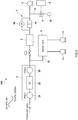
FIG. 1 is a view schematically showing a structure of a particle number counting device according to an embodiment of the present invention. -
FIG. 2 is a view showing relationship data of the same embodiment. -
FIG. 3 is a view schematically showing a structure of a particle number counting device according to a variant embodiment. - Hereinafter, a particle number counting device according to an embodiment of the present invention will be described with reference to the drawings.
- A particle
number counting device 100 of the present embodiment counts particulate matter (i.e., counts a particulate number (PN), hereinafter referred to as a 'particle number') contained in exhaust gas. The exhaust gas is discharged from an exhaust pipe that is connected to an internal combustion engine, and is diluted using a constant volume sampler (CVS) or the like. A portion thereof is then extracted and introduced into the particlenumber counting device 100. Note that it is also possible for the exhaust gas to be diluted using a dilution gas separately from the CVS, or for the exhaust gas to be left undiluted. - More specifically, as is shown in
FIG. 1 , the particlenumber counting device 100 is provided with an exhaustgas processing unit 2 that performs predetermined processing on exhaust gas diluted using a CVS or the like, a particlenumber counting unit 3 that counts a number of particles contained in exhaust gas that has passed through the exhaustgas processing unit 2, a differentialpressure flow meter 4 that is provided downstream from the particlenumber counting unit 3, asuction pump 5 that is provided downstream from the differentialpressure flow meter 4, agas supply path 6 that is connected to a flow path between the differentialpressure flow meter 4 and thesuction pump 5, and supplies gas to a downstream side of the differentialpressure flow meter 4, a flowrate adjustment unit 7 that is provided on thegas supply path 6, and adjusts a flow rate of the gas that is supplied to the downstream side of the differentialpressure flow meter 4, and acontrol unit 8 that controls the flowrate adjustment unit 7. - The exhaust
gas processing unit 2 is a volatile particle remover (VPR) that removes volatile particles that are formed by sulfuric acid mist and a soluble organic fraction (SOF) contained in the exhaust gas. - This
volatile particle remover 2 has aheat diluter 21, anevaporation tube 22, and acold diluter 23. In thevolatile particle remover 2, the exhaust gas is diluted, for example, by a factor of between 10 and 200 by theheat diluter 21 which has a predetermined first heating temperature (for example, 150 ∼ 400 °C), and volatile particles that have already been formed are gasified by theevaporation tube 22 which has a second heating temperature (for example, 300 ∼ 400 °C) provided further downstream. Thereafter, the exhaust gas is once again diluted, for example, by a factor of between 10 and 15 by thecold diluter 23, and the temperature thereof is lowered below a predetermined cooling temperature (for example, 35 °C). As a result, particle generation due to recondensation and particle loss due to thermophoresis are prevented. - The particle
number counting unit 3 is a condensation particle counter (CPC) and operates by causing particulate matter to pass through a supersaturated alcohol (i.e., butanol or the like) atmosphere so that the diameter thereof grows to a large size, and then using laser light to count the particulate matter that is then expelled through a slit. If the introduction flow rate into this condensation particle counter becomes too fast, the growth of the particulate matter becomes insufficient. Because of this, it is desirable that the introduction flow rate be restricted to a predetermined range in which the particulate matter is still able to grow to a desired particle diameter. - The differential
pressure flow meter 4 measures the flow rate of exhaust gas flowing into the particlenumber counting unit 3, and is formed so as to measure the flow rate from a differential pressure between the pressure on an upstream side of anorifice 41 and the pressure on a downstream side thereof. The exhaust gas flow rate obtained by this differentialpressure flow meter 4 is sent to thecontrol unit 8. This differentialpressure flow meter 4 has theorifice 41, which is a diaphragm mechanism that serves as a fluid resistance element, and also has apressure sensor 42 that measures the differential pressure in theorifice 41. - The
suction pump 5 enables exhaust gas that has been processed by the exhaustgas processing unit 2 to flow into the particlenumber counting unit 3, and causes a predetermined differential pressure to be generated in theorifice 41 of the differentialpressure flow meter 4. Thesuction pump 5 of the present embodiment suctions at a constant volume. - The
gas supply path 6 introduces gas between the differentialpressure flow meter 4 and thesuction pump 5. One end thereof is connected to the flow path between the differentialpressure flow meter 4 and thesuction pump 5, while another end thereof is connected to abuffer tank 9. - The
buffer tank 9 is provided on agas discharge path 10 that is connected to the flow path between the exhaustgas processing unit 2 and the particlenumber counting unit 3, and anexhaust pump 11 is also provided on thegas discharge path 10. Thebuffer tank 9 reduces pulsations in theexhaust pump 11. Exhaust gas is introduced into the exhaustgas processing unit 2 via this structure. In addition, because thegas supply path 6 is connected to thebuffer tank 9, exhaust gas is introduced into the exhaustgas processing unit 2 by thesuction pump 5. - Additionally, the flow
rate adjustment unit 7 that is used to adjust the flow rate of the gas that is supplied between the differentialpressure flow meter 4 and thesuction pump 5 is provided on thegas supply path 6. This flowrate adjustment unit 7 is an electromagnetic valve. As a result of the valve opening thereof being controlled by thecontrol unit 8, the flow rate of the gas supplied to the downstream side of the differentialpressure flow meter 4 is adjusted so that the downstream-side pressure in theorifice 41 of the differentialpressure flow meter 4 is also adjusted. - The
control unit 8 controls the valve opening of the flow rate adjustment unit (i.e., the electromagnetic valve) 7 in accordance with the differential pressure between the pressure on the upstream side of theorifice 41 and the pressure on the downstream side thereof as measured by thepressure sensor 42. Here, thecontrol unit 8 controls the flowrate adjustment unit 7 such that the differential pressure between the pressure on the upstream side of theorifice 41 and the pressure on the downstream side thereof falls within a predetermined range. Thecontrol unit 8 controls the flowrate adjustment unit 7 by acquiring a pressure measurement signal from thispressure sensor 42. Here, relationship data showing a relationship between the differential pressure in the fluid resistance element and the valve opening is held in thecontrol unit 8, and a control signal is output to theelectromagnetic valve 7 based on the acquired pressure measurement signal. For example, as is shown inFIG. 2 , the aforementioned relationship data is data showing a relationship between the differential pressure (Pressure drop [kPa]) and the valve opening (Valve opening [%]). As a result of the flowrate adjustment unit 7 being controlled in this way, any variations in the differential pressure in the orifice can be reduced irrespective of changes in the outside air pressure. - According to the particle
number counting device 100 of the present embodiment, because the flowrate adjustment unit 7 is provided on thegas supply path 6 that introduces a gas downstream from the differentialpressure flow meter 4, by adjusting the flow rate of the gas that is supplied to the downstream side of the differential pressure flow meter 4 (i.e., of the orifice 41) in accordance with variations in the outside air pressure, it is possible to reduce variations in the flow rate flowing through theorifice 41. As a result, even if there are variations in the outside air pressure, it is still possible to perform accurate particle number counting. In particular, because thecontrol unit 8 controls theelectromagnetic valve 7, which is serving as the flow rate adjustment unit, it is possible to automatically correct pressure variations, and to thereby improve the measurement accuracy when performing particle number counting. - Moreover, in the present embodiment, because the flow rate of the exhaust gas introduced into the
condensation particle counter 3 is adjusted by thesuction pump 5, and the flow rate of the exhaust gas introduced into the exhaustgas processing unit 2 is principally adjusted by theexhaust pump 11, not only can a satisfactory flow rate be ensured for the exhaust gas flowing into the exhaustgas processing unit 2, but this flow rate can be adjusted to a more appropriate flow rate for enabling particulate matter to be properly grown in thecondensation particle counter 3. - Note that the present invention is not limited to the above-described embodiment.
- For example, the structure shown in
FIG. 3 may also be employed for a particle number counting device. In this particlenumber counting device 100, a structure is employed in which the other end of thegas supply path 6 is open to the atmosphere, and air is introduced via this other end. Ananti-dust filter 12 such as, for example, a HEPA filter or the like is provided on the other end of thegas supply path 6. The flow rate of air that is supplied downstream from the differentialpressure flow meter 4 is adjusted by the flowrate adjustment unit 7 provided on thegas supply path 6. Note that, inFIG. 3 , two exhaust pumps 11 that are used to introduce exhaust gas into the exhaustgas processing unit 2 via thebuffer tank 9 are provided, however, it is also possible to provide only asingle exhaust pump 11. - Other than orifice, it is also possible for a structure that generates a pressure difference between the upstream side and the downstream side to be provided as the fluid resistance element and, for example, a Venturi type or capillary type of fluid resistance element may be used. In addition, a fixed flow meter or a differential pressure gauge or the like that employs these may also be used as the fluid resistance element.
- In addition to the above-described embodiment, it is also possible for a pressure sensor that measures the outside air pressure outside the particle
number counting device 100 to be provided, and for thecontrol unit 8 to control the flowrate adjustment unit 7 using an outside air pressure obtained by this pressure sensor. Here, the pressure sensor that measures the outside air temperature may be the pressure sensor provided in the particlenumber counting device 100, or may be a pressure sensor that is provided independently of the particlenumber counting device 100. Furthermore, it is also possible to employ a structure in which a pressure sensor that measures the pressure on the upstream side of the fluid resistance element to be provided, and for thecontrol unit 8 to control the flowrate adjustment unit 7 using an upstream-side pressure obtained by this pressure sensor. - In the above-described embodiment, a structure is employed in which a buffer tank is provided in order to reduce pulsation, however, it is not essential that the buffer tank be provided.
- In addition, in the above-described embodiment, a structure is employed in which the
gas discharge path 10 and theexhaust pump 11 are provided, however, it is not essential that these be provided. In this case, thesuction pump 5 is used to not only introduce exhaust gas into the exhaustgas processing unit 2, but to also introduce diluted exhaust gas into the particlenumber counting unit 3. - Furthermore, it should be understood that the present invention is not limited to the above-described embodiment, and that various modifications and the like may be made thereto insofar as they do not depart from the spirit or scope of the present invention.
-
- 100
- Particle Number Counting Device
- 2
- Exhaust Gas Processing Unit
- 3
- Particle Number Counting Unit
- 4
- Differential Pressure Flow Meter
- 41
- Orifice (Fluid Resistance Element)
- 42
- Pressure Sensor
- 5
- Suction Pump
- 6
- Gas Supply Path
- 7
- Flow Rate Adjustment Unit
- 8
- Control Unit
- 9
- Buffer Tank
- 10
- Gas Discharge Path
- 11
- Exhaust Pump
Claims (6)
- A particle number counting device comprising:a particle number counting unit that counts a number of particles contained in exhaust gas;a fluid resistance element that is provided downstream from the particle number counting unit;a suction pump that is provided downstream from the fluid resistance element;a gas supply path that is connected to a flow path between the fluid resistance element and the suction pump, and that supplies gas to a downstream side of the fluid resistance element; anda flow rate adjustment unit that is provided on the gas supply path, and that adjusts a flow rate of the gas that is supplied to the downstream side of the fluid resistance element.
- The particle number counting device according to Claim 1, further comprising a pressure sensor that measures a differential pressure between a pressure on the upstream side of the fluid resistance element and a pressure on the downstream side thereof, or a pressure on the upstream side of the fluid resistance element, or an outside air pressure, and
the flow rate adjustment unit adjusts the flow rate based on pressure measurements made by the pressure sensor. - The particle number counting device according to Claim 2, wherein the flow rate adjustment unit adjusts the flow rate such that a differential pressure between a pressure on the upstream side of the fluid resistance element and a pressure on the downstream side thereof is within a predetermined range
- The particle number counting device according to any one of Claims 1 to 3, wherein the gas supply path is connected to the flow path between an exhaust gas processing unit and the particle number counting unit via a buffer tank.
- The particle number counting device according to any one of Claims 1 to 3, further comprising:an exhaust gas processing unit that is provided upstream from the particle number counting unit, and that performs predetermined processing on exhaust gas;a gas discharge path that is connected to the flow path between the exhaust gas processing unit and the particle number counting unit;an exhaust pump that is provided on the gas discharge path; anda buffer tank that is provided on the gas discharge path on the upstream side of the exhaust pump, whereinthe gas supply path is connected to the buffer tank.
- A particle number counting method that employs a particle number counting device comprising a particle number counting unit that counts a number of particles contained in exhaust gas, a fluid resistance element that is provided downstream from the particle number counting unit, a suction pump that is provided downstream from the fluid resistance element, a gas supply path that is connected to a flow path between the fluid resistance element and the suction pump, and that supplies gas to a downstream side of the fluid resistance element, and a flow rate adjustment unit that is provided on the gas supply path, and that adjusts a flow rate of the gas that is supplied to the downstream side of the fluid resistance element, wherein
the flow rate adjustment unit is controlled based on a differential pressure between a pressure on the upstream side of the fluid resistance element and a pressure on the downstream side thereof, or on a pressure on the upstream side of the fluid resistance element, or on an outside air pressure.
Applications Claiming Priority (1)
| Application Number | Priority Date | Filing Date | Title |
|---|---|---|---|
| JP2018230563A JP7217624B2 (en) | 2018-12-10 | 2018-12-10 | Particle number measuring device and particle number measuring method |
Publications (2)
| Publication Number | Publication Date |
|---|---|
| EP3667289A2 true EP3667289A2 (en) | 2020-06-17 |
| EP3667289A3 EP3667289A3 (en) | 2020-07-29 |
Family
ID=67809240
Family Applications (1)
| Application Number | Title | Priority Date | Filing Date |
|---|---|---|---|
| EP19194212.7A Withdrawn EP3667289A3 (en) | 2018-12-10 | 2019-08-28 | Particle number counting device and particle number counting method |
Country Status (3)
| Country | Link |
|---|---|
| US (1) | US11187641B2 (en) |
| EP (1) | EP3667289A3 (en) |
| JP (1) | JP7217624B2 (en) |
Families Citing this family (1)
| Publication number | Priority date | Publication date | Assignee | Title |
|---|---|---|---|---|
| FI129009B (en) * | 2020-02-05 | 2021-05-14 | Dekati Oy | Method and apparatus for monitoring number density of aerosol particles |
Citations (1)
| Publication number | Priority date | Publication date | Assignee | Title |
|---|---|---|---|---|
| JP2012127773A (en) | 2010-12-15 | 2012-07-05 | Shimadzu Corp | Particulate number measuring device |
Family Cites Families (7)
| Publication number | Priority date | Publication date | Assignee | Title |
|---|---|---|---|---|
| GB1454602A (en) * | 1974-05-02 | 1976-11-03 | Jenkins A | Apparatus for checking the contents of closed containers |
| US6502450B1 (en) * | 1999-05-10 | 2003-01-07 | Rupprecht & Patashnik Company, Inc. | Single detector differential particulate mass monitor with intrinsic correction for volatilization losses |
| KR100614101B1 (en) | 2005-09-15 | 2006-08-22 | 한국과학기술연구원 | Particle counter |
| JP5630894B2 (en) * | 2010-02-05 | 2014-11-26 | 株式会社堀場製作所 | Particulate matter measuring device |
| JP2012154657A (en) | 2011-01-24 | 2012-08-16 | Shimadzu Corp | Aerosol fine particle measurement device |
| WO2013109942A1 (en) | 2012-01-20 | 2013-07-25 | Tsi, Incorporated | Instrument for sizing nanoparticles and a component therefor |
| US9708960B2 (en) * | 2013-05-08 | 2017-07-18 | Cummins Ip, Inc. | Exhaust aftertreatment system diagnostic and conditioning |
-
2018
- 2018-12-10 JP JP2018230563A patent/JP7217624B2/en active Active
-
2019
- 2019-08-28 EP EP19194212.7A patent/EP3667289A3/en not_active Withdrawn
- 2019-09-09 US US16/564,931 patent/US11187641B2/en not_active Expired - Fee Related
Patent Citations (1)
| Publication number | Priority date | Publication date | Assignee | Title |
|---|---|---|---|---|
| JP2012127773A (en) | 2010-12-15 | 2012-07-05 | Shimadzu Corp | Particulate number measuring device |
Also Published As
| Publication number | Publication date |
|---|---|
| US20200182767A1 (en) | 2020-06-11 |
| JP2020094810A (en) | 2020-06-18 |
| JP7217624B2 (en) | 2023-02-03 |
| EP3667289A3 (en) | 2020-07-29 |
| US11187641B2 (en) | 2021-11-30 |
Similar Documents
| Publication | Publication Date | Title |
|---|---|---|
| CN101680821B (en) | Exhaust gas sampling diluter and method | |
| KR101767271B1 (en) | Exhaust gas analyzing system | |
| US8789406B2 (en) | Exhaust gas sampling and analysis system | |
| EP2102623B1 (en) | Solid particle counting system with valve to allow reduction of pressure pulse at particle counter when vacuum pump is started | |
| CN210862863U (en) | Gas flowmeter calibrating device | |
| CN104364630A (en) | Exhaust gas dilution device | |
| CN101571471A (en) | Method for detecting cigarette smoke aerosol particle size distribution | |
| JP6918927B2 (en) | Passive aerosol diluter mechanism | |
| US11187641B2 (en) | Particle number counting device and particle number counting method | |
| CN104122122B (en) | Pressure stability sampling apparatus | |
| JP5476193B2 (en) | Particle counting system | |
| CN204064740U (en) | Pressure stability sampling apparatus | |
| EP3803333B1 (en) | Condensation particle counter efficiency compensation for altitude | |
| EP2354779B1 (en) | Particulate matter measurement device | |
| KR100726207B1 (en) | Wall Inlet Compact Mini Tunnel Dilutor | |
| JP2007024730A (en) | Apparatus and method for sampling diluted exhaust gas using laminar exhaust gas flowmeter and heating/cooling surge tube apparatus | |
| CN208000232U (en) | System for detecting leaks in an exhaust gas sampling device | |
| CN201434815Y (en) | Real-time detection device for cigarette smoke aerosol particle size distribution | |
| CN116072506A (en) | Particle sampling device, aerosol mass spectrometer, single particle diameter measurement method | |
| US11656236B2 (en) | Mirror calibration of multiple flow-measurement devices | |
| JP3628126B2 (en) | Extraction device and dilution device | |
| US20110266430A1 (en) | Gas inlet for a process mass spectrometer | |
| JPH0640053B2 (en) | Device for measuring particulate matter in exhaust gas |
Legal Events
| Date | Code | Title | Description |
|---|---|---|---|
| PUAI | Public reference made under article 153(3) epc to a published international application that has entered the european phase |
Free format text: ORIGINAL CODE: 0009012 |
|
| STAA | Information on the status of an ep patent application or granted ep patent |
Free format text: STATUS: THE APPLICATION HAS BEEN PUBLISHED |
|
| AK | Designated contracting states |
Kind code of ref document: A2 Designated state(s): AL AT BE BG CH CY CZ DE DK EE ES FI FR GB GR HR HU IE IS IT LI LT LU LV MC MK MT NL NO PL PT RO RS SE SI SK SM TR |
|
| AX | Request for extension of the european patent |
Extension state: BA ME |
|
| PUAL | Search report despatched |
Free format text: ORIGINAL CODE: 0009013 |
|
| AK | Designated contracting states |
Kind code of ref document: A3 Designated state(s): AL AT BE BG CH CY CZ DE DK EE ES FI FR GB GR HR HU IE IS IT LI LT LU LV MC MK MT NL NO PL PT RO RS SE SI SK SM TR |
|
| AX | Request for extension of the european patent |
Extension state: BA ME |
|
| RIC1 | Information provided on ipc code assigned before grant |
Ipc: G01N 15/06 20060101AFI20200622BHEP |
|
| STAA | Information on the status of an ep patent application or granted ep patent |
Free format text: STATUS: REQUEST FOR EXAMINATION WAS MADE |
|
| 17P | Request for examination filed |
Effective date: 20210126 |
|
| RBV | Designated contracting states (corrected) |
Designated state(s): AL AT BE BG CH CY CZ DE DK EE ES FI FR GB GR HR HU IE IS IT LI LT LU LV MC MK MT NL NO PL PT RO RS SE SI SK SM TR |
|
| STAA | Information on the status of an ep patent application or granted ep patent |
Free format text: STATUS: EXAMINATION IS IN PROGRESS |
|
| 17Q | First examination report despatched |
Effective date: 20220124 |
|
| STAA | Information on the status of an ep patent application or granted ep patent |
Free format text: STATUS: THE APPLICATION IS DEEMED TO BE WITHDRAWN |
|
| 18D | Application deemed to be withdrawn |
Effective date: 20230503 |