EP3667227A1 - Vorrichtung zum entschliessen einer explosivladung und munition mit einer solchen vorrichtung - Google Patents
Vorrichtung zum entschliessen einer explosivladung und munition mit einer solchen vorrichtung Download PDFInfo
- Publication number
- EP3667227A1 EP3667227A1 EP19213460.9A EP19213460A EP3667227A1 EP 3667227 A1 EP3667227 A1 EP 3667227A1 EP 19213460 A EP19213460 A EP 19213460A EP 3667227 A1 EP3667227 A1 EP 3667227A1
- Authority
- EP
- European Patent Office
- Prior art keywords
- projectile
- deconfinement
- explosive charge
- opening
- deconfinement device
- Prior art date
- Legal status (The legal status is an assumption and is not a legal conclusion. Google has not performed a legal analysis and makes no representation as to the accuracy of the status listed.)
- Pending
Links
- 239000002360 explosive Substances 0.000 title claims abstract description 90
- 230000001960 triggered effect Effects 0.000 claims abstract description 28
- 238000007789 sealing Methods 0.000 claims abstract description 16
- 239000007788 liquid Substances 0.000 claims abstract description 8
- 230000000694 effects Effects 0.000 claims description 12
- 230000006835 compression Effects 0.000 claims description 5
- 238000007906 compression Methods 0.000 claims description 5
- 239000012781 shape memory material Substances 0.000 claims description 3
- 230000002040 relaxant effect Effects 0.000 claims description 2
- 238000002485 combustion reaction Methods 0.000 description 14
- 208000031968 Cadaver Diseases 0.000 description 12
- 230000037452 priming Effects 0.000 description 12
- 238000006243 chemical reaction Methods 0.000 description 11
- 238000005474 detonation Methods 0.000 description 8
- 230000008859 change Effects 0.000 description 7
- 238000004200 deflagration Methods 0.000 description 7
- 238000004880 explosion Methods 0.000 description 7
- 230000000977 initiatory effect Effects 0.000 description 7
- 230000016571 aggressive behavior Effects 0.000 description 6
- 230000015556 catabolic process Effects 0.000 description 6
- 238000006731 degradation reaction Methods 0.000 description 6
- 238000010438 heat treatment Methods 0.000 description 6
- 239000007789 gas Substances 0.000 description 5
- 230000004044 response Effects 0.000 description 5
- 238000000926 separation method Methods 0.000 description 5
- 230000006870 function Effects 0.000 description 4
- 230000002238 attenuated effect Effects 0.000 description 3
- 230000008901 benefit Effects 0.000 description 3
- 230000009172 bursting Effects 0.000 description 3
- 239000000567 combustion gas Substances 0.000 description 3
- 230000004927 fusion Effects 0.000 description 3
- 230000003313 weakening effect Effects 0.000 description 3
- 239000000463 material Substances 0.000 description 2
- 238000000034 method Methods 0.000 description 2
- 239000003380 propellant Substances 0.000 description 2
- 230000035945 sensitivity Effects 0.000 description 2
- 230000007704 transition Effects 0.000 description 2
- 206010001488 Aggression Diseases 0.000 description 1
- 208000031872 Body Remains Diseases 0.000 description 1
- 108091030087 Initiator element Proteins 0.000 description 1
- 241000897276 Termes Species 0.000 description 1
- 238000000354 decomposition reaction Methods 0.000 description 1
- 238000009499 grossing Methods 0.000 description 1
- 238000004519 manufacturing process Methods 0.000 description 1
- 238000002844 melting Methods 0.000 description 1
- 230000008018 melting Effects 0.000 description 1
- 230000035939 shock Effects 0.000 description 1
- 239000007787 solid Substances 0.000 description 1
- 238000003860 storage Methods 0.000 description 1
- 238000003466 welding Methods 0.000 description 1
Images

Classifications
-
- F—MECHANICAL ENGINEERING; LIGHTING; HEATING; WEAPONS; BLASTING
- F42—AMMUNITION; BLASTING
- F42B—EXPLOSIVE CHARGES, e.g. FOR BLASTING, FIREWORKS, AMMUNITION
- F42B12/00—Projectiles, missiles or mines characterised by the warhead, the intended effect, or the material
- F42B12/02—Projectiles, missiles or mines characterised by the warhead, the intended effect, or the material characterised by the warhead or the intended effect
- F42B12/20—Projectiles, missiles or mines characterised by the warhead, the intended effect, or the material characterised by the warhead or the intended effect of high-explosive type
- F42B12/207—Projectiles, missiles or mines characterised by the warhead, the intended effect, or the material characterised by the warhead or the intended effect of high-explosive type characterised by the explosive material or the construction of the high explosive warhead, e.g. insensitive ammunition
-
- F—MECHANICAL ENGINEERING; LIGHTING; HEATING; WEAPONS; BLASTING
- F42—AMMUNITION; BLASTING
- F42B—EXPLOSIVE CHARGES, e.g. FOR BLASTING, FIREWORKS, AMMUNITION
- F42B39/00—Packaging or storage of ammunition or explosive charges; Safety features thereof; Cartridge belts or bags
- F42B39/20—Packages or ammunition having valves for pressure-equalising; Packages or ammunition having plugs for pressure release, e.g. meltable ; Blow-out panels; Venting arrangements
Definitions
- the present invention relates to a device for deconfining an explosive charge.
- a reference system making it possible to classify the various armaments according to their level of security.
- Such a reference system may in particular define a certain number of tests to which armaments will be subjected and their admissible reaction levels in an accidental environment. These tests are representative of the attacks that armaments can undergo during their operational life.
- STANAG corresponds to the abbreviation of the English term "Standardization Agreement", which in French is called “Standardization Agreements” includes documents which define the procedures, terms and conditions adopted by NATO member countries concerning military systems and equipment.
- Attenuated risk munitions are munitions which, subjected to thermal aggression, must not react violently, and must therefore react in a controlled manner.
- the technical problem is therefore to provide ammunition offering a type V (combustion of the ammunition) or VI (no reaction) response to a thermal attack of the slow or rapid heating type.
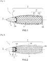
- Ammunition as shown in the figure 1 , generally comprises a propellant element (not shown in the figures) connected to a projectile element 1.
- the projectile element 1 is an elongated element in the longitudinal direction X.
- the projectile element 1, also by simplification "projectile”, comprises a first part 2 containing the explosive charge 21 and a second part 3 comprising an explosive charge trigger / initiator element, typically comprising a priming chain.
- the explosive charge is contained in a body 22, also called an "ammunition body".
- the body may have a thickness of between a few millimeters to a few centimeters.
- the body can also be in at least two parts 221, 222. It can also have an open end 22a located opposite the second part, its opposite end 22b being closed.
- the first part can be called “loaded body”.
- the second part can be called “rocket”.
- a priming relay can be arranged, completing the priming chain.
- Devices exist to secure the ammunition. Their principle is generally to deconfigure the explosive charge. They exploit one or more of the different phenomena that can take place when heat is transmitted to a munition. Indeed, when an ammunition does not have a security system and is subjected to a thermal attack, it sees its explosive charge rise in temperature which can reach the degradation temperature of said explosive charge first causing combustion thereof. Then, under the effect of the confinement of the explosive charge in the body, the ammunition is capable of passing through a pneumatic explosion, even a deflagration or a detonation. This is why it is necessary to quickly open the body of the explosive charge once the ammunition is subjected to aggression, so that the explosive is deconfinite and can, in the worst case, burn in the open air.
- the opening of the body can be achieved by a separation of the first and second parts.
- the first phenomenon exploited is the degradation of the explosive, and therefore its combustion, generating a combustion gas and consequently an overpressure in the projectile.
- This overpressure must allow controlled opening or even bursting of the body.
- the second phenomenon exploited is the change of phase (the fusion) of all or part of the explosive charge, causing a change in density, and consequently a hydraulic overpressure in the body and therefore in the projectile.
- This overpressure must allow controlled opening or even bursting of the body.
- the opening in the projectile must intervene quickly, at least sufficiently before a pyrotechnic phenomenon (combustion, deflagration, detonation) occurs.
- This second phenomenon is notably exploited in the patent application FR2922638 describing a munition which comprises an energy charge confined in an envelope, the energy charge being able to expand during a phase change at a temperature below its decomposition temperature, and the envelope comprising at least two parts connected by a mechanical connection adapted to break under the effect of the internal pressure of the envelope caused during a change of phase of the load.
- a so-called deconfinement device which uses a zone of physical weakening of the projectile, which is either an area of the body, or an interface piece (for example between the first and second parts or between two parts of the body) and which plays the role of mechanical fuse, in order to precisely control the opening of the body and deconfigure the explosive charge.
- a pyrotechnic event is necessary to open the body.
- the risk of runaway and transition from combustion to an explosion and / or a deflagration and / or a detonation is high if the opening of the body is not fast enough and / or if it does not reach a size sufficient to sufficiently deconfigure the explosive charge.
- the device only works if the body remains tight to the liquid (respectively to the gas). However, once the body begins to open, or in the event of a leak, the fusion liquid (respectively the combustion gas) escapes, canceling any pressure effort and thereby limiting the capacities of opening of the deconfinement device.
- the temperature may continue to increase, or even reach the degradation temperature of the explosive charge.
- the trigger for the explosive charge is likely to maintain its proximity to said explosive charge.
- this trigger element rises in temperature, until the pyrotechnic elements it contains reacts, the induced effects can cause the uncontrolled initiation of the explosive charge by the proximity of the two parts.
- the invention aims to overcome the aforementioned drawbacks of the prior art.
- it aims to have a device for deconfining the explosive charge for an ammunition projectile making it possible to guarantee better securing of the ammunition, and in particular to ensure that the ammunition has a type V response (combustion of the ammunition) or type VI (no reaction) to a thermal attack of the slow or rapid heating type.
- the invention aims to have a deconfinement device which makes it possible to avoid maintaining a proximity between the triggering element and the explosive charge.
- explosive charge should be understood as “main explosive charge”.
- the first object of the invention is a deconfinement device for a projectile using the pressure generated by a phase change of the explosive charge (liquid or gaseous) to trigger an opening in the projectile, for example but not exclusively an opening between the charge explosive and rocket.
- the deconfinement device of the invention comprises an opening means or system of the mechanical fuse type capable of opening under the effect of pressure, and a sealing means, typically a seal, configured so as to ensure that the pressure in the projectile and / or in the body can reach a threshold pressure for triggering the fuse-type system.
- the deconfinement device ensures by a thrust means, such as a spring, that the opening in the projectile is rapid and of sufficient size to guarantee deconfinement.
- the pushing means operates in combination with the opening means so that it is triggered only when the opening means is itself triggered, and therefore when the opening has been initiated.
- the invention thus makes it possible to improve the known deconfinement systems.
- the deconfinement device is configured so as to allow an opening between the first part (comprising the explosive charge) and the second part (the priming rocket) of the projectile.
- the opening means is disposed between the first part and the second part of the projectile.
- the body comprises a first part and a second part
- the deconfinement device is configured so as to allow an opening between said first part and said second part of the body.
- the opening means is disposed between the first part and the second part of the body.
- the objective of the invention is to guarantee better security of the ammunition, and in particular to ensure that the munition presents in the worst case a type V response (combustion of the ammunition) to a thermal attack of the slow or rapid heating type.
- a type V response combustion of the ammunition
- the projectile is deconfined, it may be that a small amount of explosive charge is still close to the rocket, the main thing being that the major part of said charge is removed from it when the deconfinement device is triggered.
- the deconfinement device and more broadly the projectile will be dimensioned to make it possible to ensure that at least a major part of the explosive charge is no longer in the immediate vicinity of the rocket.
- the first phenomenon exploited is the degradation of the explosive and therefore its combustion, generating a combustion gas and consequently an overpressure in the projectile, and when the opening means is disposed at the level of the body, it is ensured that the opening triggered by the overpressure and increased tenfold by the pushing means allows sufficient distance between the ignition chain and at least a major part of the explosive charge.
- the explosive charge is in the form of a divided solid, it can escape through the opening formed in the projectile.
- the molten liquid explosive may escape through the opening formed in the projectile. This ensures that a major part of the explosive is distant from the rest of the projectile and therefore in particular from the rocket.
- the opening means comprises a mechanical part capable of breaking when the internal pressure is greater than or equal to the given pressure threshold, for example a threaded part whose thread is capable of smoothing when the internal pressure is greater than or equal to the given pressure threshold.
- the pushing means comprises a compression spring capable of relaxing once the opening means have been triggered.
- the pushing means comprises a blade capable of releasing a pushing force once the opening means have been triggered.
- the pushing means comprises a shape memory material capable of expanding under the effect of temperature.
- the sealing means comprises at least one seal.
- the deconfinement device further comprises a first part connected to the first part of the projectile and disposed between said first and the second part of the projectile, the sealing means and the thrust means being disposed between said first part and said second part of the projectile.
- Said first part can serve as a bearing surface for the pushing means, and can also serve to protect the explosive charge when a pushing force is exerted.
- the deconfinement device further comprises a second part, connected to the second part of the projectile and disposed between the first part and said second part of the projectile, the sealing means and the thrust means being disposed between said second part and said first part of the projectile, or between said second part and said first part.
- the sealing means is disposed on the first part or on the second part.
- the pushing means is connected to the first part or to the second part.
- the opening means is connected to the first part or to the second part.
- a second object of the invention is a munition comprising a projectile provided with the deconfinement device according to the first object of the invention.
- the figures 2 , 3 and 4 represent a first example of deconfinement device 4 according to the invention, seen in closed configuration (device not triggered) and in open configuration (device triggered). They use the same reference numbers as the figure 1 for common elements with the figure 1 .
- the figures 2 , 3 and 4 illustrate a projectile element 1 for ammunition.
- the propellant of the ammunition is not shown in the figures.
- the projectile element 1 is an elongated element in the longitudinal direction X and has a symmetry with respect to said longitudinal direction.
- the projectile element 1 comprises a first part 2 containing the explosive charge 21 and a second part 3 comprising an element triggering the explosive charge.
- first and second parts are shown as integral (so-called “closed” configuration).
- first and second parts are shown separated (configuration called "open").
- the first part 2 comprises an ammunition body 22, also called a “body”, delimiting an internal cavity containing the explosive charge 21.
- the body 22 is in a single part.
- the body may have a thickness of between a few millimeters to a few centimeters.
- the body 22 has an open end 22a located opposite the second part 3, its opposite end 22b being closed.
- the second part comprises a priming relay 31 disposed between the second part and the first part.
- the first part can be called for simplicity "loaded body”.
- the second part can be called “priming rocket” or for simplicity “rocket”.
- the rocket is shown here schematically.
- the rocket may comprise, in addition to a priming chain, electronic or mechanical means making it possible to operate, a safety device, means for initiating the priming chain.
- the rocket closes the ammunition body 22 by closing off its open end 22a, thus ensuring the confinement of the explosive charge 21.
- the deconfinement system 4 is disposed between the rocket 3 and the loaded body 2. Said deconfinement system makes it possible to form a connection between said rocket and said loaded body (system not triggered), or to break said connection (system triggered). When the link is broken, that is to say when the deconfinement system is triggered, the rocket and the loaded body are disconnected.
- the bearing surface of the pushing means 45 may be directly formed by an internal surface of the open end 22a of the ammunition body 22, without the need for a first cup.
- the confinement ring is positioned on the second cup.
- it can be positioned on the first cup.
- the confinement ring can be positioned directly at the end 3a of the rocket which is opposite the loaded body 2, without it being necessary to have a first cup and / or a second cup.
- the pushing means can be a blade or a piece of shape memory material capable of expanding under the effect of temperature, and in general any means capable of achieving an effort of rapid push between two bodies.
- one of the first and the second cup can be with shape memory and thus fulfill the rapid pushing function in place of a spring.
- the opening means can be a part, such as a pin, capable of being sheared at the defined pressure, or a bonding or welding dimensioned to resist up to the defined pressure, or alternatively a part of which a weakened part is dimensioned to resist up to the defined pressure.
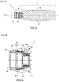
- the Figures 5 and 6 illustrate a second embodiment of a deconfinement device 4 'for a projectile 1'.
- the figure 5 represents the projectile 1 'in closed configuration (device not triggered).
- the figure 6 represents the projectile 1 'in open configuration (device triggered).
- the second example differs from the first example in that the opening is generated on the body which separates into two parts and in that the opening means 43 ', or ring of deconfinement, is not disposed between the rocket and the loaded body, but that it is placed at the level of the body 22 ', the body comprising a first part 221' arranged opposite the rocket 3 'and a second part 222' arranged in the opposite direction from said rocket.
- the opening means 43 ' or ring of deconfinement
- the body 22 ' When the deconfinement device is triggered ( figure 6 ), the body 22 'is open between the first and second parts 221' and 222 'thanks to the opening means 43' and almost instantly the spring 45 'disposed between the rocket 3' and the loaded body 2 'acts by pushing the second part 222 'carrying with it the explosive charge 21'. This ensures a sufficient separation distance between said explosive charge and the rocket 3 '.
- the pushing means 45 ' is, as in the first embodiment, disposed between the rocket and the loaded body.
- the pushing means can be disposed between the first or second parts of the body, or at any other place in the projectile adapted to ensure the same function of distance.
- the sealing means 44 ' is arranged between the rocket and the loaded body.
- sealing means can be arranged between the first and second parts of the body (not shown in the figures).
- the invention makes it possible to obtain rapid deconfinement and of significant amplitude, which makes it possible to limit the overpressure phase of the explosive charge over time.
- the thrust system takes over and significantly enlarges the opening of the projectile independently of the state of the explosive charge. In other words, it is no longer necessary that a pressure (gas pressure in the event of combustion or hydraulic pressure in the event of the explosive melting) is maintained.
- the opening of the projectile is controlled by overpressure and not by temperature, which guarantees the integrity of the mechanical elements.
- the pressure control according to the invention also allows the maximum temperature reached by the projectile is significantly lower than the degradation temperature of the explosive charge.
- the distance between the rocket and the explosive charge (or most of the explosive charge) allows the explosive charge to be moved away from the initiation system.
- the deconfinement device can be configured so that the rocket or the explosive charge is completely ejected from the projectile. Whether allowing the rocket or the explosive charge to be ejected, this makes it possible in particular to prevent an untimely initiation of the explosive charge following an unwanted initiation of the priming chain.
- the opening of the projectile made possible by the invention makes it possible to ensure a sufficient rate of gas leakage, in particular linked to degradation phenomena, to avoid runaway from the combustion of the explosive and the deflagration of said explosive.
- the invention guarantees a type V or VI response to thermal attack.
Landscapes
- Engineering & Computer Science (AREA)
- General Engineering & Computer Science (AREA)
- Chemical & Material Sciences (AREA)
- Combustion & Propulsion (AREA)
- Portable Nailing Machines And Staplers (AREA)
Applications Claiming Priority (1)
| Application Number | Priority Date | Filing Date | Title |
|---|---|---|---|
| FR1872833A FR3090086B1 (fr) | 2018-12-13 | 2018-12-13 | Dispositif de deconfinement d’un chargement explosif et munition equipee d’un tel dispositif |
Publications (1)
| Publication Number | Publication Date |
|---|---|
| EP3667227A1 true EP3667227A1 (de) | 2020-06-17 |
Family
ID=66690500
Family Applications (1)
| Application Number | Title | Priority Date | Filing Date |
|---|---|---|---|
| EP19213460.9A Pending EP3667227A1 (de) | 2018-12-13 | 2019-12-04 | Vorrichtung zum entschliessen einer explosivladung und munition mit einer solchen vorrichtung |
Country Status (6)
| Country | Link |
|---|---|
| US (1) | US11054229B2 (de) |
| EP (1) | EP3667227A1 (de) |
| JP (1) | JP7344771B2 (de) |
| AU (1) | AU2019279915A1 (de) |
| CA (1) | CA3064910A1 (de) |
| FR (1) | FR3090086B1 (de) |
Citations (7)
| Publication number | Priority date | Publication date | Assignee | Title |
|---|---|---|---|---|
| US5035181A (en) * | 1985-01-22 | 1991-07-30 | The United States Of America As Represented By The Secretary Of The Navy | Thermosensitive pop-out device |
| FR2906606A1 (fr) * | 2006-09-29 | 2008-04-04 | Giat Ind Sa | Dispositif de deconfinement d'une enveloppe d'une munition. |
| FR2922638A1 (fr) | 2007-10-23 | 2009-04-24 | Tda Armements Sas Soc Par Acti | Chargement energetique a deconfinement controle et munition equipee d'un tel chargement |
| EP2275774A1 (de) * | 2009-07-17 | 2011-01-19 | Tda Armements S.A.S. | Munition mit Mitteln zur Neutralisierung seiner Sprengladung |
| EP2461129A1 (de) * | 2010-12-03 | 2012-06-06 | Tda Armements S.A.S. | Vorrichtung zum Verhärten einer mechanischen Verbindung eines Antriebs für Kanonenmunition, und mit einer solchen Verbindung ausgestattete Munition |
| FR2995075A1 (fr) | 2012-08-29 | 2014-03-07 | Nexter Munitions | Fusee d'amorcage permettant le deconfinement d'une enveloppe de munition |
| EP2933598A2 (de) * | 2014-04-18 | 2015-10-21 | Nostromo, LLC | In einer munition angebrachter separator mit mehreren aktionen zum trennen des zünders vom gefechtskopf |
Family Cites Families (6)
| Publication number | Priority date | Publication date | Assignee | Title |
|---|---|---|---|---|
| CH584394A5 (de) * | 1974-04-26 | 1977-01-31 | Sarmac Sa | |
| US6035631A (en) * | 1995-07-04 | 2000-03-14 | Royal Ordnance Public Limited Company | Safety in solid fuel rocket motors |
| US8082846B2 (en) * | 2002-08-12 | 2011-12-27 | Qinetiq Limited | Temperature responsive safety devices for munitions |
| US9366282B2 (en) | 2013-09-06 | 2016-06-14 | Thomas & Betts International Llc | Torque controlling break screw |
| KR101700037B1 (ko) * | 2015-07-15 | 2017-01-26 | (주)수아 | 화약 작동에 의해 개구부가 형성되는 고폭탄용 운반고리 |
| US10378870B1 (en) * | 2018-05-30 | 2019-08-13 | The United States Of America As Represented By The Secretary Of The Army | Energy absorbing flange for meltable fuze plug |
-
2018
- 2018-12-13 FR FR1872833A patent/FR3090086B1/fr active Active
-
2019
- 2019-11-25 JP JP2019212242A patent/JP7344771B2/ja active Active
- 2019-12-04 EP EP19213460.9A patent/EP3667227A1/de active Pending
- 2019-12-04 US US16/703,787 patent/US11054229B2/en active Active
- 2019-12-09 AU AU2019279915A patent/AU2019279915A1/en active Pending
- 2019-12-12 CA CA3064910A patent/CA3064910A1/en active Pending
Patent Citations (7)
| Publication number | Priority date | Publication date | Assignee | Title |
|---|---|---|---|---|
| US5035181A (en) * | 1985-01-22 | 1991-07-30 | The United States Of America As Represented By The Secretary Of The Navy | Thermosensitive pop-out device |
| FR2906606A1 (fr) * | 2006-09-29 | 2008-04-04 | Giat Ind Sa | Dispositif de deconfinement d'une enveloppe d'une munition. |
| FR2922638A1 (fr) | 2007-10-23 | 2009-04-24 | Tda Armements Sas Soc Par Acti | Chargement energetique a deconfinement controle et munition equipee d'un tel chargement |
| EP2275774A1 (de) * | 2009-07-17 | 2011-01-19 | Tda Armements S.A.S. | Munition mit Mitteln zur Neutralisierung seiner Sprengladung |
| EP2461129A1 (de) * | 2010-12-03 | 2012-06-06 | Tda Armements S.A.S. | Vorrichtung zum Verhärten einer mechanischen Verbindung eines Antriebs für Kanonenmunition, und mit einer solchen Verbindung ausgestattete Munition |
| FR2995075A1 (fr) | 2012-08-29 | 2014-03-07 | Nexter Munitions | Fusee d'amorcage permettant le deconfinement d'une enveloppe de munition |
| EP2933598A2 (de) * | 2014-04-18 | 2015-10-21 | Nostromo, LLC | In einer munition angebrachter separator mit mehreren aktionen zum trennen des zünders vom gefechtskopf |
Also Published As
| Publication number | Publication date |
|---|---|
| CA3064910A1 (en) | 2020-06-13 |
| FR3090086A1 (fr) | 2020-06-19 |
| FR3090086B1 (fr) | 2020-12-11 |
| US20200191538A1 (en) | 2020-06-18 |
| US11054229B2 (en) | 2021-07-06 |
| JP2020094795A (ja) | 2020-06-18 |
| AU2019279915A1 (en) | 2020-07-02 |
| JP7344771B2 (ja) | 2023-09-14 |
Similar Documents
| Publication | Publication Date | Title |
|---|---|---|
| EP2079980B1 (de) | Vorrichtung zum entschliessen einer munitionshülse | |
| US8997774B2 (en) | Pressure discharge valve | |
| EP1548393B1 (de) | Vorrichtung zur Entschliessung einer Munitionshülle | |
| EP0545764B1 (de) | Verriegelungsvorrichtung einer Hülse die pyrotechnische Materialien enthält | |
| FR2948186A1 (fr) | Munition comprenant des moyens pour neutraliser son chargement explosif | |
| EP0554149A1 (de) | Zünderkopf | |
| EP3667227A1 (de) | Vorrichtung zum entschliessen einer explosivladung und munition mit einer solchen vorrichtung | |
| WO2005098346A1 (fr) | Dispositif emetteur de rayonnement notamment infrarouge | |
| FR2627272A1 (fr) | Enveloppe metallique d'une munition destinee a contenir une charge explosive confinee et procede pour sa fabrication | |
| US20060032562A1 (en) | Method for reducing violence of accidental explosions in solid fuel rocket motors and other energetic devices | |
| FR2811053A1 (fr) | Dispositif de minimisation des effets deflagrants d'une enceinte metallique en cas de surpression interne accidentelle | |
| EP2703769B1 (de) | Vorrichtung zum Entschliessen einer Munitionshülse | |
| EP2053344B1 (de) | Energetische Ladung mit kontrollierter Entsicherung und Munition, die mit einer solchen Ladung ausgerüstet ist | |
| EP0211703B1 (de) | Verschlussstopfen für eine Feststofftreibladung mit zwei Kammern | |
| EP2029956B1 (de) | Sicherheitszünder für pyrotechnische vorrichtung | |
| EP2769168B1 (de) | Gasgenerator mit einer sicherheitsvorrichtung für langsame erhitzung | |
| FR2633385A1 (fr) | Systeme de securite et d'armement pour projectile utilisant la pression des gaz de combustion | |
| EP0045226B1 (de) | Mittels Reibung oder heisser Gase zündbarer Verschluss | |
| EP0559520B1 (de) | Barometrisches Sicherheitsventil und einer eine ähnliche pyrotechnische Vorrichtung enthaltender Gegenstand | |
| FR2601125A1 (fr) | Cartouche explosive a armement chimique automatique | |
| FR2811074A1 (fr) | Dispositif maitrisant le comportement d'une enceinte metallique, contenant des matieres spontanement inflammables, en cas d'incendie exterieur | |
| EP0546940A1 (de) | Zündbaren Verschluss für Granaten mit einem Verzögerungsmechanismus | |
| EP1923659B1 (de) | Schutzsystem für eine Vorrichtung, die eine Substanz enthält, die heftig auf Erhitzung reagiert | |
| FR2540240A1 (fr) | Dispositif de securite pyrotechnique pour projectile | |
| FR2747774A1 (fr) | Dispositif pyrotechnique a securite amelioree |
Legal Events
| Date | Code | Title | Description |
|---|---|---|---|
| PUAI | Public reference made under article 153(3) epc to a published international application that has entered the european phase |
Free format text: ORIGINAL CODE: 0009012 |
|
| STAA | Information on the status of an ep patent application or granted ep patent |
Free format text: STATUS: THE APPLICATION HAS BEEN PUBLISHED |
|
| AK | Designated contracting states |
Kind code of ref document: A1 Designated state(s): AL AT BE BG CH CY CZ DE DK EE ES FI FR GB GR HR HU IE IS IT LI LT LU LV MC MK MT NL NO PL PT RO RS SE SI SK SM TR |
|
| AX | Request for extension of the european patent |
Extension state: BA ME |
|
| STAA | Information on the status of an ep patent application or granted ep patent |
Free format text: STATUS: REQUEST FOR EXAMINATION WAS MADE |
|
| 17P | Request for examination filed |
Effective date: 20200903 |
|
| RBV | Designated contracting states (corrected) |
Designated state(s): AL AT BE BG CH CY CZ DE DK EE ES FI FR GB GR HR HU IE IS IT LI LT LU LV MC MK MT NL NO PL PT RO RS SE SI SK SM TR |
|
| STAA | Information on the status of an ep patent application or granted ep patent |
Free format text: STATUS: EXAMINATION IS IN PROGRESS |
|
| 17Q | First examination report despatched |
Effective date: 20221117 |
|
| P01 | Opt-out of the competence of the unified patent court (upc) registered |
Effective date: 20230516 |