EP3667204B1 - Refrigeration cycle device - Google Patents
Refrigeration cycle device Download PDFInfo
- Publication number
- EP3667204B1 EP3667204B1 EP17920952.3A EP17920952A EP3667204B1 EP 3667204 B1 EP3667204 B1 EP 3667204B1 EP 17920952 A EP17920952 A EP 17920952A EP 3667204 B1 EP3667204 B1 EP 3667204B1
- Authority
- EP
- European Patent Office
- Prior art keywords
- refrigerant
- heat exchanger
- recovery operation
- compressor
- refrigerant recovery
- Prior art date
- Legal status (The legal status is an assumption and is not a legal conclusion. Google has not performed a legal analysis and makes no representation as to the accuracy of the status listed.)
- Active
Links
- 238000005057 refrigeration Methods 0.000 title claims description 59
- 239000003507 refrigerant Substances 0.000 claims description 393
- 238000011084 recovery Methods 0.000 claims description 129
- 230000008859 change Effects 0.000 claims description 109
- 238000001514 detection method Methods 0.000 claims description 88
- 238000004781 supercooling Methods 0.000 claims description 64
- 230000005856 abnormality Effects 0.000 claims description 52
- 230000007423 decrease Effects 0.000 claims description 39
- 230000007246 mechanism Effects 0.000 claims description 33
- 239000007788 liquid Substances 0.000 claims description 14
- 238000004891 communication Methods 0.000 claims description 9
- 238000009825 accumulation Methods 0.000 claims description 8
- 238000004378 air conditioning Methods 0.000 description 46
- 239000007789 gas Substances 0.000 description 32
- 238000010586 diagram Methods 0.000 description 23
- 238000001816 cooling Methods 0.000 description 14
- 230000004048 modification Effects 0.000 description 13
- 238000012986 modification Methods 0.000 description 13
- 230000002159 abnormal effect Effects 0.000 description 10
- 230000006870 function Effects 0.000 description 10
- 230000006399 behavior Effects 0.000 description 9
- 238000010438 heat treatment Methods 0.000 description 9
- 238000000034 method Methods 0.000 description 6
- 230000008569 process Effects 0.000 description 6
- QVGXLLKOCUKJST-UHFFFAOYSA-N atomic oxygen Chemical compound [O] QVGXLLKOCUKJST-UHFFFAOYSA-N 0.000 description 4
- 239000001301 oxygen Substances 0.000 description 4
- 229910052760 oxygen Inorganic materials 0.000 description 4
- 238000009423 ventilation Methods 0.000 description 4
- 230000000007 visual effect Effects 0.000 description 4
- 238000010521 absorption reaction Methods 0.000 description 2
- 238000001704 evaporation Methods 0.000 description 2
- 230000008020 evaporation Effects 0.000 description 2
- 239000004973 liquid crystal related substance Substances 0.000 description 2
- 238000012423 maintenance Methods 0.000 description 2
- 230000005855 radiation Effects 0.000 description 2
- 238000009834 vaporization Methods 0.000 description 2
- 230000008016 vaporization Effects 0.000 description 2
- RYGMFSIKBFXOCR-UHFFFAOYSA-N Copper Chemical compound [Cu] RYGMFSIKBFXOCR-UHFFFAOYSA-N 0.000 description 1
- 101150038458 Fscb gene Proteins 0.000 description 1
- 230000015572 biosynthetic process Effects 0.000 description 1
- 238000009833 condensation Methods 0.000 description 1
- 230000005494 condensation Effects 0.000 description 1
- 229910052802 copper Inorganic materials 0.000 description 1
- 239000010949 copper Substances 0.000 description 1
- 230000000694 effects Effects 0.000 description 1
- 238000005286 illumination Methods 0.000 description 1
- 238000012545 processing Methods 0.000 description 1
- 229920006395 saturated elastomer Polymers 0.000 description 1
Images


Classifications
-
- F—MECHANICAL ENGINEERING; LIGHTING; HEATING; WEAPONS; BLASTING
- F25—REFRIGERATION OR COOLING; COMBINED HEATING AND REFRIGERATION SYSTEMS; HEAT PUMP SYSTEMS; MANUFACTURE OR STORAGE OF ICE; LIQUEFACTION SOLIDIFICATION OF GASES
- F25B—REFRIGERATION MACHINES, PLANTS OR SYSTEMS; COMBINED HEATING AND REFRIGERATION SYSTEMS; HEAT PUMP SYSTEMS
- F25B13/00—Compression machines, plants or systems, with reversible cycle
-
- F—MECHANICAL ENGINEERING; LIGHTING; HEATING; WEAPONS; BLASTING
- F25—REFRIGERATION OR COOLING; COMBINED HEATING AND REFRIGERATION SYSTEMS; HEAT PUMP SYSTEMS; MANUFACTURE OR STORAGE OF ICE; LIQUEFACTION SOLIDIFICATION OF GASES
- F25B—REFRIGERATION MACHINES, PLANTS OR SYSTEMS; COMBINED HEATING AND REFRIGERATION SYSTEMS; HEAT PUMP SYSTEMS
- F25B49/00—Arrangement or mounting of control or safety devices
- F25B49/02—Arrangement or mounting of control or safety devices for compression type machines, plants or systems
-
- F—MECHANICAL ENGINEERING; LIGHTING; HEATING; WEAPONS; BLASTING
- F25—REFRIGERATION OR COOLING; COMBINED HEATING AND REFRIGERATION SYSTEMS; HEAT PUMP SYSTEMS; MANUFACTURE OR STORAGE OF ICE; LIQUEFACTION SOLIDIFICATION OF GASES
- F25B—REFRIGERATION MACHINES, PLANTS OR SYSTEMS; COMBINED HEATING AND REFRIGERATION SYSTEMS; HEAT PUMP SYSTEMS
- F25B49/00—Arrangement or mounting of control or safety devices
- F25B49/005—Arrangement or mounting of control or safety devices of safety devices
-
- F—MECHANICAL ENGINEERING; LIGHTING; HEATING; WEAPONS; BLASTING
- F25—REFRIGERATION OR COOLING; COMBINED HEATING AND REFRIGERATION SYSTEMS; HEAT PUMP SYSTEMS; MANUFACTURE OR STORAGE OF ICE; LIQUEFACTION SOLIDIFICATION OF GASES
- F25B—REFRIGERATION MACHINES, PLANTS OR SYSTEMS; COMBINED HEATING AND REFRIGERATION SYSTEMS; HEAT PUMP SYSTEMS
- F25B1/00—Compression machines, plants or systems with non-reversible cycle
-
- F—MECHANICAL ENGINEERING; LIGHTING; HEATING; WEAPONS; BLASTING
- F25—REFRIGERATION OR COOLING; COMBINED HEATING AND REFRIGERATION SYSTEMS; HEAT PUMP SYSTEMS; MANUFACTURE OR STORAGE OF ICE; LIQUEFACTION SOLIDIFICATION OF GASES
- F25B—REFRIGERATION MACHINES, PLANTS OR SYSTEMS; COMBINED HEATING AND REFRIGERATION SYSTEMS; HEAT PUMP SYSTEMS
- F25B2313/00—Compression machines, plants or systems with reversible cycle not otherwise provided for
- F25B2313/023—Compression machines, plants or systems with reversible cycle not otherwise provided for using multiple indoor units
- F25B2313/0233—Compression machines, plants or systems with reversible cycle not otherwise provided for using multiple indoor units in parallel arrangements
-
- F—MECHANICAL ENGINEERING; LIGHTING; HEATING; WEAPONS; BLASTING
- F25—REFRIGERATION OR COOLING; COMBINED HEATING AND REFRIGERATION SYSTEMS; HEAT PUMP SYSTEMS; MANUFACTURE OR STORAGE OF ICE; LIQUEFACTION SOLIDIFICATION OF GASES
- F25B—REFRIGERATION MACHINES, PLANTS OR SYSTEMS; COMBINED HEATING AND REFRIGERATION SYSTEMS; HEAT PUMP SYSTEMS
- F25B2313/00—Compression machines, plants or systems with reversible cycle not otherwise provided for
- F25B2313/027—Compression machines, plants or systems with reversible cycle not otherwise provided for characterised by the reversing means
- F25B2313/02741—Compression machines, plants or systems with reversible cycle not otherwise provided for characterised by the reversing means using one four-way valve
-
- F—MECHANICAL ENGINEERING; LIGHTING; HEATING; WEAPONS; BLASTING
- F25—REFRIGERATION OR COOLING; COMBINED HEATING AND REFRIGERATION SYSTEMS; HEAT PUMP SYSTEMS; MANUFACTURE OR STORAGE OF ICE; LIQUEFACTION SOLIDIFICATION OF GASES
- F25B—REFRIGERATION MACHINES, PLANTS OR SYSTEMS; COMBINED HEATING AND REFRIGERATION SYSTEMS; HEAT PUMP SYSTEMS
- F25B2313/00—Compression machines, plants or systems with reversible cycle not otherwise provided for
- F25B2313/031—Sensor arrangements
- F25B2313/0314—Temperature sensors near the indoor heat exchanger
-
- F—MECHANICAL ENGINEERING; LIGHTING; HEATING; WEAPONS; BLASTING
- F25—REFRIGERATION OR COOLING; COMBINED HEATING AND REFRIGERATION SYSTEMS; HEAT PUMP SYSTEMS; MANUFACTURE OR STORAGE OF ICE; LIQUEFACTION SOLIDIFICATION OF GASES
- F25B—REFRIGERATION MACHINES, PLANTS OR SYSTEMS; COMBINED HEATING AND REFRIGERATION SYSTEMS; HEAT PUMP SYSTEMS
- F25B2313/00—Compression machines, plants or systems with reversible cycle not otherwise provided for
- F25B2313/031—Sensor arrangements
- F25B2313/0315—Temperature sensors near the outdoor heat exchanger
-
- F—MECHANICAL ENGINEERING; LIGHTING; HEATING; WEAPONS; BLASTING
- F25—REFRIGERATION OR COOLING; COMBINED HEATING AND REFRIGERATION SYSTEMS; HEAT PUMP SYSTEMS; MANUFACTURE OR STORAGE OF ICE; LIQUEFACTION SOLIDIFICATION OF GASES
- F25B—REFRIGERATION MACHINES, PLANTS OR SYSTEMS; COMBINED HEATING AND REFRIGERATION SYSTEMS; HEAT PUMP SYSTEMS
- F25B2400/00—General features or devices for refrigeration machines, plants or systems, combined heating and refrigeration systems or heat-pump systems, i.e. not limited to a particular subgroup of F25B
- F25B2400/04—Refrigeration circuit bypassing means
- F25B2400/0401—Refrigeration circuit bypassing means for the compressor
-
- F—MECHANICAL ENGINEERING; LIGHTING; HEATING; WEAPONS; BLASTING
- F25—REFRIGERATION OR COOLING; COMBINED HEATING AND REFRIGERATION SYSTEMS; HEAT PUMP SYSTEMS; MANUFACTURE OR STORAGE OF ICE; LIQUEFACTION SOLIDIFICATION OF GASES
- F25B—REFRIGERATION MACHINES, PLANTS OR SYSTEMS; COMBINED HEATING AND REFRIGERATION SYSTEMS; HEAT PUMP SYSTEMS
- F25B2400/00—General features or devices for refrigeration machines, plants or systems, combined heating and refrigeration systems or heat-pump systems, i.e. not limited to a particular subgroup of F25B
- F25B2400/16—Receivers
-
- F—MECHANICAL ENGINEERING; LIGHTING; HEATING; WEAPONS; BLASTING
- F25—REFRIGERATION OR COOLING; COMBINED HEATING AND REFRIGERATION SYSTEMS; HEAT PUMP SYSTEMS; MANUFACTURE OR STORAGE OF ICE; LIQUEFACTION SOLIDIFICATION OF GASES
- F25B—REFRIGERATION MACHINES, PLANTS OR SYSTEMS; COMBINED HEATING AND REFRIGERATION SYSTEMS; HEAT PUMP SYSTEMS
- F25B2500/00—Problems to be solved
- F25B2500/22—Preventing, detecting or repairing leaks of refrigeration fluids
- F25B2500/222—Detecting refrigerant leaks
-
- F—MECHANICAL ENGINEERING; LIGHTING; HEATING; WEAPONS; BLASTING
- F25—REFRIGERATION OR COOLING; COMBINED HEATING AND REFRIGERATION SYSTEMS; HEAT PUMP SYSTEMS; MANUFACTURE OR STORAGE OF ICE; LIQUEFACTION SOLIDIFICATION OF GASES
- F25B—REFRIGERATION MACHINES, PLANTS OR SYSTEMS; COMBINED HEATING AND REFRIGERATION SYSTEMS; HEAT PUMP SYSTEMS
- F25B2600/00—Control issues
- F25B2600/01—Timing
-
- F—MECHANICAL ENGINEERING; LIGHTING; HEATING; WEAPONS; BLASTING
- F25—REFRIGERATION OR COOLING; COMBINED HEATING AND REFRIGERATION SYSTEMS; HEAT PUMP SYSTEMS; MANUFACTURE OR STORAGE OF ICE; LIQUEFACTION SOLIDIFICATION OF GASES
- F25B—REFRIGERATION MACHINES, PLANTS OR SYSTEMS; COMBINED HEATING AND REFRIGERATION SYSTEMS; HEAT PUMP SYSTEMS
- F25B2600/00—Control issues
- F25B2600/23—Time delays
-
- F—MECHANICAL ENGINEERING; LIGHTING; HEATING; WEAPONS; BLASTING
- F25—REFRIGERATION OR COOLING; COMBINED HEATING AND REFRIGERATION SYSTEMS; HEAT PUMP SYSTEMS; MANUFACTURE OR STORAGE OF ICE; LIQUEFACTION SOLIDIFICATION OF GASES
- F25B—REFRIGERATION MACHINES, PLANTS OR SYSTEMS; COMBINED HEATING AND REFRIGERATION SYSTEMS; HEAT PUMP SYSTEMS
- F25B2600/00—Control issues
- F25B2600/25—Control of valves
- F25B2600/2501—Bypass valves
-
- F—MECHANICAL ENGINEERING; LIGHTING; HEATING; WEAPONS; BLASTING
- F25—REFRIGERATION OR COOLING; COMBINED HEATING AND REFRIGERATION SYSTEMS; HEAT PUMP SYSTEMS; MANUFACTURE OR STORAGE OF ICE; LIQUEFACTION SOLIDIFICATION OF GASES
- F25B—REFRIGERATION MACHINES, PLANTS OR SYSTEMS; COMBINED HEATING AND REFRIGERATION SYSTEMS; HEAT PUMP SYSTEMS
- F25B2600/00—Control issues
- F25B2600/25—Control of valves
- F25B2600/2513—Expansion valves
-
- F—MECHANICAL ENGINEERING; LIGHTING; HEATING; WEAPONS; BLASTING
- F25—REFRIGERATION OR COOLING; COMBINED HEATING AND REFRIGERATION SYSTEMS; HEAT PUMP SYSTEMS; MANUFACTURE OR STORAGE OF ICE; LIQUEFACTION SOLIDIFICATION OF GASES
- F25B—REFRIGERATION MACHINES, PLANTS OR SYSTEMS; COMBINED HEATING AND REFRIGERATION SYSTEMS; HEAT PUMP SYSTEMS
- F25B2600/00—Control issues
- F25B2600/25—Control of valves
- F25B2600/2519—On-off valves
-
- F—MECHANICAL ENGINEERING; LIGHTING; HEATING; WEAPONS; BLASTING
- F25—REFRIGERATION OR COOLING; COMBINED HEATING AND REFRIGERATION SYSTEMS; HEAT PUMP SYSTEMS; MANUFACTURE OR STORAGE OF ICE; LIQUEFACTION SOLIDIFICATION OF GASES
- F25B—REFRIGERATION MACHINES, PLANTS OR SYSTEMS; COMBINED HEATING AND REFRIGERATION SYSTEMS; HEAT PUMP SYSTEMS
- F25B2700/00—Sensing or detecting of parameters; Sensors therefor
- F25B2700/19—Pressures
- F25B2700/193—Pressures of the compressor
- F25B2700/1931—Discharge pressures
-
- F—MECHANICAL ENGINEERING; LIGHTING; HEATING; WEAPONS; BLASTING
- F25—REFRIGERATION OR COOLING; COMBINED HEATING AND REFRIGERATION SYSTEMS; HEAT PUMP SYSTEMS; MANUFACTURE OR STORAGE OF ICE; LIQUEFACTION SOLIDIFICATION OF GASES
- F25B—REFRIGERATION MACHINES, PLANTS OR SYSTEMS; COMBINED HEATING AND REFRIGERATION SYSTEMS; HEAT PUMP SYSTEMS
- F25B2700/00—Sensing or detecting of parameters; Sensors therefor
- F25B2700/19—Pressures
- F25B2700/193—Pressures of the compressor
- F25B2700/1933—Suction pressures
-
- F—MECHANICAL ENGINEERING; LIGHTING; HEATING; WEAPONS; BLASTING
- F25—REFRIGERATION OR COOLING; COMBINED HEATING AND REFRIGERATION SYSTEMS; HEAT PUMP SYSTEMS; MANUFACTURE OR STORAGE OF ICE; LIQUEFACTION SOLIDIFICATION OF GASES
- F25B—REFRIGERATION MACHINES, PLANTS OR SYSTEMS; COMBINED HEATING AND REFRIGERATION SYSTEMS; HEAT PUMP SYSTEMS
- F25B2700/00—Sensing or detecting of parameters; Sensors therefor
- F25B2700/21—Temperatures
- F25B2700/2108—Temperatures of a receiver
-
- F—MECHANICAL ENGINEERING; LIGHTING; HEATING; WEAPONS; BLASTING
- F25—REFRIGERATION OR COOLING; COMBINED HEATING AND REFRIGERATION SYSTEMS; HEAT PUMP SYSTEMS; MANUFACTURE OR STORAGE OF ICE; LIQUEFACTION SOLIDIFICATION OF GASES
- F25B—REFRIGERATION MACHINES, PLANTS OR SYSTEMS; COMBINED HEATING AND REFRIGERATION SYSTEMS; HEAT PUMP SYSTEMS
- F25B2700/00—Sensing or detecting of parameters; Sensors therefor
- F25B2700/21—Temperatures
- F25B2700/2115—Temperatures of a compressor or the drive means therefor
- F25B2700/21152—Temperatures of a compressor or the drive means therefor at the discharge side of the compressor
Definitions
- the present invention relates to a refrigeration cycle apparatus, and particularly to a refrigeration cycle apparatus having a function of detecting a leakage of refrigerant.
- Japanese Patent Laying-Open No. 2002-228281 discloses that, when a leakage of refrigerant is detected in a room in which an indoor unit is installed, a compressor and an outdoor blower fan are operated in the state where an on-off valve for interrupting the flow of liquid refrigerant is closed, thereby recovering the refrigerant in a receiver tank and a heat exchanger in an outdoor unit.
- PTL 1 discloses a refrigeration cycle apparatus equipped with an outdoor unit and at least one indoor unit, the refrigeration cycle apparatus comprising: a compressor; an outdoor heat exchanger provided in the outdoor unit;an indoor heat exchanger provided in the indoor unit; a refrigerant pipe configured to connect the compressor, the outdoor heat exchanger, and the indoor heat exchanger in a circulation manner; a first interruption mechanism provided in a path that connects the outdoor heat exchanger and the indoor heat exchanger without passing through the compressor in a refrigerant circulation path that has the compressor, the outdoor heat exchanger, the indoor heat exchanger, and the refrigerant pipe; a leakage sensor configured to detect a leakage of refrigerant that flows through the refrigerant pipe; an information output unit configured to output information to a user; and a controller configured to perform a refrigerant recovery operation, wherein the controller is configured to perform the refrigerant recovery operation when the leakage sensor detects a leakage of the refrigerant until a termination condition based on a predetermined state amount is
- the leakage sensor is configured to detect a refrigerant concentration of the refrigerant in atmosphere.
- the refrigeration cycle apparatus further comprises a pressure detector disposed on a discharge side of the compressor; and an accumulation mechanism in which the refrigerant in a liquid state is accumulated, the accumulation mechanism being disposed between the outdoor heat exchanger and the first interruption mechanism in the refrigerant circulation path.
- the similar refrigerant recovery operation (a pump down operation) is disclosed also in Japanese Patent Laying-Open No. 2016-11783 (PTL 2), Japanese Patent Laying-Open No. 2013-122364 (PTL 3), and Japanese Patent Laying-Open No. 2004- 286315 (PTL 4).
- PTL 1 to PTL 4 each disclose the termination condition for the pump down operation but do not particularly disclose abnormality detection performed until the termination condition is satisfied by a pressure decrease or the like resulting from recovery of refrigerant.
- An object of the present invention is to provide appropriate user guidance in a refrigerant recovery operation started upon detection of a leakage of refrigerant in a refrigeration cycle apparatus including a refrigerant leakage sensor.
- Embodiments of the present invention provide refrigeration cycle apparatuses according to the independent claims. Subsequently described aspects and embodiments of the present application are to be considered to be embodiments of the present invention only if they fall within the scope of one of the independent claims.
- a refrigeration cycle apparatus equipped with an outdoor unit and at least one indoor unit includes: a compressor; an outdoor heat exchanger provided in the outdoor unit; an indoor heat exchanger provided in the indoor unit; a refrigerant pipe; a first interruption mechanism; a leakage sensor for refrigerant; and an information output unit configured to output information to a user.
- the refrigerant pipe is configured to connect the compressor, the outdoor heat exchanger, and the indoor heat exchanger.
- the first interruption mechanism is provided in a path that connects the outdoor heat exchanger and the indoor heat exchanger without passing through the compressor in a refrigerant circulation path that has the compressor, the outdoor heat exchanger, the indoor heat exchanger, and the refrigerant pipe.
- the leakage sensor is configured to detect a leakage of refrigerant that flows through the refrigerant pipe.
- a refrigerant recovery operation is performed until a termination condition based on a predetermined state amount is satisfied.
- the first interruption mechanism interrupts a flow of the refrigerant and the compressor is operated in a state where the refrigerant circulation path is formed in a direction in which the refrigerant discharged from the compressor passes through the outdoor heat exchanger and subsequently passes through the indoor heat exchanger.
- the information output unit outputs guidance information for notifying the user about the abnormality.
- a refrigerant recovery operation started upon detection of a leakage of refrigerant in a refrigeration cycle apparatus including a refrigerant leakage sensor.
- Fig. 1 is a block diagram illustrating the configuration of an air conditioning system to which a refrigeration cycle apparatus according to the present embodiment is applied.
- the first embodiment does not fall within the scope of the invention, as defined in the appended claims.
- an air conditioning system 100 includes an outdoor unit 20, a plurality of indoor units 40a and 40b, and a refrigerant pipe 80.
- Indoor units 40a and 40b are disposed in a target space 60 for air conditioning.
- Target space 60 is a living room in a house, a building or the like, for example.
- Refrigerant pipe 80 is formed of a copper pipe, for example, and connects outdoor unit 20 to indoor units 40a and 40b.
- Outdoor unit 20 includes an outdoor unit controller 30.
- Indoor units 40a and 40b include indoor unit controllers 50a and 50b, respectively.
- Each of outdoor unit controller 30 and indoor unit controllers 50a and 50b can be formed of a microcomputer including a central processing unit (CPU), memory such as a random access memory (RAM) and a read only memory (ROM), and an input/output interface, and the like, each of which is not shown.
- CPU central processing unit
- RAM random access memory
- ROM read only memory
- Air conditioning system 100 further includes an air conditioning system controller 10.
- Air conditioning system controller 10 can be formed of a remote controller into which a user command can be input. Examples of the user command may include commands to start and stop an operation, a command to set a timer operation, a command to select an operation mode, a command to set a temperature, and the like.
- air conditioning system controller 10 can be disposed in target space 60 or an operation management room in which a maintenance manager stays for centralized control of the plurality of target spaces 60.
- Air conditioning system controller 10 can be configured such that a user (for example, including a maintenance manager and a serviceman) can input, thereinto, not only the command to operate outdoor unit 20 or indoor units 40a and 40b but also the command to operate the entire refrigeration cycle apparatus.
- the microcomputer (not shown) stored in air conditioning system controller 10 is configured to be capable of bidirectionally transmitting and receiving data to and from outdoor unit controller 30, indoor unit controllers 50a and 50b. Furthermore, air conditioning system controller 10 includes an information output unit 15 configured to output a message in at least one of a visual manner and an auditory manner for notifying a user about information. Information output unit 15 is configured, for example, to include at least one of a display screen such as a liquid crystal panel and a speaker. The operation of information output unit 15 is controlled by the microcomputer of air conditioning system controller 10. For example, information output unit 15 is provided on the surface or on the outside of the remote controller.
- an information output unit 35 similar to information output unit 15 can be disposed so as to correspond to outdoor unit 20.
- information output units 45a and 45b can be disposed so as to correspond to indoor units 40a and 40b, respectively.
- the operation of information output unit 35 can be controlled by outdoor unit controller 30.
- the operation of information output unit 45 (45a,45b) can be controlled by indoor unit controllers 50a and 50b.
- these information output units will also be simply collectively referred to as an information output unit 105.
- at least one information output unit 105 is disposed so as to correspond to at least any one of air conditioning system controller 10, outdoor unit controller 30, and indoor unit controllers 50a and 50b.
- air conditioning system controller 10 outdoor unit controller 30, and indoor unit controllers 50a and 50b.
- air conditioning system controller 10, outdoor unit controller 30, and indoor unit controllers 50a and 50b will be simply collectively referred to as a controller 101.
- a refrigerant leakage sensor 70 is disposed in target space 60 for air conditioning.
- Refrigerant leakage sensor 70 detects the refrigerant gas concentration in atmosphere for the refrigerant used in the refrigeration cycle apparatus, in one alternative of the invention.
- refrigerant leakage sensor 70 is configured to output a detection signal when the refrigerant gas concentration increases above a predetermined reference value.
- refrigerant leakage sensor 70 may be configured to output a detection signal when the oxygen concentration decreases below a reference value.
- the output from refrigerant leakage sensor 70 is transmitted to indoor unit controllers 50a and 50b, outdoor unit controller 30, and air conditioning system controller 10.
- indoor units 40a and 40b and elements thereof are denoted by reference numerals with no suffix when the description is common to the units; whereas indoor units 40a and 40b and elements thereof are denoted by reference numerals with suffixes a and b when the units are distinguished from each other.
- each of indoor unit controllers 50a and 50b is also denoted simply as an indoor unit controller 50 in the description of the feature common to indoor unit controllers 50a and 50b.
- indoor units 40a and 40b are disposed in a common target space 60, but a plurality of indoor units 40 may be disposed in different target spaces.
- refrigerant leakage sensor 70 is disposed in each target space.
- Refrigerant leakage sensor 70 can also be disposed in a duct or the like (not shown).
- refrigerant leakage sensor 70 can be disposed at any position without being limited to a position inside target space 60 as long as it can detect the refrigerant gas concentration.
- Fig. 2 is a block diagram illustrating the configuration of a refrigerant circuit in the refrigeration cycle apparatus according to the first embodiment, the first embodiment itself not forming part of the invention.
- the refrigeration cycle apparatus includes an outdoor unit 20 provided with: a compressor 201; a four-way valve 202; an outdoor heat exchanger 203; a high-pressure receiver 204; an outdoor fan 205; an outdoor expansion valve 206; an on-off valve 211; and pipes 220 to 224.
- Compressor 201, four-way valve 202, outdoor heat exchanger 203, high-pressure receiver 204, and outdoor expansion valve 206 are connected in this order through pipes 220 to 224.
- refrigerant pipe 80 shown in Fig. 1 includes refrigerant pipes 80x and 80y.
- Compressor 201 is configured to be capable of changing an operation frequency by the control signal from outdoor unit controller 30. By changing the operation frequency of compressor 201, the output from the compressor is adjusted.
- Compressor 201 may be of various types, for example, such as a rotary type, a reciprocating type, a scroll type, and a screw type as appropriate.
- Four-way valve 202 has ports E, F, G, and H.
- Outdoor heat exchanger 203 has ports P3 and P4.
- the refrigeration cycle apparatus includes indoor unit 40 (40a, 40b) provided with: an indoor heat exchanger 207 (207a, 207b); an indoor fan 208 (208a, 208b); and an indoor expansion valve 209 (209a, 209b).
- Pipe 231, indoor heat exchanger 207a, indoor expansion valve 209a, and pipe 232 are connected in this order while pipe 231, indoor heat exchanger 207b, indoor expansion valve 209b, and pipe 232 are connected in this order.
- Indoor heat exchanger 207a and indoor expansion valve 209a are connected in parallel with indoor heat exchanger 207b and indoor expansion valve 209b.
- Indoor heat exchanger 207a has ports P1a and P2a.
- Indoor heat exchanger 207b has ports P1b and P2b.
- Each of outdoor expansion valve 206 and indoor expansion valves 209a and 209b can be formed of an electronic expansion valve (LEV) having a degree of opening that is electronically controlled.
- LEV electronic expansion valve
- the degree of opening of indoor expansion valve 209 (209a, 209b) is controlled to be: fully opened; SH (superheat: degree of superheat)-controlled; SC (subcool: degree of supercooling)-controlled; or closed (fully closed).
- the degree of opening of outdoor expansion valve 206 is controlled by outdoor unit controller 30, for example, so as to include degrees to be fully opened and fully closed.
- indoor unit controller 50 controls: the operation of indoor fan 208 (208a, 208b) to be stopped and started; and the rotation speed of indoor fan 208 (208a, 208b) during the operation. Furthermore, in outdoor unit 20, outdoor unit controller 30 controls: the operation of compressor 201 to be stopped and started; the frequency of compressor 201 during the operation; the operation of outdoor fan 205 to be stopped and started; the rotation speed of outdoor fan 205 during the operation; the state of four-way valve 202; and on-off valve 211 to be opened or closed.
- pipe 220 connects port H of four-way valve 202 and a gas-side refrigerant pipe connection hole 21 of outdoor unit 20.
- Pipe 220 is provided with on-off valve 211.
- one end of refrigerant pipe 80x is connected to gas-side refrigerant pipe connection hole 21.
- the other end of refrigerant pipe 80x is connected through pipe 231 on the indoor unit 40 side to port P1a on one side of indoor heat exchanger 207a and port P1b on one side of indoor heat exchanger 207b.
- indoor heat exchanger 207 and indoor expansion valve 209 are connected in series between pipes 231 and 232.
- indoor heat exchanger 207a and indoor expansion valve 209a are connected between pipes 231 and 232 on the inside of indoor unit 40a while indoor heat exchanger 207b and indoor expansion valve 209b are connected between pipes 231 and 232 on the inside of indoor unit 40b.
- Pipe 232 of indoor unit 40 is connected through refrigerant pipe 80y to a liquid-side refrigerant pipe connection hole 22 of the outdoor unit.
- pipe 221 connects liquid-side refrigerant pipe connection hole 22 of the outdoor unit and port P4 of outdoor heat exchanger 203.
- Pipe 221 is provided with high-pressure receiver 204 and outdoor expansion valve 206.
- High-pressure receiver 204 is connected between port P4 and outdoor expansion valve 206.
- Pipe 222 connects port P3 of outdoor heat exchanger 203 and port F of four-way valve 202.
- Pipe 223 connects port E of four-way valve 202 and a suction side 201b of compressor 201.
- Pipe 224 connects a discharge side 201a of compressor 201 and port G of four-way valve 202.
- refrigerant pipe 80 80x, 80y
- pipes 220 to 225, 231, and 232 can constitute a "refrigerant pipe" through which compressor 201, outdoor heat exchanger 203, and indoor heat exchanger 207 are connected in a circulation manner.
- a pressure sensor 210 for detecting the pressure on the suction side (the low-pressure side) of compressor 201 is disposed on pipe 223.
- a detection value PI by pressure sensor 210 (hereinafter also referred to as a low-pressure detection value PI) is input into outdoor unit controller 30.
- Outdoor unit 20 is provided with a temperature sensor 214 for detecting an atmospheric temperature.
- indoor units 40a and 40b are provided with temperature sensors 215a and 215b, respectively, for sensing the atmospheric temperature.
- a detection temperature Tot by temperature sensor 214 is input into outdoor unit controller 30.
- Detection temperatures Tra and Trb by temperature sensors 215a and 215b are input into indoor unit controllers 50a and 50b, respectively.
- Four-way valve 202 is controlled by the signal from outdoor unit controller 30 to bring about the first state (cooling operation state: state 1) and the second state (heating operation state: state 2).
- first state port G is in communication with port F while port E is in communication with port H.
- second state port G is in communication with port H while port E is in communication with port F.
- port E corresponds to the "first port”
- port F corresponds to the "second port”
- port G corresponds to the "third port”
- port H corresponds to the "fourth port”.
- the refrigerant circulation path is formed in the direction indicated by solid line arrows in Fig. 2 .
- the refrigerant that has been changed into high-temperature, high-pressure vapor by compressor 201 is condensed (liquefied) as a result of heat radiation in outdoor heat exchanger 203 when the refrigerant flows through pipes 224 and 222 and passes through outdoor heat exchanger 203.
- the condensed refrigerant passes through pipe 221, high-pressure receiver 204, and outdoor expansion valve 206, and then passes through refrigerant pipe 80y so as to be delivered to indoor unit 40.
- the refrigerant is evaporated (vaporized) as a result of heat absorption in indoor heat exchanger 207 when the refrigerant flows through pipe 232 and indoor expansion valve 209 and then passes through indoor heat exchanger 207.
- the vaporized refrigerant flows through pipe 231, refrigerant pipe 80x and pipes 220 and 223 so as to be returned to suction side 201b of compressor 201.
- target space 60 Fig. 1 in which indoor units 40a and 40b are disposed is cooled.
- a refrigerant circulation path is formed in the direction in which the refrigerant discharged from compressor 201 passes through outdoor heat exchanger 203 and subsequently passes through indoor heat exchanger 207.
- the refrigerant circulation path is formed in the direction indicated by dotted line arrows in Fig. 2 .
- the refrigerant that has been changed into high-temperature, high-pressure vapor by compressor 201 flows from pipes 224 and 220 through refrigerant pipe 80x so as to be delivered to indoor unit 40.
- the refrigerant in a vapor state is condensed (liquefied) as a result of heat radiation in indoor heat exchanger 207 when the refrigerant flows through pipe 231 and passes through indoor heat exchanger 207.
- the condensed refrigerant flows through indoor expansion valve 209 and pipe 232 and passes through refrigerant pipe 80y so as to be delivered to outdoor unit 20.
- the refrigerant is evaporated (vaporized) as a result of heat absorption in outdoor heat exchanger 203 when the refrigerant flows through pipe 221, outdoor expansion valve 206 and high-pressure receiver 204 and then passes through outdoor heat exchanger 203.
- the vaporized refrigerant flows through pipes 222 and 223 so as to be returned to suction side 201b of compressor 201.
- target space 60 Fig. 1 in which indoor units 40a and 40b are disposed is heated.
- outdoor expansion valve 206 is provided in a path that connects outdoor heat exchanger 203 and indoor heat exchanger 207 without passing through compressor 201 in the refrigerant circulation path including compressor 201, outdoor heat exchanger 203, indoor heat exchanger 207, and refrigerant pipes 80x and 80y.
- outdoor unit controller 30 controls outdoor expansion valve 206 to be fully closed, so that the "first interruption mechanism” can be formed.
- a valve (representatively, an on-off valve) for forming the "first interruption mechanism” can also be disposed on pipe 221 or refrigerant pipe 80y. In this way, the "first interruption mechanism" has a function of interrupting the flow of the refrigerant in a liquid state on the refrigerant circulation path.
- Fig. 3 is a flowchart illustrating a control process in the operation of the refrigeration cycle apparatus.
- the control process shown in Fig. 3 can be cooperatively performed by air conditioning system controller 10, outdoor unit controller 30, and indoor unit controller 50, for example. Accordingly, each of the steps shown in Fig. 3 will be described below as being performed by comprehensive controller 101.
- controller 101 when a controller 101 receives a command to start the operation of the air conditioning system in step S100, controller 101 starts the air conditioning operation by the refrigeration cycle apparatus shown in Fig. 2 in step S110.
- compressor 201 When an instruction to perform a cooling operation is given, compressor 201 is operated in the state where controller 101 controls four-way valve 202 to bring about state 1, thereby forming a refrigerant circulation path.
- compressor 201 when an instruction to perform a heating operation is given, compressor 201 is operated in the state where controller 101 controls four-way valve 202 to bring about state 2, thereby forming a refrigerant circulation path.
- the operation of each element in outdoor unit 20 and indoor unit 40 is controlled such that the operation commands such as a setting temperature are satisfied.
- controller 101 Based on the output from refrigerant leakage sensor 70, controller 101 monitors whether refrigerant leaks or not in target space 60 during the operation of the air conditioning system. When refrigerant leakage sensor 70 does not output a detection signal about a leakage of refrigerant, it is determined as NO in step S120. Then, the air conditioning operation according to an operation command is continued.
- step S120 When refrigerant leakage sensor 70 outputs a detection signal, it is determined as YES in step S120, and controller 101 starts the process subsequent to step S130.
- step S130 using information output unit 105, controller 101 notifies the user that a leakage of refrigerant occurs in target space 60 in which refrigerant leakage sensor 70 is disposed.
- information output unit 105 that outputs a message in at least one of a visual manner and an auditory manner includes information output units 45 in indoor units 40a and 40b.
- step S140 the controller determines whether the refrigeration cycle apparatus is performing the heating operation or not.
- the controller switches four-way valve 202 to bring about state 1 (the cooling operation state) in step S150.
- the refrigeration cycle apparatus is performing the cooling operation (determined as NO in step S140)
- four-way valve 202 is maintained in state 1 (the cooling operation state).
- controller 101 controls outdoor expansion valve 206 to be fully closed in step S160.
- compressor 201 is continuously operated in the state where outdoor expansion valve 206 interrupts the path through which the refrigerant in a liquid state is delivered to indoor unit 40, the refrigerant recovery operation by the so-called pump down operation is performed.
- controller 101 controls indoor expansion valve 209 to be fully opened in the refrigerant recovery operation.
- the refrigerant vaporized in indoor heat exchanger 207 is suctioned by compressor 201 from indoor unit 40. Furthermore, the refrigerant in the high-temperature and high-pressure state discharged from compressor 201 is delivered to outdoor heat exchanger 203 and condensed therein. Since the path to indoor unit 40 is interrupted, the condensed refrigerant is accumulated in a liquid state inside outdoor heat exchanger 203 and in high-pressure receiver 204. Thereby, the refrigerant recovery operation for recovering refrigerant in outdoor unit 20 can be implemented.
- the amount of refrigerant in a liquid state to be recovered in outdoor unit 20 can be increased by disposing high-pressure receiver 204.
- high-pressure receiver 204 corresponds to one example of an "accumulation mechanism", according to an alternative of the present invention.
- refrigerant can be stored mainly by outdoor heat exchanger 203.
- indoor expansion valves 209a and 209b are fully opened in step S170 while indoor fans 208a and 208b are operated with maximum output.
- controller 101 determines in step S180 whether the termination condition for a predetermined state amount has been satisfied or not.
- Fig. 4 is a conceptual diagram illustrating an example of a behavior of low-pressure detection value PI in the refrigerant recovery operation.
- the horizontal axis shows an elapsed time t from the timing at which the refrigerant recovery operation (the pump down operation) is started while the vertical axis shows low-pressure detection value PI at each point of time.
- a pressure change characteristic fa(t) in a normal state and a pressure change characteristic fb(t) in an abnormal state are shown.
- the change (decrease) in low-pressure detection value PI is reduced as compared with pressure change characteristic fa(t) in a normal state as shown by pressure change characteristic fb(t).
- low-pressure detection value PI decreases eventually to a final pressure (negative pressure) that is lower than atmospheric pressure.
- pressure change characteristic fb(t) in an abnormal state low-pressure detection value PI stops to decrease in a region equal to atmospheric pressure or in a region higher than atmospheric pressure.
- the termination condition for the refrigerant recovery operation in step S180 in Fig. 3 can be defined as being satisfied when low-pressure detection value PI decreases to predetermined reference value Ps.
- the termination condition can be set assuming that low-pressure detection value PI is defined as a "state amount”.
- the time length until t3 or the time length having a margin until t3 is set as a reference time period ts.
- reference change characteristic fr(t) can be set in advance, for example, between pressure change characteristics fa(t) and fb(t).
- Reference change characteristic fr(t) corresponds to the collection of reference pressure values at each elapsed time t from the start of the refrigerant recovery operation.
- Reference change characteristic fr(t) is set in a time period (t ⁇ ts) until reference time period ts has elapsed.
- an abnormality in the refrigerant recovery operation can be detected before a lapse of reference time period ts.
- an abnormality in the refrigerant recovery operation can be detected.
- an optional elapsed time (one or more) before a lapse of reference time period ts is set as the "third reference time period”.
- low-pressure detection value PI that is, the "state amount” in the third reference time period is greater than the reference pressure value (that is, the "reference state amount"
- an abnormality in the refrigerant recovery operation can be detected.
- reference change characteristic fr(t) can be defined not by the reference pressure value showing the pressure value itself but by the reference value about the degree of pressure change (degree of decrease) ⁇ P(t) from the start of the refrigerant recovery operation (which will be hereinafter referred to as the degree of reference pressure decrease).
- Degree of pressure decrease ⁇ P(t) at each point of time can be defined by the amount of pressure change (decrease) or the rate of pressure change (decrease) from an initial value P0 of low-pressure detection value PI.
- Reference change characteristic fr(t) corresponds to the collection of the degrees of reference pressure decrease at each elapsed time t from the start of the refrigerant recovery operation. While focusing attention on the fact that the degree of change (degree of decrease) ⁇ P of the pressure detection value is smaller in an abnormal refrigerant recovery operation than in a normal refrigerant recovery operation, an abnormality in the refrigerant recovery operation can be detected before a lapse of reference time period ts. In other words, also when the degree of pressure decrease ⁇ P(t) as the amount of decrease or as the rate of decrease of low-pressure detection value PI with respect to initial value P0 is smaller than the degree of reference pressure decrease, an abnormality in the refrigerant recovery operation can be detected.
- the reference change amount of low-pressure detection value PI per unit time is set. Thereby, when the change amount of low-pressure detection value PI per unit time is smaller than the reference change amount, an abnormality in the refrigerant recovery operation can also be detected.
- the reference change amount can be set in accordance with reference change characteristic fr(t).
- controller 101 determines that the predetermined termination condition for low-pressure detection value PI as the "state amount" has been satisfied (determined as YES in S180), it ends the refrigerant recovery operation.
- the termination condition can be set by using low-pressure detection value PI as a predetermined "state amount”.
- step S190 controller 101 stops compressor 201 to end the refrigerant recovery operation. Then in step S200, controller 101 closes on-off valve 211. Thereby, the refrigerant (in a liquid state) recovered in outdoor unit 20 can be prevented from flowing back to indoor unit 40.
- on-off valve 211 corresponds to one example of the "second interruption mechanism".
- controller 101 notifies a user about completion (normal termination) of the refrigerant recovery operation and support therefor.
- information output unit 105 outputs a message to a user.
- controller 101 determines in step S220 whether the abnormality detection condition for the refrigerant recovery operation has been satisfied or not. For example, upon occurrence of timeout as described above or upon detection that the degree of change ⁇ P with time of the pressure detection value as the "state amount" is smaller than the degree of change in accordance with reference change characteristic fr(t), the abnormality detection condition for the refrigerant recovery operation is satisfied, and thereby, it is determinate as YES in S220. In other words, an abnormality in the refrigerant recovery operation can be detected based on the behavior of low-pressure detection value PI as the "state amount", which appears until the termination condition is satisfied. On the other hand, the refrigerant recovery operation is continued while it is determined as NO both in steps S180 and S220.
- controller 101 stops compressor 201 to end the refrigerant recovery operation in the above-mentioned S190, and closes on-off valve 211 in the above-mentioned step S200.
- controller 101 causes the process to proceed to step S230, in which indoor expansion valves 209a and 209b are fully closed. Thereby, even when unrecovered refrigerant remains on the side of indoor unit 40, remaining refrigerant can be prevented from leaking out from indoor heat exchanger 207.
- step S240 controller 101 notifies the user about occurrence of an abnormality in the refrigerant recovery operation and support therefor.
- information output unit 105 can output: a message for notifying the user that "refrigerant may not have been appropriately recovered”; and a message for urging the user to "ventilate a room and make contact with a service company".
- the refrigeration cycle apparatus in the first embodiment when the abnormality detection condition related to the behavior of the low-pressure detection value as the "state amount" is satisfied due to a failure and the like in compressor 201, outdoor fan 205, outdoor expansion valve 206, or pressure sensor 210 during the refrigerant recovery operation automatically started upon detection of a leakage of refrigerant, an abnormality in the refrigerant recovery operation can be detected. Then, upon detection of an abnormality, the refrigerant recovery operation is ended, and information output unit 105 outputs a message about occurrence of an abnormality and support therefor in at least one of a visual manner and an auditory manner. Thereby, appropriate user guidance can be implemented.
- reference time period ts and reference change characteristic fr(t) about a change in low-pressure detection value PI can also be variably set.
- Fig. 5 is a conceptual diagram for illustrating variable setting of reference time period ts and reference change characteristic fr(t) in accordance with the temperature condition and the amount of sealed refrigerant.
- a plurality of stages (A, B, C, ...) can be set as a temperature condition based on atmospheric temperatures Tot, Tra, and Trb detected by temperature sensors 214, 215a, and 215b, respectively.
- a plurality of stages (for example, M1, M2) can be set in accordance with the amount of sealed refrigerant in the refrigeration cycle apparatus.
- reference change characteristic fr(t) when the amount of sealed refrigerant is in a stage M1, reference change characteristic fr(t) can be set as different characteristics f11(t), f12(t), fl3(t), ... so as to correspond to stages A, B, and C, ..., respectively, of the temperature condition.
- reference time period ts can be set at different values ts11, ts12, ts13, ... so as to correspond to stages A, B, and C, ..., respectively, of the temperature condition.
- reference change characteristic fr(t) can be set as different characteristics f21(t), f22(t), f23(t), ... so as to correspond to stages A, B, and C, ..., respectively, of the temperature condition.
- reference time period ts can be set at different values ts21, ts22, ts23, ... so as to correspond to stages A, B, C, ..., respectively, of the temperature condition.
- Fig. 6 is a conceptual diagram illustrating variable setting for the temperature condition with respect to reference change characteristic fr(t) and reference time period ts of low-pressure detection value P1.
- a change in low-pressure detection value PI during the refrigerant recovery operation becomes gentler at a high temperature than at a low temperature.
- reference time period ts (ts11) at a high temperature (in stage A) is set to be longer than reference time period ts (ts13) at a low temperature (in stage C).
- reference change characteristic fr(t) (f11(t)) at a high temperature (in stage A) is set to be smaller in degree of change ⁇ P(t) with time than reference change characteristic fr(t) (f13(t)) at a low temperature (in stage C).
- variable setting can be performed such that, as the temperature is lower, reference time period ts is shorter and reference change characteristic fr(t) is greater in degree of change ⁇ P(t).
- Fig. 7 illustrates variable setting for the amount of sealed refrigerant with respect to reference change characteristic fr(t) and reference time period ts of low-pressure detection value P1.
- a change in low-pressure detection value PI during the refrigerant recovery operation is gentler in the state of a larger amount of sealed refrigerant than in the state of a smaller amount of sealed refrigerant.
- reference time period ts (ts11) in the state of a larger amount of sealed refrigerant (in stage M1) is set to be longer than reference time period ts (ts21) in the state of a smaller amount of sealed refrigerant (in stage M2).
- reference change characteristic fr(t) (f11(t)) in the state of a larger amount of sealed refrigerant (in stage M1) is set to be smaller in degree of pressure change ⁇ P(t) with time than reference change characteristic fr(t) (f11(t)) in the state of a smaller amount of sealed refrigerant (in stage M2).
- variable setting can be performed such that, as the amount of refrigerant is smaller, reference time period ts is shorter and reference change characteristic fr(t) is larger in degree of change ⁇ P(t).
- the abnormality detection condition can be adjusted in accordance with the temperature condition and the amount of sealed refrigerant, so that erroneous detection of an abnormality can be prevented.
- the stage can be selected based on the temperature detection values by temperature sensors 214 and 215 shown in Fig. 1 while one of the plurality of stages can be selected using the calendar function of controller 101 from among the temperatures predicted based on date and month (season) or the combination of date and month (season) and time.
- Fig. 8 is a block diagram illustrating the configuration of a refrigerant circuit in a refrigeration cycle apparatus according to an alternative of the present invention.
- temperature sensor 213 is disposed downstream (in the cooling operation state) of outdoor heat exchanger 203 and high-pressure receiver 204 while pressure sensor 212 is disposed on the discharge side (the high-pressure side) of compressor 201.
- Pressure sensor 212 detects a high-pressure detection value Ph, which is then input into outdoor unit controller 30.
- temperature sensor 213 detects a refrigerant temperature Tq of the refrigerant in a liquid state, which is then input into outdoor unit controller 30.
- the configuration of the refrigerant circuit according to the modification of the first embodiment is the same as that of the first embodiment ( Fig. 2 ) except for arrangement of the sensor as described above.
- outdoor unit controller 30 calculates the degree of supercooling (SC) of the accumulated refrigerant (in a liquid state).
- the degree of supercooling is defined by the value that is obtained by subtracting refrigerant temperature Tq detected by temperature sensor 213 from the value that is obtained by converting high-pressure detection value Ph of pressure sensor 212 into a saturation temperature of the refrigerant.
- the termination condition and the abnormality detection condition for the refrigerant recovery operation are set assuming that not low-pressure detection value PI of compressor 201 but the degree of supercooling (SC) on the output side of outdoor heat exchanger 203 is defined as the "state amount”.
- Fig. 9 is a conceptual diagram for illustrating a behavior of a change in degree of supercooling SC in the refrigerant recovery operation.
- the horizontal axis shows elapsed time t from the timing at which the refrigerant recovery operation (the pump down operation) is started while the vertical axis shows degree of supercooling SC at each point of time.
- the termination condition for the refrigerant recovery operation in step S180 in Fig. 3 can be defined as being satisfied when degree of supercooling SC, which is defined in place of low-pressure detection value PI as the "state amount", rises to predetermined reference value SCs.
- an abnormality in the refrigerant recovery operation can be detected before a lapse of reference time period ts.
- Degree of increase ⁇ SC(t) at each point of time can be defined by the amount of change (increase) or the rate of increase (rise) about degree of supercooling SC from initial value SC0 at the start of the refrigerant recovery operation.
- reference change characteristic fscr(t) can be set in advance, for example, between SC change characteristics fsca(t) and fscb(t).
- an abnormality in the refrigerant recovery operation can be detected.
- the termination condition for the refrigerant recovery operation in step S180 in Fig. 3 is satisfied when degree of supercooling SC as the "state amount" rises to reference value SCs. Furthermore, it can be determined that the abnormality detection condition for the refrigerant recovery operation in step S220 in Fig. 3 has been satisfied upon occurrence of timeout about degree of supercooling SC, or upon detection that degree of change ⁇ SC(t) with time of the degree of supercooling is smaller than the degree of change in accordance with reference change characteristic fscr(t).
- reference time period ts and reference change characteristic fscr(t) can be set variably in accordance with the temperature condition and the amount of sealed refrigerant. Specifically, depending on the temperature condition, the variable setting can be performed such that, as the temperature is lower, reference time period ts is shorter and reference change characteristic fr(t) is larger in degree of change ⁇ P(t). Furthermore, depending on the amount of sealed refrigerant, the variable setting can be performed such that, as the amount of refrigerant is larger, reference time period ts is shorter and reference change characteristic fr(t) is larger in degree of change ⁇ P(t).
- the termination condition and the abnormality detection condition for the refrigerant recovery operation can be set assuming that the refrigerant gas concentration detected by refrigerant leakage sensor 70 is defined as the "state value".
- the refrigerant gas concentration can be indirectly detected also by the oxygen concentration that lowers or rises as the refrigerant gas concentration rises or lowers.
- Refrigerant leakage sensor 70 is required to be configured to have a function of detecting the refrigerant gas concentration (or the oxygen concentration) in a quantitative value or in stages.
- Fig. 10 is a conceptual diagram for illustrating a behavior of a change in degree of a refrigerant gas concentration in the refrigerant recovery operation.
- the horizontal axis shows elapsed time t from the timing at which the refrigerant recovery operation (the pump down operation) is started while the vertical axis shows a refrigerant gas concentration v at each point of time.
- refrigerant concentration change characteristic fva(t) in a normal state refrigerant gas concentration v eventually decreases below a predetermined reference value vs.
- refrigerant concentration change characteristic fvb(t) in an abnormal state refrigerant gas concentration v does not decrease to reference value vs.
- refrigerant concentration change characteristic fvc(t) refrigerant gas concentration v may rise as refrigerant continuously leaks.
- the termination condition for the refrigerant recovery operation in step S180 in Fig. 3 can be set to be satisfied when refrigerant gas concentration v, which is defined in place of low-pressure detection value PI as the "state amount", decreases to predetermined reference value vs.
- the time length until t3 during which refrigerant gas concentration v decreases to reference value vs in a normal state or the time length having a margin until t3 is set as reference time period ts.
- degree of change (degree of decrease) ⁇ v of refrigerant gas concentration v from the start of the refrigerant recovery operation is smaller in an abnormal state than in a normal state
- an abnormality in the refrigerant recovery operation can also be detected before a lapse of reference time period ts.
- Degree of decrease ⁇ v(t) at each point of time can be defined by the amount of change (decrease) or the rate of increase (decrease) of refrigerant gas concentration v from an initial value v0 at the start of the refrigerant recovery operation.
- reference change characteristic fvr(t) can be set in advance, for example, between refrigerant concentration change characteristics fva(t) and fvb(t).
- degree of change ⁇ v(t) with time of refrigerant gas concentration v is smaller than the degree of change in accordance with reference change characteristic fvr(t). Accordingly, an abnormality in the refrigerant recovery operation can be detected.
- the termination condition for the refrigerant recovery operation in step S180 in Fig. 3 has been satisfied when refrigerant gas concentration v as the "state amount" decreases to reference value vs. Furthermore, it can be determined that the abnormality detection condition for the refrigerant recovery operation in step S220 in Fig. 3 has been satisfied upon occurrence of timeout for refrigerant gas concentration v, or upon detection that degree of change ⁇ v(t) with time of the refrigerant gas concentration is smaller than the degree of change in accordance with reference change characteristic fvr(t).
- refrigerant gas concentration v that is, the "state amount” in an optional elapsed time (that is, corresponding to the "third reference time period") before a lapse of reference time period ts is greater than the reference value (that is, the "reference state amount") of the refrigerant gas concentration in accordance with reference change characteristic fvr(t)
- the reference value that is, the "reference state amount” of the refrigerant gas concentration in accordance with reference change characteristic fvr(t
- an abnormality in the refrigerant recovery operation can also be detected when the change amount of refrigerant gas concentration v per unit time is smaller than the reference change amount.
- the reference change amount can be set in accordance with reference change characteristic fvr(t).
- reference time period ts and reference change characteristic fscr(t) can be set variably in accordance with the temperature condition and the amount of sealed refrigerant. Specifically, depending on the temperature condition, the variable setting can be performed such that, as the temperature is lower, reference time period ts is shorter and reference change characteristic fr(t) is larger in degree of change ⁇ P(t). Furthermore, depending on the amount of sealed refrigerant, the variable setting can be performed such that, as the amount of refrigerant is smaller, reference time period ts is shorter and reference change characteristic fr(t) is larger in degree of change ⁇ P(t).
- the second embodiment will be hereinafter described with regard to a modification of the configuration of a refrigerant circuit in a refrigeration cycle apparatus.
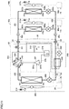
- Fig. 11 is a block diagram illustrating the configuration of a refrigerant circuit in a refrigeration cycle apparatus according to the second embodiment.
- an accumulator 218 is disposed in place of high-pressure receiver 204 in the configuration according to the second embodiment.
- Accumulator 218 is disposed on suction side 201b of compressor 201 and serves to isolate the refrigerant in a liquid state and accumulates the isolated refrigerant therein.
- Accumulator 218 is connected through a pipe 223 to port E of four-way valve 202 and connected through a pipe 225 to suction side 201b of compressor 201. Thereby, in the operation of compressor 201, only the refrigerant in a gaseous state is supplied from accumulator 218 to suction side 201b of compressor 201.
- accumulator 218 corresponds to one example of an "accumulation mechanism" of the refrigerant.
- accumulation mechanism both high-pressure receiver 204 ( Fig. 1 ) and accumulator 218 can be disposed.
- bypass mechanism 240 can be further provided, which extends from pipe 221 through which refrigerant in a liquid state flows.
- Bypass mechanism 240 includes a bypass pipe 241, an expansion valve 242, and an inside heat exchanger 243.
- Bypass pipe 241 is disposed such that the refrigerant having passed through outdoor heat exchanger 203 is routed, during the cooling operation, to a refrigerant inlet of accumulator 218 from the refrigerant path (pipe 221) through which the refrigerant is delivered to indoor unit 40.
- An expansion valve 242 is provided at some midpoint in bypass pipe 241.
- An electronic expansion valve (LEV) having a degree of opening that is electronically controlled according to the command from outdoor unit controller 30 is applicable to expansion valve 242.
- Inside heat exchanger 243 is configured to perform heat exchange between the refrigerant flowing through bypass pipe 241 and the refrigerant flowing through pipe 221 in the refrigerant circuit.
- opening expansion valve 242 the degree of opening > 0
- a bypass path for refrigerant is formed so as to extend through inside heat exchanger 243 to accumulator 218.
- the degree of opening the amount of refrigerant that passes through the bypass path can be adjusted.
- the refrigerant bypass path extending through bypass pipe 241 can be interrupted.
- bypass mechanism 240 During the operation of the refrigeration cycle apparatus, formation of a refrigerant bypass path by bypass mechanism 240 leads to heat exchange in inside heat exchanger 243, so that liquefaction of the refrigerant that flows through pipe 221 can be promoted. Thereby, refrigerant noise can be suppressed while pressure loss can be suppressed.
- the termination condition and the abnormality detection condition for the refrigerant recovery operation can be set as described in the first embodiment, assuming that low-pressure detection value PI by pressure sensor 210 disposed in the same manner as in Fig. 1 is defined as the "state amount".
- the termination condition and the abnormality detection condition for the refrigerant recovery operation is, in one alternative according to the present invention, be set assuming that the refrigerant gas concentration detected by refrigerant leakage sensor 70 is defined as the "state amount" or, in an other alternative according to the present invention, assuming that degree of supercooling SC calculated from the detection values of pressure sensor 212 and temperature sensor 213 that are disposed in the same manner as in Fig. 8 is defined as the "state amount”.
- suction side 201b of compressor 201 is to be connected to the indoor unit 40 side through accumulator 218. Accordingly, even when on-off valve 211 is not disposed, four-way valve 202 controlled to bring about state 2 can form an "interruption mechanism" after the end of the refrigerant recovery operation. In other words, arrangement of on-off valve 211 corresponding to the "second interruption mechanism" does not have to be provided. In this case, in step S200 in Fig. 3 , four-way valve 202 is controlled to bring about state 2 (heating operation state) in place of closing of on-off valve 211.
- compressor 201 is configured so as to structurally interrupt the refrigerant path inside compressor 201, which can eliminate the need to dispose on-off valve 211. In this case, the process in step S200 in Fig. 3 is not required.
- the termination condition and the abnormality detection condition for the refrigerant recovery operation that is automatically started upon detection of a leakage of the refrigerant in the refrigeration cycle apparatus according to the first embodiment is applicable without limiting the configuration of the refrigerant circuit to the basic configuration shown in Fig. 2 .
- Fig. 12 is a block diagram illustrating the first configuration example of an air conditioning system according to the third embodiment.
- control of the refrigeration cycle apparatus having been described in the first and second embodiments can also be implemented by a part of a general building system controller 130 for a room in a building as a target space 60.
- Building system controller 130 includes an air conditioning controller 131, a lighting controller 132 and a ventilation controller 133. According to the command to air conditioning system controller 10, air conditioning controller 131 adjusts the air temperature in target space 60 by the cooling function and the heating function performed by the refrigeration cycle apparatus ( Figs. 2 and the like) including outdoor unit 20 and indoor units 40a and 40b.
- lighting controller 132 controls a lighting device (not shown) disposed in target space 60 to be turned on and off and also controls the intensity of illumination when the lighting device is turned on.
- ventilation controller 133 controls the operation of the ventilating device (not shown) disposed in target space 60 to be started and stopped.
- each of the functions of air conditioning controller 131, lighting controller 132 and ventilation controller 133 can be implemented as part of the control function implemented by a microcomputer.
- air conditioning system controller 10 can also control the refrigeration cycle apparatus according to the instruction from air conditioning controller 131.
- the refrigerant recovery operation having been described in the first embodiment (including a modification thereof) and the second embodiment can also be performed as part of air conditioning control by building system controller 130.
- air conditioning system controller 10 (a computer), outdoor unit controller 30, indoor unit controller 50, and air conditioning controller 131 can form controller 101 for the refrigeration cycle apparatus.
- information output unit 105 for a user interface that has been described in the first embodiment (including a modification thereof) and the second embodiment is disposed also in building system controller 130.
- building system controller 130 can further include a refrigerant leakage sensing unit 134.
- Refrigerant leakage sensing unit 134 can receive an output signal from refrigerant leakage sensor 70 through radio communication or through a signal line. In this case, refrigerant leakage sensing unit 134 detects a leakage of refrigerant in target space 60. Detection of a leakage of refrigerant is transmitted from refrigerant leakage sensing unit 134 through air conditioning system controller 10 to outdoor unit controller 30 and indoor unit controller 50. Thereby, the refrigerant recovery operation having been described in the first embodiment (including a modification thereof) and the second embodiment can be performed.
- Fig. 13 is a block diagram illustrating the second configuration example of the air conditioning system according to the third embodiment.
- a remote controller (which will be hereinafter also referred to as an "indoor remote controller") is disposed as a user interface in target space 60.
- Indoor remote controller 110 can be provided with a display unit 115 such as a liquid crystal panel and a speaker (not shown). By display unit 115 and the speaker as described above, information output unit 105 for outputting a message in at least one of a visual manner and an auditory manner to a user can be disposed in indoor remote controller 110. In addition, a plurality of indoor remote controllers 110 may be disposed in the same target space 60.
- controller 101 of the refrigeration cycle apparatus can be formed of a microcomputer (not shown) in indoor remote controller 110, outdoor unit controller 30 and indoor unit controller 50 in place of air conditioning system controller 10. Furthermore, the output signal from refrigerant leakage sensor 70 can be input into indoor remote controller 110. Alternatively, through an electrical connection via a signal line 91 between refrigerant leakage sensor 70 and indoor unit controller 50 (50a, 50b), the output signal from refrigerant leakage sensor 70 may be transmitted from indoor unit controller 50 to indoor remote controller 110 and outdoor unit controller 30.
- the output signal from refrigerant leakage sensor 70 may be transmitted from outdoor unit controller 30 to indoor unit controller 50 (50a, 50b) and indoor remote controller 110.
- a plurality of refrigerant leakage sensors 70 may be disposed in one target space 60.
- the refrigerant recovery operation is started.
- the functions are shared among air conditioning system controller 10, outdoor unit controller 30, indoor unit controller 50, and indoor remote controller 110, so that the main control unit thereof (controller 101) can be configured in any manner.
- the first embodiment itself does not form part of the invention.
- any number of outdoor units 20 may be disposed while any number of indoor units 40 may be disposed.
- a plurality of outdoor units 20 can be provided.
- the number of indoor units 40 disposed so as to correspond to the number of outdoor units 20 is not limited to two, but may be one or may be any number.
- the number of target spaces 60 and the number of indoor units 40 disposed in target space 60 may be one or may be any number.
Description
- The present invention relates to a refrigeration cycle apparatus, and particularly to a refrigeration cycle apparatus having a function of detecting a leakage of refrigerant.
- In a refrigeration cycle apparatus, air conditioning is performed by heat exchange accompanied with liquefaction (condensation) and vaporization (evaporation) of circulating refrigerant that is sealed therein.
Japanese Patent Laying-Open No. 2002-228281 PTL 1 discloses a refrigeration cycle apparatus equipped with an outdoor unit and at least one indoor unit, the refrigeration cycle apparatus comprising: a compressor; an outdoor heat exchanger provided in the outdoor unit;an indoor heat exchanger provided in the indoor unit; a refrigerant pipe configured to connect the compressor, the outdoor heat exchanger, and the indoor heat exchanger in a circulation manner; a first interruption mechanism provided in a path that connects the outdoor heat exchanger and the indoor heat exchanger without passing through the compressor in a refrigerant circulation path that has the compressor, the outdoor heat exchanger, the indoor heat exchanger, and the refrigerant pipe; a leakage sensor configured to detect a leakage of refrigerant that flows through the refrigerant pipe; an information output unit configured to output information to a user; and a controller configured to perform a refrigerant recovery operation, wherein the controller is configured to perform the refrigerant recovery operation when the leakage sensor detects a leakage of the refrigerant until a termination condition based on a predetermined state amount is satisfied, in the refrigerant recovery operation, the first interruption mechanism interrupts a flow of the refrigerant and the compressor is operated in a state where the refrigerant circulation path is formed in a direction in which the refrigerant discharged from the compressor passes through the outdoor heat exchanger and subsequently passes through the indoor heat exchanger. The leakage sensor is configured to detect a refrigerant concentration of the refrigerant in atmosphere. The refrigeration cycle apparatus further comprises a pressure detector disposed on a discharge side of the compressor; and an accumulation mechanism in which the refrigerant in a liquid state is accumulated, the accumulation mechanism being disposed between the outdoor heat exchanger and the first interruption mechanism in the refrigerant circulation path. - The similar refrigerant recovery operation (a pump down operation) is disclosed also in
Japanese Patent Laying-Open No. 2016-11783 Japanese Patent Laying-Open No. 2013-122364 Japanese Patent Laying-Open No. 2004- 286315 - Further prior art useful for understanding the technological background of the present application is disclosed in documents
WO 2016/170651 A1 (PLT 5) andUS 2016/091241 A1 (PLT 6). -
- PTL 1 :
Japanese Patent Laying-Open No. 2002-228281 - PTL 2 :
Japanese Patent Laying-Open No. 2016-11783 - PTL 3 :
Japanese Patent Laying-Open No. 2013-122364 - PTL 4 :
Japanese Patent Laying-Open No. 2004-286315 - PTL 5:
WO 2016/170651 A1 - PTL 6 :
US 2016/091241 A1 - According to the disclosure in
PTL 1, during recovery of refrigerant, when a pressure detector disposed downstream of an on-off valve located downstream of a receiver tank detects a prescribed pressure in a cooling operation, the compressor is stopped to end the pump down operation. - However,
PTL 1 to PTL 4 each disclose the termination condition for the pump down operation but do not particularly disclose abnormality detection performed until the termination condition is satisfied by a pressure decrease or the like resulting from recovery of refrigerant. - Accordingly, when a certain abnormality, for example, a failure or the like in a compressor, an outdoor blower fan, a pressure detector, or an on-off valve occurs during a pump down operation, the recovery of refrigerant is not normally completed. Thus, the pump down operation may be continuously performed while the termination condition remains unsatisfied. Such a situation may cause a concern that a user cannot be appropriately notified about an abnormality.
- The present invention has been made to solve the above-described problems. An object of the present invention is to provide appropriate user guidance in a refrigerant recovery operation started upon detection of a leakage of refrigerant in a refrigeration cycle apparatus including a refrigerant leakage sensor.
- Embodiments of the present invention provide refrigeration cycle apparatuses according to the independent claims. Subsequently described aspects and embodiments of the present application are to be considered to be embodiments of the present invention only if they fall within the scope of one of the independent claims.
- In an aspect of the present invention, a refrigeration cycle apparatus equipped with an outdoor unit and at least one indoor unit includes: a compressor; an outdoor heat exchanger provided in the outdoor unit; an indoor heat exchanger provided in the indoor unit; a refrigerant pipe; a first interruption mechanism; a leakage sensor for refrigerant; and an information output unit configured to output information to a user. The refrigerant pipe is configured to connect the compressor, the outdoor heat exchanger, and the indoor heat exchanger. The first interruption mechanism is provided in a path that connects the outdoor heat exchanger and the indoor heat exchanger without passing through the compressor in a refrigerant circulation path that has the compressor, the outdoor heat exchanger, the indoor heat exchanger, and the refrigerant pipe. The leakage sensor is configured to detect a leakage of refrigerant that flows through the refrigerant pipe. When the leakage sensor detects a leakage of the refrigerant, a refrigerant recovery operation is performed until a termination condition based on a predetermined state amount is satisfied. In the refrigerant recovery operation, the first interruption mechanism interrupts a flow of the refrigerant and the compressor is operated in a state where the refrigerant circulation path is formed in a direction in which the refrigerant discharged from the compressor passes through the outdoor heat exchanger and subsequently passes through the indoor heat exchanger. When an abnormality in the refrigerant recovery operation is detected during the refrigerant recovery operation, the information output unit outputs guidance information for notifying the user about the abnormality.
- According to the present invention, appropriate user guidance is provided in a refrigerant recovery operation started upon detection of a leakage of refrigerant in a refrigeration cycle apparatus including a refrigerant leakage sensor.
-
-
Fig. 1 is a block diagram illustrating the configuration of an air conditioning system to which a refrigeration cycle apparatus according to an embodiment of the present disclosure is applied. However, this embodiment does not include all the features of the invention, as alternatively set out inindependent claims 1 and 3. -
Fig. 2 is a block diagram illustrating the configuration of a refrigerant circuit in the refrigeration cycle apparatus according to the first embodiment, the first embodiment itself not forming part of the invention. -
Fig. 3 is a flowchart illustrating a control process in an operation of the refrigeration cycle apparatus. -
Fig. 4 is a conceptual diagram illustrating an example of a behavior of a low-pressure detection value in a refrigerant recovery operation. -
Fig. 5 is a conceptual diagram illustrating variable setting of a reference time period and a reference change characteristic about a change in the low-pressure detection value in the refrigerant recovery operation. -
Fig. 6 is a conceptual diagram illustrating variable setting for a temperature condition with respect to the reference change characteristic and the reference time period about a change in the low-pressure detection value. -
Fig. 7 is a conceptual diagram illustrating variable setting for an amount of sealed refrigerant with respect to the reference change characteristic and the reference time period about a change in the low-pressure detection value. -
Fig. 8 is a block diagram illustrating the configuration of a refrigerant circuit in a refrigeration cycle apparatus according to a modification of the first embodiment. -
Fig. 9 is a conceptual diagram illustrating an example of a behavior of the degree of supercooling in the refrigerant recovery operation. -
Fig. 10 is a conceptual diagram illustrating an example of a behavior of a refrigerant gas concentration in the refrigerant recovery operation. -
Fig. 11 is a block diagram illustrating the configuration of a refrigerant circuit in a refrigeration cycle apparatus according to the second embodiment. -
Fig. 12 is a block diagram illustrating the first configuration example of an air conditioning system according to the third embodiment. -
Fig. 13 is a block diagram illustrating the second configuration example of the air conditioning system according to the third embodiment. - The embodiments of the present application will be hereinafter described in detail with reference to the accompanying drawings. In the following description, the same or corresponding components in the accompanying drawings will be designated by the same reference characters, and description thereof will not be basically repeated.
-
Fig. 1 is a block diagram illustrating the configuration of an air conditioning system to which a refrigeration cycle apparatus according to the present embodiment is applied. The first embodiment does not fall within the scope of the invention, as defined in the appended claims. - Referring to
Fig. 1 , anair conditioning system 100 includes anoutdoor unit 20, a plurality ofindoor units refrigerant pipe 80.Indoor units target space 60 for air conditioning. Targetspace 60 is a living room in a house, a building or the like, for example.Refrigerant pipe 80 is formed of a copper pipe, for example, and connectsoutdoor unit 20 toindoor units -
Outdoor unit 20 includes anoutdoor unit controller 30.Indoor units indoor unit controllers outdoor unit controller 30 andindoor unit controllers -
Air conditioning system 100 further includes an airconditioning system controller 10. Airconditioning system controller 10 can be formed of a remote controller into which a user command can be input. Examples of the user command may include commands to start and stop an operation, a command to set a timer operation, a command to select an operation mode, a command to set a temperature, and the like. - For example, air
conditioning system controller 10 can be disposed intarget space 60 or an operation management room in which a maintenance manager stays for centralized control of the plurality oftarget spaces 60. Airconditioning system controller 10 can be configured such that a user (for example, including a maintenance manager and a serviceman) can input, thereinto, not only the command to operateoutdoor unit 20 orindoor units - The microcomputer (not shown) stored in air
conditioning system controller 10 is configured to be capable of bidirectionally transmitting and receiving data to and fromoutdoor unit controller 30,indoor unit controllers conditioning system controller 10 includes aninformation output unit 15 configured to output a message in at least one of a visual manner and an auditory manner for notifying a user about information.Information output unit 15 is configured, for example, to include at least one of a display screen such as a liquid crystal panel and a speaker. The operation ofinformation output unit 15 is controlled by the microcomputer of airconditioning system controller 10. For example,information output unit 15 is provided on the surface or on the outside of the remote controller. - Furthermore, an
information output unit 35 similar toinformation output unit 15 can be disposed so as to correspond tooutdoor unit 20. Similarly,information output units indoor units information output unit 35 can be controlled byoutdoor unit controller 30. The operation of information output unit 45 (45a,45b) can be controlled byindoor unit controllers information output unit 105. Specifically, in the refrigeration cycle apparatus according to the present embodiment, at least oneinformation output unit 105 is disposed so as to correspond to at least any one of airconditioning system controller 10,outdoor unit controller 30, andindoor unit controllers - Furthermore, the function of controlling each component of the refrigeration cycle apparatus according to the present embodiment is shared among air
conditioning system controller 10,outdoor unit controller 30, andindoor unit controllers conditioning system controller 10,outdoor unit controller 30, andindoor unit controllers controller 101. - A
refrigerant leakage sensor 70 is disposed intarget space 60 for air conditioning.Refrigerant leakage sensor 70 detects the refrigerant gas concentration in atmosphere for the refrigerant used in the refrigeration cycle apparatus, in one alternative of the invention. In this alternative of the invention,refrigerant leakage sensor 70 is configured to output a detection signal when the refrigerant gas concentration increases above a predetermined reference value. Alternatively, outside the invention, for detecting a decrease in the oxygen concentration caused by an increase in the refrigerant gas concentration,refrigerant leakage sensor 70 may be configured to output a detection signal when the oxygen concentration decreases below a reference value. The output fromrefrigerant leakage sensor 70 is transmitted toindoor unit controllers outdoor unit controller 30, and airconditioning system controller 10. - In the following explanation,
indoor units indoor units indoor unit controllers indoor unit controllers - In the configuration example in
Fig. 1 ,indoor units common target space 60, but a plurality of indoor units 40 may be disposed in different target spaces. In this case, it is preferable thatrefrigerant leakage sensor 70 is disposed in each target space.Refrigerant leakage sensor 70 can also be disposed in a duct or the like (not shown). Thus,refrigerant leakage sensor 70 can be disposed at any position without being limited to a position insidetarget space 60 as long as it can detect the refrigerant gas concentration. -
Fig. 2 is a block diagram illustrating the configuration of a refrigerant circuit in the refrigeration cycle apparatus according to the first embodiment, the first embodiment itself not forming part of the invention. - Referring to
Fig. 2 , the refrigeration cycle apparatus includes anoutdoor unit 20 provided with: acompressor 201; a four-way valve 202; anoutdoor heat exchanger 203; a high-pressure receiver 204; anoutdoor fan 205; anoutdoor expansion valve 206; an on-offvalve 211; andpipes 220 to 224.Compressor 201, four-way valve 202,outdoor heat exchanger 203, high-pressure receiver 204, andoutdoor expansion valve 206 are connected in this order throughpipes 220 to 224. Also,refrigerant pipe 80 shown inFig. 1 includesrefrigerant pipes -
Compressor 201 is configured to be capable of changing an operation frequency by the control signal fromoutdoor unit controller 30. By changing the operation frequency ofcompressor 201, the output from the compressor is adjusted.Compressor 201 may be of various types, for example, such as a rotary type, a reciprocating type, a scroll type, and a screw type as appropriate. Four-way valve 202 has ports E, F, G, and H.Outdoor heat exchanger 203 has ports P3 and P4. - The refrigeration cycle apparatus includes indoor unit 40 (40a, 40b) provided with: an indoor heat exchanger 207 (207a, 207b); an indoor fan 208 (208a, 208b); and an indoor expansion valve 209 (209a, 209b).
Pipe 231,indoor heat exchanger 207a,indoor expansion valve 209a, andpipe 232 are connected in this order whilepipe 231,indoor heat exchanger 207b,indoor expansion valve 209b, andpipe 232 are connected in this order.Indoor heat exchanger 207a andindoor expansion valve 209a are connected in parallel withindoor heat exchanger 207b andindoor expansion valve 209b.Indoor heat exchanger 207a has ports P1a and P2a.Indoor heat exchanger 207b has ports P1b and P2b. - Each of
outdoor expansion valve 206 andindoor expansion valves outdoor expansion valve 206 is controlled byoutdoor unit controller 30, for example, so as to include degrees to be fully opened and fully closed. - In indoor unit 40, indoor unit controller 50 (50a, 50b) controls: the operation of indoor fan 208 (208a, 208b) to be stopped and started; and the rotation speed of indoor fan 208 (208a, 208b) during the operation. Furthermore, in
outdoor unit 20,outdoor unit controller 30 controls: the operation ofcompressor 201 to be stopped and started; the frequency ofcompressor 201 during the operation; the operation ofoutdoor fan 205 to be stopped and started; the rotation speed ofoutdoor fan 205 during the operation; the state of four-way valve 202; and on-offvalve 211 to be opened or closed. - In
outdoor unit 20,pipe 220 connects port H of four-way valve 202 and a gas-side refrigerantpipe connection hole 21 ofoutdoor unit 20.Pipe 220 is provided with on-offvalve 211. On the outside ofoutdoor unit 20, one end ofrefrigerant pipe 80x is connected to gas-side refrigerantpipe connection hole 21. The other end ofrefrigerant pipe 80x is connected throughpipe 231 on the indoor unit 40 side to port P1a on one side ofindoor heat exchanger 207a and port P1b on one side ofindoor heat exchanger 207b. - On the inside of indoor unit 40, indoor heat exchanger 207 and indoor expansion valve 209 are connected in series between
pipes Fig. 2 ,indoor heat exchanger 207a andindoor expansion valve 209a are connected betweenpipes indoor unit 40a whileindoor heat exchanger 207b andindoor expansion valve 209b are connected betweenpipes indoor unit 40b.Pipe 232 of indoor unit 40 is connected throughrefrigerant pipe 80y to a liquid-side refrigerantpipe connection hole 22 of the outdoor unit. - In
outdoor unit 20,pipe 221 connects liquid-side refrigerantpipe connection hole 22 of the outdoor unit and port P4 ofoutdoor heat exchanger 203.Pipe 221 is provided with high-pressure receiver 204 andoutdoor expansion valve 206. High-pressure receiver 204 is connected between port P4 andoutdoor expansion valve 206. -
Pipe 222 connects port P3 ofoutdoor heat exchanger 203 and port F of four-way valve 202.Pipe 223 connects port E of four-way valve 202 and asuction side 201b ofcompressor 201.Pipe 224 connects adischarge side 201a ofcompressor 201 and port G of four-way valve 202. In this way, refrigerant pipe 80 (80x, 80y) andpipes 220 to 225, 231, and 232 can constitute a "refrigerant pipe" through whichcompressor 201,outdoor heat exchanger 203, and indoor heat exchanger 207 are connected in a circulation manner. - On
pipe 223, apressure sensor 210 for detecting the pressure on the suction side (the low-pressure side) ofcompressor 201 is disposed. A detection value PI by pressure sensor 210 (hereinafter also referred to as a low-pressure detection value PI) is input intooutdoor unit controller 30. -
Outdoor unit 20 is provided with atemperature sensor 214 for detecting an atmospheric temperature. Similarly,indoor units temperature sensors temperature sensor 214 is input intooutdoor unit controller 30. Detection temperatures Tra and Trb bytemperature sensors indoor unit controllers - Then, a refrigerant circulation path in the refrigeration cycle apparatus will be described.
- Four-
way valve 202 is controlled by the signal fromoutdoor unit controller 30 to bring about the first state (cooling operation state: state 1) and the second state (heating operation state: state 2). In the first state, port G is in communication with port F while port E is in communication with port H. In the second state, port G is in communication with port H while port E is in communication with port F. In other words, port E corresponds to the "first port", port F corresponds to the "second port", port G corresponds to the "third port", and port H corresponds to the "fourth port". - When
compressor 201 is operated while four-way valve 202 is in state 1 (cooling operation state), the refrigerant circulation path is formed in the direction indicated by solid line arrows inFig. 2 . Specifically, the refrigerant that has been changed into high-temperature, high-pressure vapor bycompressor 201 is condensed (liquefied) as a result of heat radiation inoutdoor heat exchanger 203 when the refrigerant flows throughpipes outdoor heat exchanger 203. The condensed refrigerant passes throughpipe 221, high-pressure receiver 204, andoutdoor expansion valve 206, and then passes throughrefrigerant pipe 80y so as to be delivered to indoor unit 40. - In indoor unit 40, the refrigerant is evaporated (vaporized) as a result of heat absorption in indoor heat exchanger 207 when the refrigerant flows through
pipe 232 and indoor expansion valve 209 and then passes through indoor heat exchanger 207. The vaporized refrigerant flows throughpipe 231,refrigerant pipe 80x andpipes suction side 201b ofcompressor 201. Thereby, target space 60 (Fig. 1 ) in whichindoor units - In other words, in the cooling operation state, a refrigerant circulation path is formed in the direction in which the refrigerant discharged from
compressor 201 passes throughoutdoor heat exchanger 203 and subsequently passes through indoor heat exchanger 207. - On the other hand, in state 2 (heating operation state), the refrigerant circulation path is formed in the direction indicated by dotted line arrows in
Fig. 2 . Specifically, the refrigerant that has been changed into high-temperature, high-pressure vapor bycompressor 201 flows frompipes refrigerant pipe 80x so as to be delivered to indoor unit 40. In indoor unit 40, the refrigerant in a vapor state is condensed (liquefied) as a result of heat radiation in indoor heat exchanger 207 when the refrigerant flows throughpipe 231 and passes through indoor heat exchanger 207. The condensed refrigerant flows through indoor expansion valve 209 andpipe 232 and passes throughrefrigerant pipe 80y so as to be delivered tooutdoor unit 20. - In
outdoor unit 20, the refrigerant is evaporated (vaporized) as a result of heat absorption inoutdoor heat exchanger 203 when the refrigerant flows throughpipe 221,outdoor expansion valve 206 and high-pressure receiver 204 and then passes throughoutdoor heat exchanger 203. The vaporized refrigerant flows throughpipes suction side 201b ofcompressor 201. Thereby, target space 60 (Fig. 1 ) in whichindoor units - In each of state 1 (cooling operation state) and state 2 (heating operation state),
outdoor expansion valve 206 is provided in a path that connectsoutdoor heat exchanger 203 and indoor heat exchanger 207 without passing throughcompressor 201 in the refrigerant circulationpath including compressor 201,outdoor heat exchanger 203, indoor heat exchanger 207, andrefrigerant pipes outdoor unit controller 30 controlsoutdoor expansion valve 206 to be fully closed, so that the "first interruption mechanism" can be formed. Alternatively, a valve (representatively, an on-off valve) for forming the "first interruption mechanism" can also be disposed onpipe 221 orrefrigerant pipe 80y. In this way, the "first interruption mechanism" has a function of interrupting the flow of the refrigerant in a liquid state on the refrigerant circulation path. - The following is an explanation about control performed upon detection of a leakage of refrigerant by
refrigerant leakage sensor 70 in the refrigeration cycle apparatus according to the first embodiment. -
Fig. 3 is a flowchart illustrating a control process in the operation of the refrigeration cycle apparatus. The control process shown inFig. 3 can be cooperatively performed by airconditioning system controller 10,outdoor unit controller 30, and indoor unit controller 50, for example. Accordingly, each of the steps shown inFig. 3 will be described below as being performed bycomprehensive controller 101. - Referring to
Fig. 3 , when acontroller 101 receives a command to start the operation of the air conditioning system in step S100,controller 101 starts the air conditioning operation by the refrigeration cycle apparatus shown inFig. 2 in step S110. When an instruction to perform a cooling operation is given,compressor 201 is operated in the state wherecontroller 101 controls four-way valve 202 to bring aboutstate 1, thereby forming a refrigerant circulation path. In contrast, when an instruction to perform a heating operation is given,compressor 201 is operated in the state wherecontroller 101 controls four-way valve 202 to bring aboutstate 2, thereby forming a refrigerant circulation path. The operation of each element inoutdoor unit 20 and indoor unit 40 is controlled such that the operation commands such as a setting temperature are satisfied. - Based on the output from
refrigerant leakage sensor 70,controller 101 monitors whether refrigerant leaks or not intarget space 60 during the operation of the air conditioning system. Whenrefrigerant leakage sensor 70 does not output a detection signal about a leakage of refrigerant, it is determined as NO in step S120. Then, the air conditioning operation according to an operation command is continued. - When
refrigerant leakage sensor 70 outputs a detection signal, it is determined as YES in step S120, andcontroller 101 starts the process subsequent to step S130. - In step S130, using
information output unit 105,controller 101 notifies the user that a leakage of refrigerant occurs intarget space 60 in whichrefrigerant leakage sensor 70 is disposed. In this case, it is preferable thatinformation output unit 105 that outputs a message in at least one of a visual manner and an auditory manner includes information output units 45 inindoor units - Furthermore, in step S140, the controller determines whether the refrigeration cycle apparatus is performing the heating operation or not. When the refrigeration cycle apparatus is performing the heating operation (determined as YES in S140), the controller switches four-
way valve 202 to bring about state 1 (the cooling operation state) in step S150. On the other hand, when the refrigeration cycle apparatus is performing the cooling operation (determined as NO in step S140), four-way valve 202 is maintained in state 1 (the cooling operation state). Thereby, when a leakage of refrigerant is detected, a refrigerant circulation path in the cooling operation is formed, that is, a refrigerant circulation path is formed in the direction in which the refrigerant discharged fromcompressor 201 passes throughoutdoor heat exchanger 203 and subsequently passes through indoor heat exchanger 207. - In the state where the refrigerant circulation path in the cooling operation is formed,
controller 101 controlsoutdoor expansion valve 206 to be fully closed in step S160. Whencompressor 201 is continuously operated in the state whereoutdoor expansion valve 206 interrupts the path through which the refrigerant in a liquid state is delivered to indoor unit 40, the refrigerant recovery operation by the so-called pump down operation is performed. In step S170,controller 101 controls indoor expansion valve 209 to be fully opened in the refrigerant recovery operation. - Again referring to
Fig. 2 , in the refrigerant recovery operation, the refrigerant vaporized in indoor heat exchanger 207 is suctioned bycompressor 201 from indoor unit 40. Furthermore, the refrigerant in the high-temperature and high-pressure state discharged fromcompressor 201 is delivered tooutdoor heat exchanger 203 and condensed therein. Since the path to indoor unit 40 is interrupted, the condensed refrigerant is accumulated in a liquid state insideoutdoor heat exchanger 203 and in high-pressure receiver 204. Thereby, the refrigerant recovery operation for recovering refrigerant inoutdoor unit 20 can be implemented. - In the refrigerant recovery operation, the amount of refrigerant in a liquid state to be recovered in
outdoor unit 20 can be increased by disposing high-pressure receiver 204. In other words, high-pressure receiver 204 corresponds to one example of an "accumulation mechanism", according to an alternative of the present invention. In addition, without providing high-pressure receiver 204 in the configuration inFig. 2 , refrigerant can be stored mainly byoutdoor heat exchanger 203. - In the refrigerant recovery operation, it is preferable to promote evaporation (vaporization) in indoor heat exchanger 207 in order to increase the amount of refrigerant to be recovered. Thus, it is preferable that
indoor expansion valves indoor fans - Again referring to
Fig. 3 , during the refrigerant recovery operation,controller 101 determines in step S180 whether the termination condition for a predetermined state amount has been satisfied or not. - In the refrigerant recovery operation, as recovery of refrigerant progresses, the pressure on the low-pressure side of
compressor 201, that is, low-pressure detection value PI bypressure sensor 210 decreases. -
Fig. 4 is a conceptual diagram illustrating an example of a behavior of low-pressure detection value PI in the refrigerant recovery operation. InFig. 4 , the horizontal axis shows an elapsed time t from the timing at which the refrigerant recovery operation (the pump down operation) is started while the vertical axis shows low-pressure detection value PI at each point of time. - Referring to
Fig. 4 , as a behavior of low-pressure detection value PI with respect to elapsed time t, a pressure change characteristic fa(t) in a normal state and a pressure change characteristic fb(t) in an abnormal state are shown. - Each of pressure change characteristics fa(t) and fb(t) decreases over time from a pressure value P0 at the start of the refrigerant recovery operation (t = 0). However, when an abnormality occurs due to failures or the like in
compressor 201,outdoor fan 205,outdoor expansion valve 206, orpressure sensor 210, the change (decrease) in low-pressure detection value PI is reduced as compared with pressure change characteristic fa(t) in a normal state as shown by pressure change characteristic fb(t). - According to pressure change characteristic fa(t) in a normal state, low-pressure detection value PI decreases eventually to a final pressure (negative pressure) that is lower than atmospheric pressure. On the other hand, according to pressure change characteristic fb(t) in an abnormal state, low-pressure detection value PI stops to decrease in a region equal to atmospheric pressure or in a region higher than atmospheric pressure. Thus, when a reference value Ps is set to be greater than the above-mentioned final pressure in a normal state, the condition at the point of time of t = ts shows that PI < Ps in a normal state, whereas PI > Ps in an abnormal state. Thus, low-pressure detection value PI does not decrease below reference value Ps.
- Accordingly, the termination condition for the refrigerant recovery operation in step S180 in
Fig. 3 can be defined as being satisfied when low-pressure detection value PI decreases to predetermined reference value Ps. In other words, the termination condition can be set assuming that low-pressure detection value PI is defined as a "state amount". - Furthermore, in a normal state, low-pressure detection value PI decreases to reference value Ps at the point of time of t = t3. In this case, the time length until t3 or the time length having a margin until t3 is set as a reference time period ts. Thereby, when low-pressure detection value PI does not decrease to reference value Ps (hereinafter also referred to as "upon occurrence of timeout") at the point of t = ts (in other words, even when reference time period ts has elapsed), an abnormality in the refrigerant recovery operation can be detected. In other words, reference time period ts corresponds to the "first reference time period" or the "second reference time period".
- Alternatively, as indicated by a broken line in
Fig. 4 , reference change characteristic fr(t) can be set in advance, for example, between pressure change characteristics fa(t) and fb(t). Reference change characteristic fr(t) corresponds to the collection of reference pressure values at each elapsed time t from the start of the refrigerant recovery operation. For example, on reference change characteristic fr(t), Pl = P1 at the point of time of t = t1 while PI = P2 at the point of time of t = t2. Reference change characteristic fr(t) is set in a time period (t < ts) until reference time period ts has elapsed. - Thus, by comparing low-pressure detection value PI with the reference pressure value at each elapsed time, an abnormality in the refrigerant recovery operation can be detected before a lapse of reference time period ts. For example, in the case where PI > PI at the point of time of t = t1 or in the case where PI > P2 at the point of time of t = t2, an abnormality in the refrigerant recovery operation can be detected. In other words, an optional elapsed time (one or more) before a lapse of reference time period ts is set as the "third reference time period". In this case, when low-pressure detection value PI (that is, the "state amount") in the third reference time period is greater than the reference pressure value (that is, the "reference state amount"), an abnormality in the refrigerant recovery operation can be detected.
- In addition, reference change characteristic fr(t) can be defined not by the reference pressure value showing the pressure value itself but by the reference value about the degree of pressure change (degree of decrease) ΔP(t) from the start of the refrigerant recovery operation (which will be hereinafter referred to as the degree of reference pressure decrease). Degree of pressure decrease ΔP(t) at each point of time can be defined by the amount of pressure change (decrease) or the rate of pressure change (decrease) from an initial value P0 of low-pressure detection value PI.
- Reference change characteristic fr(t) corresponds to the collection of the degrees of reference pressure decrease at each elapsed time t from the start of the refrigerant recovery operation. While focusing attention on the fact that the degree of change (degree of decrease) ΔP of the pressure detection value is smaller in an abnormal refrigerant recovery operation than in a normal refrigerant recovery operation, an abnormality in the refrigerant recovery operation can be detected before a lapse of reference time period ts. In other words, also when the degree of pressure decrease ΔP(t) as the amount of decrease or as the rate of decrease of low-pressure detection value PI with respect to initial value P0 is smaller than the degree of reference pressure decrease, an abnormality in the refrigerant recovery operation can be detected.
- Alternatively, the reference change amount of low-pressure detection value PI per unit time is set. Thereby, when the change amount of low-pressure detection value PI per unit time is smaller than the reference change amount, an abnormality in the refrigerant recovery operation can also be detected. For example, the reference change amount can be set in accordance with reference change characteristic fr(t).
- Again referring to
Fig. 3 , when low-pressure detection value PI decreases to reference value Ps during the refrigerant recovery operation,controller 101 determines that the predetermined termination condition for low-pressure detection value PI as the "state amount" has been satisfied (determined as YES in S180), it ends the refrigerant recovery operation. In other words, the termination condition can be set by using low-pressure detection value PI as a predetermined "state amount". - Specifically, in step S190,
controller 101 stopscompressor 201 to end the refrigerant recovery operation. Then in step S200,controller 101 closes on-offvalve 211. Thereby, the refrigerant (in a liquid state) recovered inoutdoor unit 20 can be prevented from flowing back to indoor unit 40. In other words, on-offvalve 211 corresponds to one example of the "second interruption mechanism". - Further in step S210,
controller 101 notifies a user about completion (normal termination) of the refrigerant recovery operation and support therefor. Specifically,information output unit 105 outputs a message to a user. - When the termination condition is not satisfied during the refrigerant recovery operation (determined as NO in S180),
controller 101 determines in step S220 whether the abnormality detection condition for the refrigerant recovery operation has been satisfied or not. For example, upon occurrence of timeout as described above or upon detection that the degree of change ΔP with time of the pressure detection value as the "state amount" is smaller than the degree of change in accordance with reference change characteristic fr(t), the abnormality detection condition for the refrigerant recovery operation is satisfied, and thereby, it is determinate as YES in S220. In other words, an abnormality in the refrigerant recovery operation can be detected based on the behavior of low-pressure detection value PI as the "state amount", which appears until the termination condition is satisfied. On the other hand, the refrigerant recovery operation is continued while it is determined as NO both in steps S180 and S220. - When an abnormality in the refrigerant recovery operation is detected (determined as YES in S220),
controller 101 stopscompressor 201 to end the refrigerant recovery operation in the above-mentioned S190, and closes on-offvalve 211 in the above-mentioned step S200. - When the refrigerant recovery operation is ended as a result of detection of an abnormality,
controller 101 causes the process to proceed to step S230, in whichindoor expansion valves - In step S240,
controller 101 notifies the user about occurrence of an abnormality in the refrigerant recovery operation and support therefor. For example, in step S240,information output unit 105 can output: a message for notifying the user that "refrigerant may not have been appropriately recovered"; and a message for urging the user to "ventilate a room and make contact with a service company". - In this way, according to the refrigeration cycle apparatus in the first embodiment, when the abnormality detection condition related to the behavior of the low-pressure detection value as the "state amount" is satisfied due to a failure and the like in
compressor 201,outdoor fan 205,outdoor expansion valve 206, orpressure sensor 210 during the refrigerant recovery operation automatically started upon detection of a leakage of refrigerant, an abnormality in the refrigerant recovery operation can be detected. Then, upon detection of an abnormality, the refrigerant recovery operation is ended, andinformation output unit 105 outputs a message about occurrence of an abnormality and support therefor in at least one of a visual manner and an auditory manner. Thereby, appropriate user guidance can be implemented. - As shown in
Fig. 5 , reference time period ts and reference change characteristic fr(t) about a change in low-pressure detection value PI can also be variably set. -
Fig. 5 is a conceptual diagram for illustrating variable setting of reference time period ts and reference change characteristic fr(t) in accordance with the temperature condition and the amount of sealed refrigerant. - Referring to
Fig. 5 , a plurality of stages (A, B, C, ...) can be set as a temperature condition based on atmospheric temperatures Tot, Tra, and Trb detected bytemperature sensors - For reference change characteristic fr(t) and reference time period ts of low-pressure detection value PI, different characteristics and reference values can be set for each combination of the stage of the temperature condition and the stage of the amount of sealed refrigerant.
- In the example in
Fig. 5 , when the amount of sealed refrigerant is in a stage M1, reference change characteristic fr(t) can be set as different characteristics f11(t), f12(t), fl3(t), ... so as to correspond to stages A, B, and C, ..., respectively, of the temperature condition. Similarly, reference time period ts can be set at different values ts11, ts12, ts13, ... so as to correspond to stages A, B, and C, ..., respectively, of the temperature condition. - Similarly, when the amount of sealed refrigerant is in a stage M2 (smaller in amount than stage M1), reference change characteristic fr(t) can be set as different characteristics f21(t), f22(t), f23(t), ... so as to correspond to stages A, B, and C, ..., respectively, of the temperature condition. Similarly, reference time period ts can be set at different values ts21, ts22, ts23, ... so as to correspond to stages A, B, C, ..., respectively, of the temperature condition.
-
Fig. 6 is a conceptual diagram illustrating variable setting for the temperature condition with respect to reference change characteristic fr(t) and reference time period ts of low-pressure detection value P1. - Referring to
Fig. 6 , when the amount of sealed refrigerant is in stage M1 and when the temperature condition is in stage A (at a high temperature), setting is provided such that fr(t) = fl1(t) and ts = tsl1. In contrast, when the amount of sealed refrigerant is in the same stage M1 and when the temperature condition is in stage C (lower in temperature than stage A), setting is provided such that fr(t) = f13(t) and ts = ts13. - A change in low-pressure detection value PI during the refrigerant recovery operation becomes gentler at a high temperature than at a low temperature. Upon reflection of such a phenomenon, reference time period ts (ts11) at a high temperature (in stage A) is set to be longer than reference time period ts (ts13) at a low temperature (in stage C). Similarly, reference change characteristic fr(t) (f11(t)) at a high temperature (in stage A) is set to be smaller in degree of change ΔP(t) with time than reference change characteristic fr(t) (f13(t)) at a low temperature (in stage C).
- In other words, depending on the temperature condition, the variable setting can be performed such that, as the temperature is lower, reference time period ts is shorter and reference change characteristic fr(t) is greater in degree of change ΔP(t).
-
Fig. 7 illustrates variable setting for the amount of sealed refrigerant with respect to reference change characteristic fr(t) and reference time period ts of low-pressure detection value P1. - Referring to
Fig. 7 , when the amount of sealed refrigerant is in stage M1 and the temperature condition is in stage A, setting is provided such that fr(t) = f11(t) and ts = ts11. In contrast, when the temperature condition is in the same stage A and the amount of sealed refrigerant is in stage M2 (smaller in amount than M1), setting is provided such that fr(t) = f21(t) and ts = ts21. - A change in low-pressure detection value PI during the refrigerant recovery operation is gentler in the state of a larger amount of sealed refrigerant than in the state of a smaller amount of sealed refrigerant. Upon reflection of such a phenomenon, reference time period ts (ts11) in the state of a larger amount of sealed refrigerant (in stage M1) is set to be longer than reference time period ts (ts21) in the state of a smaller amount of sealed refrigerant (in stage M2). Similarly, reference change characteristic fr(t) (f11(t)) in the state of a larger amount of sealed refrigerant (in stage M1) is set to be smaller in degree of pressure change ΔP(t) with time than reference change characteristic fr(t) (f11(t)) in the state of a smaller amount of sealed refrigerant (in stage M2).
- In other words, depending on the amount of sealed refrigerant, the variable setting can be performed such that, as the amount of refrigerant is smaller, reference time period ts is shorter and reference change characteristic fr(t) is larger in degree of change ΔP(t).
- In this way, in the refrigerant recovery operation of the refrigeration cycle apparatus according to the first embodiment, the abnormality detection condition can be adjusted in accordance with the temperature condition and the amount of sealed refrigerant, so that erroneous detection of an abnormality can be prevented.
- As to the temperature condition, the stage can be selected based on the temperature detection values by
temperature sensors 214 and 215 shown inFig. 1 while one of the plurality of stages can be selected using the calendar function ofcontroller 101 from among the temperatures predicted based on date and month (season) or the combination of date and month (season) and time. - The modification of the first embodiment, the first embodiment itself not forming part of the invention, will be described below with regard to an example in which the "state amount" used for the termination condition and the abnormality detection condition for the refrigerant recovery operation is set to be different from low-pressure detection value PI (pressure sensor 210).
-
Fig. 8 is a block diagram illustrating the configuration of a refrigerant circuit in a refrigeration cycle apparatus according to an alternative of the present invention. - When comparing
Fig. 8 withFig. 1 , arrangement of the sensor in the refrigerant circuit is different. Specifically, temperature sensor 213 is disposed downstream (in the cooling operation state) ofoutdoor heat exchanger 203 and high-pressure receiver 204 whilepressure sensor 212 is disposed on the discharge side (the high-pressure side) ofcompressor 201.Pressure sensor 212 detects a high-pressure detection value Ph, which is then input intooutdoor unit controller 30. Similarly, temperature sensor 213 detects a refrigerant temperature Tq of the refrigerant in a liquid state, which is then input intooutdoor unit controller 30. The configuration of the refrigerant circuit according to the modification of the first embodiment is the same as that of the first embodiment (Fig. 2 ) except for arrangement of the sensor as described above. - Based on high-pressure detection value Ph and refrigerant temperature Tq,
outdoor unit controller 30 calculates the degree of supercooling (SC) of the accumulated refrigerant (in a liquid state). The degree of supercooling is defined by the value that is obtained by subtracting refrigerant temperature Tq detected by temperature sensor 213 from the value that is obtained by converting high-pressure detection value Ph ofpressure sensor 212 into a saturation temperature of the refrigerant. - In the refrigerant recovery operation, as the recovery of refrigerant progresses, the amount of refrigerant (in a liquid state) accumulated in outdoor unit 20 (
outdoor heat exchanger 203 and high-pressure receiver 204) increases, so that degree of supercooling SC rises accordingly. Thus, in the modification of the first embodiment, the termination condition and the abnormality detection condition for the refrigerant recovery operation are set assuming that not low-pressure detection value PI ofcompressor 201 but the degree of supercooling (SC) on the output side ofoutdoor heat exchanger 203 is defined as the "state amount". -
Fig. 9 is a conceptual diagram for illustrating a behavior of a change in degree of supercooling SC in the refrigerant recovery operation. InFig. 9 , the horizontal axis shows elapsed time t from the timing at which the refrigerant recovery operation (the pump down operation) is started while the vertical axis shows degree of supercooling SC at each point of time. - Referring to
Fig. 9 , according to SC change characteristic fsca(t) in a normal state, degree of supercooling SC eventually rises to a fixed saturation value. On the other hand, according to SC change characteristic fsca(t) in an abnormal state, degree of supercooling SC is saturated in a region lower than that in a normal state. Thus, when reference value SCs lower than the SC saturation value in a normal state is set, the condition at the point of time of t = ts shows that SC > SCs in a normal state, whereas SC < SCs in an abnormal state. Thus, degree of supercooling SC does not rise above reference value SCs. - Therefore, the termination condition for the refrigerant recovery operation in step S180 in
Fig. 3 can be defined as being satisfied when degree of supercooling SC, which is defined in place of low-pressure detection value PI as the "state amount", rises to predetermined reference value SCs. - Also, in a normal state, degree of supercooling SC rises to reference value SCs at the point of time of t = t3. Thus, the time length until t3 or the time length having a margin until t3 is set as reference time period ts. Thereby, when degree of supercooling SC does not rise to reference value SCs at the point of time of t = ts, an abnormality in the refrigerant recovery operation resulting from occurrence of timeout can be detected.
- Alternatively, while focusing attention on the fact that degree of change (degree of increase) ΔSC of degree of supercooling SC from the start of the refrigerant recovery operation becomes smaller in an abnormal state than in a normal state, an abnormality in the refrigerant recovery operation can be detected before a lapse of reference time period ts. Degree of increase ΔSC(t) at each point of time can be defined by the amount of change (increase) or the rate of increase (rise) about degree of supercooling SC from initial value SC0 at the start of the refrigerant recovery operation.
- As indicated by a broken line in
Fig. 9 , reference change characteristic fscr(t) can be set in advance, for example, between SC change characteristics fsca(t) and fscb(t). On reference change characteristic fscr(t), SC = SC1 at the point of time of t = t1 while SC = SC2 at the point of time of t = t2. Accordingly, in the case where SC < SC1 at the point of time of t = t1, degree of change ΔSC(t) with time of degree of supercooling SC is smaller than the degree of change in accordance with reference change characteristic fscr(t). Thus, an abnormality in the refrigerant recovery operation can be detected. Similarly, also in the case where SC < SC2 at the point of time of t = t2, an abnormality in the refrigerant recovery operation can be detected. - In other words, it can be determined that the termination condition for the refrigerant recovery operation in step S180 in
Fig. 3 is satisfied when degree of supercooling SC as the "state amount" rises to reference value SCs. Furthermore, it can be determined that the abnormality detection condition for the refrigerant recovery operation in step S220 inFig. 3 has been satisfied upon occurrence of timeout about degree of supercooling SC, or upon detection that degree of change ΔSC(t) with time of the degree of supercooling is smaller than the degree of change in accordance with reference change characteristic fscr(t). For example, when degree of supercooling SC (that is, the "state amount") in an optional elapsed time (that is, corresponding to the "third reference time period") before a lapse of reference time period ts is smaller than the reference value (that is, the "reference state amount") of the degree of supercooling in accordance with reference change characteristic fscr(t), an abnormality in the refrigerant recovery operation can be detected. Alternatively, by setting the reference change amount of degree of supercooling SC per reference unit time, an abnormality in the refrigerant recovery operation can also be detected when the change amount of degree of supercooling SC per unit time is smaller than the reference change amount. The reference change amount can be set in accordance with reference change characteristic fscr(t). - In addition, for the abnormality detection condition on which degree of supercooling SC is defined as the "state amount", reference time period ts and reference change characteristic fscr(t) can be set variably in accordance with the temperature condition and the amount of sealed refrigerant. Specifically, depending on the temperature condition, the variable setting can be performed such that, as the temperature is lower, reference time period ts is shorter and reference change characteristic fr(t) is larger in degree of change ΔP(t). Furthermore, depending on the amount of sealed refrigerant, the variable setting can be performed such that, as the amount of refrigerant is larger, reference time period ts is shorter and reference change characteristic fr(t) is larger in degree of change ΔP(t).
- Furthermore, it is understood that, in the refrigerant recovery operation, the refrigerant gas concentration detected by
refrigerant leakage sensor 70 decreases as recovery of the refrigerant progresses. Accordingly, in each of the configurations inFig. 2 andFig. 8 , the termination condition and the abnormality detection condition for the refrigerant recovery operation can be set assuming that the refrigerant gas concentration detected byrefrigerant leakage sensor 70 is defined as the "state value". As described above, the refrigerant gas concentration can be indirectly detected also by the oxygen concentration that lowers or rises as the refrigerant gas concentration rises or lowers.Refrigerant leakage sensor 70 is required to be configured to have a function of detecting the refrigerant gas concentration (or the oxygen concentration) in a quantitative value or in stages. -
Fig. 10 is a conceptual diagram for illustrating a behavior of a change in degree of a refrigerant gas concentration in the refrigerant recovery operation. InFig. 10 , the horizontal axis shows elapsed time t from the timing at which the refrigerant recovery operation (the pump down operation) is started while the vertical axis shows a refrigerant gas concentration v at each point of time. - Referring to
Fig. 10 , according to refrigerant concentration change characteristic fva(t) in a normal state, refrigerant gas concentration v eventually decreases below a predetermined reference value vs. On the other hand, according to refrigerant concentration change characteristic fvb(t) in an abnormal state, refrigerant gas concentration v does not decrease to reference value vs. Alternatively, as with refrigerant concentration change characteristic fvc(t), refrigerant gas concentration v may rise as refrigerant continuously leaks. - Accordingly, in a normal state, refrigerant gas concentration v decreases to reference value vs at the point of time of t = t3. In contrast, in an abnormal state, refrigerant gas concentration v does not decrease to reference value vs. Thus, the termination condition for the refrigerant recovery operation in step S180 in
Fig. 3 can be set to be satisfied when refrigerant gas concentration v, which is defined in place of low-pressure detection value PI as the "state amount", decreases to predetermined reference value vs. - Furthermore, the time length until t3 during which refrigerant gas concentration v decreases to reference value vs in a normal state or the time length having a margin until t3 is set as reference time period ts. Thereby, when refrigerant gas concentration v does not decrease to reference value vs at the point of time of t = ts, an abnormality in the refrigerant recovery operation resulting from occurrence of timeout can be detected.
- Alternatively, while focusing attention on the fact that degree of change (degree of decrease) Δv of refrigerant gas concentration v from the start of the refrigerant recovery operation is smaller in an abnormal state than in a normal state, an abnormality in the refrigerant recovery operation can also be detected before a lapse of reference time period ts. Degree of decrease Δv(t) at each point of time can be defined by the amount of change (decrease) or the rate of increase (decrease) of refrigerant gas concentration v from an initial value v0 at the start of the refrigerant recovery operation.
- As indicated by a broken line in
Fig. 10 , reference change characteristic fvr(t) can be set in advance, for example, between refrigerant concentration change characteristics fva(t) and fvb(t). On reference change characteristic fvr(t), v = v1 at the point of time of t = t1 while v = v2 at the point of time t = t2. Thus, in the case where v > v1 at the point of time of t = t1, degree of change Δv(t) with time of refrigerant gas concentration v is smaller than the degree of change in accordance with reference change characteristic fvr(t). Accordingly, an abnormality in the refrigerant recovery operation can be detected. Similarly, also in the case where v > v2 at the point of time of t = t2, an abnormality in the refrigerant recovery operation can be detected. - In other words, it can be determined that the termination condition for the refrigerant recovery operation in step S180 in
Fig. 3 has been satisfied when refrigerant gas concentration v as the "state amount" decreases to reference value vs. Furthermore, it can be determined that the abnormality detection condition for the refrigerant recovery operation in step S220 inFig. 3 has been satisfied upon occurrence of timeout for refrigerant gas concentration v, or upon detection that degree of change Δv(t) with time of the refrigerant gas concentration is smaller than the degree of change in accordance with reference change characteristic fvr(t). For example, when refrigerant gas concentration v (that is, the "state amount") in an optional elapsed time (that is, corresponding to the "third reference time period") before a lapse of reference time period ts is greater than the reference value (that is, the "reference state amount") of the refrigerant gas concentration in accordance with reference change characteristic fvr(t), an abnormality in the refrigerant recovery operation can be detected. Alternatively, by setting the reference change amount of refrigerant gas concentration v per unit time, an abnormality in the refrigerant recovery operation can also be detected when the change amount of refrigerant gas concentration v per unit time is smaller than the reference change amount. The reference change amount can be set in accordance with reference change characteristic fvr(t). - Also for the abnormality detection condition on which refrigerant gas concentration v is defined as the "state amount", reference time period ts and reference change characteristic fscr(t) can be set variably in accordance with the temperature condition and the amount of sealed refrigerant. Specifically, depending on the temperature condition, the variable setting can be performed such that, as the temperature is lower, reference time period ts is shorter and reference change characteristic fr(t) is larger in degree of change ΔP(t). Furthermore, depending on the amount of sealed refrigerant, the variable setting can be performed such that, as the amount of refrigerant is smaller, reference time period ts is shorter and reference change characteristic fr(t) is larger in degree of change ΔP(t).
- As having been described in the modification of the first embodiment, in the refrigeration cycle apparatus according to the present embodiment, normal termination of the refrigerant recovery operation and occurrence of an abnormality in the refrigerant recovery operation can be detected in the state where the state amount is selected as appropriate.
- The second embodiment will be hereinafter described with regard to a modification of the configuration of a refrigerant circuit in a refrigeration cycle apparatus.
-
Fig. 11 is a block diagram illustrating the configuration of a refrigerant circuit in a refrigeration cycle apparatus according to the second embodiment. - When comparing
Fig. 11 withFig. 1 , anaccumulator 218 is disposed in place of high-pressure receiver 204 in the configuration according to the second embodiment.Accumulator 218 is disposed onsuction side 201b ofcompressor 201 and serves to isolate the refrigerant in a liquid state and accumulates the isolated refrigerant therein.Accumulator 218 is connected through apipe 223 to port E of four-way valve 202 and connected through apipe 225 tosuction side 201b ofcompressor 201. Thereby, in the operation ofcompressor 201, only the refrigerant in a gaseous state is supplied fromaccumulator 218 tosuction side 201b ofcompressor 201. In the refrigerant recovery operation, the refrigerant in a liquid state can be accumulated inaccumulator 218. Thus,accumulator 218 corresponds to one example of an "accumulation mechanism" of the refrigerant. As an "accumulation mechanism", both high-pressure receiver 204 (Fig. 1 ) andaccumulator 218 can be disposed. - Furthermore, in the configuration in
Fig. 11 in which accumulator 218 is disposed, abypass mechanism 240 can be further provided, which extends frompipe 221 through which refrigerant in a liquid state flows.Bypass mechanism 240 includes abypass pipe 241, anexpansion valve 242, and aninside heat exchanger 243. -
Bypass pipe 241 is disposed such that the refrigerant having passed throughoutdoor heat exchanger 203 is routed, during the cooling operation, to a refrigerant inlet ofaccumulator 218 from the refrigerant path (pipe 221) through which the refrigerant is delivered to indoor unit 40. Anexpansion valve 242 is provided at some midpoint inbypass pipe 241. An electronic expansion valve (LEV) having a degree of opening that is electronically controlled according to the command fromoutdoor unit controller 30 is applicable toexpansion valve 242. - Inside
heat exchanger 243 is configured to perform heat exchange between the refrigerant flowing throughbypass pipe 241 and the refrigerant flowing throughpipe 221 in the refrigerant circuit. By opening expansion valve 242 (the degree of opening > 0), a bypass path for refrigerant is formed so as to extend throughinside heat exchanger 243 toaccumulator 218. Furthermore, by changing the degree of opening, the amount of refrigerant that passes through the bypass path can be adjusted. On the other hand, by closing expansion valve 242 (the degree of opening = 0: fully closed state), the refrigerant bypass path extending throughbypass pipe 241 can be interrupted. - During the operation of the refrigeration cycle apparatus, formation of a refrigerant bypass path by
bypass mechanism 240 leads to heat exchange ininside heat exchanger 243, so that liquefaction of the refrigerant that flows throughpipe 221 can be promoted. Thereby, refrigerant noise can be suppressed while pressure loss can be suppressed. - In the configuration in
Fig. 11 , the configurations of components other thanaccumulator 218 andbypass mechanism 240 in the refrigerant circuit are the same as those inFig. 2 , and therefore, the detailed description thereof will not be repeated. - Also in the configuration in which accumulator 218 is disposed, the termination condition and the abnormality detection condition for the refrigerant recovery operation can be set as described in the first embodiment, assuming that low-pressure detection value PI by
pressure sensor 210 disposed in the same manner as inFig. 1 is defined as the "state amount". - Alternatively, as having been described with respect to
Figure 1 , the termination condition and the abnormality detection condition for the refrigerant recovery operation is, in one alternative according to the present invention, be set assuming that the refrigerant gas concentration detected byrefrigerant leakage sensor 70 is defined as the "state amount" or, in an other alternative according to the present invention, assuming that degree of supercooling SC calculated from the detection values ofpressure sensor 212 and temperature sensor 213 that are disposed in the same manner as inFig. 8 is defined as the "state amount". - Furthermore, in the configuration shown in
Fig. 11 , when four-way valve 202 is controlled to bring about state 2 (the heating operation state),suction side 201b ofcompressor 201 is to be connected to the indoor unit 40 side throughaccumulator 218. Accordingly, even when on-offvalve 211 is not disposed, four-way valve 202 controlled to bring aboutstate 2 can form an "interruption mechanism" after the end of the refrigerant recovery operation. In other words, arrangement of on-offvalve 211 corresponding to the "second interruption mechanism" does not have to be provided. In this case, in step S200 inFig. 3 , four-way valve 202 is controlled to bring about state 2 (heating operation state) in place of closing of on-offvalve 211. - Alternatively, also in the configuration in
Fig. 1 ,compressor 201 is configured so as to structurally interrupt the refrigerant path insidecompressor 201, which can eliminate the need to dispose on-offvalve 211. In this case, the process in step S200 inFig. 3 is not required. - As having been described above in the second embodiment, the termination condition and the abnormality detection condition for the refrigerant recovery operation that is automatically started upon detection of a leakage of the refrigerant in the refrigeration cycle apparatus according to the first embodiment is applicable without limiting the configuration of the refrigerant circuit to the basic configuration shown in
Fig. 2 . - In the third embodiment, a modification of an air conditioning system will be described.
-
Fig. 12 is a block diagram illustrating the first configuration example of an air conditioning system according to the third embodiment. - Referring to
Fig. 12 , in the first configuration example of the air conditioning system according to the third embodiment, control of the refrigeration cycle apparatus having been described in the first and second embodiments can also be implemented by a part of a generalbuilding system controller 130 for a room in a building as atarget space 60. -
Building system controller 130 includes anair conditioning controller 131, alighting controller 132 and aventilation controller 133. According to the command to airconditioning system controller 10,air conditioning controller 131 adjusts the air temperature intarget space 60 by the cooling function and the heating function performed by the refrigeration cycle apparatus (Figs. 2 and the like) includingoutdoor unit 20 andindoor units - According to the instruction from the user,
lighting controller 132 controls a lighting device (not shown) disposed intarget space 60 to be turned on and off and also controls the intensity of illumination when the lighting device is turned on. According to the instruction from the user,ventilation controller 133 controls the operation of the ventilating device (not shown) disposed intarget space 60 to be started and stopped. In addition, each of the functions ofair conditioning controller 131,lighting controller 132 andventilation controller 133 can be implemented as part of the control function implemented by a microcomputer. - Consequently, as part of comprehensive building system control, air
conditioning system controller 10 can also control the refrigeration cycle apparatus according to the instruction fromair conditioning controller 131. In other words, the refrigerant recovery operation having been described in the first embodiment (including a modification thereof) and the second embodiment can also be performed as part of air conditioning control by buildingsystem controller 130. In the configuration example inFig. 12 , air conditioning system controller 10 (a computer),outdoor unit controller 30, indoor unit controller 50, andair conditioning controller 131 can formcontroller 101 for the refrigeration cycle apparatus. - In this case, it is preferable that
information output unit 105 for a user interface that has been described in the first embodiment (including a modification thereof) and the second embodiment is disposed also inbuilding system controller 130. - Alternatively,
building system controller 130 can further include a refrigerantleakage sensing unit 134. Refrigerantleakage sensing unit 134 can receive an output signal fromrefrigerant leakage sensor 70 through radio communication or through a signal line. In this case, refrigerantleakage sensing unit 134 detects a leakage of refrigerant intarget space 60. Detection of a leakage of refrigerant is transmitted from refrigerantleakage sensing unit 134 through airconditioning system controller 10 tooutdoor unit controller 30 and indoor unit controller 50. Thereby, the refrigerant recovery operation having been described in the first embodiment (including a modification thereof) and the second embodiment can be performed. -
Fig. 13 is a block diagram illustrating the second configuration example of the air conditioning system according to the third embodiment. - Referring to
Fig. 13 , in the first configuration example of the air conditioning system according to the third embodiment, in place of airconditioning system controller 10 inFig. 1 , a remote controller (which will be hereinafter also referred to as an "indoor remote controller") is disposed as a user interface intarget space 60. - Indoor remote controller 110 can be provided with a
display unit 115 such as a liquid crystal panel and a speaker (not shown). Bydisplay unit 115 and the speaker as described above,information output unit 105 for outputting a message in at least one of a visual manner and an auditory manner to a user can be disposed in indoor remote controller 110. In addition, a plurality of indoor remote controllers 110 may be disposed in thesame target space 60. - In the configuration example in
Fig. 13 ,controller 101 of the refrigeration cycle apparatus can be formed of a microcomputer (not shown) in indoor remote controller 110,outdoor unit controller 30 and indoor unit controller 50 in place of airconditioning system controller 10. Furthermore, the output signal fromrefrigerant leakage sensor 70 can be input into indoor remote controller 110. Alternatively, through an electrical connection via asignal line 91 betweenrefrigerant leakage sensor 70 and indoor unit controller 50 (50a, 50b), the output signal fromrefrigerant leakage sensor 70 may be transmitted from indoor unit controller 50 to indoor remote controller 110 andoutdoor unit controller 30. - Alternatively, through an electrical connection via a
signal line 92 betweenrefrigerant leakage sensor 70 andoutdoor unit controller 30, the output signal fromrefrigerant leakage sensor 70 may be transmitted fromoutdoor unit controller 30 to indoor unit controller 50 (50a, 50b) and indoor remote controller 110. - In each of the configurations in
Figs. 1 ,12 and13 , a plurality ofrefrigerant leakage sensors 70 may be disposed in onetarget space 60. In this case, when at least one of the plurality ofrefrigerant leakage sensors 70 detects a leakage of refrigerant, the refrigerant recovery operation is started. Also for the refrigerant recovery operation having been described in the first embodiment (including a modification thereof) and the second embodiment, the functions are shared among airconditioning system controller 10,outdoor unit controller 30, indoor unit controller 50, and indoor remote controller 110, so that the main control unit thereof (controller 101) can be configured in any manner. The first embodiment itself does not form part of the invention. - Furthermore, in each of the configurations in
Figs. 1 ,12 and13 , any number ofoutdoor units 20 may be disposed while any number of indoor units 40 may be disposed. For example, a plurality ofoutdoor units 20 can be provided. Also, the number of indoor units 40 disposed so as to correspond to the number ofoutdoor units 20 is not limited to two, but may be one or may be any number. Similarly, the number oftarget spaces 60 and the number of indoor units 40 disposed intarget space 60 may be one or may be any number. - It should be understood that the embodiments disclosed herein are illustrative and non-restrictive in every respect. The scope of the present invention is defined by the terms of the claims, rather than the description above, and is intended to include any modifications within the scope of the invention, as set out in the claims.
- 10 air conditioning system controller, 15, 35, 45a, 45b, 105 information output unit, 20 outdoor unit, 21 gas-side refrigerant pipe connection hole, 22 liquid-side refrigerant pipe connection hole, 30 outdoor unit controller, 40a, 40b indoor unit, 50a, 50b indoor unit controller, 60 target space, 70 refrigerant leakage sensor, 80, 80x, 80y refrigerant pipe, 91, 92 signal line, 100 air conditioning system, 101 controller, 110 indoor remote controller, 115 display unit, 130 building system controller, 131 air conditioning controller, 132 lighting controller, 133 ventilation controller, 135 refrigerant leakage sensing unit, 201 compressor, 201a discharge side (compressor), 201b suction side (compressor), 202 four-way valve, 203 outdoor heat exchanger, 204 high-pressure receiver, 205 outdoor fan, 206 outdoor expansion valve, 207a, 207b indoor heat exchanger, 208a, 208b indoor fan, 209a, 209b indoor expansion valve, 210, 212 pressure sensor, 211 on-off valve, 213, 214, 215a, 215b temperature sensor, 218 accumulator, 220 to 225, 231, 232 pipe, 240 bypass mechanism, 241 bypass pipe, 242 expansion valve, 243 inside heat exchanger, E, F, G, H port (four-way valve), P1a, P1b, P2a, P2b port (indoor heat exchanger), P3, P4 port (outdoor heat exchanger), Ph high-pressure detection value, PI low-pressure detection value, Ps, SCs, ts, vs reference value, SC degree of supercooling, Tot, Tra, Trb detection temperature, Tot, Tra, Trb atmospheric temperature, Tq refrigerant temperature, fr(t), fscr(t), fvr(t) reference change characteristic, ts reference time period.
Claims (11)
- A refrigeration cycle apparatus equipped with an outdoor unit (20) and at least one indoor unit (40), the refrigeration cycle apparatus comprising:a compressor (201);an outdoor heat exchanger (203) provided in the outdoor unit;an indoor heat exchanger (207) provided in the indoor unit;a refrigerant pipe (80, 220-225, 231,232) configured to connect the compressor, the outdoor heat exchanger, and the indoor heat exchanger in a circulation manner;a first interruption mechanism (206) provided in a path that connects the outdoor heat exchanger (203) and the indoor heat exchanger (207) without passing through the compressor (201) in a refrigerant circulation path that has the compressor (201), the outdoor heat exchanger (203), the indoor heat exchanger (207), and the refrigerant pipe (80, 220-225, 231,232);a leakage sensor (70) configured to detect a leakage of refrigerant that flows through the refrigerant pipe;an information output unit (105) configured to output information to a user; anda controller configured (30) to perform a refrigerant recovery operation,whereinthe controller is configured to perform the refrigerant recovery operation when the leakage sensor detects a leakage of the refrigerant until a termination condition based on a predetermined state amount is satisfied,in the refrigerant recovery operation, the first interruption mechanism interrupts a flow of the refrigerant and the compressor is operated in a state where the refrigerant circulation path is formed in a direction in which the refrigerant discharged from the compressor passes through the outdoor heat exchanger and subsequently passes through the indoor heat exchanger,when an abnormality in the refrigerant recovery operation is detected during the refrigerant recovery operation, the information output unit outputs guidance information for notifying the user about the abnormality,the leakage sensor is configured to detect a refrigerant concentration of the refrigerant in atmosphere,the predetermined state amount is a detection value (v) of the refrigerant concentration, andthe termination condition is satisfied when the refrigerant concentration decreases to a predetermined reference value (vs).
- The refrigeration cycle apparatus according to claim 1, further comprising a pressure detector (210) disposed on a suction side (201b) of the compressor (201), whereinthe predetermined state amount further includes a pressure detection value (PI) by the pressure detector, andthe termination condition is satisfied when the pressure detection value decreases to a predetermined reference value (Ps).
- A refrigeration cycle apparatus equipped with an outdoor unit (20) and at least one indoor unit (40), the refrigeration cycle apparatus comprising:a compressor (201);an outdoor heat exchanger (203) provided in the outdoor unit;an indoor heat exchanger (207) provided in the indoor unit;a refrigerant pipe (80, 220-225, 231,232) configured to connect the compressor, the outdoor heat exchanger, and the indoor heat exchanger in a circulation manner;a first interruption mechanism (206) provided in a path that connects the outdoor heat exchanger and the indoor heat exchanger without passing through the compressor in a refrigerant circulation path that has the compressor, the outdoor heat exchanger, the indoor heat exchanger, and the refrigerant pipe;a leakage sensor (70) configured to detect a leakage of refrigerant that flows through the refrigerant pipe;an information output unit (105) configured to output information to a user; anda controller configured to perform a refrigerant recovery operation,wherein the controller is configured to perform the refrigerant recovery operation when the leakage sensor detects a leakage of the refrigerant until a termination condition based on a predetermined state amount is satisfied,in the refrigerant recovery operation, the first interruption mechanism interrupts a flow of the refrigerant and the compressor is operated in a state where the refrigerant circulation path is formed in a direction in which the refrigerant discharged from the compressor passes through the outdoor heat exchanger and subsequently passes through the indoor heat exchanger,when an abnormality in the refrigerant recovery operation is detected during the refrigerant recovery operation, the information output unit outputs guidance information for notifying the user about the abnormality,the refrigeration cycle apparatus further comprises:a pressure detector (212) disposed on a discharge side (201a) of the compressor (201);an accumulation mechanism (204, 218) in which the refrigerant in a liquid state is accumulated, the accumulation mechanism being disposed between the outdoor heat exchanger and the first interruption mechanism in the refrigerant circulation path; anda temperature detector (213) disposed between the accumulation mechanism and the first interruption mechanism in the refrigerant circulation path,the predetermined state amount is a degree of supercooling (SC) calculated using a pressure detection value (Ph) obtained by the pressure detector and a temperature detection value (Tq) obtained by the temperature detector, andthe termination condition is satisfied when the degree of supercooling increases to a predetermined reference value (SCs).
- The refrigeration cycle apparatus according to any one of claims 1 to 3,
wherein
the information output unit (105) is configured to output the guidance information when the refrigerant recovery operation does not end after a lapse of:a first reference time period (0-ts) from when the refrigerant recovery operation is started until when the refrigerant recovery operation ends in a state where the refrigerant recovery operation is normally performed; ora second reference time period longer than the first reference time period. - The refrigeration cycle apparatus according to claim 4, wherein the first reference time period or the second reference time period is set to be shorter at a lower temperature in accordance with a temperature state in each of the indoor unit (40) and the outdoor unit (20).
- The refrigeration cycle apparatus according to claim 1 or 2, whereinthe predetermined state amount after a lapse of a third reference time period (0-t1, 0-t2, 0-t3) from start of the refrigerant recovery operation in the refrigerant recovery operation normally performed is defined as a reference state amount (fvr(tl), fvr(t2), fvr(t3), fr(tl), fr(t2) fr(t3)),the third reference time period is set in a time period until the refrigerant recovery operation ends, andwhen the predetermined state amount after a lapse of the third reference time period is greater than the reference state amount, the information output unit outputs the guidance information.
- The refrigeration cycle apparatus according to claim 3, whereinthe predetermined state amount after a lapse of a third reference time period (0-t1, 0-t2, 0-t3) from start of the refrigerant recovery operation in the refrigerant recovery operation normally performed is defined as a reference state amount (fscr(tl), fscr(t2), fscr(t3)),the third reference time period is set in a time period until the refrigerant recovery operation ends, andwhen the predetermined state amount after a lapse of the third reference time period is less than the reference state amount, the information output unit outputs the guidance information.
- The refrigeration cycle apparatus according to any one of claims 1 to 5, whereina change amount of the predetermined state amount (v, SC, Pl) per unit time in the refrigerant recovery operation normally performed is defined as a reference change amount, andwhen the change amount of the predetermined state amount per unit time is less than the reference change amount, the information output unit outputs the guidance information.
- The refrigeration cycle apparatus according to any one of claims 1 to 8, further comprising a four-way valve (202) having a first port (E), a second port (F), a third port (G), and a fourth port (H), whereinthe four-way valve is controlled to bring about one of:a first state allowing communication between the first port and the fourth port and allowing communication between the second port and the third port; anda second state allowing communication between the first port and the second port and allowing communication between the third port and the fourth port,the first port of the four-way valve is connected to a suction side (201b) of the compressor (201),the second port of the four-way valve is connected to a path leading to the outdoor heat exchanger (203),the third port of the four-way valve is connected to a discharge side (201a) of the compressor (201),the fourth port of the four-way valve is connected to a path leading to the indoor heat exchanger (207), andthe four-way valve is controlled to bring about the first state in the refrigerant recovery operation.
- The refrigeration cycle apparatus according to claim 9, further comprising a second interruption mechanism (211) disposed between the fourth port (H) and the indoor heat exchanger (207) in the refrigerant circulation path, wherein
the second interruption mechanism is controlled to bring about an interruption state when the compressor (201) is stopped to end the refrigerant recovery operation. - The refrigeration cycle apparatus according to claim 9, further comprising an accumulator (218) disposed between the first port (E) and the suction side (201b) of the compressor (201), wherein
the four-way valve (202) is controlled to bring about the second state when the compressor is stopped to end the refrigerant recovery operation.
Applications Claiming Priority (1)
| Application Number | Priority Date | Filing Date | Title |
|---|---|---|---|
| PCT/JP2017/029048 WO2019030885A1 (en) | 2017-08-10 | 2017-08-10 | Refrigeration cycle device |
Publications (3)
| Publication Number | Publication Date |
|---|---|
| EP3667204A1 EP3667204A1 (en) | 2020-06-17 |
| EP3667204A4 EP3667204A4 (en) | 2020-07-01 |
| EP3667204B1 true EP3667204B1 (en) | 2021-10-20 |
Family
ID=65271257
Family Applications (1)
| Application Number | Title | Priority Date | Filing Date |
|---|---|---|---|
| EP17920952.3A Active EP3667204B1 (en) | 2017-08-10 | 2017-08-10 | Refrigeration cycle device |
Country Status (5)
| Country | Link |
|---|---|
| US (1) | US11473821B2 (en) |
| EP (1) | EP3667204B1 (en) |
| JP (1) | JP6840245B2 (en) |
| ES (1) | ES2899040T3 (en) |
| WO (1) | WO2019030885A1 (en) |
Families Citing this family (10)
| Publication number | Priority date | Publication date | Assignee | Title |
|---|---|---|---|---|
| JP6721546B2 (en) * | 2017-07-21 | 2020-07-15 | ダイキン工業株式会社 | Refrigeration equipment |
| AU2018342809B2 (en) * | 2017-09-29 | 2020-07-09 | Daikin Industries, Ltd. | Air-conditioning system |
| US11267315B2 (en) * | 2017-10-02 | 2022-03-08 | Marelli Cabin Comfort Japan Corporation | Air-conditioning device |
| WO2019069423A1 (en) * | 2017-10-05 | 2019-04-11 | 三菱電機株式会社 | Air conditioner |
| JP6935720B2 (en) * | 2017-10-12 | 2021-09-15 | ダイキン工業株式会社 | Refrigeration equipment |
| EP3816542A1 (en) | 2019-10-29 | 2021-05-05 | Daikin Industries, Ltd. | Refrigerant system |
| EP3913303B1 (en) * | 2020-05-20 | 2022-11-02 | Daikin Industries, Ltd. | Heat pump system and controller for controlling operation of the same |
| US11732916B2 (en) | 2020-06-08 | 2023-08-22 | Emerson Climate Technologies, Inc. | Refrigeration leak detection |
| US11754324B2 (en) | 2020-09-14 | 2023-09-12 | Copeland Lp | Refrigerant isolation using a reversing valve |
| US11940188B2 (en) | 2021-03-23 | 2024-03-26 | Copeland Lp | Hybrid heat-pump system |
Family Cites Families (21)
| Publication number | Priority date | Publication date | Assignee | Title |
|---|---|---|---|---|
| JPS59100375A (en) * | 1982-11-30 | 1984-06-09 | 三菱重工業株式会社 | Protective device for abnormality of pump-down of refrigerator |
| JPH0410536Y2 (en) * | 1985-11-01 | 1992-03-16 | ||
| JP2000161799A (en) * | 1998-11-24 | 2000-06-16 | Matsushita Refrig Co Ltd | Controller for air conditioner |
| JP2000161798A (en) * | 1998-11-24 | 2000-06-16 | Matsushita Refrig Co Ltd | Controller for air conditioner |
| JP2002228281A (en) * | 2001-01-31 | 2002-08-14 | Sanyo Electric Co Ltd | Air conditioner |
| EP1475588A4 (en) * | 2002-01-15 | 2008-04-09 | Toshiba Kk | Refrigerator having alarm device for alarming leakage of refrigerant |
| JP2004286315A (en) | 2003-03-24 | 2004-10-14 | Japanese Research & Development Association For Environment-Friendly Processing In Food Industry | Safety device of refrigerating circuit |
| JP4026583B2 (en) * | 2003-11-05 | 2007-12-26 | 松下電器産業株式会社 | Air conditioner |
| JP4865326B2 (en) | 2005-12-27 | 2012-02-01 | 東芝キヤリア株式会社 | Air conditioning apparatus and control method thereof |
| JP4926098B2 (en) * | 2008-03-14 | 2012-05-09 | 三菱電機株式会社 | Refrigeration equipment |
| JP2014224612A (en) * | 2011-09-16 | 2014-12-04 | パナソニック株式会社 | Air conditioner |
| JP5975714B2 (en) | 2011-11-07 | 2016-08-23 | 三菱電機株式会社 | Refrigeration air conditioner and refrigeration air conditioning system |
| JP5818849B2 (en) * | 2013-08-26 | 2015-11-18 | 三菱電機株式会社 | Air conditioner and refrigerant leakage detection method |
| JP6277832B2 (en) * | 2014-04-03 | 2018-02-14 | ダイキン工業株式会社 | controller |
| JP6417750B2 (en) | 2014-06-27 | 2018-11-07 | ダイキン工業株式会社 | Cooling and heating simultaneous operation type air conditioner |
| WO2016157519A1 (en) * | 2015-04-03 | 2016-10-06 | 三菱電機株式会社 | Air-conditioning device |
| WO2016170651A1 (en) * | 2015-04-23 | 2016-10-27 | 三菱電機株式会社 | Refrigeration device |
| JP6604051B2 (en) * | 2015-06-26 | 2019-11-13 | ダイキン工業株式会社 | Air conditioning system |
| JP6274277B2 (en) * | 2015-09-30 | 2018-02-07 | ダイキン工業株式会社 | Refrigeration equipment |
| WO2017203606A1 (en) * | 2016-05-24 | 2017-11-30 | 三菱電機株式会社 | Air conditioner |
| JP6304330B2 (en) * | 2016-09-02 | 2018-04-04 | ダイキン工業株式会社 | Refrigeration equipment |
-
2017
- 2017-08-10 WO PCT/JP2017/029048 patent/WO2019030885A1/en unknown
- 2017-08-10 ES ES17920952T patent/ES2899040T3/en active Active
- 2017-08-10 US US16/621,948 patent/US11473821B2/en active Active
- 2017-08-10 JP JP2019535530A patent/JP6840245B2/en active Active
- 2017-08-10 EP EP17920952.3A patent/EP3667204B1/en active Active
Also Published As
| Publication number | Publication date |
|---|---|
| JPWO2019030885A1 (en) | 2020-07-02 |
| JP6840245B2 (en) | 2021-03-10 |
| EP3667204A4 (en) | 2020-07-01 |
| ES2899040T3 (en) | 2022-03-09 |
| EP3667204A1 (en) | 2020-06-17 |
| WO2019030885A1 (en) | 2019-02-14 |
| US20200166257A1 (en) | 2020-05-28 |
| US11473821B2 (en) | 2022-10-18 |
Similar Documents
| Publication | Publication Date | Title |
|---|---|---|
| EP3667204B1 (en) | Refrigeration cycle device | |
| EP3572744B1 (en) | Refrigeration cycle apparatus | |
| EP3598037B1 (en) | Refrigeration cycle device | |
| KR100579564B1 (en) | LEV control method of cooling cycle apparatus | |
| US20190376727A1 (en) | Air conditioner | |
| JP3322684B2 (en) | Air conditioner | |
| CN105222441A (en) | The control method of refrigeration system and device | |
| JP5535504B2 (en) | Multi-type air conditioner | |
| JP2007093117A (en) | Refrigerating device | |
| US4802529A (en) | Refrigerant-heating type heating apparatus | |
| JP2008025901A (en) | Air conditioner | |
| JP2011158118A (en) | Multi-type air conditioner | |
| EP1347248B1 (en) | Air conditioner and control method for the air conditioner | |
| JP2003254587A (en) | Air conditioner | |
| KR100565995B1 (en) | Method for Operating of Multi Type Air-conditioner by Install Position of Indoor-unit | |
| KR20100069404A (en) | Air conditioner and control method thereof | |
| KR20000073045A (en) | Expansion apparatus trouble sensing method for air conditioner | |
| JP3835310B2 (en) | Air conditioner | |
| JP2008202868A (en) | Air conditioner | |
| KR20000073050A (en) | Low pressure side obstruction deciding method for air conditioner | |
| KR19980030491A (en) | Control method of heating operation of inverter multi air conditioner | |
| JPH0560403A (en) | Operation controller of air conditioning apparatus | |
| JP2765729B2 (en) | Heating and cooling machine | |
| JP2005351552A (en) | Air conditioner | |
| JPH0599519A (en) | Heat pump type air conditioner |
Legal Events
| Date | Code | Title | Description |
|---|---|---|---|
| STAA | Information on the status of an ep patent application or granted ep patent |
Free format text: STATUS: THE INTERNATIONAL PUBLICATION HAS BEEN MADE |
|
| PUAI | Public reference made under article 153(3) epc to a published international application that has entered the european phase |
Free format text: ORIGINAL CODE: 0009012 |
|
| STAA | Information on the status of an ep patent application or granted ep patent |
Free format text: STATUS: REQUEST FOR EXAMINATION WAS MADE |
|
| 17P | Request for examination filed |
Effective date: 20200124 |
|
| AK | Designated contracting states |
Kind code of ref document: A1 Designated state(s): AL AT BE BG CH CY CZ DE DK EE ES FI FR GB GR HR HU IE IS IT LI LT LU LV MC MK MT NL NO PL PT RO RS SE SI SK SM TR |
|
| AX | Request for extension of the european patent |
Extension state: BA ME |
|
| A4 | Supplementary search report drawn up and despatched |
Effective date: 20200602 |
|
| RIC1 | Information provided on ipc code assigned before grant |
Ipc: F25B 49/02 20060101AFI20200527BHEP Ipc: F25B 13/00 20060101ALI20200527BHEP Ipc: F24F 11/30 20180101ALI20200527BHEP Ipc: F25B 49/00 20060101ALI20200527BHEP Ipc: F25B 1/00 20060101ALI20200527BHEP |
|
| DAV | Request for validation of the european patent (deleted) | ||
| DAX | Request for extension of the european patent (deleted) | ||
| GRAP | Despatch of communication of intention to grant a patent |
Free format text: ORIGINAL CODE: EPIDOSNIGR1 |
|
| STAA | Information on the status of an ep patent application or granted ep patent |
Free format text: STATUS: GRANT OF PATENT IS INTENDED |
|
| INTG | Intention to grant announced |
Effective date: 20210510 |
|
| GRAS | Grant fee paid |
Free format text: ORIGINAL CODE: EPIDOSNIGR3 |
|
| GRAA | (expected) grant |
Free format text: ORIGINAL CODE: 0009210 |
|
| STAA | Information on the status of an ep patent application or granted ep patent |
Free format text: STATUS: THE PATENT HAS BEEN GRANTED |
|
| AK | Designated contracting states |
Kind code of ref document: B1 Designated state(s): AL AT BE BG CH CY CZ DE DK EE ES FI FR GB GR HR HU IE IS IT LI LT LU LV MC MK MT NL NO PL PT RO RS SE SI SK SM TR |
|
| REG | Reference to a national code |
Ref country code: GB Ref legal event code: FG4D |
|
| REG | Reference to a national code |
Ref country code: CH Ref legal event code: EP |
|
| REG | Reference to a national code |
Ref country code: IE Ref legal event code: FG4D |
|
| REG | Reference to a national code |
Ref country code: DE Ref legal event code: R096 Ref document number: 602017048107 Country of ref document: DE |
|
| REG | Reference to a national code |
Ref country code: AT Ref legal event code: REF Ref document number: 1440267 Country of ref document: AT Kind code of ref document: T Effective date: 20211115 |
|
| REG | Reference to a national code |
Ref country code: SE Ref legal event code: TRGR |
|
| REG | Reference to a national code |
Ref country code: LT Ref legal event code: MG9D |
|
| REG | Reference to a national code |
Ref country code: NL Ref legal event code: MP Effective date: 20211020 |
|
| REG | Reference to a national code |
Ref country code: ES Ref legal event code: FG2A Ref document number: 2899040 Country of ref document: ES Kind code of ref document: T3 Effective date: 20220309 |
|
| REG | Reference to a national code |
Ref country code: AT Ref legal event code: MK05 Ref document number: 1440267 Country of ref document: AT Kind code of ref document: T Effective date: 20211020 |
|
| PG25 | Lapsed in a contracting state [announced via postgrant information from national office to epo] |
Ref country code: RS Free format text: LAPSE BECAUSE OF FAILURE TO SUBMIT A TRANSLATION OF THE DESCRIPTION OR TO PAY THE FEE WITHIN THE PRESCRIBED TIME-LIMIT Effective date: 20211020 Ref country code: LT Free format text: LAPSE BECAUSE OF FAILURE TO SUBMIT A TRANSLATION OF THE DESCRIPTION OR TO PAY THE FEE WITHIN THE PRESCRIBED TIME-LIMIT Effective date: 20211020 Ref country code: FI Free format text: LAPSE BECAUSE OF FAILURE TO SUBMIT A TRANSLATION OF THE DESCRIPTION OR TO PAY THE FEE WITHIN THE PRESCRIBED TIME-LIMIT Effective date: 20211020 Ref country code: BG Free format text: LAPSE BECAUSE OF FAILURE TO SUBMIT A TRANSLATION OF THE DESCRIPTION OR TO PAY THE FEE WITHIN THE PRESCRIBED TIME-LIMIT Effective date: 20220120 Ref country code: AT Free format text: LAPSE BECAUSE OF FAILURE TO SUBMIT A TRANSLATION OF THE DESCRIPTION OR TO PAY THE FEE WITHIN THE PRESCRIBED TIME-LIMIT Effective date: 20211020 |
|
| PG25 | Lapsed in a contracting state [announced via postgrant information from national office to epo] |
Ref country code: IS Free format text: LAPSE BECAUSE OF FAILURE TO SUBMIT A TRANSLATION OF THE DESCRIPTION OR TO PAY THE FEE WITHIN THE PRESCRIBED TIME-LIMIT Effective date: 20220220 Ref country code: PT Free format text: LAPSE BECAUSE OF FAILURE TO SUBMIT A TRANSLATION OF THE DESCRIPTION OR TO PAY THE FEE WITHIN THE PRESCRIBED TIME-LIMIT Effective date: 20220221 Ref country code: PL Free format text: LAPSE BECAUSE OF FAILURE TO SUBMIT A TRANSLATION OF THE DESCRIPTION OR TO PAY THE FEE WITHIN THE PRESCRIBED TIME-LIMIT Effective date: 20211020 Ref country code: NO Free format text: LAPSE BECAUSE OF FAILURE TO SUBMIT A TRANSLATION OF THE DESCRIPTION OR TO PAY THE FEE WITHIN THE PRESCRIBED TIME-LIMIT Effective date: 20220120 Ref country code: NL Free format text: LAPSE BECAUSE OF FAILURE TO SUBMIT A TRANSLATION OF THE DESCRIPTION OR TO PAY THE FEE WITHIN THE PRESCRIBED TIME-LIMIT Effective date: 20211020 Ref country code: LV Free format text: LAPSE BECAUSE OF FAILURE TO SUBMIT A TRANSLATION OF THE DESCRIPTION OR TO PAY THE FEE WITHIN THE PRESCRIBED TIME-LIMIT Effective date: 20211020 Ref country code: HR Free format text: LAPSE BECAUSE OF FAILURE TO SUBMIT A TRANSLATION OF THE DESCRIPTION OR TO PAY THE FEE WITHIN THE PRESCRIBED TIME-LIMIT Effective date: 20211020 Ref country code: GR Free format text: LAPSE BECAUSE OF FAILURE TO SUBMIT A TRANSLATION OF THE DESCRIPTION OR TO PAY THE FEE WITHIN THE PRESCRIBED TIME-LIMIT Effective date: 20220121 |
|
| REG | Reference to a national code |
Ref country code: DE Ref legal event code: R097 Ref document number: 602017048107 Country of ref document: DE |
|
| PG25 | Lapsed in a contracting state [announced via postgrant information from national office to epo] |
Ref country code: SM Free format text: LAPSE BECAUSE OF FAILURE TO SUBMIT A TRANSLATION OF THE DESCRIPTION OR TO PAY THE FEE WITHIN THE PRESCRIBED TIME-LIMIT Effective date: 20211020 Ref country code: SK Free format text: LAPSE BECAUSE OF FAILURE TO SUBMIT A TRANSLATION OF THE DESCRIPTION OR TO PAY THE FEE WITHIN THE PRESCRIBED TIME-LIMIT Effective date: 20211020 Ref country code: RO Free format text: LAPSE BECAUSE OF FAILURE TO SUBMIT A TRANSLATION OF THE DESCRIPTION OR TO PAY THE FEE WITHIN THE PRESCRIBED TIME-LIMIT Effective date: 20211020 Ref country code: EE Free format text: LAPSE BECAUSE OF FAILURE TO SUBMIT A TRANSLATION OF THE DESCRIPTION OR TO PAY THE FEE WITHIN THE PRESCRIBED TIME-LIMIT Effective date: 20211020 Ref country code: DK Free format text: LAPSE BECAUSE OF FAILURE TO SUBMIT A TRANSLATION OF THE DESCRIPTION OR TO PAY THE FEE WITHIN THE PRESCRIBED TIME-LIMIT Effective date: 20211020 Ref country code: CZ Free format text: LAPSE BECAUSE OF FAILURE TO SUBMIT A TRANSLATION OF THE DESCRIPTION OR TO PAY THE FEE WITHIN THE PRESCRIBED TIME-LIMIT Effective date: 20211020 |
|
| PLBE | No opposition filed within time limit |
Free format text: ORIGINAL CODE: 0009261 |
|
| STAA | Information on the status of an ep patent application or granted ep patent |
Free format text: STATUS: NO OPPOSITION FILED WITHIN TIME LIMIT |
|
| 26N | No opposition filed |
Effective date: 20220721 |
|
| PG25 | Lapsed in a contracting state [announced via postgrant information from national office to epo] |
Ref country code: AL Free format text: LAPSE BECAUSE OF FAILURE TO SUBMIT A TRANSLATION OF THE DESCRIPTION OR TO PAY THE FEE WITHIN THE PRESCRIBED TIME-LIMIT Effective date: 20211020 |
|
| PG25 | Lapsed in a contracting state [announced via postgrant information from national office to epo] |
Ref country code: SI Free format text: LAPSE BECAUSE OF FAILURE TO SUBMIT A TRANSLATION OF THE DESCRIPTION OR TO PAY THE FEE WITHIN THE PRESCRIBED TIME-LIMIT Effective date: 20211020 |
|
| PG25 | Lapsed in a contracting state [announced via postgrant information from national office to epo] |
Ref country code: MC Free format text: LAPSE BECAUSE OF FAILURE TO SUBMIT A TRANSLATION OF THE DESCRIPTION OR TO PAY THE FEE WITHIN THE PRESCRIBED TIME-LIMIT Effective date: 20211020 |
|
| REG | Reference to a national code |
Ref country code: CH Ref legal event code: PL |
|
| PG25 | Lapsed in a contracting state [announced via postgrant information from national office to epo] |
Ref country code: LU Free format text: LAPSE BECAUSE OF NON-PAYMENT OF DUE FEES Effective date: 20220810 Ref country code: LI Free format text: LAPSE BECAUSE OF NON-PAYMENT OF DUE FEES Effective date: 20220831 Ref country code: CH Free format text: LAPSE BECAUSE OF NON-PAYMENT OF DUE FEES Effective date: 20220831 |
|
| REG | Reference to a national code |
Ref country code: BE Ref legal event code: MM Effective date: 20220831 |
|
| P01 | Opt-out of the competence of the unified patent court (upc) registered |
Effective date: 20230512 |
|
| PG25 | Lapsed in a contracting state [announced via postgrant information from national office to epo] |
Ref country code: IE Free format text: LAPSE BECAUSE OF NON-PAYMENT OF DUE FEES Effective date: 20220810 |
|
| PG25 | Lapsed in a contracting state [announced via postgrant information from national office to epo] |
Ref country code: BE Free format text: LAPSE BECAUSE OF NON-PAYMENT OF DUE FEES Effective date: 20220831 |
|
| PGFP | Annual fee paid to national office [announced via postgrant information from national office to epo] |
Ref country code: TR Payment date: 20230809 Year of fee payment: 7 Ref country code: IT Payment date: 20230711 Year of fee payment: 7 Ref country code: GB Payment date: 20230629 Year of fee payment: 7 Ref country code: ES Payment date: 20230901 Year of fee payment: 7 |
|
| PGFP | Annual fee paid to national office [announced via postgrant information from national office to epo] |
Ref country code: SE Payment date: 20230630 Year of fee payment: 7 Ref country code: FR Payment date: 20230703 Year of fee payment: 7 Ref country code: DE Payment date: 20230627 Year of fee payment: 7 |
|
| REG | Reference to a national code |
Ref country code: DE Ref legal event code: R084 Ref document number: 602017048107 Country of ref document: DE |
|
| PG25 | Lapsed in a contracting state [announced via postgrant information from national office to epo] |
Ref country code: CY Free format text: LAPSE BECAUSE OF FAILURE TO SUBMIT A TRANSLATION OF THE DESCRIPTION OR TO PAY THE FEE WITHIN THE PRESCRIBED TIME-LIMIT Effective date: 20211020 |