EP3667195A1 - Hot water supply device - Google Patents
Hot water supply device Download PDFInfo
- Publication number
- EP3667195A1 EP3667195A1 EP17921093.5A EP17921093A EP3667195A1 EP 3667195 A1 EP3667195 A1 EP 3667195A1 EP 17921093 A EP17921093 A EP 17921093A EP 3667195 A1 EP3667195 A1 EP 3667195A1
- Authority
- EP
- European Patent Office
- Prior art keywords
- bathtub
- hot
- water
- tank
- heat recovery
- Prior art date
- Legal status (The legal status is an assumption and is not a legal conclusion. Google has not performed a legal analysis and makes no representation as to the accuracy of the status listed.)
- Granted
Links
Images



Classifications
-
- F—MECHANICAL ENGINEERING; LIGHTING; HEATING; WEAPONS; BLASTING
- F24—HEATING; RANGES; VENTILATING
- F24D—DOMESTIC- OR SPACE-HEATING SYSTEMS, e.g. CENTRAL HEATING SYSTEMS; DOMESTIC HOT-WATER SUPPLY SYSTEMS; ELEMENTS OR COMPONENTS THEREFOR
- F24D17/00—Domestic hot-water supply systems
- F24D17/02—Domestic hot-water supply systems using heat pumps
-
- A—HUMAN NECESSITIES
- A47—FURNITURE; DOMESTIC ARTICLES OR APPLIANCES; COFFEE MILLS; SPICE MILLS; SUCTION CLEANERS IN GENERAL
- A47K—SANITARY EQUIPMENT; ACCESSORIES THEREFOR, e.g. TOILET ACCESSORIES
- A47K3/00—Baths; Showers; Appurtenances therefor
- A47K3/001—Accessories for baths, not provided for in other subgroups of group A47K3/00; Insertions, e.g. for babies; Tubs suspended or inserted in baths; Security or alarm devices; Protecting linings or coverings; Devices for cleaning or disinfecting baths; Bath insulation
-
- E—FIXED CONSTRUCTIONS
- E03—WATER SUPPLY; SEWERAGE
- E03C—DOMESTIC PLUMBING INSTALLATIONS FOR FRESH WATER OR WASTE WATER; SINKS
- E03C1/00—Domestic plumbing installations for fresh water or waste water; Sinks
- E03C1/02—Plumbing installations for fresh water
- E03C1/04—Water-basin installations specially adapted to wash-basins or baths
- E03C1/044—Water-basin installations specially adapted to wash-basins or baths having a heating or cooling apparatus in the supply line
-
- F—MECHANICAL ENGINEERING; LIGHTING; HEATING; WEAPONS; BLASTING
- F24—HEATING; RANGES; VENTILATING
- F24D—DOMESTIC- OR SPACE-HEATING SYSTEMS, e.g. CENTRAL HEATING SYSTEMS; DOMESTIC HOT-WATER SUPPLY SYSTEMS; ELEMENTS OR COMPONENTS THEREFOR
- F24D17/00—Domestic hot-water supply systems
- F24D17/0005—Domestic hot-water supply systems using recuperation of waste heat
- F24D17/001—Domestic hot-water supply systems using recuperation of waste heat with accumulation of heated water
-
- F—MECHANICAL ENGINEERING; LIGHTING; HEATING; WEAPONS; BLASTING
- F24—HEATING; RANGES; VENTILATING
- F24D—DOMESTIC- OR SPACE-HEATING SYSTEMS, e.g. CENTRAL HEATING SYSTEMS; DOMESTIC HOT-WATER SUPPLY SYSTEMS; ELEMENTS OR COMPONENTS THEREFOR
- F24D19/00—Details
- F24D19/10—Arrangement or mounting of control or safety devices
- F24D19/1006—Arrangement or mounting of control or safety devices for water heating systems
- F24D19/1051—Arrangement or mounting of control or safety devices for water heating systems for domestic hot water
- F24D19/1054—Arrangement or mounting of control or safety devices for water heating systems for domestic hot water the system uses a heat pump
-
- F—MECHANICAL ENGINEERING; LIGHTING; HEATING; WEAPONS; BLASTING
- F24—HEATING; RANGES; VENTILATING
- F24H—FLUID HEATERS, e.g. WATER OR AIR HEATERS, HAVING HEAT-GENERATING MEANS, e.g. HEAT PUMPS, IN GENERAL
- F24H1/00—Water heaters, e.g. boilers, continuous-flow heaters or water-storage heaters
- F24H1/18—Water-storage heaters
-
- E—FIXED CONSTRUCTIONS
- E03—WATER SUPPLY; SEWERAGE
- E03C—DOMESTIC PLUMBING INSTALLATIONS FOR FRESH WATER OR WASTE WATER; SINKS
- E03C1/00—Domestic plumbing installations for fresh water or waste water; Sinks
- E03C2001/005—Installations allowing recovery of heat from waste water for warming up fresh water
-
- F—MECHANICAL ENGINEERING; LIGHTING; HEATING; WEAPONS; BLASTING
- F24—HEATING; RANGES; VENTILATING
- F24D—DOMESTIC- OR SPACE-HEATING SYSTEMS, e.g. CENTRAL HEATING SYSTEMS; DOMESTIC HOT-WATER SUPPLY SYSTEMS; ELEMENTS OR COMPONENTS THEREFOR
- F24D2200/00—Heat sources or energy sources
- F24D2200/12—Heat pump
Definitions
- the present invention relates to a hot-water supply apparatus supplying hot water to a bathtub.
- hot water supply apparatuses With recent advancement in functionality of hot water supply apparatuses, some of them now can not only generate hot water but also adjust temperature of supplied hot water to appropriate temperature and fill a bathtub with an appropriate amount of hot water.
- Another known hot-water supply apparatus can reheat hot water in a bathtub by delivering the hot water in the bathtub to the hot-water supply apparatus with a pump and make the hot water exchange heat with hot water generated by the hot-water supply apparatus.
- Patent Literature 1 discloses a hot-water supply apparatus that makes hot water in a bathtub exchange heat with hot water stored in a hot-water tank provided to the hot-water supply apparatus and thereby recovers heat of the hot water in the bathtub to achieve energy saving.
- Patent Literature 2 discloses a hot-water supply apparatus that washes a bathtub by heating hot water in the bathtub and generating microbubbles and circulating them in the bathtub.
- the present invention has been made in view of the above problems and aims to provide a hot-water supply apparatus that can perform both of heat recovery and bathtub washing without increase in product costs.
- a hot-water supply apparatus including: a hot-water tank configured to store water; a heat exchanger configured to allow the water stored in the hot-water tank and water stored in a bathtub to exchange heat with each other; a bathtub circulation passage configured to allow the water stored in the bathtub to flow out of the bathtub and return to the bathtub via the heat exchanger; a bathtub circulation pump provided to the bathtub circulation passage and configured to circulate the water stored in the bathtub through the bathtub circulation passage; and a controller configured to perform a heat recovery operation in which heat of the water stored in the bathtub is recovered into the water stored in the hot-water tank, and a washing operation in which an inside of the bathtub is washed, wherein, in both the heat recovery operation and the washing operation, the bathtub circulation pump is activated to circulate the water stored in the bathtub through the bathtub circulation passage.
- the hot-water supply apparatus drives the bathtub circulation pump to make the hot water in the bathtub circulate in the bathtub circulation passage. This means that the same configuration is shared by the heat recovery operation and the washing operation. This allows to perform both of the heat recovery operation and the washing operation without increase in product costs due to increased parts and device size.
- hot water collectively refers to hot water and water.
- Fig. 1 is a schematic configuration diagram of a hot-water supply apparatus 100 in Embodiment 1 of the present invention.
- the hot-water supply apparatus 100 of the present embodiment is configured to heat low-temperature water supplied from a water supply end 101 and supply hot water of a temperature desired by a user from a hot water supply end 102.
- the hot water supply end 102 is, for example, a water supply port of a bathtub 200, a faucet or a shower head in a bathroom, or a faucet in a lavatory or a kitchen.
- the hot-water supply apparatus 100 includes a heat pump unit 110 for heating low-temperature water, a hot-water tank 120 for storing high-temperature water heated by the heat pump unit 110, and a heat exchanger 130 for exchanging heat between hot water in the hot-water tank 120 and hot water in the bathtub 200.
- the hot-water supply apparatus 100 further includes a bathtub circulation passage 140 to allow the hot water to be discharged from the bathtub 200 to return to the bathtub 200 through the heat exchanger 130, and a tank circulation passage 150 to allow the hot water discharged from the hot-water tank 120 to return to the hot-water tank 120 through the heat exchanger 130.
- the hot-water supply apparatus 100 further includes a controller 160 controlling overall operations of the hot-water supply apparatus 100, and a remote control 170.
- the hot-water supply apparatus 100 further includes a boiling passage to allow the hot water in the hot-water tank 120 to circulate through the heat pump unit 110, a hot water supply passage to supply the hot water in the hot-water tank 120 to the bathtub 200, and three-way vales, on-off valves, and check valves installed in the above passages, though these components are not essential in the present invention.
- the heat pump unit 110 is a refrigeration cycle device that uses CO 2 or hydrofluorocarbon (HFC) as refrigerant.
- the heat pump unit 110 includes a compressor, a first heat exchanger exchanging heat between the refrigerant and water, an expansion valve, a second heat exchanger exchanging heat between outside air and the refrigerant, a fan, a temperature sensor, and a control board.
- the compressor, the first heat exchanger, the expansion valve, and the second heat exchanger are circularly connected, forming a refrigeration cycle circuit (also called a refrigerant circuit) for circulation of the refrigerant.
- the hot-water tank 120 is a cylindrical tank made of metal, such as stainless steel, or resin. The outside of the hot-water tank 120 is covered with a heat insulator (not shown). This allows to keep the temperature of high-temperature water in the hot-water tank 120 over a long period.
- the hot-water tank 120 is connected at its lower part to the water supply end 101 through a pipe provided with a pressure reducing valve 103. Low-temperature water supplied from the water supply end 101 has its pressure adjusted by the pressure reducing valve 103 to a predetermined pressure before flowing into the hot-water tank 120. Lower and upper parts of the hot-water tank 120 are connected to the heat pump unit 110 through the boiling passage.
- Plural hot water storage temperature sensors 121 and 122 are attached to a surface of the hot-water tank 120 at different heights.
- the hot water storage temperature sensors 121 and 122 detect temperature distribution of hot water in the hot-water tank 120. Detection results of the hot water storage temperature sensors 121 and 122 are sent to the controller 160, which in turn figures out the amount of hot water stored in the hot-water tank 120 and uses that information for control of start and stop of a boiling operation (described later).
- the number of hot water storage temperature sensors is not limited to two and may be more than two.
- the heat exchanger 130 exchanges heat between the hot water in the bathtub 200 and the hot water in the hot-water tank 120. More specifically, the heat exchanger 130 is located on the bathtub circulation passage 140 and the tank circulation passage 150 and exchanges heat between the hot water flowing in the bathtub circulation passage 140 and the hot water flowing in the tank circulation passage 150.
- the bathtub circulation passage 140 includes pipes connecting the hot-water supply apparatus 100 and the bathtub 200.
- the bathtub circulation passage 140 made up of a bathtub return pipe 141 and a bathtub supply pipe 142.
- On the bathtub circulation passage 140 there is a bathtub circulation pump 145 to circulate the hot water in the bathtub 200.
- Driving the bathtub circulation pump 145 causes the hot water to circulate between the hot-water supply apparatus 100 and the bathtub 200. More specifically, driving the bathtub circulation pump 145 causes the hot water in the bathtub 200 to flow into the hot-water supply apparatus 100 through the bathtub return pipe 141 and then go from the hot-water supply apparatus 100 and return into the bathtub 200 through the bathtub supply pipe 142.
- the bathtub supply pipe 142 is provided with an adding device 148 to add an additive to the hot water in the bathtub 200 during a washing operation.
- the adding device 148 adds the additive to the hot water in the bathtub 200.
- the additive include one having a surface-activating effect. Circulating the hot water including the additive in the bathtub 200 during a washing operation in this way can enhance the washing effect for the bathtub 200.
- the tank circulation passage 150 includes pipes connecting the upper and middle parts of the hot-water tank 120 through the heat exchanger 130.
- the tank circulation passage 150 is provided with a tank circulation pump 155 to deliver the hot water in the hot-water tank 120 to the heat exchanger 130.
- the tank circulation passage 150 is also provided with a three-way valve 151, a first four-way valve 152, and a second four-way valve 153. Switching each of the three-way valve 151, the first four-way valve 152, and the second four-way valve 153 allows to switch the circulation passages for the hot water in the hot-water tank 120.
- the bathtub circulation pump 145 and the tank circulation pump 155 each include an inverter circuit (not shown) and are driven in response to control signals from the controller 160. Changing the rotation speed of the bathtub circulation pump 145 and the tank circulation pump 155 allows to change the amount of hot water flowing in the bathtub circulation passage 140 and the tank circulation passage 150.
- the controller 160 is communicably connected to each unit of the hot-water supply apparatus 100. In response to a user operating the remote control 170, the controller 160 controls each unit of the hot-water supply apparatus 100. Specifically, the controller 160 controls operations of the heat pump unit 110, the bathtub circulation pump 145, the tank circulation pump 155, and the adding device 148 and switching of the three-way valve 151, the first four-way valve 152, and the second four-way valve 153. The controller 160 also causes the remote control 170 to display operating conditions of the hot-water supply apparatus 100 and a screen for operating the hot-water supply apparatus 100. Details of the controller 160 will be described later.
- the remote control 170 includes a display for displaying information such as operating conditions of the hot-water supply apparatus 100, and an operation part for receiving the user's operations on the hot-water supply apparatus 100.
- the operation part includes a bathtub washing switch 171 to instruct start of a washing operation. Operations on the remote control 170 are transmitted to the controller 160.
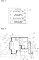
- Fig. 2 shows a hardware configuration of the controller 160.
- the controller 160 includes a central processing unit (CPU) 601, a communication interface 602, a read only memory (ROM) 603, a random access memory (RAM) 604, and a secondary storage device 605.
- the CPU 601, the communication interface 602, the ROM 603, the RAM 604, and the secondary storage device 605 are connected to each other via a bus 606.
- the CPU 601 centrally controls the controller 160. Functions implemented by the CPU 601 will be described later.
- the communication interface 602 includes a network interface card/controller (NIC) for wired or wireless communication.
- the communication interface 602 is communicably connected to the remote control 170, the heat pump unit 110, the bathtub circulation pump 145, the tank circulation pump 155, and the adding device 148.
- the controller 160 receives data of the user's operations on the remote control 170 through the communication interface 602 and sends control signals to each unit of the hot-water supply apparatus 100 through the communication interface 602.
- the ROM 603 stores plural pieces of firmware or data used in executing the pieces of firmware.
- the RAM 604 provides a working area for the CPU 601.
- the secondary storage device 605 may be a readable and writable nonvolatile semiconductor memory, such as electrically erasable programmable read-only memory (EEPROM) and flash memory, or a hard disk drive.
- the secondary storage device 605 stores programs for controlling operations of the hot-water supply apparatus 100 and data used in executing these programs.
- the data used in executing the programs include various parameters for controlling operation modes of the hot-water supply apparatus 100 and data indicating control of the bathtub circulation pump 145 and the tank circulation pump 155.
- Fig. 3 is a functional block diagram of the controller 160. As shown in Fig. 3 , in terms of functional units, the controller 160 includes a user interface unit 611, a device state acquisition unit 612, a device control unit 613, and an operation mode execution unit 614. These functional units are implemented by the CPU 601 executing one or more programs stored in the secondary storage device 605.
- the user interface unit 611 performs user interface processing through the remote control 170. In other words, the user interface unit 611 receives the user's operations on the remote control 170. The user interface unit 611 also sends information to be presented to the user (e.g., information indicating operating conditions of the hot-water supply apparatus 100) to the remote control 170, which in turn displays that information.
- information to be presented to the user e.g., information indicating operating conditions of the hot-water supply apparatus 100
- the device state acquisition unit 612 acquires data from the heat pump unit 110 including its operating conditions and measured temperatures and data from the bathtub circulation pump 145 and the tank circulation pump 155 indicating their driving conditions, at predetermined time intervals such as every 30 seconds.
- the device state acquisition unit 612 also acquires temperature of the hot water in the hot-water tank 120 from the hot water storage temperature sensors 121 and 122.
- the device control unit 613 controls operations of the hot-water supply apparatus 100 as a whole according to the user's operations on the remote control 170. Specifically, the device control unit 613 sends control signals to the heat pump unit 110 to control the compressor, the expansion valve, the fan, and other components. The device control unit 613 also sends control signals to the bathtub circulation pump 145, the tank circulation pump 155, and the adding device 148 during a heat recovery operation and a washing operation to control start and stop of the operations. The device control unit 613 also sends control signals to the three-way valve 151, the first four-way valve 152, and the second four-way valve 153 to switch the flow paths.
- the operation mode execution unit 614 causes the device control unit 613 to perform control corresponding to an operation mode selected by the user's operations on the remote control 170. Specifically, the operation mode execution unit 614 reads from the secondary storage device 605 programs and data for control of the heat pump unit 110 or the bathtub circulation pump 145 and the tank circulation pump 155 corresponding to a selected operation mode and causes the device control unit 613 to perform that control.
- the selected operation mode is, for example, a boiling operation, a heat recovery operation, or a bathtub washing operation.
- the heat recovery operation is an operation for the hot-water supply apparatus 100 to recover heat of the hot water in the bathtub 200.
- the washing operation is an operation to wash the bathtub 200.
- Fig. 4 shows hot water flow during the heat recovery operation.
- both of the bathtub circulation pump 145 and the tank circulation pump 155 are driven, so that hot water flows in both of the bathtub circulation passage 140 and the tank circulation passage 150.
- the flow of hot water in the bathtub 200 is as follows.
- the hot water discharged from the bathtub 200 passes through the bathtub return pipe 141 and has its pressure increased by the bathtub circulation pump 145 before entering the heat exchanger 130.
- the hot water then flows out of the heat exchanger 130 and passes through the bathtub supply pipe 142 to return to the bathtub 200.
- the flow of hot water in the hot-water tank 120 will be explained.
- the hot water discharged from the lower part of the hot-water tank 120 passes through the three-way valve 151 and has its pressure increased by the tank circulation pump 155. After having its pressure increased by the tank circulation pump 155, the hot water passes through the first four-way valve 152 and then the second four-way valve 153 and enters the heat exchanger 130. The hot water then flows out of the heat exchanger 130 and enters the hot-water tank 120 from a middle part thereof.
- the three-way valve 151, the first four-way valve 152, and the second four-way valve 153 are opened in a specific direction, they are assumed to be closed in the other directions.
- the three-way valve 151, the first four-way valve 152, and the second four-way valve 153 are switched so that the hot water flows through the hot-water tank 120, the three-way valve 151, the tank circulation pump 155, the first four-way valve 152, the second four-way valve 153, the heat exchanger 130, and the hot-water tank 120 in this order.
- heat exchanger 130 heat is exchanged between the hot water in the bathtub 200 and the hot water in the hot-water tank 120. This allows to recover the heat of the hot water in the bathtub 200 into the hot water in the hot-water tank 120 when temperature of the hot water in the bathtub 200 is higher than that of the hot water in the lower part of the hot-water tank 120.
- Fig. 5 shows hot water flow during the washing operation.
- the bathtub circulation pump 145 is driven, so that the hot water flows in the bathtub circulation passage 140.
- the hot water flowing out of the bathtub 200 passes through the bathtub return pipe 141 and has its pressure increased by the bathtub circulation pump 145 before entering the heat exchanger 130.
- the hot water then flows out of the heat exchanger 130 and passes through the bathtub supply pipe 142 to return to the bathtub 200. Circulating the hot water in this way generates a water current in the bathtub 200, whereby the bathtub 200 can be washed.
- the adding device 148 adds the additive to the hot water in the bathtub 200. This means that the hot water including the additive circulates in the bathtub 200, which can enhance the washing effect for the bathtub 200.
- the washing operation does not require heat exchange between the hot water in the bathtub 200 and the hot water in the hot-water tank 120, and thus the tank circulation pump 155 is not driven. Accordingly, the hot water in the hot-water tank 120 does not flow in the tank circulation passage 150.
- the hot-water supply apparatus 100 of the present embodiment can perform both of the heat recovery operation and the washing operation.
- the bathtub circulation pump 145 and the bathtub circulation passage 140 are used.
- the heat recovery operation and the washing operation can share the same configuration, which eliminates the need for individual circulation passages and circulation pumps for these operations.
- This allows to perform both of the heat recovery operation and the washing operation while avoiding increase in the number of parts of the hot-water supply apparatus 100 and in its size and also resultant increase in product costs.
- the heat recovery operation and the washing operation share the same configuration, no complicated control is required, which realizes efficient heat recovery and washing operations.
- the hot-water supply apparatus 100 of the present embodiment automatically controls the timing of performing the heat recovery operation and the washing operation for optimization of these operations.
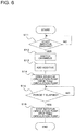
- Fig. 6 is a flowchart of the heat recovery operation and the washing operation in the present embodiment.
- the CPU 601 executes one or more programs stored in the secondary storage device 605.
- S11 start of the washing operation has been instructed
- the device control unit 613 switches channels of the three-way valve 151, the first four-way valve 152, and the second four-way valve 153 so that the hot water in the hot-water tank 120 flows in the tank circulation passage 150 (S12).
- the adding device 148 adds the additive to the hot water in the bathtub 200 in response to control signals from the device control unit 613 (S13).
- the device control unit 613 drives the bathtub circulation pump 145 and the tank circulation pump 155 (S14). This causes the hot water in the bathtub 200 to circulate in the bathtub circulation passage 140 and causes the hot water in the hot-water tank 120 to circulate in the tank circulation passage 150. At this time, heat exchange takes place in the heat exchanger 130 between the hot water in the bathtub 200 and the hot water in the hot-water tank 120. This results in the heat of the hot water in the bathtub 200 being recovered into the hot water in the hot-water tank 120, whereby the heat recovery operation is performed. Also, the hot water added with the additive circulates in the bathtub circulation passage 140 and the bathtub 200, whereby the washing operation is performed.
- the device control unit 613 After a lapse of a predetermined period T (S15: YES), the device control unit 613 stops the bathtub circulation pump 145 and the tank circulation pump 155 (S16), which finishes the heat recovery operation and the washing operation.
- the predetermined period T is preset and stored in the secondary storage device 605. Alternatively, the predetermined period T may be set by the user as desired or may be varied according to the device state acquired by the device state acquisition unit 612.
- the heat recovery operation and the washing operation are simultaneously performed in response to the operation of the single switch, namely the bathtub washing switch 171.
- This can not only simplify the operation but also shorten the operation time of the bathtub circulation pump 145, as compared to a case when the heat recovery operation and the washing operation are individually performed. As a result, this can optimize these operations and reduce power consumption.
- Adding the additive to the hot water in the bathtub 200 can reduce channel resistance of the bathtub circulation passage 140 due to the surface-activating effect of the additive. This can reduce input from the bathtub circulation pump 145 at a given equivalent circulation rate, as compared to a case when the heat recovery operation is performed alone. This can make the heat recovery operation more energy-efficient, as compared to a case when the heat recovery operation is performed alone.
- the bathtub circulation pump 145 and the tank circulation pump 155 may be stopped at other times than when the predetermined period T has elapsed.
- the bathtub circulation pump 145 and the tank circulation pump 155 may be stopped when the temperature of the hot water in the bathtub 200 falls to or below a predetermined temperature (e.g., 30 degrees C).
- the bathtub circulation pump 145 and the tank circulation pump 155 may be stopped when no difference is observed between the temperature of the hot water in the bathtub 200 and the temperature of the hot water stored in the lower part of the hot-water tank 120, which is detected by the hot water storage temperature sensor 122.
- the bathtub circulation pump 145 and the tank circulation pump 155 are not necessarily stopped simultaneously; one of the bathtub circulation pump 145 and the tank circulation pump 155 may be stopped earlier than the other.
- Embodiment 2 of the present invention will be described below.
- the present embodiment differs from Embodiment 1 in terms of when the heat recovery operation and the washing operation are performed.
- the configuration of the hot-water supply apparatus 100 and the hot water flow during the heat recovery operation and the bathtub washing operation are similar to those in Embodiment 1.
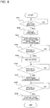
- Fig. 7 is a flowchart of the heat recovery operation and the washing operation in the present embodiment.
- the heat recovery operation is started after the washing operation has been started.
- S21 start of the washing operation has been instructed
- this determination is made based on whether the bathtub washing switch 171 of the remote control 170 has been operated.
- the device control unit 613 sends control signals to the adding device 148, which in turn adds the additive to the hot water in the bathtub 200 (S22).
- the device control unit 613 then drives the bathtub circulation pump 145 (S23). This causes the hot water including the additive to circulate in the bathtub circulation passage 140 and the bathtub 200, whereby the washing operation is performed.
- the washing operation is continued until a predetermined period T 1 elapses (S24: NO).
- the device control unit 613 switches channels of the three-way valve 151, the first four-way valve 152, and the second four-way valve 153 so that the hot water in the hot-water tank 120 flows in the tank circulation passage 150 (S25).
- the device control unit 613 then drives the tank circulation pump 155 (S26), causing the hot water in the hot-water tank 120 to circulate in the tank circulation passage 150.
- heat exchange takes place in the heat exchanger 130 between the hot water in the bathtub 200 and the hot water in the hot-water tank 120, whereby the heat recovery operation is performed.
- the washing operation and the heat recovery operation are continued until a predetermined period T 2 elapses (S27: NO). After a lapse of the predetermined period T 2 (S27: YES), the device control unit 613 stops the bathtub circulation pump 145 and the tank circulation pump 155 (S28), which finishes the heat recovery operation and the washing operation.
- the washing operation and the heat recovery operation are successively performed in response to operation of the single switch.
- higher temperature of the hot water in the bathtub 200 provides a higher washing effect.
- the temperature of the hot water in the bathtub 200 drops as a result of performing the heat recovery operation.
- performing the heat recovery operation after the start of the washing operation as in the present embodiment can keep the water temperature high during washing, and this can provide a high washing effect.
- the tank circulation pump 155 may be driven at other times than when the predetermine period T 1 has elapsed after driving of the bathtub circulation pump 145.
- the timing to drive the tank circulation pump 155 may be determined based on the temperature of the hot water stored in the hot-water tank 120 or the bathtub 200.
- the tank circulation pump 155 may be driven to start the heat recovery operation when the temperature of the hot water stored in the bathtub 200 falls to or below 35 degrees C or when temperature difference between the hot water stored in the bathtub 200 and the hot water stored in the lower part of the hot-water tank 120 falls within 5 degrees C. This ensures the minimum heat recovery amount in the heat recovery operation.
- the bathtub circulation pump 145 and the tank circulation pump 155 are not necessarily stopped simultaneously; one of the bathtub circulation pump 145 and the tank circulation pump 155 may be stopped earlier than the other.
- Embodiment 3 of the present invention will be described below.
- the present embodiment differs from Embodiment 1 in terms of when the heat recovery operation and the washing operation are performed.
- the configuration of the hot-water supply apparatus 100 and the hot water flow during the heat recovery operation and the bathtub washing operation are similar to those in Embodiment 1.
- Fig. 8 is a flowchart of the heat recovery operation and the washing operation in the present embodiment.
- the washing operation is performed after the heat recovery operation has been started.
- S31 start of the washing operation has been instructed
- this determination is made based on whether the bathtub washing switch 171 of the remote control 170 has been pressed. If start of the washing operation has been instructed (S31: YES), the device control unit 613 switches channels of the three-way valve 151, the first four-way valve 152, and the second four-way valve 153 so that the hot water in the hot-water tank 120 flows in the tank circulation passage 150 (S32).
- the device control unit 613 then drives the bathtub circulation pump 145 and the tank circulation pump 155 (S33). This causes the hot water in the bathtub 200 to circulate in the bathtub circulation passage 140 and causes the hot water in the hot-water tank 120 to circulate in the tank circulation passage 150. Thus, heat exchange takes place in the heat exchanger 130 between the hot water in the bathtub 200 and the hot water in the hot-water tank 120, whereby the heat recovery operation is performed.
- the heat recovery operation is continued until a predetermined period T 3 elapses (S34: NO).
- the device control unit 613 sends control signals to the adding device 148, which in turn adds the additive to the hot water in the bathtub 200 (S35).
- the hot water in the bathtub 200 has already been circulating in the bathtub circulation passage 140, and adding the additive to the hot water means start of the washing operation with a high washing effect.
- the heat recovery operation and the washing operation are successively performed in response to operation of the single switch.
- the additive added to the bathtub 200 may negatively affect heat transfer performance of the heat exchanger 130.
- performing the heat recovery operation with the additive added to the bathtub 200 may not produce a high heat recovery effect.
- performing the washing operation after the start of the heat recovery operation as in the present embodiment can prevent deterioration of the heat transfer performance of the heat exchanger 130 during heat recovery and produce a high energy-saving effect.
- the additive may be added at other times than when the predetermined period T 3 has elapsed after driving of the bathtub circulation pump 145 and the tank circulation pump 155.
- the timing to add the additive may be determined based on the temperature of the hot water stored in the hot-water tank 120 or the bathtub 200. Specifically, when the temperature of the hot water in the bathtub 200 falls to or below a predetermined temperature (e.g., 35 degrees C), the additive may be added to ensure washing effect. Alternatively, when temperature difference between the hot water stored in the bathtub 200 and the hot water stored in the lower part of the hot-water tank 120 falls within 2 degrees C, the additive may be added as no heat recovery effect will be expected from such temperature difference any more.
- a predetermined temperature e.g. 35 degrees C
- the tank circulation pump 155 After a lapse of the predetermined period T 4 from the addition of the additive to the bathtub 200, the tank circulation pump 155 is stopped.
- the timing to stop the tank circulation pump 155 may be determined based on the temperature of the hot water stored in the hot-water tank 120 or the bathtub 200 or power consumption of the tank circulation pump 155. For example, when temperature difference between the hot water stored in the bathtub 200 and the hot water stored in the lower part of the hot-water tank 120 falls within 2 degrees C, the tank circulation pump 155 may be stopped to terminate the heat recovery operation as no heat recovery effect will be expected from such temperature difference any more.
- the tank circulation pump 155 may be stopped to finish the heat recovery operation.
- the hot-water supply apparatus 100 of the above Embodiments 1 to 3 is a heat pump hot-water supply apparatus that uses the heat pump unit 110 as a heat source apparatus
- the hot-water supply apparatus 100 may use an electric heater or gas combustion as a heat source instead of the heat pump unit 110.
- Embodiments 1 to 3 a configuration is explained in which the washing operation and the heat recovery operation are simultaneously or successively performed since the controller judges that heat start of recovery operation is instructed due to pressing of the bathtub washing switch 171 of the remote control 170.
- the remote control 170 may include both of the bathtub washing switch 171 and a bathtub heat recovery switch (not shown), and in response to pressing of either button, the washing operation and the heat recovery operation may be simultaneously or successively performed.
- the bathtub washing switch 171 and the bathtub heat recovery switch are not limited to physical switches, and software key or voice instruction may also be used.
- the remote control 170 of the hot-water supply apparatus 100 is not essential, and the controller 160 may be capable of communicating with an external terminal other than the remote control 170.
- the instruction to start the washing operation may be sent from the external terminal. Further, the instruction to start the washing operation or the heat recovery operation is not limited to one given by the user, and may be automatically given by the operation mode execution unit 614 according to schedule information or other data stored in the secondary storage device 605.
- the adding device 148 of the hot-water supply apparatus 100 is also not essential to the present invention, and the user may put the additive into the bathtub 200.
- one exemplary method to clean the bathtub 200 using the hot-water supply apparatus 100 may be as follows: the user first adds the additive to the hot water in the bathtub 200, and then operates the bathtub washing switch 171 to simultaneously perform the heat recovery operation and the washing operation. Alternatively, the washing operation may be performed without the addition of the additive. Still alternatively, a device to generate bubbles for increased washing effect may replace the adding device 148. The device may generate bubbles in the hot water in the bathtub 200 in response to control signals from the controller 160, similarly to the adding device 148.
- hot-water supply apparatus 101 water supply end 102 hot water supply end 103 pressure reducing valve 110 heat pump unit 120 hot-water tank 121, 122 hot water storage temperature sensor 130 heat exchanger 140 bathtub circulation passage 141 bathtub return pipe 142 bathtub supply pipe 145 bathtub circulation pump 148 adding device 150 tank circulation passage 151 three-way valve 152 first four-way valve 153 second four-way valve 155 tank circulation pump 160 controller 170 remote control 171 bathtub washing switch 200 bathtub 601 CPU 602 communication interface 603 ROM 604 RAM 605 secondary storage device 606 bus 611 user interface unit 612 device state acquisition unit 613 device control unit 614 operation mode execution unit
Landscapes
- Engineering & Computer Science (AREA)
- Thermal Sciences (AREA)
- Chemical & Material Sciences (AREA)
- Combustion & Propulsion (AREA)
- Mechanical Engineering (AREA)
- General Engineering & Computer Science (AREA)
- Physics & Mathematics (AREA)
- Public Health (AREA)
- Health & Medical Sciences (AREA)
- Life Sciences & Earth Sciences (AREA)
- Hydrology & Water Resources (AREA)
- Water Supply & Treatment (AREA)
- Epidemiology (AREA)
- General Health & Medical Sciences (AREA)
- Heat-Pump Type And Storage Water Heaters (AREA)
- Control For Baths (AREA)
Abstract
Description
- The present invention relates to a hot-water supply apparatus supplying hot water to a bathtub.
- With recent advancement in functionality of hot water supply apparatuses, some of them now can not only generate hot water but also adjust temperature of supplied hot water to appropriate temperature and fill a bathtub with an appropriate amount of hot water. Another known hot-water supply apparatus can reheat hot water in a bathtub by delivering the hot water in the bathtub to the hot-water supply apparatus with a pump and make the hot water exchange heat with hot water generated by the hot-water supply apparatus.
- Patent Literature 1 discloses a hot-water supply apparatus that makes hot water in a bathtub exchange heat with hot water stored in a hot-water tank provided to the hot-water supply apparatus and thereby recovers heat of the hot water in the bathtub to achieve energy saving. Patent Literature 2 discloses a hot-water supply apparatus that washes a bathtub by heating hot water in the bathtub and generating microbubbles and circulating them in the bathtub.
-
- Patent Literature 1: Japanese Patent No.
5126432 - Patent Literature 2: Japanese Unexamined Patent Application Publication No.
2016-048130 - For increased energy efficiency and convenience, there has been an increasing demand for a hot-water supply apparatus that can perform both of heat recovery and bathtub washing. However, performing both of heat recovery and bathtub washing means increase in functions of the hot-water supply apparatus, which may lead to increase in the number of parts and device size and resultant increase in product costs.
- The present invention has been made in view of the above problems and aims to provide a hot-water supply apparatus that can perform both of heat recovery and bathtub washing without increase in product costs.
- According to one embodiment of the present invention, there is provided a hot-water supply apparatus including: a hot-water tank configured to store water; a heat exchanger configured to allow the water stored in the hot-water tank and water stored in a bathtub to exchange heat with each other; a bathtub circulation passage configured to allow the water stored in the bathtub to flow out of the bathtub and return to the bathtub via the heat exchanger; a bathtub circulation pump provided to the bathtub circulation passage and configured to circulate the water stored in the bathtub through the bathtub circulation passage; and a controller configured to perform a heat recovery operation in which heat of the water stored in the bathtub is recovered into the water stored in the hot-water tank, and a washing operation in which an inside of the bathtub is washed, wherein, in both the heat recovery operation and the washing operation, the bathtub circulation pump is activated to circulate the water stored in the bathtub through the bathtub circulation passage.
- In both of the heat recovery operation and the washing operation, the hot-water supply apparatus according to one embodiment of the present invention drives the bathtub circulation pump to make the hot water in the bathtub circulate in the bathtub circulation passage. This means that the same configuration is shared by the heat recovery operation and the washing operation. This allows to perform both of the heat recovery operation and the washing operation without increase in product costs due to increased parts and device size.
-
- [
Fig. 1] Fig. 1 is a schematic configuration diagram of a hot-water supply apparatus in Embodiment 1. - [
Fig. 2] Fig. 2 shows a hardware configuration of a controller. - [
Fig. 3] Fig. 3 is a functional block diagram of the controller. - [
Fig. 4] Fig. 4 shows hot water flow during a heat recovery operation. - [
Fig. 5] Fig. 5 shows hot water flow during a washing operation. - [
Fig. 6] Fig. 6 is a flowchart of the heat recovery operation and the washing operation in Embodiment 1. - [
Fig. 7] Fig. 7 is a flowchart of the heat recovery operation and the washing operation in Embodiment 2. - [
Fig. 8] Fig. 8 is a flowchart of the heat recovery operation and the washing operation in Embodiment 3. - Embodiments of the present invention will be described below with reference to the drawings. Throughout the figures as referred to in the present specification, same reference numerals refer to similar elements. In the present specification, the term "hot water" collectively refers to hot water and water.
-
Fig. 1 is a schematic configuration diagram of a hot-water supply apparatus 100 in Embodiment 1 of the present invention. The hot-water supply apparatus 100 of the present embodiment is configured to heat low-temperature water supplied from awater supply end 101 and supply hot water of a temperature desired by a user from a hotwater supply end 102. The hotwater supply end 102 is, for example, a water supply port of abathtub 200, a faucet or a shower head in a bathroom, or a faucet in a lavatory or a kitchen. - The hot-
water supply apparatus 100 includes aheat pump unit 110 for heating low-temperature water, a hot-water tank 120 for storing high-temperature water heated by theheat pump unit 110, and aheat exchanger 130 for exchanging heat between hot water in the hot-water tank 120 and hot water in thebathtub 200. The hot-water supply apparatus 100 further includes abathtub circulation passage 140 to allow the hot water to be discharged from thebathtub 200 to return to thebathtub 200 through theheat exchanger 130, and atank circulation passage 150 to allow the hot water discharged from the hot-water tank 120 to return to the hot-water tank 120 through theheat exchanger 130. The hot-water supply apparatus 100 further includes acontroller 160 controlling overall operations of the hot-water supply apparatus 100, and aremote control 170. The hot-water supply apparatus 100 further includes a boiling passage to allow the hot water in the hot-water tank 120 to circulate through theheat pump unit 110, a hot water supply passage to supply the hot water in the hot-water tank 120 to thebathtub 200, and three-way vales, on-off valves, and check valves installed in the above passages, though these components are not essential in the present invention. - For example, the
heat pump unit 110 is a refrigeration cycle device that uses CO2 or hydrofluorocarbon (HFC) as refrigerant. Theheat pump unit 110 includes a compressor, a first heat exchanger exchanging heat between the refrigerant and water, an expansion valve, a second heat exchanger exchanging heat between outside air and the refrigerant, a fan, a temperature sensor, and a control board. The compressor, the first heat exchanger, the expansion valve, and the second heat exchanger are circularly connected, forming a refrigeration cycle circuit (also called a refrigerant circuit) for circulation of the refrigerant. - The hot-
water tank 120 is a cylindrical tank made of metal, such as stainless steel, or resin. The outside of the hot-water tank 120 is covered with a heat insulator (not shown). This allows to keep the temperature of high-temperature water in the hot-water tank 120 over a long period. The hot-water tank 120 is connected at its lower part to thewater supply end 101 through a pipe provided with apressure reducing valve 103. Low-temperature water supplied from thewater supply end 101 has its pressure adjusted by thepressure reducing valve 103 to a predetermined pressure before flowing into the hot-water tank 120. Lower and upper parts of the hot-water tank 120 are connected to theheat pump unit 110 through the boiling passage. This allows low-temperature water discharged from the lower part of the hot-water tank 120 to undergo heat exchange in the first heat exchanger of theheat pump unit 110 to be high-temperature water and then return to the upper part of the hot-water tank 120. This circulation forms a boiling circuit. Also, inside the hot-water tank 120, there is temperature stratification where upper layers of hot water in the vertical direction has higher temperature and lower layers of hot water in the vertical direction has lower temperature. - Plural hot water
storage temperature sensors water tank 120 at different heights. The hot waterstorage temperature sensors water tank 120. Detection results of the hot waterstorage temperature sensors controller 160, which in turn figures out the amount of hot water stored in the hot-water tank 120 and uses that information for control of start and stop of a boiling operation (described later). The number of hot water storage temperature sensors is not limited to two and may be more than two. - The
heat exchanger 130 exchanges heat between the hot water in thebathtub 200 and the hot water in the hot-water tank 120. More specifically, theheat exchanger 130 is located on thebathtub circulation passage 140 and thetank circulation passage 150 and exchanges heat between the hot water flowing in thebathtub circulation passage 140 and the hot water flowing in thetank circulation passage 150. - The
bathtub circulation passage 140 includes pipes connecting the hot-water supply apparatus 100 and thebathtub 200. Thebathtub circulation passage 140 made up of abathtub return pipe 141 and abathtub supply pipe 142. On thebathtub circulation passage 140, there is abathtub circulation pump 145 to circulate the hot water in thebathtub 200. Driving thebathtub circulation pump 145 causes the hot water to circulate between the hot-water supply apparatus 100 and thebathtub 200. More specifically, driving thebathtub circulation pump 145 causes the hot water in thebathtub 200 to flow into the hot-water supply apparatus 100 through thebathtub return pipe 141 and then go from the hot-water supply apparatus 100 and return into thebathtub 200 through thebathtub supply pipe 142. - The
bathtub supply pipe 142 is provided with an addingdevice 148 to add an additive to the hot water in thebathtub 200 during a washing operation. In response to control signals from thecontroller 160, the addingdevice 148 adds the additive to the hot water in thebathtub 200. Examples of the additive include one having a surface-activating effect. Circulating the hot water including the additive in thebathtub 200 during a washing operation in this way can enhance the washing effect for thebathtub 200. - The
tank circulation passage 150 includes pipes connecting the upper and middle parts of the hot-water tank 120 through theheat exchanger 130. Thetank circulation passage 150 is provided with atank circulation pump 155 to deliver the hot water in the hot-water tank 120 to theheat exchanger 130. Thetank circulation passage 150 is also provided with a three-way valve 151, a first four-way valve 152, and a second four-way valve 153. Switching each of the three-way valve 151, the first four-way valve 152, and the second four-way valve 153 allows to switch the circulation passages for the hot water in the hot-water tank 120. - The
bathtub circulation pump 145 and thetank circulation pump 155 each include an inverter circuit (not shown) and are driven in response to control signals from thecontroller 160. Changing the rotation speed of thebathtub circulation pump 145 and thetank circulation pump 155 allows to change the amount of hot water flowing in thebathtub circulation passage 140 and thetank circulation passage 150. - The
controller 160 is communicably connected to each unit of the hot-water supply apparatus 100. In response to a user operating theremote control 170, thecontroller 160 controls each unit of the hot-water supply apparatus 100. Specifically, thecontroller 160 controls operations of theheat pump unit 110, thebathtub circulation pump 145, thetank circulation pump 155, and the addingdevice 148 and switching of the three-way valve 151, the first four-way valve 152, and the second four-way valve 153. Thecontroller 160 also causes theremote control 170 to display operating conditions of the hot-water supply apparatus 100 and a screen for operating the hot-water supply apparatus 100. Details of thecontroller 160 will be described later. - The
remote control 170 includes a display for displaying information such as operating conditions of the hot-water supply apparatus 100, and an operation part for receiving the user's operations on the hot-water supply apparatus 100. The operation part includes abathtub washing switch 171 to instruct start of a washing operation. Operations on theremote control 170 are transmitted to thecontroller 160. - Now a detailed description will be given on a configuration of the
controller 160 of the hot-water supply apparatus 100.Fig. 2 shows a hardware configuration of thecontroller 160. As shown inFig. 2 , thecontroller 160 includes a central processing unit (CPU) 601, acommunication interface 602, a read only memory (ROM) 603, a random access memory (RAM) 604, and asecondary storage device 605. TheCPU 601, thecommunication interface 602, theROM 603, theRAM 604, and thesecondary storage device 605 are connected to each other via abus 606. TheCPU 601 centrally controls thecontroller 160. Functions implemented by theCPU 601 will be described later. - The
communication interface 602 includes a network interface card/controller (NIC) for wired or wireless communication. Thecommunication interface 602 is communicably connected to theremote control 170, theheat pump unit 110, thebathtub circulation pump 145, thetank circulation pump 155, and the addingdevice 148. Thecontroller 160 receives data of the user's operations on theremote control 170 through thecommunication interface 602 and sends control signals to each unit of the hot-water supply apparatus 100 through thecommunication interface 602. - The
ROM 603 stores plural pieces of firmware or data used in executing the pieces of firmware. TheRAM 604 provides a working area for theCPU 601. - The
secondary storage device 605 may be a readable and writable nonvolatile semiconductor memory, such as electrically erasable programmable read-only memory (EEPROM) and flash memory, or a hard disk drive. Thesecondary storage device 605 stores programs for controlling operations of the hot-water supply apparatus 100 and data used in executing these programs. The data used in executing the programs include various parameters for controlling operation modes of the hot-water supply apparatus 100 and data indicating control of thebathtub circulation pump 145 and thetank circulation pump 155. -
Fig. 3 is a functional block diagram of thecontroller 160. As shown inFig. 3 , in terms of functional units, thecontroller 160 includes auser interface unit 611, a devicestate acquisition unit 612, adevice control unit 613, and an operationmode execution unit 614. These functional units are implemented by theCPU 601 executing one or more programs stored in thesecondary storage device 605. - The
user interface unit 611 performs user interface processing through theremote control 170. In other words, theuser interface unit 611 receives the user's operations on theremote control 170. Theuser interface unit 611 also sends information to be presented to the user (e.g., information indicating operating conditions of the hot-water supply apparatus 100) to theremote control 170, which in turn displays that information. - The device
state acquisition unit 612 acquires data from theheat pump unit 110 including its operating conditions and measured temperatures and data from thebathtub circulation pump 145 and thetank circulation pump 155 indicating their driving conditions, at predetermined time intervals such as every 30 seconds. The devicestate acquisition unit 612 also acquires temperature of the hot water in the hot-water tank 120 from the hot waterstorage temperature sensors - The
device control unit 613 controls operations of the hot-water supply apparatus 100 as a whole according to the user's operations on theremote control 170. Specifically, thedevice control unit 613 sends control signals to theheat pump unit 110 to control the compressor, the expansion valve, the fan, and other components. Thedevice control unit 613 also sends control signals to thebathtub circulation pump 145, thetank circulation pump 155, and the addingdevice 148 during a heat recovery operation and a washing operation to control start and stop of the operations. Thedevice control unit 613 also sends control signals to the three-way valve 151, the first four-way valve 152, and the second four-way valve 153 to switch the flow paths. - The operation
mode execution unit 614 causes thedevice control unit 613 to perform control corresponding to an operation mode selected by the user's operations on theremote control 170. Specifically, the operationmode execution unit 614 reads from thesecondary storage device 605 programs and data for control of theheat pump unit 110 or thebathtub circulation pump 145 and thetank circulation pump 155 corresponding to a selected operation mode and causes thedevice control unit 613 to perform that control. The selected operation mode is, for example, a boiling operation, a heat recovery operation, or a bathtub washing operation. - A description will now be given on a heat recovery operation and a washing operation of the hot-
water supply apparatus 100 of the present embodiment. The heat recovery operation is an operation for the hot-water supply apparatus 100 to recover heat of the hot water in thebathtub 200. The washing operation is an operation to wash thebathtub 200. - First, the heat recovery operation of the hot-
water supply apparatus 100 of the present embodiment will be described.Fig. 4 shows hot water flow during the heat recovery operation. In the heat recovery operation, both of thebathtub circulation pump 145 and thetank circulation pump 155 are driven, so that hot water flows in both of thebathtub circulation passage 140 and thetank circulation passage 150. The flow of hot water in thebathtub 200 is as follows. The hot water discharged from thebathtub 200 passes through thebathtub return pipe 141 and has its pressure increased by thebathtub circulation pump 145 before entering theheat exchanger 130. The hot water then flows out of theheat exchanger 130 and passes through thebathtub supply pipe 142 to return to thebathtub 200. - The flow of hot water in the hot-
water tank 120 will be explained. The hot water discharged from the lower part of the hot-water tank 120 passes through the three-way valve 151 and has its pressure increased by thetank circulation pump 155. After having its pressure increased by thetank circulation pump 155, the hot water passes through the first four-way valve 152 and then the second four-way valve 153 and enters theheat exchanger 130. The hot water then flows out of theheat exchanger 130 and enters the hot-water tank 120 from a middle part thereof. When the three-way valve 151, the first four-way valve 152, and the second four-way valve 153 are opened in a specific direction, they are assumed to be closed in the other directions. During the heat recovery operation, the three-way valve 151, the first four-way valve 152, and the second four-way valve 153 are switched so that the hot water flows through the hot-water tank 120, the three-way valve 151, thetank circulation pump 155, the first four-way valve 152, the second four-way valve 153, theheat exchanger 130, and the hot-water tank 120 in this order. - In the
heat exchanger 130, heat is exchanged between the hot water in thebathtub 200 and the hot water in the hot-water tank 120. This allows to recover the heat of the hot water in thebathtub 200 into the hot water in the hot-water tank 120 when temperature of the hot water in thebathtub 200 is higher than that of the hot water in the lower part of the hot-water tank 120. - Now, a description will be given on the washing operation of the hot-
water supply apparatus 100 of the present embodiment.Fig. 5 shows hot water flow during the washing operation. During the washing operation, thebathtub circulation pump 145 is driven, so that the hot water flows in thebathtub circulation passage 140. The hot water flowing out of thebathtub 200 passes through thebathtub return pipe 141 and has its pressure increased by thebathtub circulation pump 145 before entering theheat exchanger 130. The hot water then flows out of theheat exchanger 130 and passes through thebathtub supply pipe 142 to return to thebathtub 200. Circulating the hot water in this way generates a water current in thebathtub 200, whereby thebathtub 200 can be washed. During the washing operation, the addingdevice 148 adds the additive to the hot water in thebathtub 200. This means that the hot water including the additive circulates in thebathtub 200, which can enhance the washing effect for thebathtub 200. - The washing operation does not require heat exchange between the hot water in the
bathtub 200 and the hot water in the hot-water tank 120, and thus thetank circulation pump 155 is not driven. Accordingly, the hot water in the hot-water tank 120 does not flow in thetank circulation passage 150. - As described above, the hot-
water supply apparatus 100 of the present embodiment can perform both of the heat recovery operation and the washing operation. In both of these operations, thebathtub circulation pump 145 and thebathtub circulation passage 140 are used. This means that the heat recovery operation and the washing operation can share the same configuration, which eliminates the need for individual circulation passages and circulation pumps for these operations. This allows to perform both of the heat recovery operation and the washing operation while avoiding increase in the number of parts of the hot-water supply apparatus 100 and in its size and also resultant increase in product costs. As the heat recovery operation and the washing operation share the same configuration, no complicated control is required, which realizes efficient heat recovery and washing operations. - When the heat recovery operation and the washing operation share the same configuration as in the present embodiment, the heat recovery operation and the washing operation may interfere with each other depending on how the user uses the hot-
water supply apparatus 100. This may compromise optimal operations. In view of this, the hot-water supply apparatus 100 of the present embodiment automatically controls the timing of performing the heat recovery operation and the washing operation for optimization of these operations. -
Fig. 6 is a flowchart of the heat recovery operation and the washing operation in the present embodiment. To implement the flowchart ofFig. 6 , theCPU 601 executes one or more programs stored in thesecondary storage device 605. First, it is determined whether start of the washing operation has been instructed (S11). The determination is made based on whether thebathtub washing switch 171 of theremote control 170 has been operated. When start of the washing operation has been instructed (S11: YES), thedevice control unit 613 switches channels of the three-way valve 151, the first four-way valve 152, and the second four-way valve 153 so that the hot water in the hot-water tank 120 flows in the tank circulation passage 150 (S12). Then, the addingdevice 148 adds the additive to the hot water in thebathtub 200 in response to control signals from the device control unit 613 (S13). - The
device control unit 613 drives thebathtub circulation pump 145 and the tank circulation pump 155 (S14). This causes the hot water in thebathtub 200 to circulate in thebathtub circulation passage 140 and causes the hot water in the hot-water tank 120 to circulate in thetank circulation passage 150. At this time, heat exchange takes place in theheat exchanger 130 between the hot water in thebathtub 200 and the hot water in the hot-water tank 120. This results in the heat of the hot water in thebathtub 200 being recovered into the hot water in the hot-water tank 120, whereby the heat recovery operation is performed. Also, the hot water added with the additive circulates in thebathtub circulation passage 140 and thebathtub 200, whereby the washing operation is performed. - After a lapse of a predetermined period T (S15: YES), the
device control unit 613 stops thebathtub circulation pump 145 and the tank circulation pump 155 (S16), which finishes the heat recovery operation and the washing operation. The predetermined period T is preset and stored in thesecondary storage device 605. Alternatively, the predetermined period T may be set by the user as desired or may be varied according to the device state acquired by the devicestate acquisition unit 612. - As described above, in the present embodiment, the heat recovery operation and the washing operation are simultaneously performed in response to the operation of the single switch, namely the
bathtub washing switch 171. This can not only simplify the operation but also shorten the operation time of thebathtub circulation pump 145, as compared to a case when the heat recovery operation and the washing operation are individually performed. As a result, this can optimize these operations and reduce power consumption. - Adding the additive to the hot water in the
bathtub 200 can reduce channel resistance of thebathtub circulation passage 140 due to the surface-activating effect of the additive. This can reduce input from thebathtub circulation pump 145 at a given equivalent circulation rate, as compared to a case when the heat recovery operation is performed alone. This can make the heat recovery operation more energy-efficient, as compared to a case when the heat recovery operation is performed alone. - The
bathtub circulation pump 145 and thetank circulation pump 155 may be stopped at other times than when the predetermined period T has elapsed. For example, thebathtub circulation pump 145 and thetank circulation pump 155 may be stopped when the temperature of the hot water in thebathtub 200 falls to or below a predetermined temperature (e.g., 30 degrees C). Alternatively, thebathtub circulation pump 145 and thetank circulation pump 155 may be stopped when no difference is observed between the temperature of the hot water in thebathtub 200 and the temperature of the hot water stored in the lower part of the hot-water tank 120, which is detected by the hot waterstorage temperature sensor 122. Also, thebathtub circulation pump 145 and thetank circulation pump 155 are not necessarily stopped simultaneously; one of thebathtub circulation pump 145 and thetank circulation pump 155 may be stopped earlier than the other. - Embodiment 2 of the present invention will be described below. The present embodiment differs from Embodiment 1 in terms of when the heat recovery operation and the washing operation are performed. The configuration of the hot-
water supply apparatus 100 and the hot water flow during the heat recovery operation and the bathtub washing operation are similar to those in Embodiment 1. -
Fig. 7 is a flowchart of the heat recovery operation and the washing operation in the present embodiment. In the present embodiment, the heat recovery operation is started after the washing operation has been started. First, it is determined whether start of the washing operation has been instructed (S21). Similarly to Embodiment 1, this determination is made based on whether thebathtub washing switch 171 of theremote control 170 has been operated. When start of the washing operation has been instructed (S21: YES), thedevice control unit 613 sends control signals to the addingdevice 148, which in turn adds the additive to the hot water in the bathtub 200 (S22). Thedevice control unit 613 then drives the bathtub circulation pump 145 (S23). This causes the hot water including the additive to circulate in thebathtub circulation passage 140 and thebathtub 200, whereby the washing operation is performed. - The washing operation is continued until a predetermined period T1 elapses (S24: NO). After a lapse of the predetermine period T1 (S24: YES), the
device control unit 613 switches channels of the three-way valve 151, the first four-way valve 152, and the second four-way valve 153 so that the hot water in the hot-water tank 120 flows in the tank circulation passage 150 (S25). Thedevice control unit 613 then drives the tank circulation pump 155 (S26), causing the hot water in the hot-water tank 120 to circulate in thetank circulation passage 150. Thus, heat exchange takes place in theheat exchanger 130 between the hot water in thebathtub 200 and the hot water in the hot-water tank 120, whereby the heat recovery operation is performed. - The washing operation and the heat recovery operation are continued until a predetermined period T2 elapses (S27: NO). After a lapse of the predetermined period T2 (S27: YES), the
device control unit 613 stops thebathtub circulation pump 145 and the tank circulation pump 155 (S28), which finishes the heat recovery operation and the washing operation. - As described above, in the present embodiment, the washing operation and the heat recovery operation are successively performed in response to operation of the single switch. In the washing operation, higher temperature of the hot water in the
bathtub 200 provides a higher washing effect. The temperature of the hot water in thebathtub 200 drops as a result of performing the heat recovery operation. In view of these, performing the heat recovery operation after the start of the washing operation as in the present embodiment can keep the water temperature high during washing, and this can provide a high washing effect. - The
tank circulation pump 155 may be driven at other times than when the predetermine period T1 has elapsed after driving of thebathtub circulation pump 145. For example, the timing to drive thetank circulation pump 155 may be determined based on the temperature of the hot water stored in the hot-water tank 120 or thebathtub 200. Specifically, thetank circulation pump 155 may be driven to start the heat recovery operation when the temperature of the hot water stored in thebathtub 200 falls to or below 35 degrees C or when temperature difference between the hot water stored in thebathtub 200 and the hot water stored in the lower part of the hot-water tank 120 falls within 5 degrees C. This ensures the minimum heat recovery amount in the heat recovery operation. Also, thebathtub circulation pump 145 and thetank circulation pump 155 are not necessarily stopped simultaneously; one of thebathtub circulation pump 145 and thetank circulation pump 155 may be stopped earlier than the other. - Embodiment 3 of the present invention will be described below. The present embodiment differs from Embodiment 1 in terms of when the heat recovery operation and the washing operation are performed. The configuration of the hot-
water supply apparatus 100 and the hot water flow during the heat recovery operation and the bathtub washing operation are similar to those in Embodiment 1. -
Fig. 8 is a flowchart of the heat recovery operation and the washing operation in the present embodiment. In the present embodiment, the washing operation is performed after the heat recovery operation has been started. First, it is determined whether start of the washing operation has been instructed (S31). Similarly to Embodiment 1, this determination is made based on whether thebathtub washing switch 171 of theremote control 170 has been pressed. If start of the washing operation has been instructed (S31: YES), thedevice control unit 613 switches channels of the three-way valve 151, the first four-way valve 152, and the second four-way valve 153 so that the hot water in the hot-water tank 120 flows in the tank circulation passage 150 (S32). - The
device control unit 613 then drives thebathtub circulation pump 145 and the tank circulation pump 155 (S33). This causes the hot water in thebathtub 200 to circulate in thebathtub circulation passage 140 and causes the hot water in the hot-water tank 120 to circulate in thetank circulation passage 150. Thus, heat exchange takes place in theheat exchanger 130 between the hot water in thebathtub 200 and the hot water in the hot-water tank 120, whereby the heat recovery operation is performed. - The heat recovery operation is continued until a predetermined period T3 elapses (S34: NO). After a lapse of the predetermine period T3 (S34: YES), the
device control unit 613 sends control signals to the addingdevice 148, which in turn adds the additive to the hot water in the bathtub 200 (S35). At this time, the hot water in thebathtub 200 has already been circulating in thebathtub circulation passage 140, and adding the additive to the hot water means start of the washing operation with a high washing effect. - After a lapse of a predetermined period T4 (S36: YES), the
tank circulation pump 155 is stopped (S37) to finish the heat recovery operation. Further, after a lapse of a predetermined period T5 (S38: YES), thebathtub circulation pump 145 is stopped (S39) to finish the washing operation. - As described above, in the present embodiment, the heat recovery operation and the washing operation are successively performed in response to operation of the single switch. Depending on the kind, the additive added to the
bathtub 200 may negatively affect heat transfer performance of theheat exchanger 130. In that case, performing the heat recovery operation with the additive added to thebathtub 200 may not produce a high heat recovery effect. In view of this, performing the washing operation after the start of the heat recovery operation as in the present embodiment can prevent deterioration of the heat transfer performance of theheat exchanger 130 during heat recovery and produce a high energy-saving effect. - The additive may be added at other times than when the predetermined period T3 has elapsed after driving of the
bathtub circulation pump 145 and thetank circulation pump 155. For example, the timing to add the additive may be determined based on the temperature of the hot water stored in the hot-water tank 120 or thebathtub 200. Specifically, when the temperature of the hot water in thebathtub 200 falls to or below a predetermined temperature (e.g., 35 degrees C), the additive may be added to ensure washing effect. Alternatively, when temperature difference between the hot water stored in thebathtub 200 and the hot water stored in the lower part of the hot-water tank 120 falls within 2 degrees C, the additive may be added as no heat recovery effect will be expected from such temperature difference any more. - After a lapse of the predetermined period T4 from the addition of the additive to the
bathtub 200, thetank circulation pump 155 is stopped. However, this is not restrictive. For example, the timing to stop thetank circulation pump 155 may be determined based on the temperature of the hot water stored in the hot-water tank 120 or thebathtub 200 or power consumption of thetank circulation pump 155. For example, when temperature difference between the hot water stored in thebathtub 200 and the hot water stored in the lower part of the hot-water tank 120 falls within 2 degrees C, thetank circulation pump 155 may be stopped to terminate the heat recovery operation as no heat recovery effect will be expected from such temperature difference any more. Alternatively, when the amount of power saved by the heat recovery, whose amount can be derived from the temperature of the hot water stored in thebathtub 200 and the hot water stored in the lower part of the hot-water tank 120, is less than the power consumed by thetank circulation pump 155, thetank circulation pump 155 may be stopped to finish the heat recovery operation. - The present invention is not limited to the above embodiments and may be modified and applied in various ways within the scope of the present invention. For example, while the hot-
water supply apparatus 100 of the above Embodiments 1 to 3 is a heat pump hot-water supply apparatus that uses theheat pump unit 110 as a heat source apparatus, the hot-water supply apparatus 100 may use an electric heater or gas combustion as a heat source instead of theheat pump unit 110. - In Embodiments 1 to 3, a configuration is explained in which the washing operation and the heat recovery operation are simultaneously or successively performed since the controller judges that heat start of recovery operation is instructed due to pressing of the
bathtub washing switch 171 of theremote control 170. However, this is not restrictive. For example, theremote control 170 may include both of thebathtub washing switch 171 and a bathtub heat recovery switch (not shown), and in response to pressing of either button, the washing operation and the heat recovery operation may be simultaneously or successively performed. Also, thebathtub washing switch 171 and the bathtub heat recovery switch (not shown) are not limited to physical switches, and software key or voice instruction may also be used. Theremote control 170 of the hot-water supply apparatus 100 is not essential, and thecontroller 160 may be capable of communicating with an external terminal other than theremote control 170. The instruction to start the washing operation may be sent from the external terminal. Further, the instruction to start the washing operation or the heat recovery operation is not limited to one given by the user, and may be automatically given by the operationmode execution unit 614 according to schedule information or other data stored in thesecondary storage device 605. - The adding
device 148 of the hot-water supply apparatus 100 is also not essential to the present invention, and the user may put the additive into thebathtub 200. In this case, one exemplary method to clean thebathtub 200 using the hot-water supply apparatus 100 may be as follows: the user first adds the additive to the hot water in thebathtub 200, and then operates thebathtub washing switch 171 to simultaneously perform the heat recovery operation and the washing operation. Alternatively, the washing operation may be performed without the addition of the additive. Still alternatively, a device to generate bubbles for increased washing effect may replace the addingdevice 148. The device may generate bubbles in the hot water in thebathtub 200 in response to control signals from thecontroller 160, similarly to the addingdevice 148. - 100 hot-
water supply apparatus 101water supply end 102 hotwater supply end 103pressure reducing valve 110heat pump unit 120 hot-water tank storage temperature sensor 130heat exchanger 140bathtub circulation passage 141bathtub return pipe 142 bathtub supply pipe
145bathtub circulation pump 148 addingdevice 150tank circulation passage 151 three-way valve 152 first four-way valve 153 second four-way valve 155tank circulation pump 160controller 170remote control 171bathtub washing switch 200bathtub 601CPU 602communication interface 603ROM 604RAM 605secondary storage device 606bus 611user interface unit 612 devicestate acquisition unit 613device control unit 614 operation mode execution unit
Claims (12)
- A hot-water supply apparatus comprising:a hot-water tank configured to store water;a heat exchanger configured to allow the water stored in the hot-water tank and water stored in a bathtub to exchange heat with each other;a bathtub circulation passage configured to allow the water stored in the bathtub to flow out of the bathtub and return to the bathtub via the heat exchanger;a bathtub circulation pump provided to the bathtub circulation passage and configured to circulate the water stored in the bathtub through the bathtub circulation passage; anda controller configured to performa heat recovery operation in which heat of the water stored in the bathtub is recovered into the water stored in the hot-water tank, anda washing operation in which an inside of the bathtub is washed,in both the heat recovery operation and the washing operation, the bathtub circulation pump being activated to circulate the water stored in the bathtub through the bathtub circulation passage.
- The hot-water supply apparatus of claim 1, wherein the controller is configured to perform both of the heat recovery operation and the washing operation in response to operation of a single switch.
- The hot-water supply apparatus of claim 1 or 2, wherein the controller is configured to perform the heat recovery operation and the washing operation either simultaneously or successively.
- The hot-water supply apparatus of claim 3, wherein the controller is configured to perform the heat recovery operation successively after the washing operation.
- The hot-water supply apparatus of claim 4, wherein the controller is configured to start the heat recovery operation when a predetermined period elapses after start of the washing operation; temperature of the water in the bathtub falls to or below a predetermined temperature; or temperature difference between the water in the bathtub and the water stored in a lower part of the hot-water tank falls to or below a predetermined temperature.
- The hot-water supply apparatus of claim 3, wherein the controller is configured to perform the washing operation successively after the heat recovery operation.
- The hot-water supply apparatus of claim 6, wherein the controller is configured to start the washing operation when a predetermined period elapses after start of the heat recovery operation; temperature of the water in the bathtub falls to or below a predetermined temperature; or temperature difference between the water in the bathtub and the water stored in a lower part of the hot-water tank falls to or below a predetermined temperature.
- The hot-water supply apparatus of claim 7, further comprising:a tank circulation passage configured to allow the water discharged from the hot-water tank to return to the hot-water tank through the heat exchanger; anda tank circulation pump provided to the tank circulation passage and configured to circulate the water in the hot-water tank through the tank circulation passage, whereinthe controller is configured to stop the heat recovery operation when predetermined period elapses after start of the washing operation; temperature difference between the water in the bathtub and the water stored in the lower part of the hot-water tank falls to or below predetermined temperature; or an amount of power saved by heat recovery, which is derived from temperature of the water in the bathtub and temperature of the water stored in the lower part of the hot-water tank, is less than power consumed by the tank circulation pump.
- The hot-water supply apparatus of any one of claims 1 to 7, further comprising:a tank circulation passage configured to allow the water discharged from the hot-water tank to return to the hot-water tank through the heat exchanger; anda tank circulation pump provided to the tank circulation passage and configured to circulate the water in the hot-water tank through the tank circulation passage, whereinthe controller is configured to drive the tank circulation pump and the bathtub circulation pump in the heat recovery operation, andthe controller is configured to drive the bathtub circulation pump and not to drive the tank circulation pump in the washing operation.
- The hot-water supply apparatus of any one of claims 1 to 9, further comprising an adding device configured to add an additive for enhancing a washing effect in the washing operation into the water stored in the bathtub.
- The hot-water supply apparatus of claim 10, wherein the additive has a surface-activating effect.
- A method of washing a bathtub using the hot-water supply apparatus of claim 1, the method comprising:adding an additive for enhancing a washing effect into water stored in the bathtub; andsimultaneously performing both of the heat recovery operation and the washing operation.
Applications Claiming Priority (1)
| Application Number | Priority Date | Filing Date | Title |
|---|---|---|---|
| PCT/JP2017/029133 WO2019030900A1 (en) | 2017-08-10 | 2017-08-10 | Hot water supply device |
Publications (3)
| Publication Number | Publication Date |
|---|---|
| EP3667195A1 true EP3667195A1 (en) | 2020-06-17 |
| EP3667195A4 EP3667195A4 (en) | 2020-07-22 |
| EP3667195B1 EP3667195B1 (en) | 2022-09-21 |
Family
ID=65272016
Family Applications (1)
| Application Number | Title | Priority Date | Filing Date |
|---|---|---|---|
| EP17921093.5A Active EP3667195B1 (en) | 2017-08-10 | 2017-08-10 | Hot water supply device |
Country Status (3)
| Country | Link |
|---|---|
| EP (1) | EP3667195B1 (en) |
| JP (1) | JP6921203B2 (en) |
| WO (1) | WO2019030900A1 (en) |
Families Citing this family (2)
| Publication number | Priority date | Publication date | Assignee | Title |
|---|---|---|---|---|
| CN112815520B (en) * | 2021-02-04 | 2024-12-13 | 深圳安吉尔饮水产业集团有限公司 | Double water heating structure and double water heating method |
| CN113465014B (en) * | 2021-05-25 | 2022-11-29 | 东南大学 | Double-source water supply system for gradient utilization of bath wastewater heat energy and control method thereof |
Family Cites Families (13)
| Publication number | Priority date | Publication date | Assignee | Title |
|---|---|---|---|---|
| JPS5126432B2 (en) | 1972-03-22 | 1976-08-06 | ||
| JPH10314516A (en) * | 1997-05-21 | 1998-12-02 | Matsushita Electric Ind Co Ltd | Bath water purification system |
| JP3821926B2 (en) * | 1997-09-29 | 2006-09-13 | 東芝機器株式会社 | Method and apparatus for cleaning hot water supply apparatus |
| JP2003083613A (en) * | 2001-09-07 | 2003-03-19 | Toto Ltd | Bathtub water waste heat recovery system |
| JP2003269791A (en) * | 2002-03-18 | 2003-09-25 | Matsushita Electric Ind Co Ltd | Bath heat recovery water heater |
| JP2007003078A (en) * | 2005-06-23 | 2007-01-11 | Hitachi Engineering & Services Co Ltd | Exhaust heat recovering system and heat exchanger cleaning device |
| JP5312215B2 (en) * | 2009-06-12 | 2013-10-09 | 株式会社長府製作所 | Heat recovery system |
| JP2011002147A (en) * | 2009-06-18 | 2011-01-06 | Mitsubishi Electric Corp | Storage type water heater |
| JP5585513B2 (en) * | 2011-03-30 | 2014-09-10 | 株式会社デンソー | Hot water system |
| JP2013221706A (en) * | 2012-04-18 | 2013-10-28 | Mitsubishi Electric Corp | Storage water heater |
| JP2014001911A (en) * | 2012-06-20 | 2014-01-09 | Chofu Seisakusho Co Ltd | Method for heating hot water storage tank |
| JP6318981B2 (en) * | 2014-08-27 | 2018-05-09 | 三菱電機株式会社 | Water heater |
| JP6507954B2 (en) * | 2015-09-08 | 2019-05-08 | 株式会社デンソー | Water heater |
-
2017
- 2017-08-10 JP JP2019535542A patent/JP6921203B2/en not_active Expired - Fee Related
- 2017-08-10 WO PCT/JP2017/029133 patent/WO2019030900A1/en not_active Ceased
- 2017-08-10 EP EP17921093.5A patent/EP3667195B1/en active Active
Also Published As
| Publication number | Publication date |
|---|---|
| JP6921203B2 (en) | 2021-08-18 |
| WO2019030900A1 (en) | 2019-02-14 |
| EP3667195B1 (en) | 2022-09-21 |
| EP3667195A4 (en) | 2020-07-22 |
| JPWO2019030900A1 (en) | 2020-05-28 |
Similar Documents
| Publication | Publication Date | Title |
|---|---|---|
| EP3163176B1 (en) | Heating and hot water supply system | |
| KR101393121B1 (en) | Storage type hot water supply device | |
| CN102269484A (en) | Solar-assisted heat ground source air-conditioning hot water integrated machine | |
| EP3667195B1 (en) | Hot water supply device | |
| JP6160497B2 (en) | Hot water storage water heater | |
| CN110296490B (en) | Hot water unit with constant temperature hot water function and control method thereof | |
| JP3778106B2 (en) | Heat pump water heater | |
| JP2009236424A (en) | Heat pump hot water supply system | |
| JP5655695B2 (en) | Hot water storage water heater | |
| JP6628643B2 (en) | Hot water supply system | |
| JP6683171B2 (en) | Hot water storage system | |
| JP6687004B2 (en) | Hot water storage system | |
| JP5909637B2 (en) | Water heater | |
| JP5163822B1 (en) | Water heater | |
| JP2013181709A (en) | Water heater | |
| JP6288352B2 (en) | Hot water storage water heater | |
| JP6687005B2 (en) | Hot water storage system | |
| JP5927495B2 (en) | Water heater | |
| JP2013032892A (en) | Hot water supply apparatus | |
| JP2013036709A (en) | Water heating apparatus | |
| JP2020176805A (en) | Heat pump water heater | |
| JP5942087B2 (en) | Water heater | |
| JP6111409B2 (en) | Water heater | |
| JP5934907B2 (en) | Water heater | |
| JP2013032893A (en) | Hot water supply apparatus |
Legal Events
| Date | Code | Title | Description |
|---|---|---|---|
| STAA | Information on the status of an ep patent application or granted ep patent |
Free format text: STATUS: THE INTERNATIONAL PUBLICATION HAS BEEN MADE |
|
| PUAI | Public reference made under article 153(3) epc to a published international application that has entered the european phase |
Free format text: ORIGINAL CODE: 0009012 |
|
| STAA | Information on the status of an ep patent application or granted ep patent |
Free format text: STATUS: REQUEST FOR EXAMINATION WAS MADE |
|
| 17P | Request for examination filed |
Effective date: 20200129 |
|
| AK | Designated contracting states |
Kind code of ref document: A1 Designated state(s): AL AT BE BG CH CY CZ DE DK EE ES FI FR GB GR HR HU IE IS IT LI LT LU LV MC MK MT NL NO PL PT RO RS SE SI SK SM TR |
|
| AX | Request for extension of the european patent |
Extension state: BA ME |
|
| A4 | Supplementary search report drawn up and despatched |
Effective date: 20200622 |
|
| RIC1 | Information provided on ipc code assigned before grant |
Ipc: A47K 3/00 20060101ALI20200616BHEP Ipc: F24H 1/00 20060101AFI20200616BHEP Ipc: F24H 1/18 20060101ALI20200616BHEP Ipc: F24D 17/00 20060101ALI20200616BHEP Ipc: F24D 19/10 20060101ALI20200616BHEP Ipc: A47K 3/02 20060101ALI20200616BHEP Ipc: F24D 17/02 20060101ALI20200616BHEP |
|
| DAV | Request for validation of the european patent (deleted) | ||
| DAX | Request for extension of the european patent (deleted) | ||
| GRAP | Despatch of communication of intention to grant a patent |
Free format text: ORIGINAL CODE: EPIDOSNIGR1 |
|
| STAA | Information on the status of an ep patent application or granted ep patent |
Free format text: STATUS: GRANT OF PATENT IS INTENDED |
|
| INTG | Intention to grant announced |
Effective date: 20220414 |
|
| GRAS | Grant fee paid |
Free format text: ORIGINAL CODE: EPIDOSNIGR3 |
|
| GRAA | (expected) grant |
Free format text: ORIGINAL CODE: 0009210 |
|
| STAA | Information on the status of an ep patent application or granted ep patent |
Free format text: STATUS: THE PATENT HAS BEEN GRANTED |
|
| AK | Designated contracting states |
Kind code of ref document: B1 Designated state(s): AL AT BE BG CH CY CZ DE DK EE ES FI FR GB GR HR HU IE IS IT LI LT LU LV MC MK MT NL NO PL PT RO RS SE SI SK SM TR |
|
| REG | Reference to a national code |
Ref country code: GB Ref legal event code: FG4D |
|
| REG | Reference to a national code |
Ref country code: CH Ref legal event code: EP |
|
| REG | Reference to a national code |
Ref country code: IE Ref legal event code: FG4D |
|
| REG | Reference to a national code |
Ref country code: DE Ref legal event code: R096 Ref document number: 602017062063 Country of ref document: DE |
|
| REG | Reference to a national code |
Ref country code: AT Ref legal event code: REF Ref document number: 1520129 Country of ref document: AT Kind code of ref document: T Effective date: 20221015 |
|
| REG | Reference to a national code |
Ref country code: LT Ref legal event code: MG9D |
|
| REG | Reference to a national code |
Ref country code: NL Ref legal event code: MP Effective date: 20220921 |
|
| PG25 | Lapsed in a contracting state [announced via postgrant information from national office to epo] |
Ref country code: SE Free format text: LAPSE BECAUSE OF FAILURE TO SUBMIT A TRANSLATION OF THE DESCRIPTION OR TO PAY THE FEE WITHIN THE PRESCRIBED TIME-LIMIT Effective date: 20220921 Ref country code: RS Free format text: LAPSE BECAUSE OF FAILURE TO SUBMIT A TRANSLATION OF THE DESCRIPTION OR TO PAY THE FEE WITHIN THE PRESCRIBED TIME-LIMIT Effective date: 20220921 Ref country code: NO Free format text: LAPSE BECAUSE OF FAILURE TO SUBMIT A TRANSLATION OF THE DESCRIPTION OR TO PAY THE FEE WITHIN THE PRESCRIBED TIME-LIMIT Effective date: 20221221 Ref country code: LV Free format text: LAPSE BECAUSE OF FAILURE TO SUBMIT A TRANSLATION OF THE DESCRIPTION OR TO PAY THE FEE WITHIN THE PRESCRIBED TIME-LIMIT Effective date: 20220921 Ref country code: LT Free format text: LAPSE BECAUSE OF FAILURE TO SUBMIT A TRANSLATION OF THE DESCRIPTION OR TO PAY THE FEE WITHIN THE PRESCRIBED TIME-LIMIT Effective date: 20220921 Ref country code: FI Free format text: LAPSE BECAUSE OF FAILURE TO SUBMIT A TRANSLATION OF THE DESCRIPTION OR TO PAY THE FEE WITHIN THE PRESCRIBED TIME-LIMIT Effective date: 20220921 |
|
| REG | Reference to a national code |
Ref country code: AT Ref legal event code: MK05 Ref document number: 1520129 Country of ref document: AT Kind code of ref document: T Effective date: 20220921 |
|
| PG25 | Lapsed in a contracting state [announced via postgrant information from national office to epo] |
Ref country code: HR Free format text: LAPSE BECAUSE OF FAILURE TO SUBMIT A TRANSLATION OF THE DESCRIPTION OR TO PAY THE FEE WITHIN THE PRESCRIBED TIME-LIMIT Effective date: 20220921 Ref country code: GR Free format text: LAPSE BECAUSE OF FAILURE TO SUBMIT A TRANSLATION OF THE DESCRIPTION OR TO PAY THE FEE WITHIN THE PRESCRIBED TIME-LIMIT Effective date: 20221222 |
|
| PG25 | Lapsed in a contracting state [announced via postgrant information from national office to epo] |
Ref country code: SM Free format text: LAPSE BECAUSE OF FAILURE TO SUBMIT A TRANSLATION OF THE DESCRIPTION OR TO PAY THE FEE WITHIN THE PRESCRIBED TIME-LIMIT Effective date: 20220921 Ref country code: RO Free format text: LAPSE BECAUSE OF FAILURE TO SUBMIT A TRANSLATION OF THE DESCRIPTION OR TO PAY THE FEE WITHIN THE PRESCRIBED TIME-LIMIT Effective date: 20220921 Ref country code: PT Free format text: LAPSE BECAUSE OF FAILURE TO SUBMIT A TRANSLATION OF THE DESCRIPTION OR TO PAY THE FEE WITHIN THE PRESCRIBED TIME-LIMIT Effective date: 20230123 Ref country code: ES Free format text: LAPSE BECAUSE OF FAILURE TO SUBMIT A TRANSLATION OF THE DESCRIPTION OR TO PAY THE FEE WITHIN THE PRESCRIBED TIME-LIMIT Effective date: 20220921 Ref country code: CZ Free format text: LAPSE BECAUSE OF FAILURE TO SUBMIT A TRANSLATION OF THE DESCRIPTION OR TO PAY THE FEE WITHIN THE PRESCRIBED TIME-LIMIT Effective date: 20220921 Ref country code: AT Free format text: LAPSE BECAUSE OF FAILURE TO SUBMIT A TRANSLATION OF THE DESCRIPTION OR TO PAY THE FEE WITHIN THE PRESCRIBED TIME-LIMIT Effective date: 20220921 |
|
| PG25 | Lapsed in a contracting state [announced via postgrant information from national office to epo] |
Ref country code: SK Free format text: LAPSE BECAUSE OF FAILURE TO SUBMIT A TRANSLATION OF THE DESCRIPTION OR TO PAY THE FEE WITHIN THE PRESCRIBED TIME-LIMIT Effective date: 20220921 Ref country code: PL Free format text: LAPSE BECAUSE OF FAILURE TO SUBMIT A TRANSLATION OF THE DESCRIPTION OR TO PAY THE FEE WITHIN THE PRESCRIBED TIME-LIMIT Effective date: 20220921 Ref country code: IS Free format text: LAPSE BECAUSE OF FAILURE TO SUBMIT A TRANSLATION OF THE DESCRIPTION OR TO PAY THE FEE WITHIN THE PRESCRIBED TIME-LIMIT Effective date: 20230121 Ref country code: EE Free format text: LAPSE BECAUSE OF FAILURE TO SUBMIT A TRANSLATION OF THE DESCRIPTION OR TO PAY THE FEE WITHIN THE PRESCRIBED TIME-LIMIT Effective date: 20220921 |
|
| P01 | Opt-out of the competence of the unified patent court (upc) registered |
Effective date: 20230512 |
|
| REG | Reference to a national code |
Ref country code: DE Ref legal event code: R097 Ref document number: 602017062063 Country of ref document: DE |
|
| PG25 | Lapsed in a contracting state [announced via postgrant information from national office to epo] |
Ref country code: NL Free format text: LAPSE BECAUSE OF FAILURE TO SUBMIT A TRANSLATION OF THE DESCRIPTION OR TO PAY THE FEE WITHIN THE PRESCRIBED TIME-LIMIT Effective date: 20220921 Ref country code: AL Free format text: LAPSE BECAUSE OF FAILURE TO SUBMIT A TRANSLATION OF THE DESCRIPTION OR TO PAY THE FEE WITHIN THE PRESCRIBED TIME-LIMIT Effective date: 20220921 |
|
| PLBE | No opposition filed within time limit |
Free format text: ORIGINAL CODE: 0009261 |
|
| STAA | Information on the status of an ep patent application or granted ep patent |
Free format text: STATUS: NO OPPOSITION FILED WITHIN TIME LIMIT |
|
| PG25 | Lapsed in a contracting state [announced via postgrant information from national office to epo] |
Ref country code: DK Free format text: LAPSE BECAUSE OF FAILURE TO SUBMIT A TRANSLATION OF THE DESCRIPTION OR TO PAY THE FEE WITHIN THE PRESCRIBED TIME-LIMIT Effective date: 20220921 |
|
| 26N | No opposition filed |
Effective date: 20230622 |
|
| PG25 | Lapsed in a contracting state [announced via postgrant information from national office to epo] |
Ref country code: SI Free format text: LAPSE BECAUSE OF FAILURE TO SUBMIT A TRANSLATION OF THE DESCRIPTION OR TO PAY THE FEE WITHIN THE PRESCRIBED TIME-LIMIT Effective date: 20220921 |
|
| PGFP | Annual fee paid to national office [announced via postgrant information from national office to epo] |
Ref country code: GB Payment date: 20230629 Year of fee payment: 7 |
|
| PGFP | Annual fee paid to national office [announced via postgrant information from national office to epo] |
Ref country code: FR Payment date: 20230703 Year of fee payment: 7 |
|
| REG | Reference to a national code |
Ref country code: DE Ref legal event code: R119 Ref document number: 602017062063 Country of ref document: DE |
|
| PG25 | Lapsed in a contracting state [announced via postgrant information from national office to epo] |
Ref country code: MC Free format text: LAPSE BECAUSE OF FAILURE TO SUBMIT A TRANSLATION OF THE DESCRIPTION OR TO PAY THE FEE WITHIN THE PRESCRIBED TIME-LIMIT Effective date: 20220921 |
|
| REG | Reference to a national code |
Ref country code: CH Ref legal event code: PL |
|
| PG25 | Lapsed in a contracting state [announced via postgrant information from national office to epo] |
Ref country code: MC Free format text: LAPSE BECAUSE OF FAILURE TO SUBMIT A TRANSLATION OF THE DESCRIPTION OR TO PAY THE FEE WITHIN THE PRESCRIBED TIME-LIMIT Effective date: 20220921 |
|
| PG25 | Lapsed in a contracting state [announced via postgrant information from national office to epo] |
Ref country code: LU Free format text: LAPSE BECAUSE OF NON-PAYMENT OF DUE FEES Effective date: 20230810 |
|
| PG25 | Lapsed in a contracting state [announced via postgrant information from national office to epo] |
Ref country code: LU Free format text: LAPSE BECAUSE OF NON-PAYMENT OF DUE FEES Effective date: 20230810 Ref country code: CH Free format text: LAPSE BECAUSE OF NON-PAYMENT OF DUE FEES Effective date: 20230831 |
|
| REG | Reference to a national code |
Ref country code: BE Ref legal event code: MM Effective date: 20230831 |
|
| REG | Reference to a national code |
Ref country code: IE Ref legal event code: MM4A |
|
| PG25 | Lapsed in a contracting state [announced via postgrant information from national office to epo] |
Ref country code: IT Free format text: LAPSE BECAUSE OF FAILURE TO SUBMIT A TRANSLATION OF THE DESCRIPTION OR TO PAY THE FEE WITHIN THE PRESCRIBED TIME-LIMIT Effective date: 20220921 |
|
| PG25 | Lapsed in a contracting state [announced via postgrant information from national office to epo] |
Ref country code: IE Free format text: LAPSE BECAUSE OF NON-PAYMENT OF DUE FEES Effective date: 20230810 |
|
| PG25 | Lapsed in a contracting state [announced via postgrant information from national office to epo] |
Ref country code: IE Free format text: LAPSE BECAUSE OF NON-PAYMENT OF DUE FEES Effective date: 20230810 Ref country code: DE Free format text: LAPSE BECAUSE OF NON-PAYMENT OF DUE FEES Effective date: 20240301 |
|
| PG25 | Lapsed in a contracting state [announced via postgrant information from national office to epo] |
Ref country code: BE Free format text: LAPSE BECAUSE OF NON-PAYMENT OF DUE FEES Effective date: 20230831 |
|
| PG25 | Lapsed in a contracting state [announced via postgrant information from national office to epo] |
Ref country code: BG Free format text: LAPSE BECAUSE OF FAILURE TO SUBMIT A TRANSLATION OF THE DESCRIPTION OR TO PAY THE FEE WITHIN THE PRESCRIBED TIME-LIMIT Effective date: 20220921 |
|
| PG25 | Lapsed in a contracting state [announced via postgrant information from national office to epo] |
Ref country code: BG Free format text: LAPSE BECAUSE OF FAILURE TO SUBMIT A TRANSLATION OF THE DESCRIPTION OR TO PAY THE FEE WITHIN THE PRESCRIBED TIME-LIMIT Effective date: 20220921 |
|
| GBPC | Gb: european patent ceased through non-payment of renewal fee |
Effective date: 20240810 |
|
| PG25 | Lapsed in a contracting state [announced via postgrant information from national office to epo] |
Ref country code: GB Free format text: LAPSE BECAUSE OF NON-PAYMENT OF DUE FEES Effective date: 20240810 |
|
| PG25 | Lapsed in a contracting state [announced via postgrant information from national office to epo] |
Ref country code: FR Free format text: LAPSE BECAUSE OF NON-PAYMENT OF DUE FEES Effective date: 20240831 |
|
| PG25 | Lapsed in a contracting state [announced via postgrant information from national office to epo] |
Ref country code: CY Free format text: LAPSE BECAUSE OF FAILURE TO SUBMIT A TRANSLATION OF THE DESCRIPTION OR TO PAY THE FEE WITHIN THE PRESCRIBED TIME-LIMIT; INVALID AB INITIO Effective date: 20170810 |
|
| PG25 | Lapsed in a contracting state [announced via postgrant information from national office to epo] |
Ref country code: HU Free format text: LAPSE BECAUSE OF FAILURE TO SUBMIT A TRANSLATION OF THE DESCRIPTION OR TO PAY THE FEE WITHIN THE PRESCRIBED TIME-LIMIT; INVALID AB INITIO Effective date: 20170810 |
|
| PG25 | Lapsed in a contracting state [announced via postgrant information from national office to epo] |
Ref country code: TR Free format text: LAPSE BECAUSE OF FAILURE TO SUBMIT A TRANSLATION OF THE DESCRIPTION OR TO PAY THE FEE WITHIN THE PRESCRIBED TIME-LIMIT Effective date: 20220921 |