EP3667129A1 - Unité de verrouillage pourvu de pièce tubulaire - Google Patents
Unité de verrouillage pourvu de pièce tubulaire Download PDFInfo
- Publication number
- EP3667129A1 EP3667129A1 EP19216284.0A EP19216284A EP3667129A1 EP 3667129 A1 EP3667129 A1 EP 3667129A1 EP 19216284 A EP19216284 A EP 19216284A EP 3667129 A1 EP3667129 A1 EP 3667129A1
- Authority
- EP
- European Patent Office
- Prior art keywords
- piston
- locking unit
- housing
- piece
- pipe section
- Prior art date
- Legal status (The legal status is an assumption and is not a legal conclusion. Google has not performed a legal analysis and makes no representation as to the accuracy of the status listed.)
- Granted
Links
- 230000005540 biological transmission Effects 0.000 claims abstract description 6
- 238000007789 sealing Methods 0.000 claims description 19
- 230000003993 interaction Effects 0.000 claims description 5
- 239000000565 sealant Substances 0.000 claims description 4
- 238000004519 manufacturing process Methods 0.000 description 19
- 230000004323 axial length Effects 0.000 description 17
- 238000000034 method Methods 0.000 description 15
- 238000004804 winding Methods 0.000 description 13
- 238000013461 design Methods 0.000 description 12
- 239000002184 metal Substances 0.000 description 11
- 239000000463 material Substances 0.000 description 10
- 239000012530 fluid Substances 0.000 description 8
- 229910001315 Tool steel Inorganic materials 0.000 description 5
- 239000003566 sealing material Substances 0.000 description 5
- 238000010146 3D printing Methods 0.000 description 4
- 238000002347 injection Methods 0.000 description 4
- 239000007924 injection Substances 0.000 description 4
- 238000001746 injection moulding Methods 0.000 description 4
- 238000002844 melting Methods 0.000 description 4
- 230000008018 melting Effects 0.000 description 4
- 239000000843 powder Substances 0.000 description 4
- 230000008569 process Effects 0.000 description 4
- 238000000110 selective laser sintering Methods 0.000 description 4
- 230000000903 blocking effect Effects 0.000 description 3
- 238000010276 construction Methods 0.000 description 3
- 229920001296 polysiloxane Polymers 0.000 description 3
- 102000004315 Forkhead Transcription Factors Human genes 0.000 description 2
- 108090000852 Forkhead Transcription Factors Proteins 0.000 description 2
- 241001295925 Gegenes Species 0.000 description 2
- 239000000654 additive Substances 0.000 description 2
- 230000000996 additive effect Effects 0.000 description 2
- 230000000694 effects Effects 0.000 description 2
- 230000002349 favourable effect Effects 0.000 description 2
- 238000003754 machining Methods 0.000 description 2
- 239000000696 magnetic material Substances 0.000 description 2
- 230000035515 penetration Effects 0.000 description 2
- 238000005245 sintering Methods 0.000 description 2
- 239000007787 solid Substances 0.000 description 2
- 238000003860 storage Methods 0.000 description 2
- 241001136792 Alle Species 0.000 description 1
- 238000004026 adhesive bonding Methods 0.000 description 1
- 230000008901 benefit Effects 0.000 description 1
- 230000008859 change Effects 0.000 description 1
- 239000011248 coating agent Substances 0.000 description 1
- 238000000576 coating method Methods 0.000 description 1
- 238000004891 communication Methods 0.000 description 1
- 230000001419 dependent effect Effects 0.000 description 1
- 238000011161 development Methods 0.000 description 1
- 230000018109 developmental process Effects 0.000 description 1
- 238000001125 extrusion Methods 0.000 description 1
- 238000009472 formulation Methods 0.000 description 1
- 239000002655 kraft paper Substances 0.000 description 1
- 239000000203 mixture Substances 0.000 description 1
- 230000000284 resting effect Effects 0.000 description 1
- 238000005476 soldering Methods 0.000 description 1
- 239000000243 solution Substances 0.000 description 1
- 238000013022 venting Methods 0.000 description 1
- 238000003466 welding Methods 0.000 description 1
Images


Classifications
-
- F—MECHANICAL ENGINEERING; LIGHTING; HEATING; WEAPONS; BLASTING
- F16—ENGINEERING ELEMENTS AND UNITS; GENERAL MEASURES FOR PRODUCING AND MAINTAINING EFFECTIVE FUNCTIONING OF MACHINES OR INSTALLATIONS; THERMAL INSULATION IN GENERAL
- F16H—GEARING
- F16H63/00—Control outputs from the control unit to change-speed- or reversing-gearings for conveying rotary motion or to other devices than the final output mechanism
- F16H63/02—Final output mechanisms therefor; Actuating means for the final output mechanisms
- F16H63/30—Constructional features of the final output mechanisms
- F16H63/34—Locking or disabling mechanisms
- F16H63/3416—Parking lock mechanisms or brakes in the transmission
- F16H63/3483—Parking lock mechanisms or brakes in the transmission with hydraulic actuating means
-
- F—MECHANICAL ENGINEERING; LIGHTING; HEATING; WEAPONS; BLASTING
- F16—ENGINEERING ELEMENTS AND UNITS; GENERAL MEASURES FOR PRODUCING AND MAINTAINING EFFECTIVE FUNCTIONING OF MACHINES OR INSTALLATIONS; THERMAL INSULATION IN GENERAL
- F16H—GEARING
- F16H63/00—Control outputs from the control unit to change-speed- or reversing-gearings for conveying rotary motion or to other devices than the final output mechanism
- F16H63/02—Final output mechanisms therefor; Actuating means for the final output mechanisms
- F16H63/30—Constructional features of the final output mechanisms
- F16H63/34—Locking or disabling mechanisms
- F16H63/3416—Parking lock mechanisms or brakes in the transmission
- F16H63/3458—Parking lock mechanisms or brakes in the transmission with electric actuating means, e.g. shift by wire
- F16H63/3475—Parking lock mechanisms or brakes in the transmission with electric actuating means, e.g. shift by wire using solenoids
-
- F—MECHANICAL ENGINEERING; LIGHTING; HEATING; WEAPONS; BLASTING
- F16—ENGINEERING ELEMENTS AND UNITS; GENERAL MEASURES FOR PRODUCING AND MAINTAINING EFFECTIVE FUNCTIONING OF MACHINES OR INSTALLATIONS; THERMAL INSULATION IN GENERAL
- F16H—GEARING
- F16H63/00—Control outputs from the control unit to change-speed- or reversing-gearings for conveying rotary motion or to other devices than the final output mechanism
- F16H63/02—Final output mechanisms therefor; Actuating means for the final output mechanisms
- F16H63/30—Constructional features of the final output mechanisms
- F16H63/34—Locking or disabling mechanisms
- F16H63/3416—Parking lock mechanisms or brakes in the transmission
- F16H63/3425—Parking lock mechanisms or brakes in the transmission characterised by pawls or wheels
-
- F—MECHANICAL ENGINEERING; LIGHTING; HEATING; WEAPONS; BLASTING
- F16—ENGINEERING ELEMENTS AND UNITS; GENERAL MEASURES FOR PRODUCING AND MAINTAINING EFFECTIVE FUNCTIONING OF MACHINES OR INSTALLATIONS; THERMAL INSULATION IN GENERAL
- F16H—GEARING
- F16H63/00—Control outputs from the control unit to change-speed- or reversing-gearings for conveying rotary motion or to other devices than the final output mechanism
- F16H63/02—Final output mechanisms therefor; Actuating means for the final output mechanisms
- F16H63/30—Constructional features of the final output mechanisms
- F16H63/34—Locking or disabling mechanisms
- F16H63/3416—Parking lock mechanisms or brakes in the transmission
- F16H63/3441—Parking locks engaging axially
Definitions
- the invention relates to a locking unit, in particular for the parking lock of an automatic transmission, for locking the movement of a piston which can be moved by a drive, in particular to which pressure or hydraulic pressure can be applied, the locking unit having an electromagnet and at least one locking element and the locking element with the armature or the armature rod of the electromagnet cooperates and the piston has at least one latching receptacle and the piston can be fixed by the holding interaction of the latching element with the latching receptacle.
- a generic locking unit is for example from the international patent application WO 2013/131926 known to the applicant.
- the invention relates to a locking unit, in particular for the parking lock of an automatic transmission, for locking the movement of a piston which can be moved by a drive, in particular to which pressure or hydraulic pressure can be applied, the locking unit having an electromagnet and at least one locking element and the locking element with the armature or the armature rod of the electromagnet cooperates and the piston has at least one latching receptacle and the piston can be fixed by the holding interaction of the latching element with the latching receptacle.
- the locking unit has an inner tube piece which is designed as a guide for the piston.
- the inner tube piece can generally be considered part of the locking unit or part of the housing.
- the guidance on the pipe section results in particularly good guidance of the piston, so that it can be moved as smoothly as possible.
- a pressure line channel can in particular be formed on the outside of the pipe section.
- a medium under pressure can flow into this in order to actuate the piston.
- the medium can advantageously be directed to a position at which it is required to drive the piston.
- the piston is at least partially mounted or arranged in a housing.
- the housing is at least partially, preferably completely, made of plastic. This has proven to be advantageous, in particular because of the easy workability and the low weight. However, other materials are also possible.
- the pressure line channel is preferably at least partially radially, with respect to the longitudinal axis of the piston, delimited on the inside by the outside of the pipe section and on the outside by the inside wall of the housing.
- the pipe section can be connected to the housing or be part of the housing.
- the piston preferably lies against the pipe section. This allows a particularly advantageous guidance of the piston along the pipe section.
- the request can be made along a full scope.
- the piston slides along the pipe section.
- the piston rests on the pipe section in a fluid-tight manner.
- the piston can advantageously be actuated by pressure.
- the piston preferably has a sealant which seals the piston on the pipe section in a fluid-tight manner. This allows a particularly tight execution.
- the sealant can be, for example, a sealing ring or an O-ring.
- the sealing ring or the O-ring can in particular be provided in a circumferential shoulder of the piston.
- the sealing ring or the O-ring are preferably provided in a piston pressure piece of the piston.
- the inside of the tube piece preferably forms an inner wall of the housing against which the piston rests
- the pipe section is preferably straight and / or cylindrical in shape at least along a section on which the piston is guided. This allows an advantageous interaction with the piston.
- the piece of pipe is preferably made of metal or plastic. These materials have proven to be advantageous. However, the use of other materials is also possible.
- the piston is at least partially supported in a middle piece that is at least partially surrounded by the housing.
- the center piece can in particular be designed like a sleeve.
- the center piece preferably forms a bearing surface for the piston or a piston pressure piece of the piston on an inside.
- the piston can be advantageously stored.
- the center piece can in particular be designed as a turned part or sintered molded part, be produced in a formative process or be produced by means of 3D printing, metal powder injection molding, selective laser melting or selective laser sintering. Such methods have proven to be advantageous. However, other methods are also possible.
- the middle piece preferably has an axial length of 100% to 200% or of 130% to 170% of a stroke of the piston.
- the middle piece has an axial length of 30% to 40% of an axial length of the piston.
- the middle piece has an axial length of 13% to 20% of an axial length of the locking unit.
- the center piece preferably has a radial outside, which carries the housing. This allows a reliable connection between the housing and the center piece.
- the middle piece can in particular be connected to a magnet housing of the electromagnet. This allows a secure reference between the two components.
- the center piece On its side facing away from the electromagnet and / or towards the piston tube, the center piece can have a circumferential contact shoulder, to which an annular and / or cone-like connection area adjoins.
- connection area carries the pipe section. This enables the pipe section to be reliably attached.
- connection area in particular radially on the outside, a number of inter-segment spaces can be formed as notches. This allows fluid to pass through, for example.
- the segment gaps are preferred as a fluidic connection between the pressure line channel and a pressure space within the Pipe piece trained. This enables pressure to be conducted from the pressure line channel into the pressure chamber.
- Respective support segments can be formed between the segment gaps, which support the pipe section. This allows a secure connection to the pipe section.
- the connection area can in particular be designed as a crown ring.
- the piston is completely hollow on the inside along its axial extent. This can save weight.
- the piston has a cavity that extends axially through the entire piston.
- the cavity is preferably open at both axial ends.
- the cavity has a wall, continuously or in sections, which is thinner than a quarter of a diameter of the piston or thinner than a tenth of the diameter of the piston.
- the piston has a completely hollow piston tube along an axial section and a piston pressure piece connected to the piston tube along a further axial section.
- the piston tube and piston pressure piece can be optimized separately from one another according to their respective functions.
- the locking receptacles are preferably formed in the piston pressure piece.
- the piston pressure piece is preferably closer to the electromagnet and more solid than the piston tube.
- the piston tube can in particular be designed as a deep-drawn part, from tool steel or from metal. However, other designs are also possible.
- the piston tube has a wall thickness of 5% to 15% of the diameter of the piston tube.
- the piston tube preferably has a tube center piece with an outside taper, the taper of the piston tube cooperating with a shoulder formed in the housing in order to limit movement of the piston away from the electromagnet. This movement can be limited easily and reliably.
- a piston spring can be provided between the housing and the piston, which presses the piston in the direction of the electromagnet.
- the piston can be pretensioned into a rest position, which it assumes in particular in the absence of an active actuation, for example in the absence of a fluid under pressure, and in the absence of a blockage.
- the piston is mounted opposite to the electromagnet in a slide bearing of the housing. This enables the piston to be guided reliably.
- the pressure line channel can preferably be hydraulically connected from the outside via a connection through the housing. This enables the supply of pressurized fluid.
- the locking unit has a latching unit which carries the latching elements.
- the latching unit can in particular have a section facing the electromagnet or an armature space of the electromagnet and a section facing the piston, each of which is designed as a sleeve.
- the section of the latching unit facing the electromagnet partially receives the armature in at least one end position.
- An interior is preferably formed in the locking unit or in the portion of the locking unit facing the piston, which is open on the piston side.
- An outer space can be formed between the latching unit and the housing or between the latching unit and the center piece.
- the exterior and interior can in particular be fluidly connected via a compensation opening formed in the latching unit. This can allow pressure equalization.
- the outside space is vented through a channel which is formed in or on the center piece. This allows the outside space to be kept at ambient pressure. By means of the compensation opening already mentioned, the interior can also be kept at ambient pressure.
- the latching unit is preferably permanently or directly connected to the housing. This enables a constant positional relationship.
- a control element can be arranged in the latching unit, which is firmly connected to the anchor rod. This can serve in particular to actuate the locking elements.
- the control element is preferably at least partially movable within the section facing the piston.
- a number of radial bores for receiving the latching elements are formed in the latching unit. As a result, the locking elements can be reliably guided.
- the latching elements can in particular be spherical. However, other shapes are also possible.
- the control element can preferably be designed to press the latching elements radially outwards at least in one position. This allows them to have a blocking effect.
- the latching elements when they are pressed radially outward, come into engagement with one of the latching receptacles. This can block movement of the piston.
- the latching unit and the center piece can in particular be formed in one piece. This allows easy manufacture.
- the middle piece and the latching unit are formed in one piece, the middle piece in the axial direction, relative to the longitudinal axis of the piston, being shorter on the piston side than the latching unit and in particular the radial bores of the latching unit in the radial direction, based on the Longitudinal axis of the piston, not be covered by the center piece.
- the piston preferably has at least two latching receptacles spaced axially apart from one another. This enables the piston to be locked in at least two positions. However, the use of more than two locking shots is also possible.
- the piston can be locked in two different positions by means of the two snap-in receptacles.
- a locking option in more than two positions can accordingly be possible.
- the electromagnet can in particular have a magnetic core which is arranged at an axial end of the locking device.
- the anchor rod is preferably guided in a bore in the magnetic core. This enables the anchor rod to be guided reliably.
- the piston preferably has an axially end-side connection region which also projects from the housing when the piston is completely retracted. This enables easy connection of an external element to the piston.
- connection area can in particular be designed like a fork. This enables an advantageous fastening of typical external elements.
- connection area can also be designed as a stamped fork head.
- the piston or the piston pressure piece is at least partially arranged radially between the latching unit and the housing or is arranged between the latching unit and the middle piece.
- the electromagnet preferably has a winding for generating a magnetic field for moving the armature and / or the armature rod. This enables easy operation.
- the latching unit and the center piece can be produced or designed as a one-piece injection molded part or in an additive manufacturing process.
- a number of radial recesses, in particular bores, can thus also be formed for receiving the latching elements in the latching unit.
- Center piece and locking unit can in particular be formed in one piece.
- the center piece can be made shorter on the piston side in the axial direction, based on the longitudinal axis of the piston, than the latching unit.
- the radial bores of the latching unit are not covered by the center piece in the radial direction, based on the longitudinal axis of the piston. This allows the bores to be formed by tools such as drills, which can be guided past the center piece.
- the inner tube piece is connected to the housing in a fluid-tight manner.
- Such a fluid-tight design can advantageously prevent leakage between the pipe section and the housing. Such a leak could, for example, lead to the escape of pressurized fluid into a space in which it could prevent the piston from moving.
- the pipe section is received in a groove in the housing. This enables reliable recording.
- the groove of the housing can in particular be annular. This allows it to adapt advantageously to a cylindrical piece of pipe.
- a seal is arranged between the housing and the pipe section. A sealing effect can thus advantageously be achieved.
- the seal can in particular be arranged in the groove. It can be an O-ring or a sealing ring.
- the seal can also be a sealing material or a silicone sealing material. Such designs have proven to be advantageous.
- a number of bores are formed in the tube piece, into which engaging parts of the housing engage.
- An advantageous fastening and / or sealing can thereby be achieved.
- the engagement parts can in particular be integrally formed with the rest of the housing. They can be produced, for example, during the manufacture of the housing by overmolding the pipe section.
- the housing has an in particular ring-like projection which partially encompasses the tube piece.
- the piece of pipe can thus advantageously be held and also sealed.
- the projection can delimit the groove radially on the inside in particular.
- the pipe section is connected to the housing in a gas-tight and / or pressure-tight manner is. In this way, a tightness beyond the fluid tightness can be achieved.
- the housing can carry the pipe section. This allows an exact positional relationship between the pipe section and the housing.
- the invention further relates to a method for producing a locking unit according to the invention, wherein the pipe section is provided and the housing is encapsulated around the pipe section.
- the housing can be produced in a simple manner and connected to the pipe section.
- the locking unit all designs and variants described here can be used.
- a groove can be formed in the housing, into which the pipe section is subsequently introduced.
- a number of bores can be formed in the tube piece, a number of engagement parts being or being formed in the housing, each of which engages in a bore. This allows a reliable connection.
- the engaging parts can in particular be integrally formed with the rest of the housing.
- the inside of the piston is hollow.
- the piston according to the aforementioned prior art is a complex turned part that is produced in a manufacturing process comprising several different machining steps.
- An essential aspect of a hollow design focuses on the individual To produce components in simple manufacturing processes.
- the proposed piston can be provided as a deep-drawn part, in which the relatively complex contour of this piston is realized in one machining step.
- the mass of such a piston can be reduced at the same time, which overall reduces the mass of the locking unit proposed according to the invention, which on the one hand saves resources and on the other hand also allows the drives to be used to be smaller with the same dynamic properties, and thus also more cost-effective and lighter to realize.
- the piston is at least partially mounted in a housing which is at least partially made of plastic.
- the housing according to the aforementioned prior art is also an elaborate, cylinder-like, turned part made of metal with high precision on the inside.
- the housing can consist, for example, of plastic, the plastic being sprayed onto the construction, for example, or being provided as a finished injection-molded component in which the individual parts of the locking unit according to the invention are then installed.
- the proposal according to the invention includes both direct mounting of the piston on the plastic, in which case, for example, the inside of the plastic housing can have a corresponding wear-reducing sliding equipment, such as a sliding coating or the like, as well as indirect mounting of the piston in the housing made of plastic .
- a suitable one preferably made of metal existing guide sleeve or a guide tube may be provided, the inside of which cooperates with the outside of the piston.
- the plastic housing that can be realized as an injection molded part or as an injection molded part can be easier and therefore less expensive to manufacture than the templates from the prior art.
- the proposal is not only limited to the more economical production method, but in turn reduces the mass of the entire locking unit, since a lighter material is used for the housing.
- the piston is at least partially supported in a middle piece, at least partially surrounded by a housing.
- the housing can be a component separate from the center piece and, since it no longer primarily has the task of supporting the piston, for example, can then be optimized in other respects. Since the housing is relatively large in volume, it can then be made of a lighter material (e.g. plastic) than the material of the center piece, which takes on the storage tasks and thus preferably consists, for example, of appropriate metallic bearing material.
- a lighter material e.g. plastic
- the piston is divided into two and has a hollow, for example deep-drawn piston tube and a piston pressure piece, for example designed as a turned part.
- the piston in particular the piston tube, is designed like a fork at its outer end.
- the piston preferably the piston pressure piece, has two latching receptacles which are offset axially to one another.
- At least part of the piston preferably the entire piston, is designed as a deep-drawn part.
- the housing made of plastic comprises or encloses a sleeve or pipe piece.
- the outside of the pipe section delimits a pressure line channel.
- the sleeve or tube piece is placed or pressed onto a central piece.
- the inside of the sleeve or tube piece forms a bearing for the piston or the piston tube.
- a venting channel is provided on the center piece, preferably on the side facing the electromagnet.
- the piston spring is located inside or outside the middle part.
- the center piece is designed as a sintered molded part or is produced in a formative process, in particular by means of 3D printing, metal powder injection molding, selective laser melting or selective laser sintering.
- Sintering or formative manufacturing are cost-effective manufacturing processes that can also be used to produce workpieces of almost any shape in a single operation.
- the central part enables a radial alignment of the latching unit.
- the invention also includes the use of the locking unit in a parking lock of an automatic transmission.
- this is not the only application of the proposed locking unit. It can be used wherever the position of a component moving axially, that is to say parallel to its longitudinal extent, has to be locked.
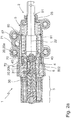
- the locking unit 1 according to the invention is shown schematically in a first embodiment.
- the locking unit 1 has a housing 5, at the front housing end 50 of which an opening 51 is provided, from which the front end 21 of the piston 2 protrudes.
- an electromagnet 3 connects to the housing 5 in the axial direction.
- Axial direction here means either the axis of symmetry or longitudinal axis 22 of the piston 2 or else the direction of movement of the piston 2.
- the piston 2 is movably mounted in the housing 5 in the axial direction, in particular along its longitudinal axis 22.
- a drive is provided for the movement of the piston 2, in particular the piston 2 can be acted upon with pressure, preferably with hydraulic pressure, the force component of this pressure being directed against the direction of force of a piston spring 23.
- the piston spring 23 is supported on the one hand on a housing shoulder or shoulder 53 of the housing 5 which adjoins the housing end 50 on the inside.
- the piston spring 23 is supported on a flange ring 24 of the piston 2. This flange ring 24 lies inside, centrally in the housing 5.
- the piston 2 moves due to the pressure between several positions, in the variant shown here, for example, two Positions provided.
- the position of the piston 2 in the respective positions can be determined by a latching unit 4, which is equipped with latching elements 40.
- the electromagnet 3 or its elements serve to actuate the latching unit 4, in particular for its latching elements 40.
- the electromagnet 3 has a coil body 32 which carries a winding 33. This has a wire through which electrical current can flow.
- the winding 33 is closed radially on the outside (with respect to the longitudinal axis 22) by a magnet housing 34. A magnetic field is created by energizing the winding 33.
- An armature space 35 is provided in the interior of the coil body 32, the armature space 35 in the present case filling approximately half of the interior of the coil body 32.
- the armature space 35 is oriented in the direction of the piston 2.
- the remaining area of the interior of the coil body 32 is filled by a magnetic core 36, which, as usual, consists of soft magnetic material that guides the magnetic field lines well.
- an armature 30 which in the exemplary embodiment shown here is cylindrical and has a bottom surface 37.
- An air gap 39 is formed between the bottom surface 37 and an end surface 38 of the magnetic core 36 facing the armature space 35.
- a magnetic spring 300 pushes the armature 30 to the right, so that the air gap 39 has its maximum expansion. If the winding 33 is energized, it generates a magnetic field which presses the armature 30 to the left against the force of the magnetic spring 300, so that the air gap 39 is closed.
- the anchor 30 carries an anchor rod 31.
- the anchor rod 31 is oriented concentrically to the anchor 30, anchor 30 and anchor rod 31 are movably mounted in the armature space 35 in the axial direction, ie parallel to the longitudinal axis 22.
- the construction is selected so that the armature 30 has an axial bore 301 which receives the armature rod 31.
- the anchor rod 31 protrudes from the anchor 30 on both sides thereof.
- An axial bore 302 is also provided in the magnetic core 36.
- the arrangement is chosen such that there is a bearing for the anchor rod 31 in this axial bore 302.
- the armature space 35 is delimited on one side by the magnetic core 36, the magnetic core 36, as already described, filling the part of the interior of the coil body 32 facing away from the piston 2 and thus also the axial end of the electromagnet 3, but also the locking unit 1 , together with the magnet housing 34, describes.
- the armature space 35 is delimited by a yoke part 41 which is pot-shaped and is preferably made of soft magnetic material in order to guide the magnetic field lines well. A part of the armature 30 is immersed in the cup-shaped yoke part 41.
- the yoke part 41 is part of the locking unit 4.
- the yoke part 41 has a penetration hole 47 which receives the anchor rod 31 and, if necessary, also supports it.
- the locking unit 4 is, seen in section, essentially H-shaped.
- the radially oriented web of the H forms the yoke part 41.
- This is followed by a first axial section 48 and a second axial section 49.
- the two axial sections 48, 49 of the H adjoining on both sides of the web are of different sizes or lengths, the section 49 facing the armature space 35 being significantly shorter axially than the section 48 facing the piston 2.
- the larger section 48 there In the present case or in typical designs, about 2 to 3, 3.5 or 4 times larger or longer than the smaller section 49.
- a radially extending (based on the longitudinal axis 22) compensation opening 405 is arranged in the foot region of the sleeve-like first axial section 48 facing the yoke part 41.
- This compensating opening 405 fluidly connects an inner space 42 to an outer space 406, in which a piston pressure piece 26 of the piston 2 moves axially. Pressure equalization between the inner space 42 and the outer space 406 is possible through the equalizing opening 405.
- the two sections 48, 49 each radially close off a corresponding receiving space.
- the smaller second section 49 delimits the armature space 35 (this is the pot-like yoke part 41) and the larger section 48 the interior 42.
- the interior 42 extends in the axial direction.
- the magnetic spring 300 is also provided, which is supported on the one hand on the upper side of the yoke part 41 facing the second section 49 and on the other hand on a control element 43 which is arranged at the end on the anchor rod 31.
- the control element 43 is arranged in a fixed position on the anchor rod 31.
- the control element 43 also has a receiving bore 401 into which the anchor rod 31 is inserted.
- the control element 43 is pressed in a suitable manner with the anchor rod 31 and is thus held in an exact position on it.
- the control element 43 essentially consists of two different geometrical bodies, a cylinder section and a cone section, the cone section forming a cone surface 400 on its outer surface.
- a lateral surface 403 of the cylinder section of the control element 43 is guided on an inner wall 402 which radially delimits the inner space 42, if appropriate also stored.
- At the axial end of the control element 43 facing the electromagnet 3 there is an annular recess 404 in which the end of the magnetic spring 300 protrudes and is thus reliably guided and held.
- the conical surface 400 is located at the end of the control element 43 opposite the recess 404.
- control element 43 It is clear that other constructions are also possible for the configuration of the control element 43. It is also conceivable, for example, that the conical surface on the control element is arranged on the side facing the electromagnet 3 and then the functioning of the locking unit 1 is changed if necessary.
- the control element urges the detent elements 40, which are designed as balls, radially outward and thus blocks the piston 2. The movement of the piston 2 can also be blocked when the electromagnet 3 is energized.
- the position of the air gap 39 is also variable according to the proposal.
- the embodiment shown is the air gap 39 on the side of the armature 30 facing away from the latching unit 4, that is to say between the armature 30 and the magnetic core 36.
- the air gap it is also possible for the air gap to then be between the armature 30 and the yoke part 41, that is to say the one Detent unit 4 facing side of the armature 30 is formed.
- the arrangement of the magnetic spring 300 in the interior 42 is advantageous since these elements do not impair the magnetic circuit that is formed in the elements around the armature space 35.
- an arrangement of the magnetic spring in the armature space or also outside of the locking unit 4 is possible in order to form a corresponding energy store.
- the air gap 39 closes by displacing the armature 30 to the left, as a result of which the armature rod 31 and the control element 43 carried by the armature rod 31 are also displaced to the left, as a result of which the magnetic spring 300 is compressed and thus an energy store for a return movement of the armature 30 - armature rod 31 - control element 43 forms when switching off the energization of the winding 33.
- the larger first section 48 of the latching unit 4 carries, at its end or end region 44 facing away from the yoke part 41, the latching element or elements 40, which in the present case are designed as balls.
- the larger section 48 (at least in the end region 44) is formed like a sleeve or cylinder.
- the locking elements 40 are provided as balls 40 in a ball cage.
- the sleeve-like or cylinder-like end region 44 of the section 48 has radially (with respect to the longitudinal axis 22) oriented bores 45 for receiving the latching elements 40 or balls.
- the detent elements 40 or balls 40 may or may not deflect radially inwards.
- the piston 2 consists of two individual parts.
- the piston 2 comprises a piston tube 25 which partially protrudes from the opening 51, and a piston pressure piece 26 which is produced separately therefrom.
- the arrangement is chosen such that the piston pressure piece 26 in the housing 5 connects to the inner end of the piston tube 25.
- the piston tube 25 is completely hollow on the inside. This is preferably formed as a deep-drawn part, for example made of metal such as tool steel or the like, as a result of which the manufacture of such an element is considerably cheaper.
- the wall thickness of the piston tube 25 in the present case is therefore only about 5 to about 15 percent of the diameter of the piston tube 25, or of the outside diameter of individual parts (e.g. inner end 27, first tube center piece 29, second tube center piece 202 and connection area 203) of the piston tube 25.
- the piston tube 25 bears against the piston pressure piece 26 with its flange ring 24 provided at the end.
- the flange ring 24 thus forms a radially oriented (with respect to the longitudinal axis 22) boundary surface of the piston tube 25.
- This inner end 27, which also includes the flange ring 24, is pushed onto the connecting ring 28, which closes off the piston pressure piece 26 in the direction of the piston tube 25 .
- a relatively precise fit can be provided here, and for example the piston tube 25 can be pressed onto the piston pressure piece 26 in this way.
- other connection methods such as welding, soldering or gluing the elements of the piston tube 25 and piston pressure piece 26 are alternatively possible.
- the end 27 then merges into a first tube center piece 29 in a taper 200, ie the diameter of the piston tube 25 in the area of the first tube center piece 29 is smaller than in the area of the end 27.
- the first tube center piece 29 then closes with another one designed as a shoulder second taper 201 to the second pipe center piece 202.
- the diameter of the piston tube 25 in the area of the second tube center piece 202 is smaller than in the area of the first tube center piece 29.
- This second taper 201 forms a stop.
- the piston 2 is guided in a slide bearing 54. This has an inner flange 55. If the piston 2 is shifted to the right, the movement is limited in that the shoulder-like taper 201 rests on the radially acting inner flange 55 of the slide bearing 54. Such a state is, for example, in Fig. 2b shown.
- the slide bearing 54 On the inside of the opening 51 of the housing 5, the slide bearing 54 just mentioned is provided for the piston tube 25.
- the second pipe center piece 202 is mounted on this slide bearing 54.
- the plain bearing 54 has an inner flange 55 oriented into the housing interior, which also forms the shoulder 53 in this area. Since the housing 5 is preferably made of plastic, this part is overmolded accordingly. However, it is also possible for the slide bearing 54 to be inserted into a separately produced, for example injection-molded, housing 5, for example a plastic housing. A relatively high accuracy is preferably advantageous here, that is to say in the region of the opening 51 and the embedding of the sliding bearing 54 in the housing 5.
- the piston 2 In the position of the locking unit 1 shown here, the piston 2 is fully inserted into the housing 5 and only the end-side connection region 203 of the piston 2 protrudes from the housing 5. Further elements, not shown here, which are moved or held by the piston 2, are connected to the piston 2 in the connecting region 203.
- the second pipe center piece 202 merges into the connecting area 203 in the third taper 204.
- all axial sections that is to say the inner end 27, the first taper 200, the first pipe center piece 29, the second pipe taper 201, the second pipe center piece 202, the third taper 204 and the connecting region 203 are hollow on the inside.
- connection area 203 has a recess provided on the central plane, that is to say it is slotted.
- a fork-like structure of the connection area 203 is formed, the remaining half-shells 211 of the connection area 203 nevertheless providing sufficient stability for the connection to a further element (not shown further).
- a bore or other penetration opening 210 is provided in the half-shell 211 for receiving a fastening bolt or the like.
- the piston pressure piece 26 is also essentially sleeve-like, that is to say hollow on the inside. Its outer surface 205 serves as a guide. At the front end facing the piston tube 25, an outer ring 206 is provided on the piston pressure piece 26. Its outer surface is mounted on an inner wall 56 of the housing, or at least guided. The outer ring 206 bears in the axial direction (based on the longitudinal axis 22) on the flange ring 24 of the piston tube 25. A pressure side 207 of the outer ring 206 facing away from the flange ring 24 is pressurized, preferably with hydraulic pressure, and is therefore also correspondingly solid. An annular pressure chamber 70 is provided here.
- the piston pressure piece 26 is therefore preferably realized as a turned part. It is preferably made of tool steel.
- a circumferential shoulder 208 is provided radially on the outside on the pressure side 207, which receives a 0-ring seal or a sealing ring 209. Since this 0-ring seal or the sealing ring 209 is exposed to the hydraulic pressure, it is also pressed in the radial direction and thus reliably closes a gap that may still remain between the radial outer surface of the outer ring 206 and the housing inner wall 56.
- a center piece 6 is also provided.
- the middle piece 6 is also sleeve-shaped and forms a bearing surface 60 for the piston pressure piece 26 on its inside.
- the bearing surface 60 acts together with the outer surface 205 of the piston pressure piece 26.
- the middle piece 6 is fixed in the locking unit 1.
- the center piece 6 is provided as a turned part and preferably consists of a common tool steel.
- the center piece 6 is designed as a sintered molded part or is produced in a formative process, in particular by means of 3D printing, metal powder injection molding, selective laser melting or selective laser sintering. Sintering or formative manufacturing are cost-effective manufacturing processes that can also be used to produce workpieces of almost any shape in a single operation.
- the center piece 6 has an axial length (in relation to the longitudinal axis 26).
- the axial length of the center piece 6 corresponds to approximately 100-200%, preferably approximately 130-170%, of the stroke of the piston 2.
- the axial length of the middle piece 6 corresponds to approximately 20-50%, preferably approximately 30-40%, of the axial length of the piston 2.
- the axial length of the middle piece 6 corresponds to approximately 10-30%, preferably approximately 13-20%, of the axial length of the locking unit 1.
- the outer surface 205 is the outer surface of a cylinder.
- the outer surface 205 bears on its side facing away from the piston tube 25
- the end facing the electromagnet 3 has a further O-ring seal 213 in a circumferential groove 212. This O-ring seal 213 seals the gap between the outer surface 205 and the bearing surface 60, which is under pressure, in the direction of the electromagnet 3.
- Piston 2 shown consists of the two components, the piston tube 25 and the piston pressure piece 26, which are mechanically firmly connected to one another in the variant shown here, for example because they are attached or pressed. Alternatively, they can also be designed so that they are flying towards one another, that is to say only because of the force effect of the pressure applied on the one hand and the force of the piston spring 23 directed against it on the other hand.
- This piston 2 which consists of two components, is initially supported by the piston pressure piece 26 on the bearing surface 60 of the center piece 6.
- Another bearing is alternatively provided on the outer ring 206 of the piston pressure piece 26 in cooperation with the inner wall 56 of the housing.
- the second tube center piece 202 of the piston tube 25 is mounted on the plain bearing 54 provided on one side.
- An inner surface 214 of the piston pressure piece 26 is also not smooth, but rather has bulges or latching receptacles 20, 20a, 20b that are axially spaced from one another (with respect to the longitudinal axis 22).
- the diameter of the ring-like bulges or snap-in receptacles 20, 20a, 20b is larger than the diameter of the inner surface 214 lying between them.
- the locking receptacles 20, 20a, 20b are screwed into the inner surface 214 of the sleeve-like piston pressure piece 26 as a shoulder or an internal shoulder.
- the latching unit 4 is arranged in a stationary manner in the housing 5, the piston 2 is axially or executed longitudinally. In the in Figure 1a shown position, however, the movement of the piston 2 to the right, in the direction of the opening 51, is blocked by the latching unit 4, the locking unit 1 is blocked in the retracted position of the piston 2.
- the latching unit 4 has latching elements 40, each of which is movably mounted radially (with respect to the longitudinal axis 22) in bores 45, for example balls 40 of a ball cage.
- the electromagnet 3 is shown in a dropped position, that is, the winding 33 is not supplied with current. Therefore, the air gap 39 is formed between the armature 30 and the magnetic core 36, since the magnetic spring 300 displaces the armature 30 to the right and thus also the control element 43, on which the magnetic fields 300 are supported.
- the control element 43 arrives at the axial position of the locking elements / balls 40 such that the conical surface 400 of the control element 43 acts on the locking elements / balls 40 and these radially (with respect to the longitudinal axis 22) to the outside, into the respective locking receptacles 20, 20a pushes. Then, however, a longitudinal movement of the piston 2, that is to say a movement of the piston 2 to the right, is blocked, since a first inner shoulder 215a, which delimits the latching receptacle 20, 20a, bears against the latching elements 40 which are offset radially outward.
- the first inner shoulder 215a is located on the first latching seat 20a on the side facing the second latching seat 20b.
- the second inner shoulder 215b is located on the side of the second latching seat 20b facing the first latching seat 20a.
- the two latching receptacles 20a and 20b are axially spaced apart (with respect to the longitudinal axis 22).
- the piston 2, in particular the piston pressure piece 26, is movably supported between the radially inside latching unit 4 and the radially outside center piece 6.
- the middle piece 6 takes a central position in the locking unit 1.
- it carries the sleeve-like housing 5 on its radial outer side 62.
- it also establishes a connection with the electromagnet 3, in particular with its magnet housing 34.
- a radially extending gap 65 can be seen in the lower region between the magnet housing 34 and the housing 5, which extends radially on the inside into a channel 66a which is in fluidic contact with an intermediate space 66b which results between the pressure piece 26 and the latching unit 4 .
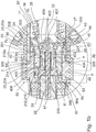
- the radially extending channel 66a is realized so that on one Electromagnet 3 facing foot area 68 (see 3a and 3b ) of the middle piece 6, a recess 67 (see 3a and 3b ) is provided and so the foot region 68 of the center piece 6 facing the electromagnet 3 does not abut the entire circumference of the flange part of the coil body 32.
- the fluidically connected elements intermediate space 66b, channel 66a and gap 65 allow the interior of the locking unit 1 to be vented.
- center piece 6 radially aligns the electromagnet 3 with the latching unit 4. In this area, it is advantageous to achieve a high concentricity.
- the center piece 6 has, on its side facing away from the electromagnet 3 or facing the piston tube 25, a circumferential contact shoulder 63, to which an annular and / or cone-like connection area 64 then adjoins.
- This connection area 64 is part of the center piece 6.
- the proposal according to the invention is very variable for the design of the connection area 64.
- the connection area 64 has several tasks.
- the pipe section 57 is pushed or pressed onto the preferably ring-like area of the connecting area 64.
- the piston 2, in particular the piston pressure piece 26 bears against the inner wall 56 of the housing, in this respect the pipe piece 57 has the properties of a cylinder. This preferably limits or guides Pipe piece 57 not only the pressure on its housing inner wall 56, but also on its pipe outside 58th
- the mounting of the first end piece of the tube piece 57 on the middle piece 6 underlines the central importance of the middle piece 6 in the embodiment shown here.
- the second end piece of the pipe section 57 is mounted in the housing 5 and the inside of the pipe section 57 serves as a bearing or guide for the piston 2.
- the pipe section 57 is connected to the housing 5 in a fluid-tight manner on the right-hand side. This is achieved in that the pipe section 57 is inserted into a groove 80 in the housing 5.
- the groove 80 is annular and is delimited radially on the inside by a projection 81 of the housing 5.
- the fluid-tight connection ensures that fluid under pressure, which is located in the pressure line channel 71, does not reach a region radially outside of the piston tube 25 at the connection point between the housing 5 and the pipe section 57, which causes a movement of the piston 2 to the right, which would just be achieved by the pressurized fluid as described below, would counteract.
- Possible versions of a tight connection are in the Figures 4a to 4c are shown and are described below.
- Pressure connection On the housing 5 is a, in Figure 1a Pressure connection, not shown, which provides a medium under pressure as a drive for the piston 2.
- This pressure connection is preferably arranged in the half of the housing 5 facing the opening 51, in particular it is located close, in particular very close to the opening 51.
- the pressure side 207 of the piston pressure piece which can be pressurized must be provided 26 in the retracted position of the piston 2 as far as possible from the opening 51.
- This boundary condition means that in the housing 5, or in the locking unit 1, the medium under pressure is initially opposite to the preferred direction of movement (the working movement realized by the pressurization) Figure 1a must be directed to the right) of the piston 2 in order to then be deflected at a suitable point and guided to the pressure side 207.
- the pressure connection is therefore in fluid communication with the pressure line channel 71, which runs essentially axially (with respect to the longitudinal axis 22).
- This pressure line channel 71 is radially inside from the outside 58 of the pipe section 57 and radially outside from the plastic housing 5, in particular the inside wall 500 thereof limited.
- the pressure line channel 71 can encompass the entire pipe section 57 (in relation to its circumferential direction) or only in one segment, as in FIG Figure 1a shown to extend axially.
- the pipe section 57 Since, according to one embodiment, the pipe section 57 is fixed, and therefore also tight or pressure-tight, it is plugged onto the connection area 64 of the center piece 6, an opening 501 is provided in the pipe section 57 at the axial height, based on the longitudinal axis 22, of the connection area 64 which the pressurized medium passes from the pressure line channel 71 into the pressure chamber 70 on the inside of the pipe section 57.
- the pipe section 57 thus has a plurality of tasks.
- Its inner wall 56 serves as a guide or bearing for the piston 2. Its outer side 58 serves at least partially as a pressure line channel 71.
- the pipe section 57 supports or stiffens the housing 5, which is preferably made of plastic.
- This combined design of the housing 5 combines low mass and inexpensive manufacture with high wear resistance and therefore with high availability of a locking unit equipped in this way.
- the tube piece 57 is surrounded at its end 59 facing away from the connection region 64 in a ring-like manner by the plastic material of the housing 5. Therefore, the pressure line channel 71 does not necessarily extend over the entire axial length of the pipe section 57.
- the pipe section 57 can be encapsulated by the plastic of the housing 5, alternatively, for example, the pipe section 57 can be inserted or pressed into a housing 5 produced in a separate manufacturing step become.
- the center piece 6 is formed like a sleeve. It has a foot region 68 facing the electromagnet 3 in the installed state, to which a central section 69 adjoins. On the side facing away from the foot area 68, the middle piece 6 is closed off by a connecting area 64.
- the middle section 69 has the largest diameter and, in the installed state, lies directly against the plastic material of the housing 5.
- the diameter of the foot region 68 is smaller than the diameter of the middle section 69.
- the foot region 68 is not completely designed as a circumferential ring, but rather has a recess 67 in a certain angular segment, which forms the channel 66a in the installed state.
- the central section 69 merges with the radially extending contact shoulder 63 into the connection area 64.
- the outer diameter of the connecting area 64 is also smaller than the diameter of the central section 69.
- the pipe section 57 is plugged onto the connecting area 64 in the installed state.
- a plurality of support segments 600 are provided in the connection area 64, which are formed as jacket segments on the cylindrical outer surface of the connection area 64 and are each separated by segment gaps 72.
- These segment gaps 72 are formed as recesses in the lateral surface of the connection area 64 and carry the medium, so the corresponding operating pressure prevails in the segment gaps 72 when installed and in operation.
- the segment gaps 72 are therefore part of the medium-carrying system.
- the embodiment of the center piece 6 after Figure 1a or 1b differs as follows: As already stated, there is a fluidic connection between the pressure line channel 71, which is arranged on the radial outside of the pipe section 57, and the pressure chamber 70, which is arranged on the radial inside of the pipe section 57. In the in the Figures 1a and 1b Example shown, this connection is realized through the opening 501 in the pipe section 57. The end 502 of the pipe section 57 facing the center piece 6 is completely pushed onto the connection area 64 and lies snugly (and thus also sealingly) against the radially outward-extending contact shoulder 63.
- the Figures 2a and 2 B show the use of the center piece 6 according to the Figures 3a and 3b . It can be clearly seen that the end 502 facing the center piece 6 is axially spaced (with respect to the longitudinal axis 22) from the contact shoulder 63. The in axial The segment gaps 72 extending in the direction (with respect to the longitudinal axis 22) are thus fluidly connected to the pressure line channel 71 and also the pressure chamber 70.
- the axial distance (based on the longitudinal axis 22) of the pipe end 502 to the contact shoulder 63 corresponds here to the opening 501, and here forms a radial connection from the inside of the pipe section 57 to the outside of the pipe section 57. This connection runs outside the pipe section 57, that is to say axially offset to the end of the pipe section 502.
- FIG. 2a and 2 B a second embodiment of the locking unit 1 according to the invention is shown in two different positions of the piston each in a vertical section.
- the blocking position of the latching unit 4 is realized in the dropped, ie not energized state of the electromagnet 3, but without defining the invention thereon, the blocking position can alternatively also be realized in the energized state of the electromagnet.
- FIGS. 4a to 4c each show a section of the connection point between the pipe section 57 and the housing 5, different possibilities of fastening and sealing being described.
- the pipe section 57 is received in a groove 80 which is annular and is delimited radially on the inside by a projection 81.
- a seal 82 in the form of a sealing ring is arranged between the housing 5 and the pipe section 57. This ensures a fluid-tight design.
- a seal 83 in the form of sealing material made of silicone is arranged to the side of the pipe section 57, which ensures the fluid-tight design. A holding of the pipe section 57 in the groove 80 can also be achieved.
- a number of bores 84 are formed in the pipe section, through which an engagement part 85 of the housing 5 passes. This can be done, for example, by injecting the housing 5 around the pipe section 57 during manufacture.
- the engagement part 85 can thus be connected to the rest of the housing 5 in a material-locking manner and thus ensure an advantageous fastening of the blank 57.
- end of the pipe section 57 can also be extrusion-coated without the arrangement of bores 84.
- the plastic material of the housing 5 can, for example, at least at the end of the pipe section 57 rest against the inside (through the projection 81) and outside.
- the invention includes: A locking unit, in particular for the parking lock of an automatic transmission, for locking the movement of a piston (2) which can be moved by a drive and in particular can be acted upon by pressure or hydraulic pressure, the locking unit (1) comprising an electromagnet (3) and at least one latching element ( 40) and the locking element (40) interacts with the armature (30) or the armature rod (31) of the electromagnet (3) and the piston (2) has at least one locking receptacle (20, 20a, 20b) and the piston (2) can be fixed by the holding interaction of the locking element (40) with the locking receptacle (20, 20a, 20b), the locking unit (1) having an inner tube piece (57) which is designed as a guide for the piston (2).
- sealing means is a sealing ring (209) or an O-ring.
- the above-mentioned locking unit, the pipe section (57) being straight and / or cylindrical in shape at least along a section on which the piston (2) is guided.
- the above-mentioned locking unit, the middle piece (6) being designed like a sleeve.
- the above-mentioned locking unit wherein the middle piece (6) is designed as a turned part or sintered molded part, is produced in a formative process or is produced by means of 3D printing, metal powder injection molding, selective laser melting or selective laser sintering.
- the above-mentioned locking unit the middle piece (6) having a radial outside (62) which supports the housing (5).
- the above-mentioned locking unit a number of segment gaps (72) being formed as notches in the connecting region (64) radially on the outside.
- segment spaces (72) are designed as a fluidic connection between the pressure line channel (71) and a pressure space (70) within the pipe section (57).
- connection area (64) being designed as a crown ring.
- the above-mentioned locking unit wherein the cavity has a wall, continuously or in sections, which is thinner than a quarter of a diameter of the piston (2) or thinner than a tenth of the diameter of the piston (2).
- the above-mentioned locking unit wherein the piston (2) has a completely hollow piston tube (25) along an axial section and a piston pressure piece (26) connected to the piston tube (25) along another axial section.
- the above-mentioned locking unit, the piston tube (25) being designed as a deep-drawn part, from tool steel or from metal.
- the above-mentioned locking unit the piston tube (25) having a tube center piece (29) with an outside taper (201), the taper (201) of the piston tube (25) interacting with a shoulder (53) formed in the housing (5), to limit movement of the piston (2) away from the electromagnet (3).
- the above-mentioned locking unit having a locking unit (4) which carries the locking elements (40).
- the above-mentioned locking unit, the latching unit (4) having a section (49) facing the electromagnet (3) or an armature space (35) of the electromagnet (3) and a section (48) facing the piston (2), each of which is sleeve-shaped are executed.
- the above-mentioned locking unit, the outer space (406) and the inner space (42) being fluidly connected via a compensation opening (405) formed in the latching unit (4).
- control element (43) is at least partially movable within the section (48) facing the piston (2).
- the above-mentioned locking unit, the latching elements (40) being spherical.
- control element (43) is designed to press the latching elements (40) radially outwards at least in one position.
- the above-mentioned locking unit, the latching unit (4) and the center piece (6) being formed in one piece.
- the above-mentioned locking unit wherein the piston (2) has at least two locking receptacles (20a, 20b) which are axially spaced apart.
- connection area (203) is designed like a fork.
- connection area (203) is designed as a stamped fork head.
- the above-mentioned locking unit having a winding (31) for generating a magnetic field for moving the armature (30) and / or the armature rod (31).
- the above-mentioned locking unit wherein the locking unit (4) and the center piece (6) are produced as a one-piece injection molded part or in one piece in an additive manufacturing process, by means of which a number of radial recesses, in particular bores (45), for receiving the locking elements (40 ) is formed in the locking unit (4).
- seal (82) is an O-ring or sealing ring.
- the aforementioned locking unit, wherein the seal (83) is a sealing material or a silicone sealing material.
- the above-mentioned locking unit the housing (5) having an in particular ring-like projection (81) which partially encompasses the pipe section (57).
Applications Claiming Priority (2)
| Application Number | Priority Date | Filing Date | Title |
|---|---|---|---|
| DE102018132354 | 2018-12-14 | ||
| DE102019114450.7A DE102019114450A1 (de) | 2018-12-14 | 2019-05-29 | Verriegelungseinheit mit Rohrstück |
Publications (2)
| Publication Number | Publication Date |
|---|---|
| EP3667129A1 true EP3667129A1 (fr) | 2020-06-17 |
| EP3667129B1 EP3667129B1 (fr) | 2024-03-27 |
Family
ID=68917433
Family Applications (1)
| Application Number | Title | Priority Date | Filing Date |
|---|---|---|---|
| EP19216284.0A Active EP3667129B1 (fr) | 2018-12-14 | 2019-12-13 | Unité de verrouillage pourvu de pièce tubulaire |
Country Status (1)
| Country | Link |
|---|---|
| EP (1) | EP3667129B1 (fr) |
Cited By (1)
| Publication number | Priority date | Publication date | Assignee | Title |
|---|---|---|---|---|
| EP3734122A1 (fr) * | 2019-04-30 | 2020-11-04 | SVM Schultz Verwaltungs-GmbH & Co. KG | Unité de verrouillage et procédé |
Citations (6)
| Publication number | Priority date | Publication date | Assignee | Title |
|---|---|---|---|---|
| KR100994104B1 (ko) * | 2010-08-02 | 2010-11-12 | 주식회사 유니크 | 자동변속기용 파킹 로크 장치 |
| EP2458226A1 (fr) * | 2010-11-29 | 2012-05-30 | Magnetbau Schramme GmbH & Co. KG | Dispositif de verrouillage |
| WO2013131926A1 (fr) | 2012-03-05 | 2013-09-12 | Svm Schultz Verwaltungs-Gmbh & Co. Kg | Unité de verrouillage, en particulier pour un frein de stationnement d'une boîte de vitesses automatique |
| US20150159752A1 (en) * | 2012-06-22 | 2015-06-11 | Zf Friedrichshafen Ag | Device for actuating a locking mechanism |
| US20160244031A1 (en) * | 2013-12-24 | 2016-08-25 | Aisin Aw Co., Ltd. | Parking device |
| US20180224022A1 (en) * | 2017-02-03 | 2018-08-09 | Svm Schultz Verwaltungs-Gmbh & Co. Kg | Valve, in particular a slide valve |
Family Cites Families (2)
| Publication number | Priority date | Publication date | Assignee | Title |
|---|---|---|---|---|
| DE10351907B4 (de) * | 2002-11-12 | 2016-09-22 | Schaeffler Technologies AG & Co. KG | Hydraulisches System |
| WO2018095477A1 (fr) * | 2016-11-25 | 2018-05-31 | Schaeffler Technologies AG & Co. KG | Frein de stationnement pour véhicule à moteur |
-
2019
- 2019-12-13 EP EP19216284.0A patent/EP3667129B1/fr active Active
Patent Citations (6)
| Publication number | Priority date | Publication date | Assignee | Title |
|---|---|---|---|---|
| KR100994104B1 (ko) * | 2010-08-02 | 2010-11-12 | 주식회사 유니크 | 자동변속기용 파킹 로크 장치 |
| EP2458226A1 (fr) * | 2010-11-29 | 2012-05-30 | Magnetbau Schramme GmbH & Co. KG | Dispositif de verrouillage |
| WO2013131926A1 (fr) | 2012-03-05 | 2013-09-12 | Svm Schultz Verwaltungs-Gmbh & Co. Kg | Unité de verrouillage, en particulier pour un frein de stationnement d'une boîte de vitesses automatique |
| US20150159752A1 (en) * | 2012-06-22 | 2015-06-11 | Zf Friedrichshafen Ag | Device for actuating a locking mechanism |
| US20160244031A1 (en) * | 2013-12-24 | 2016-08-25 | Aisin Aw Co., Ltd. | Parking device |
| US20180224022A1 (en) * | 2017-02-03 | 2018-08-09 | Svm Schultz Verwaltungs-Gmbh & Co. Kg | Valve, in particular a slide valve |
Cited By (1)
| Publication number | Priority date | Publication date | Assignee | Title |
|---|---|---|---|---|
| EP3734122A1 (fr) * | 2019-04-30 | 2020-11-04 | SVM Schultz Verwaltungs-GmbH & Co. KG | Unité de verrouillage et procédé |
Also Published As
| Publication number | Publication date |
|---|---|
| EP3667129B1 (fr) | 2024-03-27 |
Similar Documents
| Publication | Publication Date | Title |
|---|---|---|
| EP3734122A1 (fr) | Unité de verrouillage et procédé | |
| DE102019114450A1 (de) | Verriegelungseinheit mit Rohrstück | |
| EP3667130B1 (fr) | Unité de verrouillage pourvue de pièce centrale | |
| DE3723747C2 (fr) | ||
| EP2494243B1 (fr) | Electrovanne | |
| DE10321413B4 (de) | Elektromagnetisch betätigbares Ventil | |
| EP2362125A1 (fr) | Elément d'actionnement d'une unité de réglage électromagnétique d'une soupape hydraulique | |
| EP3667128A1 (fr) | Frein de stationnement permettant d'arrêter une boîte de vitesses ainsi que procédé de fabrication d'un frein de stationnement | |
| EP3358233B1 (fr) | Soupape, en particulier soupape à tiroir | |
| EP3667129B1 (fr) | Unité de verrouillage pourvu de pièce tubulaire | |
| DE102020115045A1 (de) | Verriegelungseinheit | |
| EP1978532B1 (fr) | Dispositif de réglage électromagnétique | |
| WO2007025631A1 (fr) | Soupape de distribution hydraulique | |
| EP3667131A1 (fr) | Unité de verrouillage | |
| DE102009051572A1 (de) | Magnetventil | |
| EP3312853A1 (fr) | Électro-aimant | |
| EP2377132A1 (fr) | Élément d'actionnement d'une unité de commande électromagnétique d'une soupape hydraulique | |
| EP2299458A2 (fr) | Électroaimant | |
| WO2007012393A1 (fr) | Unite de commande electromagnetique | |
| DE10031873B4 (de) | Hydraulisches Ventil | |
| DE102007004254A1 (de) | Elektromagnetische Stellvorrichtung | |
| DE102018128577A1 (de) | Polrohr für elektromagnete, hubregelmagnete und magnetventile und verfahren zu dessen herstellung | |
| EP1476664A1 (fr) | Procede de production d'un tube sous pression d'un electro-aimant de levage et tube sous pression d'un electro-aimant de levage | |
| EP2600044B1 (fr) | Aimant électrique doté d'un corps de soupape | |
| EP3358232B1 (fr) | Soupape et procédé de fabrication d'une soupape |
Legal Events
| Date | Code | Title | Description |
|---|---|---|---|
| PUAI | Public reference made under article 153(3) epc to a published international application that has entered the european phase |
Free format text: ORIGINAL CODE: 0009012 |
|
| STAA | Information on the status of an ep patent application or granted ep patent |
Free format text: STATUS: THE APPLICATION HAS BEEN PUBLISHED |
|
| AK | Designated contracting states |
Kind code of ref document: A1 Designated state(s): AL AT BE BG CH CY CZ DE DK EE ES FI FR GB GR HR HU IE IS IT LI LT LU LV MC MK MT NL NO PL PT RO RS SE SI SK SM TR |
|
| AX | Request for extension of the european patent |
Extension state: BA ME |
|
| STAA | Information on the status of an ep patent application or granted ep patent |
Free format text: STATUS: REQUEST FOR EXAMINATION WAS MADE |
|
| 17P | Request for examination filed |
Effective date: 20201102 |
|
| RBV | Designated contracting states (corrected) |
Designated state(s): AL AT BE BG CH CY CZ DE DK EE ES FI FR GB GR HR HU IE IS IT LI LT LU LV MC MK MT NL NO PL PT RO RS SE SI SK SM TR |
|
| STAA | Information on the status of an ep patent application or granted ep patent |
Free format text: STATUS: EXAMINATION IS IN PROGRESS |
|
| 17Q | First examination report despatched |
Effective date: 20210216 |
|
| GRAP | Despatch of communication of intention to grant a patent |
Free format text: ORIGINAL CODE: EPIDOSNIGR1 |
|
| STAA | Information on the status of an ep patent application or granted ep patent |
Free format text: STATUS: GRANT OF PATENT IS INTENDED |
|
| INTG | Intention to grant announced |
Effective date: 20231207 |
|
| GRAS | Grant fee paid |
Free format text: ORIGINAL CODE: EPIDOSNIGR3 |
|
| GRAA | (expected) grant |
Free format text: ORIGINAL CODE: 0009210 |
|
| STAA | Information on the status of an ep patent application or granted ep patent |
Free format text: STATUS: THE PATENT HAS BEEN GRANTED |
|
| AK | Designated contracting states |
Kind code of ref document: B1 Designated state(s): AL AT BE BG CH CY CZ DE DK EE ES FI FR GB GR HR HU IE IS IT LI LT LU LV MC MK MT NL NO PL PT RO RS SE SI SK SM TR |
|
| REG | Reference to a national code |
Ref country code: GB Ref legal event code: FG4D Free format text: NOT ENGLISH |
|
| REG | Reference to a national code |
Ref country code: CH Ref legal event code: EP |
|
| REG | Reference to a national code |
Ref country code: DE Ref legal event code: R096 Ref document number: 502019010887 Country of ref document: DE |