EP3667129A1 - Locking unit with a pipe fitting - Google Patents
Locking unit with a pipe fitting Download PDFInfo
- Publication number
- EP3667129A1 EP3667129A1 EP19216284.0A EP19216284A EP3667129A1 EP 3667129 A1 EP3667129 A1 EP 3667129A1 EP 19216284 A EP19216284 A EP 19216284A EP 3667129 A1 EP3667129 A1 EP 3667129A1
- Authority
- EP
- European Patent Office
- Prior art keywords
- piston
- locking unit
- housing
- piece
- pipe section
- Prior art date
- Legal status (The legal status is an assumption and is not a legal conclusion. Google has not performed a legal analysis and makes no representation as to the accuracy of the status listed.)
- Granted
Links
- 230000005540 biological transmission Effects 0.000 claims abstract description 6
- 238000007789 sealing Methods 0.000 claims description 19
- 230000003993 interaction Effects 0.000 claims description 5
- 239000000565 sealant Substances 0.000 claims description 4
- 238000004519 manufacturing process Methods 0.000 description 19
- 230000004323 axial length Effects 0.000 description 17
- 238000000034 method Methods 0.000 description 15
- 238000004804 winding Methods 0.000 description 13
- 238000013461 design Methods 0.000 description 12
- 239000002184 metal Substances 0.000 description 11
- 239000000463 material Substances 0.000 description 10
- 239000012530 fluid Substances 0.000 description 8
- 229910001315 Tool steel Inorganic materials 0.000 description 5
- 239000003566 sealing material Substances 0.000 description 5
- 238000010146 3D printing Methods 0.000 description 4
- 238000002347 injection Methods 0.000 description 4
- 239000007924 injection Substances 0.000 description 4
- 238000001746 injection moulding Methods 0.000 description 4
- 238000002844 melting Methods 0.000 description 4
- 230000008018 melting Effects 0.000 description 4
- 239000000843 powder Substances 0.000 description 4
- 230000008569 process Effects 0.000 description 4
- 238000000110 selective laser sintering Methods 0.000 description 4
- 230000000903 blocking effect Effects 0.000 description 3
- 238000010276 construction Methods 0.000 description 3
- 229920001296 polysiloxane Polymers 0.000 description 3
- 102000004315 Forkhead Transcription Factors Human genes 0.000 description 2
- 108090000852 Forkhead Transcription Factors Proteins 0.000 description 2
- 241001295925 Gegenes Species 0.000 description 2
- 239000000654 additive Substances 0.000 description 2
- 230000000996 additive effect Effects 0.000 description 2
- 230000000694 effects Effects 0.000 description 2
- 230000002349 favourable effect Effects 0.000 description 2
- 238000003754 machining Methods 0.000 description 2
- 239000000696 magnetic material Substances 0.000 description 2
- 230000035515 penetration Effects 0.000 description 2
- 238000005245 sintering Methods 0.000 description 2
- 239000007787 solid Substances 0.000 description 2
- 238000003860 storage Methods 0.000 description 2
- 241001136792 Alle Species 0.000 description 1
- 238000004026 adhesive bonding Methods 0.000 description 1
- 230000008901 benefit Effects 0.000 description 1
- 230000008859 change Effects 0.000 description 1
- 239000011248 coating agent Substances 0.000 description 1
- 238000000576 coating method Methods 0.000 description 1
- 238000004891 communication Methods 0.000 description 1
- 230000001419 dependent effect Effects 0.000 description 1
- 238000011161 development Methods 0.000 description 1
- 230000018109 developmental process Effects 0.000 description 1
- 238000001125 extrusion Methods 0.000 description 1
- 238000009472 formulation Methods 0.000 description 1
- 239000002655 kraft paper Substances 0.000 description 1
- 239000000203 mixture Substances 0.000 description 1
- 230000000284 resting effect Effects 0.000 description 1
- 238000005476 soldering Methods 0.000 description 1
- 239000000243 solution Substances 0.000 description 1
- 238000013022 venting Methods 0.000 description 1
- 238000003466 welding Methods 0.000 description 1
Images


Classifications
-
- F—MECHANICAL ENGINEERING; LIGHTING; HEATING; WEAPONS; BLASTING
- F16—ENGINEERING ELEMENTS AND UNITS; GENERAL MEASURES FOR PRODUCING AND MAINTAINING EFFECTIVE FUNCTIONING OF MACHINES OR INSTALLATIONS; THERMAL INSULATION IN GENERAL
- F16H—GEARING
- F16H63/00—Control outputs from the control unit to change-speed- or reversing-gearings for conveying rotary motion or to other devices than the final output mechanism
- F16H63/02—Final output mechanisms therefor; Actuating means for the final output mechanisms
- F16H63/30—Constructional features of the final output mechanisms
- F16H63/34—Locking or disabling mechanisms
- F16H63/3416—Parking lock mechanisms or brakes in the transmission
- F16H63/3483—Parking lock mechanisms or brakes in the transmission with hydraulic actuating means
-
- F—MECHANICAL ENGINEERING; LIGHTING; HEATING; WEAPONS; BLASTING
- F16—ENGINEERING ELEMENTS AND UNITS; GENERAL MEASURES FOR PRODUCING AND MAINTAINING EFFECTIVE FUNCTIONING OF MACHINES OR INSTALLATIONS; THERMAL INSULATION IN GENERAL
- F16H—GEARING
- F16H63/00—Control outputs from the control unit to change-speed- or reversing-gearings for conveying rotary motion or to other devices than the final output mechanism
- F16H63/02—Final output mechanisms therefor; Actuating means for the final output mechanisms
- F16H63/30—Constructional features of the final output mechanisms
- F16H63/34—Locking or disabling mechanisms
- F16H63/3416—Parking lock mechanisms or brakes in the transmission
- F16H63/3458—Parking lock mechanisms or brakes in the transmission with electric actuating means, e.g. shift by wire
- F16H63/3475—Parking lock mechanisms or brakes in the transmission with electric actuating means, e.g. shift by wire using solenoids
-
- F—MECHANICAL ENGINEERING; LIGHTING; HEATING; WEAPONS; BLASTING
- F16—ENGINEERING ELEMENTS AND UNITS; GENERAL MEASURES FOR PRODUCING AND MAINTAINING EFFECTIVE FUNCTIONING OF MACHINES OR INSTALLATIONS; THERMAL INSULATION IN GENERAL
- F16H—GEARING
- F16H63/00—Control outputs from the control unit to change-speed- or reversing-gearings for conveying rotary motion or to other devices than the final output mechanism
- F16H63/02—Final output mechanisms therefor; Actuating means for the final output mechanisms
- F16H63/30—Constructional features of the final output mechanisms
- F16H63/34—Locking or disabling mechanisms
- F16H63/3416—Parking lock mechanisms or brakes in the transmission
- F16H63/3425—Parking lock mechanisms or brakes in the transmission characterised by pawls or wheels
-
- F—MECHANICAL ENGINEERING; LIGHTING; HEATING; WEAPONS; BLASTING
- F16—ENGINEERING ELEMENTS AND UNITS; GENERAL MEASURES FOR PRODUCING AND MAINTAINING EFFECTIVE FUNCTIONING OF MACHINES OR INSTALLATIONS; THERMAL INSULATION IN GENERAL
- F16H—GEARING
- F16H63/00—Control outputs from the control unit to change-speed- or reversing-gearings for conveying rotary motion or to other devices than the final output mechanism
- F16H63/02—Final output mechanisms therefor; Actuating means for the final output mechanisms
- F16H63/30—Constructional features of the final output mechanisms
- F16H63/34—Locking or disabling mechanisms
- F16H63/3416—Parking lock mechanisms or brakes in the transmission
- F16H63/3441—Parking locks engaging axially
Definitions
- the invention relates to a locking unit, in particular for the parking lock of an automatic transmission, for locking the movement of a piston which can be moved by a drive, in particular to which pressure or hydraulic pressure can be applied, the locking unit having an electromagnet and at least one locking element and the locking element with the armature or the armature rod of the electromagnet cooperates and the piston has at least one latching receptacle and the piston can be fixed by the holding interaction of the latching element with the latching receptacle.
- a generic locking unit is for example from the international patent application WO 2013/131926 known to the applicant.
- the invention relates to a locking unit, in particular for the parking lock of an automatic transmission, for locking the movement of a piston which can be moved by a drive, in particular to which pressure or hydraulic pressure can be applied, the locking unit having an electromagnet and at least one locking element and the locking element with the armature or the armature rod of the electromagnet cooperates and the piston has at least one latching receptacle and the piston can be fixed by the holding interaction of the latching element with the latching receptacle.
- the locking unit has an inner tube piece which is designed as a guide for the piston.
- the inner tube piece can generally be considered part of the locking unit or part of the housing.
- the guidance on the pipe section results in particularly good guidance of the piston, so that it can be moved as smoothly as possible.
- a pressure line channel can in particular be formed on the outside of the pipe section.
- a medium under pressure can flow into this in order to actuate the piston.
- the medium can advantageously be directed to a position at which it is required to drive the piston.
- the piston is at least partially mounted or arranged in a housing.
- the housing is at least partially, preferably completely, made of plastic. This has proven to be advantageous, in particular because of the easy workability and the low weight. However, other materials are also possible.
- the pressure line channel is preferably at least partially radially, with respect to the longitudinal axis of the piston, delimited on the inside by the outside of the pipe section and on the outside by the inside wall of the housing.
- the pipe section can be connected to the housing or be part of the housing.
- the piston preferably lies against the pipe section. This allows a particularly advantageous guidance of the piston along the pipe section.
- the request can be made along a full scope.
- the piston slides along the pipe section.
- the piston rests on the pipe section in a fluid-tight manner.
- the piston can advantageously be actuated by pressure.
- the piston preferably has a sealant which seals the piston on the pipe section in a fluid-tight manner. This allows a particularly tight execution.
- the sealant can be, for example, a sealing ring or an O-ring.
- the sealing ring or the O-ring can in particular be provided in a circumferential shoulder of the piston.
- the sealing ring or the O-ring are preferably provided in a piston pressure piece of the piston.
- the inside of the tube piece preferably forms an inner wall of the housing against which the piston rests
- the pipe section is preferably straight and / or cylindrical in shape at least along a section on which the piston is guided. This allows an advantageous interaction with the piston.
- the piece of pipe is preferably made of metal or plastic. These materials have proven to be advantageous. However, the use of other materials is also possible.
- the piston is at least partially supported in a middle piece that is at least partially surrounded by the housing.
- the center piece can in particular be designed like a sleeve.
- the center piece preferably forms a bearing surface for the piston or a piston pressure piece of the piston on an inside.
- the piston can be advantageously stored.
- the center piece can in particular be designed as a turned part or sintered molded part, be produced in a formative process or be produced by means of 3D printing, metal powder injection molding, selective laser melting or selective laser sintering. Such methods have proven to be advantageous. However, other methods are also possible.
- the middle piece preferably has an axial length of 100% to 200% or of 130% to 170% of a stroke of the piston.
- the middle piece has an axial length of 30% to 40% of an axial length of the piston.
- the middle piece has an axial length of 13% to 20% of an axial length of the locking unit.
- the center piece preferably has a radial outside, which carries the housing. This allows a reliable connection between the housing and the center piece.
- the middle piece can in particular be connected to a magnet housing of the electromagnet. This allows a secure reference between the two components.
- the center piece On its side facing away from the electromagnet and / or towards the piston tube, the center piece can have a circumferential contact shoulder, to which an annular and / or cone-like connection area adjoins.
- connection area carries the pipe section. This enables the pipe section to be reliably attached.
- connection area in particular radially on the outside, a number of inter-segment spaces can be formed as notches. This allows fluid to pass through, for example.
- the segment gaps are preferred as a fluidic connection between the pressure line channel and a pressure space within the Pipe piece trained. This enables pressure to be conducted from the pressure line channel into the pressure chamber.
- Respective support segments can be formed between the segment gaps, which support the pipe section. This allows a secure connection to the pipe section.
- the connection area can in particular be designed as a crown ring.
- the piston is completely hollow on the inside along its axial extent. This can save weight.
- the piston has a cavity that extends axially through the entire piston.
- the cavity is preferably open at both axial ends.
- the cavity has a wall, continuously or in sections, which is thinner than a quarter of a diameter of the piston or thinner than a tenth of the diameter of the piston.
- the piston has a completely hollow piston tube along an axial section and a piston pressure piece connected to the piston tube along a further axial section.
- the piston tube and piston pressure piece can be optimized separately from one another according to their respective functions.
- the locking receptacles are preferably formed in the piston pressure piece.
- the piston pressure piece is preferably closer to the electromagnet and more solid than the piston tube.
- the piston tube can in particular be designed as a deep-drawn part, from tool steel or from metal. However, other designs are also possible.
- the piston tube has a wall thickness of 5% to 15% of the diameter of the piston tube.
- the piston tube preferably has a tube center piece with an outside taper, the taper of the piston tube cooperating with a shoulder formed in the housing in order to limit movement of the piston away from the electromagnet. This movement can be limited easily and reliably.
- a piston spring can be provided between the housing and the piston, which presses the piston in the direction of the electromagnet.
- the piston can be pretensioned into a rest position, which it assumes in particular in the absence of an active actuation, for example in the absence of a fluid under pressure, and in the absence of a blockage.
- the piston is mounted opposite to the electromagnet in a slide bearing of the housing. This enables the piston to be guided reliably.
- the pressure line channel can preferably be hydraulically connected from the outside via a connection through the housing. This enables the supply of pressurized fluid.
- the locking unit has a latching unit which carries the latching elements.
- the latching unit can in particular have a section facing the electromagnet or an armature space of the electromagnet and a section facing the piston, each of which is designed as a sleeve.
- the section of the latching unit facing the electromagnet partially receives the armature in at least one end position.
- An interior is preferably formed in the locking unit or in the portion of the locking unit facing the piston, which is open on the piston side.
- An outer space can be formed between the latching unit and the housing or between the latching unit and the center piece.
- the exterior and interior can in particular be fluidly connected via a compensation opening formed in the latching unit. This can allow pressure equalization.
- the outside space is vented through a channel which is formed in or on the center piece. This allows the outside space to be kept at ambient pressure. By means of the compensation opening already mentioned, the interior can also be kept at ambient pressure.
- the latching unit is preferably permanently or directly connected to the housing. This enables a constant positional relationship.
- a control element can be arranged in the latching unit, which is firmly connected to the anchor rod. This can serve in particular to actuate the locking elements.
- the control element is preferably at least partially movable within the section facing the piston.
- a number of radial bores for receiving the latching elements are formed in the latching unit. As a result, the locking elements can be reliably guided.
- the latching elements can in particular be spherical. However, other shapes are also possible.
- the control element can preferably be designed to press the latching elements radially outwards at least in one position. This allows them to have a blocking effect.
- the latching elements when they are pressed radially outward, come into engagement with one of the latching receptacles. This can block movement of the piston.
- the latching unit and the center piece can in particular be formed in one piece. This allows easy manufacture.
- the middle piece and the latching unit are formed in one piece, the middle piece in the axial direction, relative to the longitudinal axis of the piston, being shorter on the piston side than the latching unit and in particular the radial bores of the latching unit in the radial direction, based on the Longitudinal axis of the piston, not be covered by the center piece.
- the piston preferably has at least two latching receptacles spaced axially apart from one another. This enables the piston to be locked in at least two positions. However, the use of more than two locking shots is also possible.
- the piston can be locked in two different positions by means of the two snap-in receptacles.
- a locking option in more than two positions can accordingly be possible.
- the electromagnet can in particular have a magnetic core which is arranged at an axial end of the locking device.
- the anchor rod is preferably guided in a bore in the magnetic core. This enables the anchor rod to be guided reliably.
- the piston preferably has an axially end-side connection region which also projects from the housing when the piston is completely retracted. This enables easy connection of an external element to the piston.
- connection area can in particular be designed like a fork. This enables an advantageous fastening of typical external elements.
- connection area can also be designed as a stamped fork head.
- the piston or the piston pressure piece is at least partially arranged radially between the latching unit and the housing or is arranged between the latching unit and the middle piece.
- the electromagnet preferably has a winding for generating a magnetic field for moving the armature and / or the armature rod. This enables easy operation.
- the latching unit and the center piece can be produced or designed as a one-piece injection molded part or in an additive manufacturing process.
- a number of radial recesses, in particular bores, can thus also be formed for receiving the latching elements in the latching unit.
- Center piece and locking unit can in particular be formed in one piece.
- the center piece can be made shorter on the piston side in the axial direction, based on the longitudinal axis of the piston, than the latching unit.
- the radial bores of the latching unit are not covered by the center piece in the radial direction, based on the longitudinal axis of the piston. This allows the bores to be formed by tools such as drills, which can be guided past the center piece.
- the inner tube piece is connected to the housing in a fluid-tight manner.
- Such a fluid-tight design can advantageously prevent leakage between the pipe section and the housing. Such a leak could, for example, lead to the escape of pressurized fluid into a space in which it could prevent the piston from moving.
- the pipe section is received in a groove in the housing. This enables reliable recording.
- the groove of the housing can in particular be annular. This allows it to adapt advantageously to a cylindrical piece of pipe.
- a seal is arranged between the housing and the pipe section. A sealing effect can thus advantageously be achieved.
- the seal can in particular be arranged in the groove. It can be an O-ring or a sealing ring.
- the seal can also be a sealing material or a silicone sealing material. Such designs have proven to be advantageous.
- a number of bores are formed in the tube piece, into which engaging parts of the housing engage.
- An advantageous fastening and / or sealing can thereby be achieved.
- the engagement parts can in particular be integrally formed with the rest of the housing. They can be produced, for example, during the manufacture of the housing by overmolding the pipe section.
- the housing has an in particular ring-like projection which partially encompasses the tube piece.
- the piece of pipe can thus advantageously be held and also sealed.
- the projection can delimit the groove radially on the inside in particular.
- the pipe section is connected to the housing in a gas-tight and / or pressure-tight manner is. In this way, a tightness beyond the fluid tightness can be achieved.
- the housing can carry the pipe section. This allows an exact positional relationship between the pipe section and the housing.
- the invention further relates to a method for producing a locking unit according to the invention, wherein the pipe section is provided and the housing is encapsulated around the pipe section.
- the housing can be produced in a simple manner and connected to the pipe section.
- the locking unit all designs and variants described here can be used.
- a groove can be formed in the housing, into which the pipe section is subsequently introduced.
- a number of bores can be formed in the tube piece, a number of engagement parts being or being formed in the housing, each of which engages in a bore. This allows a reliable connection.
- the engaging parts can in particular be integrally formed with the rest of the housing.
- the inside of the piston is hollow.
- the piston according to the aforementioned prior art is a complex turned part that is produced in a manufacturing process comprising several different machining steps.
- An essential aspect of a hollow design focuses on the individual To produce components in simple manufacturing processes.
- the proposed piston can be provided as a deep-drawn part, in which the relatively complex contour of this piston is realized in one machining step.
- the mass of such a piston can be reduced at the same time, which overall reduces the mass of the locking unit proposed according to the invention, which on the one hand saves resources and on the other hand also allows the drives to be used to be smaller with the same dynamic properties, and thus also more cost-effective and lighter to realize.
- the piston is at least partially mounted in a housing which is at least partially made of plastic.
- the housing according to the aforementioned prior art is also an elaborate, cylinder-like, turned part made of metal with high precision on the inside.
- the housing can consist, for example, of plastic, the plastic being sprayed onto the construction, for example, or being provided as a finished injection-molded component in which the individual parts of the locking unit according to the invention are then installed.
- the proposal according to the invention includes both direct mounting of the piston on the plastic, in which case, for example, the inside of the plastic housing can have a corresponding wear-reducing sliding equipment, such as a sliding coating or the like, as well as indirect mounting of the piston in the housing made of plastic .
- a suitable one preferably made of metal existing guide sleeve or a guide tube may be provided, the inside of which cooperates with the outside of the piston.
- the plastic housing that can be realized as an injection molded part or as an injection molded part can be easier and therefore less expensive to manufacture than the templates from the prior art.
- the proposal is not only limited to the more economical production method, but in turn reduces the mass of the entire locking unit, since a lighter material is used for the housing.
- the piston is at least partially supported in a middle piece, at least partially surrounded by a housing.
- the housing can be a component separate from the center piece and, since it no longer primarily has the task of supporting the piston, for example, can then be optimized in other respects. Since the housing is relatively large in volume, it can then be made of a lighter material (e.g. plastic) than the material of the center piece, which takes on the storage tasks and thus preferably consists, for example, of appropriate metallic bearing material.
- a lighter material e.g. plastic
- the piston is divided into two and has a hollow, for example deep-drawn piston tube and a piston pressure piece, for example designed as a turned part.
- the piston in particular the piston tube, is designed like a fork at its outer end.
- the piston preferably the piston pressure piece, has two latching receptacles which are offset axially to one another.
- At least part of the piston preferably the entire piston, is designed as a deep-drawn part.
- the housing made of plastic comprises or encloses a sleeve or pipe piece.
- the outside of the pipe section delimits a pressure line channel.
- the sleeve or tube piece is placed or pressed onto a central piece.
- the inside of the sleeve or tube piece forms a bearing for the piston or the piston tube.
- a venting channel is provided on the center piece, preferably on the side facing the electromagnet.
- the piston spring is located inside or outside the middle part.
- the center piece is designed as a sintered molded part or is produced in a formative process, in particular by means of 3D printing, metal powder injection molding, selective laser melting or selective laser sintering.
- Sintering or formative manufacturing are cost-effective manufacturing processes that can also be used to produce workpieces of almost any shape in a single operation.
- the central part enables a radial alignment of the latching unit.
- the invention also includes the use of the locking unit in a parking lock of an automatic transmission.
- this is not the only application of the proposed locking unit. It can be used wherever the position of a component moving axially, that is to say parallel to its longitudinal extent, has to be locked.
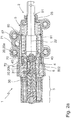
- the locking unit 1 according to the invention is shown schematically in a first embodiment.
- the locking unit 1 has a housing 5, at the front housing end 50 of which an opening 51 is provided, from which the front end 21 of the piston 2 protrudes.
- an electromagnet 3 connects to the housing 5 in the axial direction.
- Axial direction here means either the axis of symmetry or longitudinal axis 22 of the piston 2 or else the direction of movement of the piston 2.
- the piston 2 is movably mounted in the housing 5 in the axial direction, in particular along its longitudinal axis 22.
- a drive is provided for the movement of the piston 2, in particular the piston 2 can be acted upon with pressure, preferably with hydraulic pressure, the force component of this pressure being directed against the direction of force of a piston spring 23.
- the piston spring 23 is supported on the one hand on a housing shoulder or shoulder 53 of the housing 5 which adjoins the housing end 50 on the inside.
- the piston spring 23 is supported on a flange ring 24 of the piston 2. This flange ring 24 lies inside, centrally in the housing 5.
- the piston 2 moves due to the pressure between several positions, in the variant shown here, for example, two Positions provided.
- the position of the piston 2 in the respective positions can be determined by a latching unit 4, which is equipped with latching elements 40.
- the electromagnet 3 or its elements serve to actuate the latching unit 4, in particular for its latching elements 40.
- the electromagnet 3 has a coil body 32 which carries a winding 33. This has a wire through which electrical current can flow.
- the winding 33 is closed radially on the outside (with respect to the longitudinal axis 22) by a magnet housing 34. A magnetic field is created by energizing the winding 33.
- An armature space 35 is provided in the interior of the coil body 32, the armature space 35 in the present case filling approximately half of the interior of the coil body 32.
- the armature space 35 is oriented in the direction of the piston 2.
- the remaining area of the interior of the coil body 32 is filled by a magnetic core 36, which, as usual, consists of soft magnetic material that guides the magnetic field lines well.
- an armature 30 which in the exemplary embodiment shown here is cylindrical and has a bottom surface 37.
- An air gap 39 is formed between the bottom surface 37 and an end surface 38 of the magnetic core 36 facing the armature space 35.
- a magnetic spring 300 pushes the armature 30 to the right, so that the air gap 39 has its maximum expansion. If the winding 33 is energized, it generates a magnetic field which presses the armature 30 to the left against the force of the magnetic spring 300, so that the air gap 39 is closed.
- the anchor 30 carries an anchor rod 31.
- the anchor rod 31 is oriented concentrically to the anchor 30, anchor 30 and anchor rod 31 are movably mounted in the armature space 35 in the axial direction, ie parallel to the longitudinal axis 22.
- the construction is selected so that the armature 30 has an axial bore 301 which receives the armature rod 31.
- the anchor rod 31 protrudes from the anchor 30 on both sides thereof.
- An axial bore 302 is also provided in the magnetic core 36.
- the arrangement is chosen such that there is a bearing for the anchor rod 31 in this axial bore 302.
- the armature space 35 is delimited on one side by the magnetic core 36, the magnetic core 36, as already described, filling the part of the interior of the coil body 32 facing away from the piston 2 and thus also the axial end of the electromagnet 3, but also the locking unit 1 , together with the magnet housing 34, describes.
- the armature space 35 is delimited by a yoke part 41 which is pot-shaped and is preferably made of soft magnetic material in order to guide the magnetic field lines well. A part of the armature 30 is immersed in the cup-shaped yoke part 41.
- the yoke part 41 is part of the locking unit 4.
- the yoke part 41 has a penetration hole 47 which receives the anchor rod 31 and, if necessary, also supports it.
- the locking unit 4 is, seen in section, essentially H-shaped.
- the radially oriented web of the H forms the yoke part 41.
- This is followed by a first axial section 48 and a second axial section 49.
- the two axial sections 48, 49 of the H adjoining on both sides of the web are of different sizes or lengths, the section 49 facing the armature space 35 being significantly shorter axially than the section 48 facing the piston 2.
- the larger section 48 there In the present case or in typical designs, about 2 to 3, 3.5 or 4 times larger or longer than the smaller section 49.
- a radially extending (based on the longitudinal axis 22) compensation opening 405 is arranged in the foot region of the sleeve-like first axial section 48 facing the yoke part 41.
- This compensating opening 405 fluidly connects an inner space 42 to an outer space 406, in which a piston pressure piece 26 of the piston 2 moves axially. Pressure equalization between the inner space 42 and the outer space 406 is possible through the equalizing opening 405.
- the two sections 48, 49 each radially close off a corresponding receiving space.
- the smaller second section 49 delimits the armature space 35 (this is the pot-like yoke part 41) and the larger section 48 the interior 42.
- the interior 42 extends in the axial direction.
- the magnetic spring 300 is also provided, which is supported on the one hand on the upper side of the yoke part 41 facing the second section 49 and on the other hand on a control element 43 which is arranged at the end on the anchor rod 31.
- the control element 43 is arranged in a fixed position on the anchor rod 31.
- the control element 43 also has a receiving bore 401 into which the anchor rod 31 is inserted.
- the control element 43 is pressed in a suitable manner with the anchor rod 31 and is thus held in an exact position on it.
- the control element 43 essentially consists of two different geometrical bodies, a cylinder section and a cone section, the cone section forming a cone surface 400 on its outer surface.
- a lateral surface 403 of the cylinder section of the control element 43 is guided on an inner wall 402 which radially delimits the inner space 42, if appropriate also stored.
- At the axial end of the control element 43 facing the electromagnet 3 there is an annular recess 404 in which the end of the magnetic spring 300 protrudes and is thus reliably guided and held.
- the conical surface 400 is located at the end of the control element 43 opposite the recess 404.
- control element 43 It is clear that other constructions are also possible for the configuration of the control element 43. It is also conceivable, for example, that the conical surface on the control element is arranged on the side facing the electromagnet 3 and then the functioning of the locking unit 1 is changed if necessary.
- the control element urges the detent elements 40, which are designed as balls, radially outward and thus blocks the piston 2. The movement of the piston 2 can also be blocked when the electromagnet 3 is energized.
- the position of the air gap 39 is also variable according to the proposal.
- the embodiment shown is the air gap 39 on the side of the armature 30 facing away from the latching unit 4, that is to say between the armature 30 and the magnetic core 36.
- the air gap it is also possible for the air gap to then be between the armature 30 and the yoke part 41, that is to say the one Detent unit 4 facing side of the armature 30 is formed.
- the arrangement of the magnetic spring 300 in the interior 42 is advantageous since these elements do not impair the magnetic circuit that is formed in the elements around the armature space 35.
- an arrangement of the magnetic spring in the armature space or also outside of the locking unit 4 is possible in order to form a corresponding energy store.
- the air gap 39 closes by displacing the armature 30 to the left, as a result of which the armature rod 31 and the control element 43 carried by the armature rod 31 are also displaced to the left, as a result of which the magnetic spring 300 is compressed and thus an energy store for a return movement of the armature 30 - armature rod 31 - control element 43 forms when switching off the energization of the winding 33.
- the larger first section 48 of the latching unit 4 carries, at its end or end region 44 facing away from the yoke part 41, the latching element or elements 40, which in the present case are designed as balls.
- the larger section 48 (at least in the end region 44) is formed like a sleeve or cylinder.
- the locking elements 40 are provided as balls 40 in a ball cage.
- the sleeve-like or cylinder-like end region 44 of the section 48 has radially (with respect to the longitudinal axis 22) oriented bores 45 for receiving the latching elements 40 or balls.
- the detent elements 40 or balls 40 may or may not deflect radially inwards.
- the piston 2 consists of two individual parts.
- the piston 2 comprises a piston tube 25 which partially protrudes from the opening 51, and a piston pressure piece 26 which is produced separately therefrom.
- the arrangement is chosen such that the piston pressure piece 26 in the housing 5 connects to the inner end of the piston tube 25.
- the piston tube 25 is completely hollow on the inside. This is preferably formed as a deep-drawn part, for example made of metal such as tool steel or the like, as a result of which the manufacture of such an element is considerably cheaper.
- the wall thickness of the piston tube 25 in the present case is therefore only about 5 to about 15 percent of the diameter of the piston tube 25, or of the outside diameter of individual parts (e.g. inner end 27, first tube center piece 29, second tube center piece 202 and connection area 203) of the piston tube 25.
- the piston tube 25 bears against the piston pressure piece 26 with its flange ring 24 provided at the end.
- the flange ring 24 thus forms a radially oriented (with respect to the longitudinal axis 22) boundary surface of the piston tube 25.
- This inner end 27, which also includes the flange ring 24, is pushed onto the connecting ring 28, which closes off the piston pressure piece 26 in the direction of the piston tube 25 .
- a relatively precise fit can be provided here, and for example the piston tube 25 can be pressed onto the piston pressure piece 26 in this way.
- other connection methods such as welding, soldering or gluing the elements of the piston tube 25 and piston pressure piece 26 are alternatively possible.
- the end 27 then merges into a first tube center piece 29 in a taper 200, ie the diameter of the piston tube 25 in the area of the first tube center piece 29 is smaller than in the area of the end 27.
- the first tube center piece 29 then closes with another one designed as a shoulder second taper 201 to the second pipe center piece 202.
- the diameter of the piston tube 25 in the area of the second tube center piece 202 is smaller than in the area of the first tube center piece 29.
- This second taper 201 forms a stop.
- the piston 2 is guided in a slide bearing 54. This has an inner flange 55. If the piston 2 is shifted to the right, the movement is limited in that the shoulder-like taper 201 rests on the radially acting inner flange 55 of the slide bearing 54. Such a state is, for example, in Fig. 2b shown.
- the slide bearing 54 On the inside of the opening 51 of the housing 5, the slide bearing 54 just mentioned is provided for the piston tube 25.
- the second pipe center piece 202 is mounted on this slide bearing 54.
- the plain bearing 54 has an inner flange 55 oriented into the housing interior, which also forms the shoulder 53 in this area. Since the housing 5 is preferably made of plastic, this part is overmolded accordingly. However, it is also possible for the slide bearing 54 to be inserted into a separately produced, for example injection-molded, housing 5, for example a plastic housing. A relatively high accuracy is preferably advantageous here, that is to say in the region of the opening 51 and the embedding of the sliding bearing 54 in the housing 5.
- the piston 2 In the position of the locking unit 1 shown here, the piston 2 is fully inserted into the housing 5 and only the end-side connection region 203 of the piston 2 protrudes from the housing 5. Further elements, not shown here, which are moved or held by the piston 2, are connected to the piston 2 in the connecting region 203.
- the second pipe center piece 202 merges into the connecting area 203 in the third taper 204.
- all axial sections that is to say the inner end 27, the first taper 200, the first pipe center piece 29, the second pipe taper 201, the second pipe center piece 202, the third taper 204 and the connecting region 203 are hollow on the inside.
- connection area 203 has a recess provided on the central plane, that is to say it is slotted.
- a fork-like structure of the connection area 203 is formed, the remaining half-shells 211 of the connection area 203 nevertheless providing sufficient stability for the connection to a further element (not shown further).
- a bore or other penetration opening 210 is provided in the half-shell 211 for receiving a fastening bolt or the like.
- the piston pressure piece 26 is also essentially sleeve-like, that is to say hollow on the inside. Its outer surface 205 serves as a guide. At the front end facing the piston tube 25, an outer ring 206 is provided on the piston pressure piece 26. Its outer surface is mounted on an inner wall 56 of the housing, or at least guided. The outer ring 206 bears in the axial direction (based on the longitudinal axis 22) on the flange ring 24 of the piston tube 25. A pressure side 207 of the outer ring 206 facing away from the flange ring 24 is pressurized, preferably with hydraulic pressure, and is therefore also correspondingly solid. An annular pressure chamber 70 is provided here.
- the piston pressure piece 26 is therefore preferably realized as a turned part. It is preferably made of tool steel.
- a circumferential shoulder 208 is provided radially on the outside on the pressure side 207, which receives a 0-ring seal or a sealing ring 209. Since this 0-ring seal or the sealing ring 209 is exposed to the hydraulic pressure, it is also pressed in the radial direction and thus reliably closes a gap that may still remain between the radial outer surface of the outer ring 206 and the housing inner wall 56.
- a center piece 6 is also provided.
- the middle piece 6 is also sleeve-shaped and forms a bearing surface 60 for the piston pressure piece 26 on its inside.
- the bearing surface 60 acts together with the outer surface 205 of the piston pressure piece 26.
- the middle piece 6 is fixed in the locking unit 1.
- the center piece 6 is provided as a turned part and preferably consists of a common tool steel.
- the center piece 6 is designed as a sintered molded part or is produced in a formative process, in particular by means of 3D printing, metal powder injection molding, selective laser melting or selective laser sintering. Sintering or formative manufacturing are cost-effective manufacturing processes that can also be used to produce workpieces of almost any shape in a single operation.
- the center piece 6 has an axial length (in relation to the longitudinal axis 26).
- the axial length of the center piece 6 corresponds to approximately 100-200%, preferably approximately 130-170%, of the stroke of the piston 2.
- the axial length of the middle piece 6 corresponds to approximately 20-50%, preferably approximately 30-40%, of the axial length of the piston 2.
- the axial length of the middle piece 6 corresponds to approximately 10-30%, preferably approximately 13-20%, of the axial length of the locking unit 1.
- the outer surface 205 is the outer surface of a cylinder.
- the outer surface 205 bears on its side facing away from the piston tube 25
- the end facing the electromagnet 3 has a further O-ring seal 213 in a circumferential groove 212. This O-ring seal 213 seals the gap between the outer surface 205 and the bearing surface 60, which is under pressure, in the direction of the electromagnet 3.
- Piston 2 shown consists of the two components, the piston tube 25 and the piston pressure piece 26, which are mechanically firmly connected to one another in the variant shown here, for example because they are attached or pressed. Alternatively, they can also be designed so that they are flying towards one another, that is to say only because of the force effect of the pressure applied on the one hand and the force of the piston spring 23 directed against it on the other hand.
- This piston 2 which consists of two components, is initially supported by the piston pressure piece 26 on the bearing surface 60 of the center piece 6.
- Another bearing is alternatively provided on the outer ring 206 of the piston pressure piece 26 in cooperation with the inner wall 56 of the housing.
- the second tube center piece 202 of the piston tube 25 is mounted on the plain bearing 54 provided on one side.
- An inner surface 214 of the piston pressure piece 26 is also not smooth, but rather has bulges or latching receptacles 20, 20a, 20b that are axially spaced from one another (with respect to the longitudinal axis 22).
- the diameter of the ring-like bulges or snap-in receptacles 20, 20a, 20b is larger than the diameter of the inner surface 214 lying between them.
- the locking receptacles 20, 20a, 20b are screwed into the inner surface 214 of the sleeve-like piston pressure piece 26 as a shoulder or an internal shoulder.
- the latching unit 4 is arranged in a stationary manner in the housing 5, the piston 2 is axially or executed longitudinally. In the in Figure 1a shown position, however, the movement of the piston 2 to the right, in the direction of the opening 51, is blocked by the latching unit 4, the locking unit 1 is blocked in the retracted position of the piston 2.
- the latching unit 4 has latching elements 40, each of which is movably mounted radially (with respect to the longitudinal axis 22) in bores 45, for example balls 40 of a ball cage.
- the electromagnet 3 is shown in a dropped position, that is, the winding 33 is not supplied with current. Therefore, the air gap 39 is formed between the armature 30 and the magnetic core 36, since the magnetic spring 300 displaces the armature 30 to the right and thus also the control element 43, on which the magnetic fields 300 are supported.
- the control element 43 arrives at the axial position of the locking elements / balls 40 such that the conical surface 400 of the control element 43 acts on the locking elements / balls 40 and these radially (with respect to the longitudinal axis 22) to the outside, into the respective locking receptacles 20, 20a pushes. Then, however, a longitudinal movement of the piston 2, that is to say a movement of the piston 2 to the right, is blocked, since a first inner shoulder 215a, which delimits the latching receptacle 20, 20a, bears against the latching elements 40 which are offset radially outward.
- the first inner shoulder 215a is located on the first latching seat 20a on the side facing the second latching seat 20b.
- the second inner shoulder 215b is located on the side of the second latching seat 20b facing the first latching seat 20a.
- the two latching receptacles 20a and 20b are axially spaced apart (with respect to the longitudinal axis 22).
- the piston 2, in particular the piston pressure piece 26, is movably supported between the radially inside latching unit 4 and the radially outside center piece 6.
- the middle piece 6 takes a central position in the locking unit 1.
- it carries the sleeve-like housing 5 on its radial outer side 62.
- it also establishes a connection with the electromagnet 3, in particular with its magnet housing 34.
- a radially extending gap 65 can be seen in the lower region between the magnet housing 34 and the housing 5, which extends radially on the inside into a channel 66a which is in fluidic contact with an intermediate space 66b which results between the pressure piece 26 and the latching unit 4 .
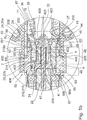
- the radially extending channel 66a is realized so that on one Electromagnet 3 facing foot area 68 (see 3a and 3b ) of the middle piece 6, a recess 67 (see 3a and 3b ) is provided and so the foot region 68 of the center piece 6 facing the electromagnet 3 does not abut the entire circumference of the flange part of the coil body 32.
- the fluidically connected elements intermediate space 66b, channel 66a and gap 65 allow the interior of the locking unit 1 to be vented.
- center piece 6 radially aligns the electromagnet 3 with the latching unit 4. In this area, it is advantageous to achieve a high concentricity.
- the center piece 6 has, on its side facing away from the electromagnet 3 or facing the piston tube 25, a circumferential contact shoulder 63, to which an annular and / or cone-like connection area 64 then adjoins.
- This connection area 64 is part of the center piece 6.
- the proposal according to the invention is very variable for the design of the connection area 64.
- the connection area 64 has several tasks.
- the pipe section 57 is pushed or pressed onto the preferably ring-like area of the connecting area 64.
- the piston 2, in particular the piston pressure piece 26 bears against the inner wall 56 of the housing, in this respect the pipe piece 57 has the properties of a cylinder. This preferably limits or guides Pipe piece 57 not only the pressure on its housing inner wall 56, but also on its pipe outside 58th
- the mounting of the first end piece of the tube piece 57 on the middle piece 6 underlines the central importance of the middle piece 6 in the embodiment shown here.
- the second end piece of the pipe section 57 is mounted in the housing 5 and the inside of the pipe section 57 serves as a bearing or guide for the piston 2.
- the pipe section 57 is connected to the housing 5 in a fluid-tight manner on the right-hand side. This is achieved in that the pipe section 57 is inserted into a groove 80 in the housing 5.
- the groove 80 is annular and is delimited radially on the inside by a projection 81 of the housing 5.
- the fluid-tight connection ensures that fluid under pressure, which is located in the pressure line channel 71, does not reach a region radially outside of the piston tube 25 at the connection point between the housing 5 and the pipe section 57, which causes a movement of the piston 2 to the right, which would just be achieved by the pressurized fluid as described below, would counteract.
- Possible versions of a tight connection are in the Figures 4a to 4c are shown and are described below.
- Pressure connection On the housing 5 is a, in Figure 1a Pressure connection, not shown, which provides a medium under pressure as a drive for the piston 2.
- This pressure connection is preferably arranged in the half of the housing 5 facing the opening 51, in particular it is located close, in particular very close to the opening 51.
- the pressure side 207 of the piston pressure piece which can be pressurized must be provided 26 in the retracted position of the piston 2 as far as possible from the opening 51.
- This boundary condition means that in the housing 5, or in the locking unit 1, the medium under pressure is initially opposite to the preferred direction of movement (the working movement realized by the pressurization) Figure 1a must be directed to the right) of the piston 2 in order to then be deflected at a suitable point and guided to the pressure side 207.
- the pressure connection is therefore in fluid communication with the pressure line channel 71, which runs essentially axially (with respect to the longitudinal axis 22).
- This pressure line channel 71 is radially inside from the outside 58 of the pipe section 57 and radially outside from the plastic housing 5, in particular the inside wall 500 thereof limited.
- the pressure line channel 71 can encompass the entire pipe section 57 (in relation to its circumferential direction) or only in one segment, as in FIG Figure 1a shown to extend axially.
- the pipe section 57 Since, according to one embodiment, the pipe section 57 is fixed, and therefore also tight or pressure-tight, it is plugged onto the connection area 64 of the center piece 6, an opening 501 is provided in the pipe section 57 at the axial height, based on the longitudinal axis 22, of the connection area 64 which the pressurized medium passes from the pressure line channel 71 into the pressure chamber 70 on the inside of the pipe section 57.
- the pipe section 57 thus has a plurality of tasks.
- Its inner wall 56 serves as a guide or bearing for the piston 2. Its outer side 58 serves at least partially as a pressure line channel 71.
- the pipe section 57 supports or stiffens the housing 5, which is preferably made of plastic.
- This combined design of the housing 5 combines low mass and inexpensive manufacture with high wear resistance and therefore with high availability of a locking unit equipped in this way.
- the tube piece 57 is surrounded at its end 59 facing away from the connection region 64 in a ring-like manner by the plastic material of the housing 5. Therefore, the pressure line channel 71 does not necessarily extend over the entire axial length of the pipe section 57.
- the pipe section 57 can be encapsulated by the plastic of the housing 5, alternatively, for example, the pipe section 57 can be inserted or pressed into a housing 5 produced in a separate manufacturing step become.
- the center piece 6 is formed like a sleeve. It has a foot region 68 facing the electromagnet 3 in the installed state, to which a central section 69 adjoins. On the side facing away from the foot area 68, the middle piece 6 is closed off by a connecting area 64.
- the middle section 69 has the largest diameter and, in the installed state, lies directly against the plastic material of the housing 5.
- the diameter of the foot region 68 is smaller than the diameter of the middle section 69.
- the foot region 68 is not completely designed as a circumferential ring, but rather has a recess 67 in a certain angular segment, which forms the channel 66a in the installed state.
- the central section 69 merges with the radially extending contact shoulder 63 into the connection area 64.
- the outer diameter of the connecting area 64 is also smaller than the diameter of the central section 69.
- the pipe section 57 is plugged onto the connecting area 64 in the installed state.
- a plurality of support segments 600 are provided in the connection area 64, which are formed as jacket segments on the cylindrical outer surface of the connection area 64 and are each separated by segment gaps 72.
- These segment gaps 72 are formed as recesses in the lateral surface of the connection area 64 and carry the medium, so the corresponding operating pressure prevails in the segment gaps 72 when installed and in operation.
- the segment gaps 72 are therefore part of the medium-carrying system.
- the embodiment of the center piece 6 after Figure 1a or 1b differs as follows: As already stated, there is a fluidic connection between the pressure line channel 71, which is arranged on the radial outside of the pipe section 57, and the pressure chamber 70, which is arranged on the radial inside of the pipe section 57. In the in the Figures 1a and 1b Example shown, this connection is realized through the opening 501 in the pipe section 57. The end 502 of the pipe section 57 facing the center piece 6 is completely pushed onto the connection area 64 and lies snugly (and thus also sealingly) against the radially outward-extending contact shoulder 63.
- the Figures 2a and 2 B show the use of the center piece 6 according to the Figures 3a and 3b . It can be clearly seen that the end 502 facing the center piece 6 is axially spaced (with respect to the longitudinal axis 22) from the contact shoulder 63. The in axial The segment gaps 72 extending in the direction (with respect to the longitudinal axis 22) are thus fluidly connected to the pressure line channel 71 and also the pressure chamber 70.
- the axial distance (based on the longitudinal axis 22) of the pipe end 502 to the contact shoulder 63 corresponds here to the opening 501, and here forms a radial connection from the inside of the pipe section 57 to the outside of the pipe section 57. This connection runs outside the pipe section 57, that is to say axially offset to the end of the pipe section 502.
- FIG. 2a and 2 B a second embodiment of the locking unit 1 according to the invention is shown in two different positions of the piston each in a vertical section.
- the blocking position of the latching unit 4 is realized in the dropped, ie not energized state of the electromagnet 3, but without defining the invention thereon, the blocking position can alternatively also be realized in the energized state of the electromagnet.
- FIGS. 4a to 4c each show a section of the connection point between the pipe section 57 and the housing 5, different possibilities of fastening and sealing being described.
- the pipe section 57 is received in a groove 80 which is annular and is delimited radially on the inside by a projection 81.
- a seal 82 in the form of a sealing ring is arranged between the housing 5 and the pipe section 57. This ensures a fluid-tight design.
- a seal 83 in the form of sealing material made of silicone is arranged to the side of the pipe section 57, which ensures the fluid-tight design. A holding of the pipe section 57 in the groove 80 can also be achieved.
- a number of bores 84 are formed in the pipe section, through which an engagement part 85 of the housing 5 passes. This can be done, for example, by injecting the housing 5 around the pipe section 57 during manufacture.
- the engagement part 85 can thus be connected to the rest of the housing 5 in a material-locking manner and thus ensure an advantageous fastening of the blank 57.
- end of the pipe section 57 can also be extrusion-coated without the arrangement of bores 84.
- the plastic material of the housing 5 can, for example, at least at the end of the pipe section 57 rest against the inside (through the projection 81) and outside.
- the invention includes: A locking unit, in particular for the parking lock of an automatic transmission, for locking the movement of a piston (2) which can be moved by a drive and in particular can be acted upon by pressure or hydraulic pressure, the locking unit (1) comprising an electromagnet (3) and at least one latching element ( 40) and the locking element (40) interacts with the armature (30) or the armature rod (31) of the electromagnet (3) and the piston (2) has at least one locking receptacle (20, 20a, 20b) and the piston (2) can be fixed by the holding interaction of the locking element (40) with the locking receptacle (20, 20a, 20b), the locking unit (1) having an inner tube piece (57) which is designed as a guide for the piston (2).
- sealing means is a sealing ring (209) or an O-ring.
- the above-mentioned locking unit, the pipe section (57) being straight and / or cylindrical in shape at least along a section on which the piston (2) is guided.
- the above-mentioned locking unit, the middle piece (6) being designed like a sleeve.
- the above-mentioned locking unit wherein the middle piece (6) is designed as a turned part or sintered molded part, is produced in a formative process or is produced by means of 3D printing, metal powder injection molding, selective laser melting or selective laser sintering.
- the above-mentioned locking unit the middle piece (6) having a radial outside (62) which supports the housing (5).
- the above-mentioned locking unit a number of segment gaps (72) being formed as notches in the connecting region (64) radially on the outside.
- segment spaces (72) are designed as a fluidic connection between the pressure line channel (71) and a pressure space (70) within the pipe section (57).
- connection area (64) being designed as a crown ring.
- the above-mentioned locking unit wherein the cavity has a wall, continuously or in sections, which is thinner than a quarter of a diameter of the piston (2) or thinner than a tenth of the diameter of the piston (2).
- the above-mentioned locking unit wherein the piston (2) has a completely hollow piston tube (25) along an axial section and a piston pressure piece (26) connected to the piston tube (25) along another axial section.
- the above-mentioned locking unit, the piston tube (25) being designed as a deep-drawn part, from tool steel or from metal.
- the above-mentioned locking unit the piston tube (25) having a tube center piece (29) with an outside taper (201), the taper (201) of the piston tube (25) interacting with a shoulder (53) formed in the housing (5), to limit movement of the piston (2) away from the electromagnet (3).
- the above-mentioned locking unit having a locking unit (4) which carries the locking elements (40).
- the above-mentioned locking unit, the latching unit (4) having a section (49) facing the electromagnet (3) or an armature space (35) of the electromagnet (3) and a section (48) facing the piston (2), each of which is sleeve-shaped are executed.
- the above-mentioned locking unit, the outer space (406) and the inner space (42) being fluidly connected via a compensation opening (405) formed in the latching unit (4).
- control element (43) is at least partially movable within the section (48) facing the piston (2).
- the above-mentioned locking unit, the latching elements (40) being spherical.
- control element (43) is designed to press the latching elements (40) radially outwards at least in one position.
- the above-mentioned locking unit, the latching unit (4) and the center piece (6) being formed in one piece.
- the above-mentioned locking unit wherein the piston (2) has at least two locking receptacles (20a, 20b) which are axially spaced apart.
- connection area (203) is designed like a fork.
- connection area (203) is designed as a stamped fork head.
- the above-mentioned locking unit having a winding (31) for generating a magnetic field for moving the armature (30) and / or the armature rod (31).
- the above-mentioned locking unit wherein the locking unit (4) and the center piece (6) are produced as a one-piece injection molded part or in one piece in an additive manufacturing process, by means of which a number of radial recesses, in particular bores (45), for receiving the locking elements (40 ) is formed in the locking unit (4).
- seal (82) is an O-ring or sealing ring.
- the aforementioned locking unit, wherein the seal (83) is a sealing material or a silicone sealing material.
- the above-mentioned locking unit the housing (5) having an in particular ring-like projection (81) which partially encompasses the pipe section (57).
Landscapes
- Engineering & Computer Science (AREA)
- General Engineering & Computer Science (AREA)
- Mechanical Engineering (AREA)
- Actuator (AREA)
- Pistons, Piston Rings, And Cylinders (AREA)
Abstract
Die Erfindung betrifft eine Verriegelungseinheit, insbesondere für die Parksperre eines Automatikgetriebes, für das Verriegeln der Bewegung eines von einem Antrieb bewegbaren, insbesondere mit Druck bzw. hydraulischen Druck beaufschlagbaren Kolbens, wobei die Verriegelungseinheit ein innenliegendes Rohrstück aufweist, welches als Führung des Kolbens ausgebildet ist.The invention relates to a locking unit, in particular for the parking lock of an automatic transmission, for locking the movement of a piston which can be moved by a drive, in particular to which pressure or hydraulic pressure can be applied, the locking unit having an inner tube piece which is designed as a guide for the piston.
Description
Die Erfindung betrifft eine Verriegelungseinheit, insbesondere für die Parksperre eines Automatikgetriebes, für das Verriegeln der Bewegung eines von einem Antrieb bewegbaren, insbesondere mit Druck bzw. hydraulischen Druck beaufschlagbaren Kolbens, wobei die Verriegelungseinheit einen Elektromagneten und mindestens ein Rastelement aufweist und das Rastelement mit dem Anker beziehungsweise der Ankerstange des Elektromagneten zusammenwirkt und der Kolben mindestens eine Rastaufnahme aufweist und der Kolben durch das haltende Zusammenwirken des Rastelementes mit der Rastaufnahme festlegbar ist.The invention relates to a locking unit, in particular for the parking lock of an automatic transmission, for locking the movement of a piston which can be moved by a drive, in particular to which pressure or hydraulic pressure can be applied, the locking unit having an electromagnet and at least one locking element and the locking element with the armature or the armature rod of the electromagnet cooperates and the piston has at least one latching receptacle and the piston can be fixed by the holding interaction of the latching element with the latching receptacle.
Eine gattungsgemäße Verriegelungseinheit ist zum Beispiel aus der Internationalen Patentanmeldung
Es ist eine Aufgabe der Erfindung, eine bekannte Verriegelungseinheit alternativ oder besser auszuführen. Dies wird erfindungsgemäß durch eine Verriegelungseinheit gemäß Anspruch 1 erreicht. Vorteilhafte Ausführungen können beispielsweise den Unteransprüchen entnommen werden.It is an object of the invention to carry out a known locking unit alternatively or better. This is achieved according to the invention by a locking unit according to
Die Erfindung betrifft eine Verriegelungseinheit, insbesondere für die Parksperre eines Automatikgetriebes, für das Verriegeln der Bewegung eines von einem Antrieb bewegbaren, insbesondere mit Druck bzw. hydraulischen Druck beaufschlagbaren Kolbens, wobei die Verriegelungseinheit einen Elektromagneten und mindestens ein Rastelement aufweist und das Rastelement mit dem Anker beziehungsweise der Ankerstange des Elektromagneten zusammenwirkt und der Kolben mindestens eine Rastaufnahme aufweist und der Kolben durch das haltende Zusammenwirken des Rastelementes mit der Rastaufnahme festlegbar ist.The invention relates to a locking unit, in particular for the parking lock of an automatic transmission, for locking the movement of a piston which can be moved by a drive, in particular to which pressure or hydraulic pressure can be applied, the locking unit having an electromagnet and at least one locking element and the locking element with the armature or the armature rod of the electromagnet cooperates and the piston has at least one latching receptacle and the piston can be fixed by the holding interaction of the latching element with the latching receptacle.
Erfindungsgemäß weist die Verriegelungseinheit ein innenliegendes Rohrstück auf, welches als Führung des Kolbens ausgebildet ist.According to the invention, the locking unit has an inner tube piece which is designed as a guide for the piston.
Das innenliegende Rohrstück kann allgemein als Teil der Verriegelungseinheit oder als Teil des Gehäuses betrachtet werden.The inner tube piece can generally be considered part of the locking unit or part of the housing.
Durch die Führung am Rohrstück wird eine besonders gute Führung des Kolbens erreicht, so dass dieser möglichst leichtgängig bewegt werden kann.The guidance on the pipe section results in particularly good guidance of the piston, so that it can be moved as smoothly as possible.
Außenseitig zu dem Rohrstück kann insbesondere ein Druckleitungskanal ausgebildet sein. In diesen kann ein unter Druck stehendes Medium einströmen, um den Kolben zu betätigen. Beispielsweise durch eine weiter unten beschriebene Dichtigkeit zwischen Rohrstück und Gehäuse kann das Medium vorteilhaft an eine Position geleitet werden, an welcher es zum Antrieb des Kolbens benötigt wird.A pressure line channel can in particular be formed on the outside of the pipe section. A medium under pressure can flow into this in order to actuate the piston. For example, due to the tightness between the pipe section and the housing described below, the medium can advantageously be directed to a position at which it is required to drive the piston.
Bevorzugt ist vorgesehen, dass der Kolben zumindest teilweise in einem Gehäuse gelagert oder angeordnet ist.It is preferably provided that the piston is at least partially mounted or arranged in a housing.
Gemäß einer bevorzugten Ausführung ist vorgesehen, dass das Gehäuse zumindest teilweise, vorzugsweise vollständig aus Kunststoff gebildet ist. Dies hat sich als vorteilhaft erwiesen, insbesondere wegen der leichten Bearbeitbarkeit und des geringen Gewichts. Auch andere Materialen sind jedoch möglich.According to a preferred embodiment, it is provided that the housing is at least partially, preferably completely, made of plastic. This has proven to be advantageous, in particular because of the easy workability and the low weight. However, other materials are also possible.
Der Druckleitungskanal ist bevorzugt zumindest teilweise radial, bezogen auf die Längsachse des Kolbens, innen von der Außenseite des Rohrstückes und außen von der Innenwand des Gehäuses begrenzt.The pressure line channel is preferably at least partially radially, with respect to the longitudinal axis of the piston, delimited on the inside by the outside of the pipe section and on the outside by the inside wall of the housing.
Das Rohrstück kann mit dem Gehäuse verbunden sein oder Teil des Gehäuses sein.The pipe section can be connected to the housing or be part of the housing.
Bevorzugt liegt der Kolben am Rohrstück an. Dies erlaubt eine besonders vorteilhafte Führung des Kolbens entlang des Rohrstücks. Das Anliegen kann entlang eines vollständigen Umfangs erfolgen.The piston preferably lies against the pipe section. This allows a particularly advantageous guidance of the piston along the pipe section. The request can be made along a full scope.
Bevorzugt ist vorgesehen, dass der Kolben am Rohrstück entlanggleitet.It is preferably provided that the piston slides along the pipe section.
Gemäß einer bevorzugten Ausführung liegt der Kolben fluiddicht am Rohrstück an. Dadurch kann der Kolben vorteilhaft durch Druck betätigt werden.According to a preferred embodiment, the piston rests on the pipe section in a fluid-tight manner. As a result, the piston can advantageously be actuated by pressure.
Bevorzugt weist der Kolben ein Dichtmittel auf, welches den Kolben am Rohrstück fluiddicht abdichtet. Dies erlaubt eine besonders dichte Ausführung.The piston preferably has a sealant which seals the piston on the pipe section in a fluid-tight manner. This allows a particularly tight execution.
Das Dichtmittel kann beispielsweise ein Dichtring oder ein O-Ring sein. Der Dichtring oder der O-Ring können insbesondere in einem umlaufenden Absatz des Kolbens vorgesehen sein.The sealant can be, for example, a sealing ring or an O-ring. The sealing ring or the O-ring can in particular be provided in a circumferential shoulder of the piston.
Der Dichtring oder der O-Ring sind bevorzugt in einem Kolbendruckstück des Kolbens vorgesehen.The sealing ring or the O-ring are preferably provided in a piston pressure piece of the piston.
Bevorzugt bildet das Rohrstück innenseitig eine Gehäuseinnenwand, an welcher der Kolben anliegtThe inside of the tube piece preferably forms an inner wall of the housing against which the piston rests
Das Rohrstück ist bevorzugt zumindest entlang eines Abschnitts, an welchem der Kolben geführt wird, gerade und/oder zylinderförmig ausgebildet. Dies erlaubt ein vorteilhaftes Zusammenwirken mit dem Kolben.The pipe section is preferably straight and / or cylindrical in shape at least along a section on which the piston is guided. This allows an advantageous interaction with the piston.
Bevorzugt ist das Rohrstück aus Metall oder aus Kunststoff ausgebildet. Diese Materialien haben sich als vorteilhaft erwiesen. Auch die Verwendung anderer Materialien ist jedoch möglich.The piece of pipe is preferably made of metal or plastic. These materials have proven to be advantageous. However, the use of other materials is also possible.
Gemäß einer bevorzugten Ausführung ist vorgesehen, dass der Kolben zumindest teilweise in einem, zumindest teilweise von dem Gehäuse umgebenen Mittelstück gelagert ist.According to a preferred embodiment, it is provided that the piston is at least partially supported in a middle piece that is at least partially surrounded by the housing.
Das Mittelstück kann insbesondere hülsenartig ausgebildet sein.The center piece can in particular be designed like a sleeve.
Bevorzugt bildet das Mittelstück an einer Innenseite eine Lagerfläche für den Kolben oder ein Kolbendruckstück des Kolbens. Dadurch kann der Kolben vorteilhaft gelagert werden.The center piece preferably forms a bearing surface for the piston or a piston pressure piece of the piston on an inside. As a result, the piston can be advantageously stored.
Das Mittelstück kann insbesondere als Drehteil oder Sinterformteil ausgebildet sein, in einem formativen Verfahren hergestellt sein oder mittels 3D-Druckens, Metallpulverspritzgießens, selektiven Laserschmelzens oder selektiven Lasersinterns hergestellt sein. Derartige Verfahren haben sich als vorteilhaft erwiesen. Auch andere Verfahren sind jedoch möglich.The center piece can in particular be designed as a turned part or sintered molded part, be produced in a formative process or be produced by means of 3D printing, metal powder injection molding, selective laser melting or selective laser sintering. Such methods have proven to be advantageous. However, other methods are also possible.
Bevorzugt weist das Mittelstück eine axiale Länge von 100 % bis 200 % oder von 130 % bis 170 % eines Hubs des Kolbens auf.The middle piece preferably has an axial length of 100% to 200% or of 130% to 170% of a stroke of the piston.
Weiter bevorzugt weist das Mittelstück eine axiale Länge von 30 % bis 40 % einer axialen Länge des Kolbens auf.More preferably, the middle piece has an axial length of 30% to 40% of an axial length of the piston.
Weiter bevorzugt weist das Mittelstück eine axiale Länge von 13 % bis 20 % einer axialen Länge der Verriegelungseinheit auf.More preferably, the middle piece has an axial length of 13% to 20% of an axial length of the locking unit.
Bevorzugt weist das Mittelstück eine radiale Außenseite auf, welche das Gehäuse trägt. Dies erlaubt eine zuverlässige Verbindung zwischen Gehäuse und Mittelstück.The center piece preferably has a radial outside, which carries the housing. This allows a reliable connection between the housing and the center piece.
Das Mittelstück kann insbesondere mit einem Magnetgehäuse des Elektromagneten verbunden sein. Dies erlaubt eine sichere Referenz zwischen den beiden Komponenten.The middle piece can in particular be connected to a magnet housing of the electromagnet. This allows a secure reference between the two components.
Das Mittelstück kann an seiner dem Elektromagneten abgewandten und/oder dem Kolbenrohr zugewandten Seite eine umlaufende Anlageschulter aufweisen, an welcher sich ein ring- und/oder konusartiger Verbindungsbereich anschließt.On its side facing away from the electromagnet and / or towards the piston tube, the center piece can have a circumferential contact shoulder, to which an annular and / or cone-like connection area adjoins.
Gemäß einer bevorzugten Ausführung ist vorgesehen, dass der Verbindungsbereich das Rohrstück trägt. Dadurch kann das Rohrstück zuverlässig befestigt werden.According to a preferred embodiment it is provided that the connection area carries the pipe section. This enables the pipe section to be reliably attached.
In dem Verbindungsbereich können insbesondere radial außenseitig eine Anzahl von Segmentzwischenräumen als Einkerbungen ausgebildet sein. Dadurch kann beispielsweise ein Durchgang von Fluid ermöglicht werden.In the connection area, in particular radially on the outside, a number of inter-segment spaces can be formed as notches. This allows fluid to pass through, for example.
Die Segmentzwischenräume sind bevorzugt als fluidische Verbindung zwischen Druckleitungskanal und einem Druckraum innerhalb des Rohrstücks ausgebildet. Dies ermöglicht eine Leitung von Druck aus dem Druckleitungskanal in den Druckraum.The segment gaps are preferred as a fluidic connection between the pressure line channel and a pressure space within the Pipe piece trained. This enables pressure to be conducted from the pressure line channel into the pressure chamber.
Zwischen den Segmentzwischenräumen können jeweilige Auflagesegmente ausgebildet sein, welche das Rohrstück tragen. Dies erlaubt eine sichere Verbindung mit dem Rohrstück. Der Verbindungsbereich kann insbesondere als Kronenring ausgebildet sein.Respective support segments can be formed between the segment gaps, which support the pipe section. This allows a secure connection to the pipe section. The connection area can in particular be designed as a crown ring.
Gemäß einer bevorzugten Ausführung ist vorgesehen, dass der Kolben vollständig entlang seiner axialen Erstreckung innen hohl ist. Dadurch kann Gewicht eingespart werden.According to a preferred embodiment, it is provided that the piston is completely hollow on the inside along its axial extent. This can save weight.
Insbesondere kann vorgesehen sein, dass der Kolben einen sich axial durch den gesamten Kolben erstreckenden Hohlraum aufweist.In particular, it can be provided that the piston has a cavity that extends axially through the entire piston.
Der Hohlraum ist bevorzugt an beiden axialen Enden offen.The cavity is preferably open at both axial ends.
Bevorzugt ist vorgesehen, dass der Hohlraum durchgehend oder abschnittsweise eine Wandung aufweist, welche dünner ist als ein Viertel eines Durchmessers des Kolbens oder dünner ist als ein Zehntel des Durchmessers des Kolbens.It is preferably provided that the cavity has a wall, continuously or in sections, which is thinner than a quarter of a diameter of the piston or thinner than a tenth of the diameter of the piston.
Gemäß einer bevorzugten Ausführung ist vorgesehen, dass der Kolben entlang eines axialen Abschnitts ein vollständig hohles Kolbenrohr sowie entlang eines weiteren axialen Abschnitts ein mit dem Kolbenrohr verbundenes Kolbendruckstück aufweist. Dadurch können Kolbenrohr und Kolbendruckstück separat voneinander entsprechend ihrer jeweiligen Funktionen optimiert werden.According to a preferred embodiment, it is provided that the piston has a completely hollow piston tube along an axial section and a piston pressure piece connected to the piston tube along a further axial section. As a result, the piston tube and piston pressure piece can be optimized separately from one another according to their respective functions.
Bevorzugt sind die Rastaufnahmen in dem Kolbendruckstück ausgebildet. Das Kolbendruckstück ist bevorzugt näher am Elektromagneten und massiver als das Kolbenrohr.The locking receptacles are preferably formed in the piston pressure piece. The piston pressure piece is preferably closer to the electromagnet and more solid than the piston tube.
Das Kolbenrohr kann insbesondere als Tiefziehteil, aus Werkzeugstahl oder aus Metall ausgebildet ist. Auch andere Ausführungen sind jedoch möglich.The piston tube can in particular be designed as a deep-drawn part, from tool steel or from metal. However, other designs are also possible.
Gemäß einer bevorzugten Ausführung ist vorgesehen, dass das Kolbenrohr eine Wandstärke von 5 % bis 15 % des Durchmessers des Kolbenrohrs aufweist.According to a preferred embodiment, it is provided that the piston tube has a wall thickness of 5% to 15% of the diameter of the piston tube.
Bevorzugt weist das Kolbenrohr ein Rohrmittelstück mit einer außenseitigen Verjüngung auf, wobei die Verjüngung des Kolbenrohrs mit einem im Gehäuse ausgebildeten Absatz zusammenwirkt, um eine Bewegung des Kolbens weg vom Elektromagneten zu begrenzen. Dadurch kann diese Bewegung einfach und zuverlässig begrenzt werden.The piston tube preferably has a tube center piece with an outside taper, the taper of the piston tube cooperating with a shoulder formed in the housing in order to limit movement of the piston away from the electromagnet. This movement can be limited easily and reliably.
Insbesondere kann eine Kolbenfeder zwischen Gehäuse und Kolben vorgesehen sein, welche den Kolben in Richtung auf den Elektromagneten drückt. Dadurch kann der Kolben in eine Ruhelage vorgespannt werden, welche er insbesondere bei Abwesenheit einer aktiven Betätigung, also beispielsweise bei Abwesenheit eines unter Druck stehenden Fluids, und bei fehlender Blockierung einnimmt.In particular, a piston spring can be provided between the housing and the piston, which presses the piston in the direction of the electromagnet. As a result, the piston can be pretensioned into a rest position, which it assumes in particular in the absence of an active actuation, for example in the absence of a fluid under pressure, and in the absence of a blockage.
Gemäß einer bevorzugten Ausführung ist vorgesehen, dass der Kolben gegenüberliegend zum Elektromagneten in einem Gleitlager des Gehäuses gelagert ist. Dies ermöglicht eine zuverlässige Führung des Kolbens.According to a preferred embodiment it is provided that the piston is mounted opposite to the electromagnet in a slide bearing of the housing. This enables the piston to be guided reliably.
Bevorzugt ist der Druckleitungskanal über einen Anschluss durch das Gehäuse von außen hydraulisch anschließbar. Dies ermöglicht eine Zuführung von unter Druck stehendem Fluid.The pressure line channel can preferably be hydraulically connected from the outside via a connection through the housing. This enables the supply of pressurized fluid.
Gemäß einer bevorzugten Ausführung ist vorgesehen, dass die Verriegelungseinheit eine Rasteinheit aufweist, welche die Rastelemente trägt.According to a preferred embodiment it is provided that the locking unit has a latching unit which carries the latching elements.
Die Rasteinheit kann insbesondere einen dem Elektromagneten oder einem Ankerraum des Elektromagneten zugewandten Abschnitt und einen dem Kolben zugewandten Abschnitt aufweisen, welche jeweils hülsenförmig ausgeführt sind.The latching unit can in particular have a section facing the electromagnet or an armature space of the electromagnet and a section facing the piston, each of which is designed as a sleeve.
Bevorzugt ist vorgesehen, dass der dem Elektromagneten zugewandte Abschnitt der Rasteinheit den Anker in zumindest einer Endlage teilweise aufnimmt.It is preferably provided that the section of the latching unit facing the electromagnet partially receives the armature in at least one end position.
Bevorzugt ist in der Rasteinheit oder im dem Kolben zugewandten Abschnitt der Rasteinheit ein Innenraum ausgebildet, welcher kolbenseitig offen ist.An interior is preferably formed in the locking unit or in the portion of the locking unit facing the piston, which is open on the piston side.
Zwischen Rasteinheit und Gehäuse oder zwischen Rasteinheit und Mittelstück kann ein Außenraum ausgebildet sein.An outer space can be formed between the latching unit and the housing or between the latching unit and the center piece.
Außenraum und Innenraum können insbesondere über eine in der Rasteinheit ausgebildete Ausgleichsöffnung fluidisch verbunden sein. Dies kann einen Druckausgleich ermöglichen.The exterior and interior can in particular be fluidly connected via a compensation opening formed in the latching unit. This can allow pressure equalization.
Bevorzugt ist vorgesehen, dass der Außenraum durch einen Kanal, welcher in oder an dem Mittelstück ausgebildet ist, entlüftet wird. Dadurch kann der Außenraum auf Umgebungsdruck gehalten werden. Mittels der bereits erwähnten Ausgleichsöffnung kann somit auch der Innenraum auf Umgebungsdruck gehalten werden.It is preferably provided that the outside space is vented through a channel which is formed in or on the center piece. This allows the outside space to be kept at ambient pressure. By means of the compensation opening already mentioned, the interior can also be kept at ambient pressure.
Bevorzugt ist die Rasteinheit mit dem Gehäuse direkt oder indirekt fest verbunden. Dies ermöglicht eine gleichbleibende Positionsbeziehung.The latching unit is preferably permanently or directly connected to the housing. This enables a constant positional relationship.
In der Rasteinheit kann insbesondere ein Steuerelement angeordnet sein, welches mit der Ankerstange fest verbunden ist. Dieses kann insbesondere zum Betätigen der Rastelemente dienen.In particular, a control element can be arranged in the latching unit, which is firmly connected to the anchor rod. This can serve in particular to actuate the locking elements.
Das Steuerelement ist bevorzugt zumindest teilweise innerhalb des dem Kolben zugewandten Abschnitts beweglich.The control element is preferably at least partially movable within the section facing the piston.
Gemäß einer bevorzugten Ausführung ist vorgesehen, dass in der Rasteinheit eine Anzahl von radialen Bohrungen zur Aufnahme der Rastelemente ausgebildet sind. Dadurch können die Rastelemente zuverlässig geführt werden.According to a preferred embodiment, it is provided that a number of radial bores for receiving the latching elements are formed in the latching unit. As a result, the locking elements can be reliably guided.
Die Rastelemente können insbesondere kugelförmig ausgebildet sein. Auch andere Formen sind jedoch möglich.The latching elements can in particular be spherical. However, other shapes are also possible.
Das Steuerelement kann bevorzugt dazu ausgebildet sein, zumindest in einer Stellung die Rastelemente radial nach außen zu drücken. Dadurch können sie eine Blockierwirkung entfalten.The control element can preferably be designed to press the latching elements radially outwards at least in one position. This allows them to have a blocking effect.
Bevorzugt ist vorgesehen, dass die Rastelemente, wenn sie radial nach außen gedrückt sind, mit einer der Rastaufnahmen in Eingriff kommen. Dadurch können sie eine Bewegung des Kolbens blockieren.It is preferably provided that the latching elements, when they are pressed radially outward, come into engagement with one of the latching receptacles. This can block movement of the piston.
Die Rasteinheit und das Mittelstück können insbesondere einstückig ausgebildet sein. Dies erlaubt eine einfache Herstellung.The latching unit and the center piece can in particular be formed in one piece. This allows easy manufacture.
Gemäß einer bevorzugten Ausführung ist vorgesehen, dass Mittelstück und Rasteinheit einstückig ausgebildet werden, wobei das Mittelstück in axialer Richtung, bezogen auf die Längsachse des Kolbens, kolbenseitig kürzer ausgeführt ist als die Rasteinheit und insbesondere die radialen Bohrungen der Rasteinheit in radialer Richtung, bezogen auf die Längsachse des Kolbens, nicht von dem Mittelstück verdeckt werden.According to a preferred embodiment, it is provided that the middle piece and the latching unit are formed in one piece, the middle piece in the axial direction, relative to the longitudinal axis of the piston, being shorter on the piston side than the latching unit and in particular the radial bores of the latching unit in the radial direction, based on the Longitudinal axis of the piston, not be covered by the center piece.
Bevorzugt weist der Kolben zumindest zwei axial zueinander beabstandete Rastaufnahmen auf. Dies ermöglicht eine Blockierung des Kolbens in zumindest zwei Positionen. Auch die Verwendung von mehr als zwei Rastaufnahmen ist jedoch möglich.The piston preferably has at least two latching receptacles spaced axially apart from one another. This enables the piston to be locked in at least two positions. However, the use of more than two locking shots is also possible.
Weiter bevorzugt ist der Kolben mittels den beiden Rastaufnahmen in zwei unterschiedlichen Positionen verriegelbar. Bei Vorhandensein von mehr als zwei Rastaufnahmen kann dementsprechend auch eine Verriegelungsmöglichkeit in mehr als zwei Positionen möglich sein.More preferably, the piston can be locked in two different positions by means of the two snap-in receptacles. In the presence of more than two locking receptacles, a locking option in more than two positions can accordingly be possible.
Der Elektromagnet kann insbesondere einen Magnetkern aufweisen, welcher an einem axialen Ende der Verriegelungseinrichtung angeordnet ist.The electromagnet can in particular have a magnetic core which is arranged at an axial end of the locking device.
Die Ankerstange ist bevorzugt in einer Bohrung des Magnetkerns geführt. Dies ermöglicht eine zuverlässige Führung der Ankerstange.The anchor rod is preferably guided in a bore in the magnetic core. This enables the anchor rod to be guided reliably.
Der Kolben weist bevorzugt einen axial endseitigen Verbindungsbereich auf, welcher auch im vollständig zurückgezogenen Zustand des Kolbens aus dem Gehäuse hervorsteht. Dies ermöglicht einen einfachen Anschluss eines externen Elements an den Kolben.The piston preferably has an axially end-side connection region which also projects from the housing when the piston is completely retracted. This enables easy connection of an external element to the piston.
Der Verbindungsbereich kann insbesondere gabelartig ausgebildet sein. Dies ermöglicht eine vorteilhafte Befestigung typischer externer Elemente. Der Verbindungsbereich kann auch als ausgestanzter Gabelkopf ausgebildet sein.The connection area can in particular be designed like a fork. This enables an advantageous fastening of typical external elements. The connection area can also be designed as a stamped fork head.
Gemäß einer bevorzugten Ausführung ist vorgesehen, dass der Kolben oder das Kolbendruckstück zumindest teilweise radial zwischen Rasteinheit und Gehäuse angeordnet ist oder zwischen Rasteinheit und Mittelstück angeordnet ist.According to a preferred embodiment, it is provided that the piston or the piston pressure piece is at least partially arranged radially between the latching unit and the housing or is arranged between the latching unit and the middle piece.
Der Elektromagnet weist bevorzugt eine Wicklung zur Erzeugung eines Magnetfelds zum Bewegen des Ankers und/oder der Ankerstange auf. Dies ermöglicht eine einfache Betätigung.The electromagnet preferably has a winding for generating a magnetic field for moving the armature and / or the armature rod. This enables easy operation.
Rasteinheit und Mittelstück können gemäß einer Ausführung als einstückiges Spritzgussteil oder in einem additiven Fertigungsverfahren einstückig hergestellt oder ausgebildet sein. Damit können auch eine Anzahl von radialen Ausnehmungen, insbesondere Bohrungen, zur Aufnahme der Rastelemente in der Rasteinheit ausgebildet werden.According to one embodiment, the latching unit and the center piece can be produced or designed as a one-piece injection molded part or in an additive manufacturing process. A number of radial recesses, in particular bores, can thus also be formed for receiving the latching elements in the latching unit.
Mittelstück und Rasteinheit können insbesondere einstückig ausgebildet werden. Das Mittelstück kann in axialer Richtung, bezogen auf die Längsachse des Kolbens, kolbenseitig kürzer ausgeführt sein als die Rasteinheit. Insbesondere kann vorgesehen, sein, dass die radialen Bohrungen der Rasteinheit in radialer Richtung, bezogen auf die Längsachse des Kolbens, nicht von dem Mittelstück verdeckt werden. Dies erlaubt eine Ausbildung der Bohrungen durch Werkzeuge wie Bohrer, welche an dem Mittelstück vorbeigeführt werden können.Center piece and locking unit can in particular be formed in one piece. The center piece can be made shorter on the piston side in the axial direction, based on the longitudinal axis of the piston, than the latching unit. In particular, it can be provided that the radial bores of the latching unit are not covered by the center piece in the radial direction, based on the longitudinal axis of the piston. This allows the bores to be formed by tools such as drills, which can be guided past the center piece.
Gemäß einer bevorzugten Ausführung ist vorgesehen, dass das innenliegende Rohrstück mit dem Gehäuse fluiddicht verbunden ist.According to a preferred embodiment, it is provided that the inner tube piece is connected to the housing in a fluid-tight manner.
Durch eine solche fluiddichte Ausführung kann in vorteilhafter Weise erreicht werden, dass eine Leckage zwischen Rohrstück und Gehäuse verhindert wird. Eine solche Leckage könnte beispielsweise zu einem Austreten von unter Druck stehendem Fluid in einen Raum, in welchem es die Bewegung des Kolbens verhindern könnte, führen.Such a fluid-tight design can advantageously prevent leakage between the pipe section and the housing. Such a leak could, for example, lead to the escape of pressurized fluid into a space in which it could prevent the piston from moving.
Gemäß einer bevorzugten Ausführung ist vorgesehen, dass das Rohrstück in einer Nut des Gehäuses aufgenommen ist. Dies ermöglicht eine zuverlässige Aufnahme.According to a preferred embodiment it is provided that the pipe section is received in a groove in the housing. This enables reliable recording.
Die Nut des Gehäuses kann insbesondere ringförmig ausgebildet sein. Damit kann sie sich vorteilhaft einem zylinderförmigen Rohrstück anpassen.The groove of the housing can in particular be annular. This allows it to adapt advantageously to a cylindrical piece of pipe.
Gemäß einer bevorzugten Ausführung ist vorgesehen, dass zwischen Gehäuse und Rohrstück eine Dichtung angeordnet ist. Damit kann eine Dichtwirkung vorteilhaft erreicht werden.According to a preferred embodiment it is provided that a seal is arranged between the housing and the pipe section. A sealing effect can thus advantageously be achieved.
Die Dichtung kann insbesondere in der Nut angeordnet sein. Sie kann ein O-Ring oder Dichtring sein. Die Dichtung kann auch ein Dichtmaterial oder ein Silikondichtmaterial sein. Derartige Ausführungen haben sich als vorteilhaft erwiesen.The seal can in particular be arranged in the groove. It can be an O-ring or a sealing ring. The seal can also be a sealing material or a silicone sealing material. Such designs have proven to be advantageous.
Gemäß einer bevorzugten Ausführung ist vorgesehen, dass in dem Rohrstück eine Anzahl von Bohrungen ausgebildet sind, in welche Eingriffsteile des Gehäuses eingreifen. Dadurch kann eine vorteilhaft Befestigung und/oder Abdichtung erreicht werden. Die Eingriffsteile können insbesondere stoffschlüssig mit dem Rest des Gehäuses ausgebildet sein. Sie können beispielsweise bei einer Herstellung des Gehäuses durch Umspritzen des Rohrstücks erzeugt werden.According to a preferred embodiment, it is provided that a number of bores are formed in the tube piece, into which engaging parts of the housing engage. An advantageous fastening and / or sealing can thereby be achieved. The engagement parts can in particular be integrally formed with the rest of the housing. They can be produced, for example, during the manufacture of the housing by overmolding the pipe section.
Gemäß einer bevorzugten Ausführung ist vorgesehen, dass das Gehäuse einen insbesondere ringartigen Vorsprung aufweist, welcher das Rohrstück partiell umgreift. Damit kann das Rohrstück vorteilhaft gehalten und auch abgedichtet werden.According to a preferred embodiment, it is provided that the housing has an in particular ring-like projection which partially encompasses the tube piece. The piece of pipe can thus advantageously be held and also sealed.
Der Vorsprung kann die Nut insbesondere radial innenseitig begrenzen.The projection can delimit the groove radially on the inside in particular.
Gemäß einer bevorzugten Ausführung ist vorgesehen, dass das Rohrstück mit dem Gehäuse gasdicht und/oder druckdicht verbunden ist. Dadurch kann eine über die Fluiddichtigkeit hinausgehende Dichtigkeit erreicht werden.According to a preferred embodiment, it is provided that the pipe section is connected to the housing in a gas-tight and / or pressure-tight manner is. In this way, a tightness beyond the fluid tightness can be achieved.
Das Gehäuse kann gemäß einer Ausführung das Rohrstück tragen. Dies erlaubt eine exakte Positionsbeziehung zwischen Rohrstück und Gehäuse.According to one embodiment, the housing can carry the pipe section. This allows an exact positional relationship between the pipe section and the housing.
Die Erfindung betrifft des Weiteren ein Verfahren zur Herstellung einer Verriegelungseinheit gemäß der Erfindung, wobei das Rohrstück bereitgestellt wird und das Gehäuse um das Rohrstück umspritzt wird. Durch ein solches Verfahren kann das Gehäpuse in einfacher Weise hergestellt und mit dem Rohrstück verbunden werden. Bezüglich der Verriegelungseinheit kann auf alle hierin beschriebenen Ausführungen und Varianten zurückgegriffen werden.The invention further relates to a method for producing a locking unit according to the invention, wherein the pipe section is provided and the housing is encapsulated around the pipe section. By means of such a method, the housing can be produced in a simple manner and connected to the pipe section. With regard to the locking unit, all designs and variants described here can be used.
In dem Gehäuse kann dabei gemäß einer alternativen Verfahrensführung eine Nut ausgebildet werden, in welche das Rohrstück anschließend eingebracht wird.According to an alternative method, a groove can be formed in the housing, into which the pipe section is subsequently introduced.
In dem Rohrstück kann eine Anzahl von Bohrungen ausgebildet sein, wobei in dem Gehäuse eine Anzahl von Eingriffsteilen ausgebildet sind oder ausgebildet werden, welche jeweils in eine Bohrung eingreifen. Dies erlaubt eine zuverlässige Verbindung. Die Eingriffsteile können dabei insbesondere materialschlüssig mit dem Rest des Gehäuses ausgebildet werden.A number of bores can be formed in the tube piece, a number of engagement parts being or being formed in the housing, each of which engages in a bore. This allows a reliable connection. The engaging parts can in particular be integrally formed with the rest of the housing.
Beispielsweise kann vorgesehen sein, dass der Kolben innen hohl ist.For example, it can be provided that the inside of the piston is hollow.
Der Kolben nach dem vorgenannten Stand der Technik ist ein aufwändiges Drehteil, das in einem mehrere verschiedene zerspanende Schritte umfassenden Herstellungsprozess entsteht. Ein wesentlicher Aspekt einer hohlen Ausführung stellt darauf ab, die einzelnen Bauteile in einfachen Herstellungsverfahren zu produzieren. Der vorgeschlagene Kolben kann als Tiefziehteil vorgesehen sein, bei welchem die verhältnismäßig komplexe Kontur dieses Kolbens in einem Bearbeitungsschritt realisiert wird. Neben der deutlich günstigeren Herstellung kann gleichzeitig die Masse eines solchen Kolbens reduziert werden, was insgesamt die Masse der erfindungsgemäß vorgeschlagenen Verriegelungseinheit verringert, was einerseits Ressourcen spart und andererseits auch erlaubt, die einzusetzenden Antriebe bei gleichen dynamischen Eigenschaften kleiner, und so auch kostengünstiger sowie auch leichter zu realisieren.The piston according to the aforementioned prior art is a complex turned part that is produced in a manufacturing process comprising several different machining steps. An essential aspect of a hollow design focuses on the individual To produce components in simple manufacturing processes. The proposed piston can be provided as a deep-drawn part, in which the relatively complex contour of this piston is realized in one machining step. In addition to the significantly cheaper manufacture, the mass of such a piston can be reduced at the same time, which overall reduces the mass of the locking unit proposed according to the invention, which on the one hand saves resources and on the other hand also allows the drives to be used to be smaller with the same dynamic properties, and thus also more cost-effective and lighter to realize.
Es kann gemäß einer Ausführung auch vorgesehen sein, dass der Kolben zumindest teilweise in einem, zumindest teilweise aus Kunststoff gebildeten Gehäuse gelagert ist.According to one embodiment, it can also be provided that the piston is at least partially mounted in a housing which is at least partially made of plastic.
Auch das Gehäuse nach dem vorgenannten Stand der Technik ist ein aufwändiges, zylinderartiges, auf seiner Innenseite hochgenau gefertigtes Drehteil aus Metall.The housing according to the aforementioned prior art is also an elaborate, cylinder-like, turned part made of metal with high precision on the inside.
Das Gehäuse kann bei der hierin vorgeschlagenen Ausführung beispielsweise aus Kunststoff bestehen, wobei der Kunststoff zum Beispiel auf die Konstruktion aufgespritzt wird oder als fertiges Spritzgussbauteil vorgehalten wird, in dem die einzelnen Teile der erfindungsgemäßen Verriegelungseinheit dann eingebaut werden. Der erfindungsgemäße Vorschlag umfasst dabei sowohl eine unmittelbare Lagerung des Kolbens auf dem Kunststoff, wobei dann beispielsweise die Innenseite des Kunststoffgehäuses eine entsprechende verschleißreduzierende Gleitausstattung, wie zum Beispiel eine Gleitbeschichtung oder Ähnliches aufweisen kann, wie auch eine mittelbare Lagerung des Kolbens in dem aus Kunststoff gebildeten Gehäuse. So kann zum Beispiel bei der mittelbaren Lagerung in dem Kunststoffgehäuse eine entsprechende, vorzugsweise aus Metall bestehende Führungshülse oder ein Führungsrohr vorgesehen sein, dessen Innenseite mit der Außenseite des Kolbens zusammenwirkt.In the embodiment proposed here, the housing can consist, for example, of plastic, the plastic being sprayed onto the construction, for example, or being provided as a finished injection-molded component in which the individual parts of the locking unit according to the invention are then installed. The proposal according to the invention includes both direct mounting of the piston on the plastic, in which case, for example, the inside of the plastic housing can have a corresponding wear-reducing sliding equipment, such as a sliding coating or the like, as well as indirect mounting of the piston in the housing made of plastic . For example, in the case of indirect storage in the plastic housing, a suitable one, preferably made of metal existing guide sleeve or a guide tube may be provided, the inside of which cooperates with the outside of the piston.
Das als Spritzgussteil oder als Umspritzteil realisierbare Kunststoffgehäuse kann einfacher und damit kostengünstiger herzustellen sein wie die Vorlagen aus dem Stand der Technik. Auch hier beschränkt sich der Vorschlag nicht nur auf die günstigere Herstellungsweise, sondern reduziert wiederum die Masse der gesamten Verriegelungseinheit, da ein leichteres Material für das Gehäuse eingesetzt wird.The plastic housing that can be realized as an injection molded part or as an injection molded part can be easier and therefore less expensive to manufacture than the templates from the prior art. Here, too, the proposal is not only limited to the more economical production method, but in turn reduces the mass of the entire locking unit, since a lighter material is used for the housing.
Es kann auch vorgesehen sein, dass der Kolben zumindest teilweise in einem, zumindest teilweise von einem Gehäuse umgebenen Mittelstück gelagert ist.It can also be provided that the piston is at least partially supported in a middle piece, at least partially surrounded by a housing.
Diese Variante hat den Vorteil, dass der Kolben zunächst nur an dem Mittelstück geführt ist. Auf eine Führung im Gehäuse kann dabei verzichtet werden, sie kann jedoch auch zusätzlich vorgesehen sein. Das Gehäuse kann nach diesem Vorschlag ein von dem Mittelstück getrenntes Bauteil sein und kann dann, da es beispielsweise nicht mehr primär die Aufgabe der Lagerung des Kolbens hat, nach anderen Gesichtspunkten optimiert werden. Da das Gehäuse verhältnismäßig großvolumig ist, kann dieses dann aus einem leichteren Material (z.B. Kunststoff) gefertigt werden, als das Material des Mittelstückes, das die lagernden Aufgaben übernimmt und somit bevorzugt zum Beispiel aus entsprechendem metallischen Lagermaterial besteht.This variant has the advantage that the piston is initially only guided on the middle piece. A guide in the housing can be omitted, but it can also be provided. According to this proposal, the housing can be a component separate from the center piece and, since it no longer primarily has the task of supporting the piston, for example, can then be optimized in other respects. Since the housing is relatively large in volume, it can then be made of a lighter material (e.g. plastic) than the material of the center piece, which takes on the storage tasks and thus preferably consists, for example, of appropriate metallic bearing material.
In einer bevorzugten Ausgestaltung des Vorschlags ist vorgesehen, dass der Kolben zweigeteilt ist und ein hohles, zum Beispiel tiefgezogenes Kolbenrohr und ein zum Beispiel als Drehteil ausgebildetes Kolbendruckstück aufweist.In a preferred embodiment of the proposal it is provided that the piston is divided into two and has a hollow, for example deep-drawn piston tube and a piston pressure piece, for example designed as a turned part.
In einer bevorzugten Ausgestaltung des Vorschlags ist vorgesehen, dass der Kolben, insbesondere das Kolbenrohr an seinem außenliegenden Ende gabelartig ausgebildet ist.In a preferred embodiment of the proposal it is provided that the piston, in particular the piston tube, is designed like a fork at its outer end.
In einer bevorzugten Ausgestaltung des Vorschlags ist vorgesehen, dass der Kolben, bevorzugt das Kolbendruckstück zwei axial zueinander versetzte Rastaufnahmen aufweist.In a preferred embodiment of the proposal it is provided that the piston, preferably the piston pressure piece, has two latching receptacles which are offset axially to one another.
In einer bevorzugten Ausgestaltung des Vorschlags ist vorgesehen, dass zumindest ein Teil des Kolbens, bevorzugt der gesamte Kolben als Tiefziehteil ausgebildet ist.In a preferred embodiment of the proposal it is provided that at least part of the piston, preferably the entire piston, is designed as a deep-drawn part.
In einer bevorzugten Ausgestaltung des Vorschlags ist vorgesehen, dass das aus Kunststoff gefertigte Gehäuse ein Hülsen- oder Rohrstück umfasst bzw. umschließt.In a preferred embodiment of the proposal it is provided that the housing made of plastic comprises or encloses a sleeve or pipe piece.
In einer bevorzugten Ausgestaltung des Vorschlags ist vorgesehen, dass die Außenseite des Rohrstückes einen Druckleitungskanal begrenzt.In a preferred embodiment of the proposal it is provided that the outside of the pipe section delimits a pressure line channel.
In einer bevorzugten Ausgestaltung des Vorschlags ist vorgesehen, dass das Hülsen- oder Rohrstück auf einem Mittelstück aufgesetzt oder aufgepresst ist.In a preferred embodiment of the proposal it is provided that the sleeve or tube piece is placed or pressed onto a central piece.
In einer bevorzugten Ausgestaltung des Vorschlags ist vorgesehen, dass die Innenseite des Hülsen- oder Rohrstückes eine Lagerung für den Kolben bzw. das Kolbenrohr bildet.In a preferred embodiment of the proposal it is provided that the inside of the sleeve or tube piece forms a bearing for the piston or the piston tube.
In einer bevorzugten Ausgestaltung des Vorschlags ist vorgesehen, dass an dem Mittelstück, bevorzugt auf der dem Elektromagneten zugewandten Seite ein Entlüftungskanal vorgesehen ist.In a preferred embodiment of the proposal it is provided that a venting channel is provided on the center piece, preferably on the side facing the electromagnet.
In einer bevorzugten Ausgestaltung des Vorschlags ist vorgesehen, dass sich die Kolbenfeder innerhalb oder außerhalb des Mittelteiles befindet.In a preferred embodiment of the proposal it is provided that the piston spring is located inside or outside the middle part.
In einer bevorzugten Ausgestaltung des Vorschlags ist vorgesehen, dass das Mittelstück als ein Sinterformteil ausgebildet ist oder in einem formativen Verfahren gefertigt ist, insbesondere mittels 3D-Druckens, Metallpulverspritzgießens, selektiven Laserschmelzens oder selektiven Lasersinterns. Sintern oder formatives Fertigen sind kostengünstige Herstellungsverfahren, mit welchen sich zudem nahezu beliebig ausgeformte Werkstücke in einem einzigen Arbeitsgang herstellen lassen.In a preferred embodiment of the proposal it is provided that the center piece is designed as a sintered molded part or is produced in a formative process, in particular by means of 3D printing, metal powder injection molding, selective laser melting or selective laser sintering. Sintering or formative manufacturing are cost-effective manufacturing processes that can also be used to produce workpieces of almost any shape in a single operation.
In einer bevorzugten Ausgestaltung des Vorschlags ist vorgesehen, dass das Mittelteil eine radiale Ausrichtung der Rasteinheit ermöglicht.In a preferred embodiment of the proposal it is provided that the central part enables a radial alignment of the latching unit.
Des Weiteren umfasst die Erfindung auch die Verwendung der Verriegelungseinheit in einer Parksperre eines Automatikgetriebes. Dies ist aber nicht der einzige Anwendungsfall der vorgeschlagenen Verriegelungseinheit. Sie kann überall dort eingesetzt werden, wo die Stellung eines axial, also parallel zu seiner Längserstreckung bewegten Bauteiles festzulegen, also zu verriegeln ist.Furthermore, the invention also includes the use of the locking unit in a parking lock of an automatic transmission. However, this is not the only application of the proposed locking unit. It can be used wherever the position of a component moving axially, that is to say parallel to its longitudinal extent, has to be locked.
In diesem Zusammenhang wird insbesondere darauf hingewiesen, dass alle im Bezug auf die Vorrichtung beschriebenen Merkmale und Eigenschaften aber auch Verfahrensweisen sinngemäß auch bezüglich der Formulierung des erfindungsgemäßen Verfahrens übertragbar und im Sinne der Erfindung einsetzbar und als mitoffenbart gelten. Gleiches gilt auch in umgekehrter Richtung, das bedeutet, nur im Bezug auf das Verfahren genannte, bauliche also vorrichtungsgemäße Merkmale können auch im Rahmen der Vorrichtungsansprüche berücksichtigt und beansprucht werden und zählen ebenfalls zur Offenbarung.In this context, it is particularly pointed out that all of the features and properties described in relation to the device, but also procedures, are analogously also applicable with regard to the formulation of the method according to the invention and can be used in the sense of the invention and are also disclosed. The same also applies in the opposite direction, which means that only structural features that are specified in relation to the method, that is to say device features, can also be used within the scope of the device claims are taken into account and claimed and are also part of the disclosure.
In der Zeichnung ist die Erfindung insbesondere in mehreren Ausführungsbeispielen schematisch dargestellt. Es zeigen:
- Fig. 1a
- in einem vertikalen Schnitt ein erstes Ausführungsbeispiel der erfindungsgemäßen Verriegelungseinheit,
- Fig. 1b
- einen vergrößerten Ausschnitt im Bereich des Mittelstücks nach
Fig. 1a , - Fig. 2a und 2b
- je in einem vertikalen Schnitt ein zweites Ausführungsbeispiel der erfindungsgemäßen Verriegelungseinheit in zwei verschiedenen Stellungen des Kolbens,
- Fig. 3a und 3b
- in einer drei-dimensionalen Ansicht (
Figur 3b ) und in einer vertikalen Schnittansicht (Figur 3a ) das Mittelstück nach der erfindungsgemäßen Verriegelungseinheit, - Fig. 4a bis 4c
- mögliche Ausführungen einer fluiddichten Verbindung zwischen Gehäuse und Rohrstück.
- Fig. 1a
- in a vertical section a first embodiment of the locking unit according to the invention,
- Fig. 1b
- an enlarged section in the area of the center piece
Fig. 1a , - 2a and 2b
- each in a vertical section, a second embodiment of the locking unit according to the invention in two different positions of the piston,
- 3a and 3b
- in a three-dimensional view (
Figure 3b ) and in a vertical sectional view (Figure 3a ) the middle piece according to the locking unit according to the invention, - 4a to 4c
- possible designs of a fluid-tight connection between housing and pipe section.
In den Figuren sind gleiche oder einander entsprechende Elemente jeweils mit den gleichen Bezugszeichen bezeichnet und werden daher, sofern nicht zweckmäßig, nicht erneut beschrieben. Die in der gesamten Beschreibung enthaltenen Offenbarungen sind sinngemäß auf gleiche Teile mit gleichen Bezugszeichen bzw. gleichen Bauteilbezeichnungen übertragbar. Auch sind die in der Beschreibung gewählten Lageangaben, wie z.B. oben, unten, seitlich usw. auf die unmittelbar beschriebene sowie dargestellte Figur bezogen und sind bei einer Lageänderung sinngemäß auf die neue Lage zu übertragen. Weiterhin können auch Einzelmerkmale oder Merkmalskombinationen aus den gezeigten und beschriebenen unterschiedlichen Ausführungsbeispielen für sich eigenständige, erfinderische oder erfindungsgemäße Lösungen darstellen.In the figures, elements that are the same or correspond to one another are each identified by the same reference numerals and are therefore not described again unless they are expedient. The disclosures contained in the entire description are analogously applicable to the same parts with the same reference numerals or the same component names. Also, the location information selected in the description, such as top, bottom, side, etc. are on the immediately described and illustrated figure and are to be transferred to the new position in the event of a change of position. Furthermore, individual features or combinations of features from the different exemplary embodiments shown and described can also represent independent, inventive or inventive solutions.
In
An dem der Öffnung 51 gegenüberliegenden Gehäuseende 52 schließt sich in axialer Richtung an dem Gehäuse 5 ein Elektromagnet 3 an. Axiale Richtung bedeutet hierbei entweder die Symmetrieachse bzw. Längsachse 22 des Kolbens 2 oder aber auch die Bewegungsrichtung des Kolbens 2.At the
In dem Gehäuse 5 ist der Kolben 2 in axialer Richtung, insbesondere entlang seiner Längsachse 22, beweglich gelagert. Für die Bewegung des Kolbens 2 ist dabei ein Antrieb vorgesehen, insbesondere ist der Kolben 2 mit Druck, bevorzugt mit hydraulischem Druck beaufschlagbar, wobei die Kraftkomponente dieses Druckes gegen die Kraftrichtung einer Kolbenfeder 23 gerichtet ist. Dabei stützt sich die Kolbenfeder 23 einerseits an einem, an dem Gehäuseende 50 sich innen anschließenden Gehäuseabsatz bzw. Absatz 53 des Gehäuses 5 ab. Andererseits stützt sich die Kolbenfeder 23 an einem Flanschring 24 des Kolbens 2 ab. Dieser Flanschring 24 liegt im Innern, zentral im Gehäuse 5.The
Der Kolben 2 bewegt sich aufgrund des Druckes zwischen mehreren Positionen, in der hier gezeigten Variante sind zum Beispiel zwei Positionen vorgesehen. Die Lage des Kolbens 2 in den jeweiligen Positionen ist durch eine Rasteinheit 4, die mit Rastelementen 40 ausgestattet ist, festlegbar. Für die Betätigung der Rasteinheit 4, insbesondere für deren Rastelemente 40 dient der Elektromagnet 3 bzw. dienen dessen Elemente.The
Der Elektromagnet 3 besitzt einen Spulenkörper 32, der eine Wicklung 33 trägt. Diese weist einen von elektrischem Strom durchfließbaren Draht auf. Die Wicklung 33 wird radial außen (bezogen auf die Längsachse 22) von einem Magnetgehäuse 34 abgeschlossen. Durch eine Bestromung der Wicklung 33 entsteht ein Magnetfeld.The
Im Inneren des Spulenkörpers 32 ist ein Ankerraum 35 vorgesehen, wobei der Ankerraum 35 vorliegend ungefähr die Hälfte des Innenraums des Spulenkörpers 32 ausfüllt. Der Ankerraum 35 ist dabei in Richtung des Kolbens 2 orientiert. Der übrige Bereich des Innenraums des Spulenkörpers 32 ist von einem Magnetkern 36 ausgefüllt, der, wie üblich, aus weichmagnetischem Material besteht, das die Magnetfeldlinien gut führt. In dem Ankerraum 35 befindet sich ein Anker 30, der in dem hier gezeigten Ausführungsbeispiel zylinderartig ausgebildet ist und eine Bodenfläche 37 aufweist. Zwischen der Bodenfläche 37 und einer dem Ankerraum 35 zugewandten Abschlussfläche 38 des Magnetkerns 36 bildet sich ein Luftspalt 39 aus.An
Wenn die Wicklung 33 nicht bestromt wird, drückt eine Magnetfeder 300 den Anker 30 nach rechts, so dass der Luftspalt 39 seine maximale Ausdehnung hat. Wird die Wicklung 33 bestromt, so erzeugt sie ein Magnetfeld, welches den Anker 30 gegen die Kraft der Magnetfeder 300 nach links drückt, so dass der Luftspalt 39 geschlossen wird.If the winding 33 is not energized, a
Der Anker 30 trägt eine Ankerstange 31. Die Ankerstange 31 ist dabei konzentrisch zum Anker 30 orientiert, Anker 30 und Ankerstange 31 sind in axialer Richtung, also parallel zur Längsachse 22, im Ankerraum 35 beweglich gelagert. Die Konstruktion ist hierbei so gewählt, dass der Anker 30 eine axiale Bohrung 301 aufweist, die die Ankerstange 31 aufnimmt. Die Ankerstange 31 steht dabei beidseitig des Ankers 30 über diesen hervor.The
In dem Magnetkern 36 ist ebenfalls eine axiale Bohrung 302 vorgesehen. Die Anordnung ist so gewählt, dass sich in dieser axialen Bohrung 302 eine Lagerung für die Ankerstange 31 befindet.An
Der Ankerraum 35 wird auf der einen Seite von dem Magnetkern 36 begrenzt, wobei der Magnetkern 36, wie bereits beschrieben, den dem Kolben 2 abgewandten Teil des Innenraums des Spulenkörpers 32 ausfüllt und so auch das axiale Ende des Elektromagneten 3, aber auch der Verriegelungseinheit 1, zusammen mit dem Magnetgehäuse 34, beschreibt. Auf der anderen Seite, dem Kolben 2 zugewandt, wird der Ankerraum 35 begrenzt von einem Jochteil 41, das topfartig gestaltet ist und bevorzugt aus weichmagnetischem Material gebildet ist, um die Magnetfeldlinien gut zu führen. Dabei taucht ein Teil des Ankers 30 in das topfartig gestaltete Jochteil 41 ein.The
Das Jochteil 41 ist dabei ein Teil der Rasteinheit 4. Das Jochteil 41 besitzt eine Durchdringungsbohrung 47, die die Ankerstange 31 aufnimmt und gegebenenfalls auch lagert.The
Die Rasteinheit 4 ist, im Schnitt gesehen, im Wesentlichen H-förmig. Der radial orientierte Steg des H bildet dabei das Jochteil 41. Daran schließen sich ein erster axialer Abschnitt 48 und ein zweiter axialer Abschnitt 49 an. Die beiden sich beidseits des Stegs hier anschließenden, axialen Abschnitte 48, 49 des H sind unterschiedlich groß bzw. unterschiedlich lang, wobei der dem Ankerraum 35 zugewandte Abschnitt 49 axial deutlich kürzer ist wie der dem Kolben 2 zugewandte Abschnitt 48. Der größere Abschnitt 48 ist dabei vorliegend bzw. in typischen Ausführungen ca. 2 bis 3, 3,5 oder 4 mal größer bzw. länger als der kleinere Abschnitt 49.The
Im dem dem Jochteil 41 zugewandten Fußbereich des hülsenartigen ersten axialen Abschnittes 48 ist eine radial verlaufende (bezogen auf die Längsachse 22) Ausgleichsöffnung 405 angeordnet. Diese Ausgleichsöffnung 405 verbindet einen Innenraum 42 mit einem Außenraum 406 fluidisch, in welchem sich ein Kolbendruckstück 26 des Kolbens 2 axial bewegt. Durch die Ausgleichsöffnung 405 ist ein Druckausgleich zwischen dem Innenraum 42 und dem Außenraum 406 möglich.In the foot region of the sleeve-like first
Die beiden Abschnitte 48, 49 schließen radial je einen entsprechenden Aufnahmeraum ab. Dabei begrenzt der kleinere zweite Abschnitt 49 den Ankerraum 35 (dies ist das topfartige Jochteil 41) und der größere Abschnitt 48 den Innenraum 42. Dabei erstreckt sich der Innenraum 42 in axialer Richtung. In dem Innenraum 42 ist auch die Magnetfeder 300 vorgesehen, die sich einerseits auf der dem zweiten Abschnitt 49 zugewandten Oberseite des Jochteiles 41 und andererseits an einem Steuerelement 43, welches endseitig auf der Ankerstange 31 angeordnet ist, abstützt. Das Steuerelement 43 ist dabei positionsfest auf der Ankerstange 31 angeordnet.The two
Auch das Steuerelement 43 besitzt eine Aufnahmebohrung 401, in die die Ankerstange 31 eingesetzt ist. Das Steuerelement 43 ist in geeigneter Weise mit der Ankerstange 31 verpresst und so positionsgenau auf dieser gehalten. Das Steuerelement 43 besteht im Wesentlichen aus zwei verschiedenen geometrischen Körpern, einem Zylinderabschnitt und einem Konusabschnitt, wobei der Konusabschnitt an seiner Mantelfläche eine Konusfläche 400 ausbildet. Eine Mantelfläche 403 des Zylinderabschnitts des Steuerelementes 43 ist auf einer den Innenraum 42 radial begrenzenden Innenraumwand 402 geführt, gegebenenfalls auch gelagert. An dem dem Elektromagneten 3 zugewandten axialen Ende des Steuerelementes 43 befindet sich eine ringförmige Aussparung 404, in welchem das Ende der Magnetfeder 300 einsteht und so zuverlässig geführt und gehalten ist. Die Konusfläche 400 befindet sich an dem der Aussparung 404 gegenüberliegenden Ende des Steuerelementes 43.The
Es ist klar, dass für die Ausgestaltung des Steuerelementes 43 auch andere Konstruktionen möglich sind. So ist zum Beispiel auch vorstellbar, dass die Konusfläche am Steuerelement auf der dem Elektromagneten 3 zugewandten Seite angeordnet ist und dann gegebenenfalls die Funktionsweise der Verriegelungseinheit 1 geändert ist. Die in
Die Lage des Luftspaltes 39 ist dabei auch gemäß dem Vorschlag variabel. In dem in
Die Anordnung der Magnetfeder 300 in dem Innenraum 42 ist vorteilhaft, da damit diese Elemente nicht den magnetischen Kreis, der in den Elementen um den Ankerraum 35 herum ausgebildet ist, beeinträchtigen.The arrangement of the
Alternativ ist auch eine Anordnung der Magnetfeder im Ankerraum oder auch außerhalb der Rasteinheit 4 möglich, um einen entsprechenden Kraftspeicher auszubilden.Alternatively, an arrangement of the magnetic spring in the armature space or also outside of the
Bei einer Bestromung der Wicklung 33 schließt sich der Luftspalt 39, indem der Anker 30 nach links versetzt wird, wodurch auch die Ankerstange 31 und das von der Ankerstange 31 getragene Steuerelement 43 nach links versetzt werden, wodurch die Magnetfeder 300 komprimiert wird und so einen Kraftspeicher für eine Rückstellbewegung der Einheit Anker 30 - Ankerstange 31 - Steuerelement 43 bei Ausschalten der Bestromung der Wicklung 33 bildet.When the winding 33 is energized, the
Der größere erste Abschnitt 48 der Rasteinheit 4 trägt an seinem dem Jochteil 41 abgewandten Ende bzw. Endbereich 44 das oder die Rastelemente 40, welche vorliegend als Kugeln ausgebildet sind. Dabei ist der größere Abschnitt 48 (zumindest im Endbereich 44) hülsen- oder zylinderartig gebildet. Die Rastelemente 40 sind als Kugeln 40 in einem Kugelkäfig vorgesehen. Der hülsen- oder zylinderartige Endbereich 44 des Abschnittes 48 besitzt dabei radial (bezogen auf die Längsachse 22) orientierte Bohrungen 45 zur Aufnahme der Rastelemente 40 bzw. Kugeln.The larger
Je nach axialer Stellung des Steuerelementes 43 ist es möglich, dass die Rastelemente 40 bzw. Kugeln 40 radial nach innen ausweichen können oder nicht.Depending on the axial position of the
In dem in
Das Kolbenrohr 25 ist innen vollständig hohl. Bevorzugt ist dieses als Tiefziehteil, zum Beispiel aus Metall wie zum Beispiel Werkzeugstahl oder ähnlichem, gebildet, wodurch sich die Herstellung eines solchen Elementes erheblich verbilligt. Die Wandstärke des Kolbenrohres 25 beträgt daher vorliegend auch nur ca. 5 bis ca. 15 Prozent des Durchmessers des Kolbenrohres 25, oder des Außendurchmessers einzelner Teile (z.B. inneres Ende 27, erstes Rohrmittelstück 29, zweites Rohrmittelstück 202 und Verbindungbereich 203) des Kolbenrohres 25.The
Das Kolbenrohr 25 liegt mit seinem endseitig vorgesehenen Flanschring 24 an dem Kolbendruckstück 26 an. Der Flanschring 24 bildet somit eine radial orientierte (bezogen auf die Längsachse 22) Begrenzungsfläche des Kolbenrohres 25. Dieses innere Ende 27, welches auch den Flanschring 24 umfasst, wird auf den Verbindungsring 28, der das Kolbendruckstück 26 in Richtung des Kolbenrohrs 25 abschließt, aufgesteckt. Es kann hier eine relativ genaue Passung vorgesehen werden, und zum Beispiel das Kolbenrohr 25 so auf das Kolbendruckstück 26 aufgepresst werden. Natürlich sind auch andere Verbindungsverfahren wie zum Beispiel Verschweißen, Verlöten oder auch Verkleben der Elemente Kolbenrohr 25 und Kolbendruckstück 26 alternativ möglich.The
Das Ende 27 geht dann in einer Verjüngung 200 in ein erstes Rohrmittelstück 29 über, d.h. der Durchmesser des Kolbenrohres 25 im Bereich des ersten Rohrmittelstückes 29 ist geringer wie im Bereich des Endes 27. Das erste Rohrmittelstück 29 schließt dann an einer weiteren, als Absatz ausgebildeten zweiten Verjüngung 201 an das zweite Rohrmittelstück 202 an. Der Durchmesser des Kolbenrohres 25 im Bereich des zweiten Rohrmittelstückes 202 ist geringer wie im Bereich des ersten Rohrmittelstückes 29. Diese zweite Verjüngung 201 bildet einen Anschlag aus.The
Der Kolben 2 ist in einem Gleitlager 54 geführt. Dieses weist einen Innenflansch 55 auf. Wird der Kolben 2 nach rechts verschoben, so wird die Bewegung dadurch begrenzt, dass die schulterartige Verjüngung 201 auf dem radial wirkenden Innenflansch 55 des Gleitlagers 54 anliegt. Ein solcher Zustand ist beispielsweise in
Auf der Innenseite der Öffnung 51 des Gehäuses 5 ist das eben erwähnte Gleitlager 54 für das Kolbenrohr 25 vorgesehen. Das zweite Rohrmittelstück 202 ist auf diesem Gleitlager 54 gelagert. Das Gleitlager 54 besitzt einen, ins Gehäuseinnere orientierten Innenflansch 55 der auch den Absatz 53 in diesem Bereich ausbildet. Da das Gehäuse 5 vorzugsweise aus Kunststoff besteht wird dieses Teil entsprechend überspritzt. Es ist aber auch möglich, dass das Gleitlager 54 in ein separat hergestelltes, beispielsweise gespritztes, Gehäuse 5 wie beispielsweise ein Kunststoffgehäuse eingesetzt wird. Vorzugsweise ist hier, also im Bereich der Öffnung 51 und der Einbettung des Gleitlagers 54 in das Gehäuse 5 eine relativ hohe Genauigkeit günstig.On the inside of the
In der hier gezeigten Stellung der Verriegelungseinheit 1 ist der Kolben 2 ganz in das Gehäuse 5 eingeschoben und es steht nur der endseitige Verbindungsbereich 203 des Kolbens 2 aus dem Gehäuse 5 hervor. Weitere, hier nicht gezeigte Elemente, die von dem Kolben 2 bewegt oder gehalten werden, werden im Verbindungsbereich 203 mit dem Kolben 2 verbunden. Dabei geht das zweite Rohrmittelstück 202 in der dritten Verjüngung 204 in den Verbindungsbereich 203 über.In the position of the
Wie bereits ausgeführt sind alle axialen Abschnitte, also das innere Ende 27, die erste Verjüngung 200, das erste Rohrmittelstück 29, die zweite Verjüngung 201, das zweite Rohrmittelstück 202, die dritte Verjüngung 204 und der Verbindungbereich 203 innen hohl.As already stated, all axial sections, that is to say the
Zu beachten ist, dass der Verbindungsbereich 203 eine an der Mittelebene vorgesehenen Ausnehmung aufweist, also geschlitzt ist. Es bildet sich eine gabelartige Struktur des Verbindungsbereiches 203 aus, wobei verbleibende Halbschalen 211 des Verbindungsbereiches 203 gleichwohl eine ausreichende Stabilität für die Verbindung mit einem nicht weiter dargestellten weiteren Element zur Verfügung stellen. Zur Aufnahme eines Befestigungsbolzens oder Ähnliches sind in der Halbschale 211 je eine Bohrung oder sonstige Durchdringungsöffnung 210 vorgesehen.It should be noted that the
Das Kolbendruckstück 26 ist ebenfalls im Wesentlichen hülsenartig, also innen hohl gebildet. Zur Führung dient seine Außenfläche 205. Am vorderen, dem Kolbenrohr 25 zugewandten Ende ist an dem Kolbendruckstück 26 ein Außenring 206 vorgesehen. Dessen Außenfläche ist auf einer Gehäuseinnenwand 56 gelagert, zumindest aber geführt. Der Außenring 206 liegt in axialer Richtung (bezogen auf die Längsachse 22) an dem Flanschring 24 des Kolbenrohres 25 an. Eine dem Flanschring 24 abgewandte Druckseite 207 des Außenrings 206 wird mit Druck, bevorzugt mit hydraulischem Druck beaufschlagt und ist daher auch entsprechend massiv ausgebildet. Es ist hier ein ringförmiger Druckraum 70 vorgesehen.The
Bevorzugt ist daher das Kolbendruckstück 26 als Drehteil realisiert. Es besteht bevorzugt aus Werkzeugstahl. Radial außen ist an der Druckseite 207 ein umlaufender Absatz 208 vorgesehen, der eine 0-Ringdichtung bzw. einen Dichtring 209 aufnimmt. Da diese 0-Ringdichtung bzw. der Dichtring 209 dem hydraulischen Druck ausgesetzt ist wird diese auch in radialer Richtung gepresst und verschließt so zuverlässig einen vielleicht noch verbleibenden Spalt zwischen der radialen Außenfläche des Außenringes 206 und der Gehäuseinnenwand 56.The
Des Weiteren ist ein Mittelstück 6 vorgesehen. Das Mittelstück 6 ist ebenfalls hülsenartig ausgebildet und bildet an seiner Innenseite eine Lagerfläche 60 für das Kolbendruckstück 26 aus. Die Lagerfläche 60 wirkt dabei zusammen mit der Mantelfläche bzw. Außenfläche 205 des Kolbendruckstückes 26. Das Mittelstück 6 ist in der Verriegelungseinheit 1 ortsfest. Beispielsweise ist das Mittelstück 6 als Drehteil vorgesehen und besteht bevorzugt aus einem üblichen Werkzeugstahl. In einer weiteren bevorzugten Ausgestaltung ist vorgesehen, dass das Mittelstück 6 als ein Sinterformteil ausgebildet ist oder in einem formativen Verfahren gefertigt ist, insbesondere mittels 3D-Druckens, Metallpulverspritzgießens, selektiven Laserschmelzens oder selektiven Lasersinterns. Sintern oder formatives Fertigen sind kostengünstige Herstellungsverfahren, mit welchen sich zudem nahezu beliebig ausgeformte Werkstücke in einem einzigen Arbeitsgang herstellen lassen.A
Das Mittelstück 6 besitzt in Abhängigkeit von anderen Bauteilen der vorgeschlagenen Verriegelungseinheit 1 eine axiale Länge (bezogen auf die Längsachse 26).Depending on other components of the proposed
Die axiale Länge des Mittelstückes 6 entspricht vorliegend ca. 100-200 %, bevorzugt ca. 130-170 % des Hubs des Kolbens 2.In the present case, the axial length of the
Die axiale Länge des Mittelstückes 6 entspricht vorliegend ca. 20-50 %, bevorzugt ca. 30-40 % der axialen Länge des Kolbens 2.In the present case, the axial length of the
Die axiale Länge des Mittelstückes 6 entspricht vorliegend ca. 10-30 %, bevorzugt ca. 13-20 % der axialen Länge der Verriegelungseinheit 1.In the present case, the axial length of the
Die Außenfläche 205 ist dabei die Mantelfläche eines Zylinders. Die Außenfläche 205 trägt an ihrem dem Kolbenrohr 25 abgewandten und dem Elektromagneten 3 zugewandten Ende in einer Umfangsnut 212 eine weitere O-Ringdichtung 213. Diese O-Ringdichtung 213 dichtet den zwischen der Außenfläche 205 und der Lagerfläche 60 verbleibenden Spalt, der unter Druck steht, in Richtung zum Elektromagneten 3 ab.The
Der in
Dieser aus zwei Bauteilen bestehende Kolben 2 ist zunächst durch das Kolbendruckstück 26 auf der Lagerfläche 60 des Mittelstückes 6 gelagert. Eine weitere Lagerung ist alternativ an dem Außenring 206 des Kolbendruckstücks 26 im Zusammenspiel mit der Gehäuseinnenwand 56 vorgesehen. Schlussendlich ist das zweite Rohrmittelstück 202 des Kolbenrohres 25 an dem einseitig vorgesehenen Gleitlager 54 gelagert.This
Auch eine Innenfläche 214 des Kolbendruckstückes 26 ist nicht glatt sondern besitzt jeweils endseitig, also zueinander axial (bezogen auf die Längsachse 22) beabstandete Ausbuchtungen oder Rastaufnahmen 20, 20a, 20b. Der Durchmesser der ringartigen Ausbuchtungen oder Rastaufnahmen 20, 20a, 20b ist dabei größer als der Durchmesser der zwischen ihnen liegenden Innenfläche 214.An
Die Rastaufnahmen 20, 20a, 20b sind in die Innenfläche 214 des hülsenartigen Kolbendruckstückes 26 als Absatz oder innenliegende Schulter eingedreht. Die Rasteinheit 4 ist in dem Gehäuse 5 ortsfest angeordnet, der Kolben 2 ist gegenüber der Rasteinheit 4 axial bzw. längsbeweglich ausgeführt. In der in
Wie bereits erwähnt besitzt die Rasteinheit 4 je in Bohrungen 45 radial (bezüglich der Längsachse 22) beweglich gelagerte Rastelemente 40, hier zum Beispiel Kugeln 40 eines Kugelkäfigs. Der Elektromagnet 3 ist in einer abgefallenen Position gezeigt, das heißt, die Wicklung 33 ist nicht mit Strom beaufschlagt. Daher bildet sich zwischen dem Anker 30 und dem Magnetkern 36 der Luftspalt 39 aus, da die Magnetfeder 300 den Anker 30 nach rechts versetzt und somit auch das Steuerelement 43, an dem sich die Magnetfelder 300 ja abstützt. Somit gelangt das Steuerelement 43 derart an die axiale Position der Rastelemente/Kugeln 40, so dass die Konusfläche 400 des Steuerelementes 43 auf die Rastelemente/Kugeln 40 wirket und diese radial (bezogen auf die Längsachse 22) nach außen, in die jeweiligen Rastaufnahmen 20,20a schiebt. Dann allerdings ist eine Längsbewegung des Kolbens 2, also eine Bewegung des Kolbens 2 nach rechts blockiert, da eine erste Innenschulter 215a, die die Rastaufnahme 20, 20a begrenzt, an den radial nach außen versetzten Rastelementen 40 anliegt. Die erste Innenschulter 215a befindet sich dabei an der ersten Rastaufnahme 20a an der, der zweiten Rastaufnahme 20b zugewandten Seite.As already mentioned, the latching
In der in
Der Vollständigkeit halber sei an dieser Stelle auch auf die
Der Kolben 2, insbesondere das Kolbendruckstück 26 ist beweglich gelagert zwischen der radial innen angeordneten Rasteinheit 4 und dem radial außen angeordneten Mittelstück 6. Das Mittelstück 6 nimmt in der Verriegelungseinheit 1 in der gezeigten Ausführung eine zentrale Position ein. Es trägt einerseits an seiner radialen Außenseite 62 das hülsenartige Gehäuse 5. Es stellt andererseits aber auch eine Verbindung mit dem Elektromagneten 3, insbesondere mit dessen Magnetgehäuse 34 her.The
In
Des Weiteren leistet das Mittelstück 6 eine radiale Ausrichtung des Elektromagneten 3 zur Rasteinheit 4. In diesem Bereich ist es günstig, eine hohe Konzentrizität zu realisieren.Furthermore, the
Das Mittelstück 6 besitzt an seiner dem Elektromagneten 3 abgewandten, bzw. dem Kolbenrohr 25 zugewandten Seite eine umlaufende Anlageschulter 63, an dem sich dann ein ring- und/oder konusartiger Verbindungsbereich 64 anschließt. Dieser Verbindungsbereich 64 ist Bestandteil des Mittelstücks 6. Der erfindungsgemäße Vorschlag ist für die Ausgestaltung des Verbindungsbereiches 64 sehr variabel. Dabei hat der Verbindungsbereich 64 mehrere Aufgaben.The
Zunächst stützt dieser ein Rohrstück 57 ab, welches auch als Hülsenstück bezeichnet werden kann, das Teil des Gehäuses 5 ist und auf seiner Innenseite die Gehäuseinnenwand 56 zur Verfügung stellt. Des Weiteren begrenzt zumindest ein Teil des Verbindungsbereiches 64 den Druckraum 70, ist also in Kontakt mit dem mit Druck beaufschlagbaren Medium. Hierzu ist das Rohrstück 57 auf den vorzugsweise ringartigen Bereich des Verbindungsbereiches 64 aufgeschoben oder aufgepresst. Wie bereits beschrieben, liegt der Kolben 2, insbesondere das Kolbendruckstück 26 an der Gehäuseinnenwand 56 an, insofern hat das Rohrstück 57 die Eigenschaften eines Zylinders. Bevorzugt begrenzt bzw. leitet das Rohrstück 57 den Druck nicht nur auf seiner Gehäuseinnenwand 56, sondern auch auf seiner Rohraußenseite 58.First of all, this supports a
Die Lagerung des ersten Endstückes des Rohrstückes 57 auf dem Mittelstück 6 unterstreicht die zentrale Bedeutung des Mittelstückes 6 in der hier gezeigten Ausführung. Das zweite Endstück des Rohrstückes 57 ist im Gehäuse 5 gelagert und die Innenseite des Rohrstückes 57 dient als Lagerung bzw. Führung des Kolbens 2.The mounting of the first end piece of the
Das Rohrstück 57 ist in der vorliegenden Ausführung rechtsseitig fluiddicht mit dem Gehäuse 5 verbunden. Dies wird dadurch bewirkt, dass das Rohrstück 57 in eine Nut 80 des Gehäuses 5 eingeschoben wird. Die Nut 80 ist dabei ringförmig ausgebildet und radial innenseitig von einem Vorsprung 81 des Gehäuses 5 begrenzt. Durch die fluiddicht ausgeführte Verbindung ist sichergestellt, dass unter Druck befindliches Fluid, welches sich im Druckleitungskanal 71 befindet, nicht an der Verbindungsstelle zwischen Gehäuse 5 und Rohrstück 57 in einen Bereich radial außenseitig zum Kolbenrohr 25 gelangt, was einer Bewegung des Kolbens 2 nach rechts, welche durch das unter Druck stehende Fluid wie nachfolgend beschrieben gerade erreicht werden soll, entgegenwirken würde. Mögliche Ausführungen einer dichten Verbindung sind in den
An dem Gehäuse 5 befindet sich ein, in
Der nicht gezeigte Druckanschluss steht daher in fluidischer Verbindung mit dem im Wesentlichen axial (bezogen auf die Längsachse 22) verlaufenden Druckleitungskanal 71. Dieser Druckleitungskanal 71 wird radial innen von der Außenseite 58 des Rohrstückes 57 und radial außen von dem Kunststoffgehäuse 5, insbesondere dessen Innenwand 500 begrenzt. Der Druckleitungskanal 71 kann das gesamte Rohrstück 57 (bezogen auf seine Umfangsrichtung) umfassen oder sich nur in einem Segment, wie in
Da das Rohrstück 57 gemäß einer Ausführung fest, und daher auch dicht bzw. druckdicht auf dem Verbindungsbereich 64 des Mittelstücks 6 aufgesteckt ist, ist auf der axialen Höhe, bezogen auf die Längsachse 22, des Verbindungsbereiches 64 in dem Rohrstück 57 eine Durchbrechung 501 vorgesehen durch die das unter Druck stehende Medium aus dem Druckleitungskanal 71 in den Druckraum 70 auf der Innenseite des Rohrstückes 57 gelangt.Since, according to one embodiment, the
Das Rohrstück 57 hat somit eine Mehrzahl von Aufgaben.The
Seine Gehäuseinnenwand 56 dient als Führung bzw. Lagerung des Kolbens 2. Seine Außenseite 58 dient zumindest teilweise als Druckleitungskanal 71.Its
Des Weiteren stützt, bzw. steift das Rohrstück 57 das Gehäuse 5 aus, welches vorzugsweise aus Kunststoff besteht. Diese kombinierte Bauweise des Gehäuses 5 vereinigt geringe Masse und günstige Herstellung mit hoher Verschleißfestigkeit und daher mit hoher Verfügbarkeit einer so ausgestatteten Verriegelungseinheit.Furthermore, the
Das Rohrstück 57 ist an seinem dem Verbindungsbereich 64 abgewandten Ende 59 ringartig von dem Kunststoffmaterial des Gehäuses 5 umgeben. Daher erstreckt sich der Druckleitungskanal 71 nicht zwingend über die gesamte axiale Länge des Rohrstückes 57. Beispielsweise kann das Rohrstück 57 von dem Kunststoff des Gehäuses 5 umspritzt werden, alternativ kann beispielsweise das Rohrstück 57 in ein, in einem separaten Fertigungsschritt hergestelltes Gehäuse 5 eingesteckt oder eingepresst werden.The
In den
Das Mittelstück 6 ist hülsenartig gebildet. Es besitzt einen im Einbauzustand dem Elektromagneten 3 zugewandten Fußbereich 68, an dem sich ein Mittelabschnitt 69 anschließt. Auf der dem Fußbereich 68 abgewandten Seite wird das Mittelstück 6 von einem Verbindungsbereich 64 abgeschlossen. Der Mittelabschnitt 69 besitzt den größten Durchmesser und liegt im Einbauzustand direkt an dem Kunststoffmaterial des Gehäuses 5 an.The
Der Durchmesser des Fußbereichs 68 ist geringer als der Durchmesser des Mittelabschnittes 69. Der Fußbereich 68 ist nicht vollständig als umlaufender Ring ausgestaltet, sondern besitzt in einem gewissen Winkelsegment eine Aussparung 67, die im Einbauzustand den Kanal 66a bildet. Der Mittelabschnitt 69 geht mit der radial verlaufenden Anlageschulter 63 in den Verbindungsbereich 64 über.The diameter of the
Auch der Außendurchmesser des Verbindungsbereiches 64 ist geringer als der Durchmesser des Mittelabschnittes 69. Auf den Verbindungsbereich 64 wird im Einbauzustand das Rohrstück 57 aufgesteckt. Hierzu sind im Verbindungsbereich 64 eine Vielzahl von Auflagesegmenten 600 vorgesehen, die auf der zylinderartigen Außenfläche des Verbindungsbereiches 64 als Mantelsegmente ausgebildet und jeweils durch Segmentzwischenräume 72 getrennt sind. Diese Segmentzwischenräume 72 sind als Ausnehmungen in der Mantelfläche des Verbindungsbereiches 64 gebildet und führen das Medium, in den Segmentzwischenräumen 72 herrscht also im Einbauzustand und im Betrieb der entsprechende Betriebsdruck. Die Segmentzwischenräume 72 sind daher Teil des mediumführenden Systems.The outer diameter of the connecting
Das Ausführungsbeispiel des Mittelstückes 6 nach
Wie bereits ausgeführt besteht zwischen dem Druckleitungskanal 71, der auf der radialen Außenseite des Rohrstückes 57 angeordnet ist und dem Druckraum 70, der auf der radialen Innenseite des Rohrstückes 57 angeordnet ist, eine fluidische Verbindung. In dem in den
As already stated, there is a fluidic connection between the
Die
In den
In
Wie bereits ausgeführt wird die blockierende Stellung der Rasteinheit 4 im abgefallenen, d.h. nicht bestromten Zustand des Elektromagneten 3 realisiert, ohne aber die Erfindung hierauf festzulegen, die blockierende Stellung kann auch alternativ im bestromten Zustand des Elektromagneten realisiert sein.As already stated, the blocking position of the
Um zum Beispiel nun den Kolben 2 aus der in
- Zunächst ist die
Blockade der Rasteinheit 4 aufzuheben. Dies erfolgt dadurch, dass der Elektromagnet 3 bestromt wird und dadurch dieEinheit von Anker 30,Ankerstange 31 und Steuerelement 43 axial versetzt wird und so eine radiale Beweglichkeit der Rasterelemente /Kugeln 40 erlaubt, die dann zum Beispiel nach radial innen zurückweichen können und so die axiale Bewegung (alles bezogen auf die Längsachse 22) desKolbens 2, hier insbesondere des Kolbendruckstückes 26 ermöglichen. - Im nächsten Schritt wird ein
Antrieb des Kolbens 2, hier zum Beispiel eine hydraulische Druckbeaufschlagung, aktiviert und der aufdem Kolbendruckstück 26 anliegende Betriebsdruck drücktdann den Kolben 2, bestehend ausdem Kolbenrohr 25und dem Kolbendruckstück 26, gegen die Kraft der Kolbenfeder 23 nach rechts, wegvon dem Elektromagneten 3. Dadurchwird das Kolbenrohr 25 aus der Öffnung 51 herausgeschoben. - Die so erreichte Endlage des Kolbens 2 wird dann wieder durch die
Rasteinheit 4 gesichert, hierzu wird der Stromdurch die Wicklung 33 desElektromagneten 3 ausgeschaltet oder zumindest so stark reduziert, dass die hieraus resultierende Magnetkraft aufden Anker 30 geringer ist als die gegen die Magnetkraft wirkende Federkraft derMagnetfelder 300. Der abfallendeAnker 30versetzt das Steuerelement 43 axial derart, dass dessen Konusfläche 400 die Rasterelemente /Kugeln 40 radial nach außen in die Rastaufnahme 20 drückt und so einZurückweichen des Kolbens 2, zum Beispiel bei ausgeschaltetem Druck aufdas Kolbendruckstück 26, verhindert.
- The blockage of the
locking unit 4 must first be removed. This is done by energizing theelectromagnet 3 and thereby axially displacing the unit ofarmature 30,armature rod 31 andcontrol element 43 and thus allowing radial movement of the raster elements /balls 40, which can then move backward radially inward, for example, and thus the enable axial movement (everything related to the longitudinal axis 22) of thepiston 2, here in particular thepiston pressure piece 26. - In the next step, a drive of the
piston 2, for example a hydraulic pressurization, is activated and the operating pressure applied to thepiston pressure piece 26 then pushes thepiston 2, consisting of thepiston tube 25 and thepiston pressure piece 26, against the force of the piston spring 23 to the right , away from theelectromagnet 3. Thepiston tube 25 is pushed out of theopening 51. - The end position of the
piston 2 reached in this way is then secured again by the latchingunit 4; for this purpose the current through the winding 33 of theelectromagnet 3 is switched off or at least reduced so much that the resulting magnetic force on thearmature 30 is less than that against the magnetic force acting spring force of themagnetic fields 300. The fallingarmature 30 axially displaces thecontrol element 43 in such a way that itsconical surface 400 presses the raster elements /balls 40 radially outward into the latching receptacle 20 and thus retracts thepiston 2, for example when the pressure on the piston pressure piece is switched off 26, prevented.
Die
Wie bereits weiter oben erwähnt ist das Rohrstück 57 in einer Nut 80 aufgenommen, welche ringförmig ausgebildet ist und radial innenseitig von einem Vorsprung 81 begrenzt wird.As already mentioned above, the
Bei der Ausführung von
Bei der Ausführung von
Bei der Ausführung von
Alternativ ist auch klar, dass das Ende des Rohrstückes 57 auch ohne Anordnung von Bohrungen 84 umspritzt werden kann. Das Kunststoffmaterial des Gehäuses 5 kann dabei beispielsweise zumindest am Ende des Rohrstückes 57 an diesem innen (durch den Vorsprung 81) und außen anliegen.Alternatively, it is also clear that the end of the
Nachfolgend werden mögliche Merkmale des Vorschlages strukturiert wiedergegeben. Die nachfolgenden strukturiert wiedergegebenen Merkmale können beliebig untereinander kombiniert werden und können in beliebiger Kombination in die Ansprüche der Anmeldung aufgenommen werden. Dem Fachmann ist klar, daß sich die Erfindung bereits aus dem Gegenstand mit den wenigsten Merkmalen ergibt. Insbesondere sind nachfolgend vorteilhafte oder mögliche Ausgestaltungen, nicht jedoch die einzig möglichen Ausgestaltungen der Erfindung wiedergegeben.Possible features of the proposal are presented in a structured manner below. The following structured features can be combined with one another as desired and can be included in any combination in the claims of the application. It is clear to the person skilled in the art that the invention already results from the object with the fewest features. In particular, advantageous or possible configurations are shown below, but not the only possible configurations of the invention.
Die Erfindung umfasst:
Eine Verriegelungseinheit, insbesondere für die Parksperre eines Automatikgetriebes, für das Verriegeln der Bewegung eines von einem Antrieb bewegbaren, insbesondere mit Druck bzw. hydraulischen Druck beaufschlagbaren Kolbens (2), wobei die Verriegelungseinheit (1) einen Elektromagneten (3) und mindestens ein Rastelement (40) aufweist und das Rastelement (40) mit dem Anker (30) beziehungsweise der Ankerstange (31) des Elektromagneten (3) zusammenwirkt und der Kolben (2) mindestens eine Rastaufnahme (20, 20a, 20b) aufweist und der Kolben (2) durch das haltende Zusammenwirken des Rastelementes (40) mit der Rastaufnahme (20, 20a, 20b) festlegbar ist, wobei die Verriegelungseinheit (1) ein innenliegendes Rohrstück (57) aufweist, welches als Führung des Kolbens (2) ausgebildet ist.The invention includes:
A locking unit, in particular for the parking lock of an automatic transmission, for locking the movement of a piston (2) which can be moved by a drive and in particular can be acted upon by pressure or hydraulic pressure, the locking unit (1) comprising an electromagnet (3) and at least one latching element ( 40) and the locking element (40) interacts with the armature (30) or the armature rod (31) of the electromagnet (3) and the piston (2) has at least one locking receptacle (20, 20a, 20b) and the piston (2) can be fixed by the holding interaction of the locking element (40) with the locking receptacle (20, 20a, 20b), the locking unit (1) having an inner tube piece (57) which is designed as a guide for the piston (2).
Die vorstehend genannte Verriegelungseinheit, wobei außenseitig zu dem Rohrstück (57) ein Druckleitungskanal (71) ausgebildet ist.The above-mentioned locking unit, a pressure line channel (71) being formed on the outside of the pipe section (57).
Die vorstehend genannte Verriegelungseinheit, wobei der Kolben (2) zumindest teilweise in einem, zumindest teilweise aus Kunststoff gebildeten Gehäuse (5) angeordnet ist.The above-mentioned locking unit, the piston (2) being arranged at least partially in a housing (5) formed at least partially from plastic.
Die vorstehend genannte Verriegelungseinheit, wobei der Druckleitungskanal (71) zumindest teilweise radial, bezogen auf die Längsachse (22) des Kolbens (2), innen von der Außenseite des Rohrstückes (57) und außen von der Innenwand (500) des Gehäuses (5) begrenzt ist.The above-mentioned locking unit, wherein the pressure line channel (71) is at least partially radial, with respect to the longitudinal axis (22) of the piston (2), inside from the outside of the pipe section (57) and outside from the inside wall (500) of the housing (5) is limited.
Die vorstehend genannte Verriegelungseinheit, wobei das Gehäuse (5) vollständig aus Kunststoff gebildet ist.The above-mentioned locking unit, wherein the housing (5) is made entirely of plastic.
Die vorstehend genannte Verriegelungseinheit, wobei das Rohrstück (57) mit dem Gehäuse (5) verbunden ist oder Teil des Gehäuses (5) ist.The above-mentioned locking unit, wherein the pipe section (57) is connected to the housing (5) or is part of the housing (5).
Die vorstehend genannte Verriegelungseinheit, wobei der Kolben (2) am Rohrstück (57) anliegt.The above-mentioned locking unit, the piston (2) resting on the pipe section (57).
Die vorstehend genannte Verriegelungseinheit, wobei der Kolben (2) am Rohrstück (57) entlanggleitet.The above-mentioned locking unit, the piston (2) sliding along the pipe section (57).
Die vorstehend genannte Verriegelungseinheit, wobei der Kolben (2) fluiddicht am Rohrstück (57) anliegt.The above-mentioned locking unit, wherein the piston (2) rests on the pipe section (57) in a fluid-tight manner.
Die vorstehend genannte Verriegelungseinheit, wobei der Kolben (2) ein Dichtmittel aufweist, welches den Kolben (2) am Rohrstück (57) fluiddicht abdichtet.The above-mentioned locking unit, the piston (2) having a sealant which seals the piston (2) on the pipe section (57) in a fluid-tight manner.
Die vorstehend genannte Verriegelungseinheit, wobei das Dichtmittel ein Dichtring (209) oder ein O-Ring ist.The above-mentioned locking unit, wherein the sealing means is a sealing ring (209) or an O-ring.
Die vorstehend genannte Verriegelungseinheit, wobei der Dichtring (209) oder der O-Ring in einem umlaufenden Absatz (208) des Kolbens (2) vorgesehen ist.The above-mentioned locking unit, wherein the sealing ring (209) or the O-ring is provided in a circumferential shoulder (208) of the piston (2).
Die vorstehend genannte Verriegelungseinheit, wobei der Dichtring (209) oder der O-Ring in einem Kolbendruckstück (25) des Kolbens (2) vorgesehen ist.The above-mentioned locking unit, wherein the sealing ring (209) or the O-ring is provided in a piston pressure piece (25) of the piston (2).
Die vorstehend genannte Verriegelungseinheit, wobei das Rohrstück (57) innenseitig eine Gehäuseinnenwand (56) bildet, an welcher der Kolben (2) anliegt.The above-mentioned locking unit, the tube piece (57) forming on the inside a housing inner wall (56) against which the piston (2) bears.
Die vorstehend genannte Verriegelungseinheit, wobei das Rohrstück (57) zumindest entlang eines Abschnitts, an welchem der Kolben (2) geführt wird, gerade und/oder zylinderförmig ausgebildet ist.The above-mentioned locking unit, the pipe section (57) being straight and / or cylindrical in shape at least along a section on which the piston (2) is guided.
Die vorstehend genannte Verriegelungseinheit, wobei das Rohrstück (57) aus Metall oder aus Kunststoff ausgebildet ist.The above-mentioned locking unit, wherein the pipe section (57) is made of metal or plastic.
Die vorstehend genannte Verriegelungseinheit, wobei der Kolben (2) zumindest teilweise in einem, zumindest teilweise von dem Gehäuse (5) umgebenen Mittelstück (6) gelagert ist.The above-mentioned locking unit, the piston (2) being mounted at least partially in a central piece (6) which is at least partially surrounded by the housing (5).
Die vorstehend genannte Verriegelungseinheit, wobei das Mittelstück (6) hülsenartig ausgebildet ist.The above-mentioned locking unit, the middle piece (6) being designed like a sleeve.
Die vorstehend genannte Verriegelungseinheit, wobei das Mittelstück (6) an einer Innenseite eine Lagerfläche für den Kolben (2) oder ein Kolbendruckstück (26) des Kolbens (2) bildet.The above-mentioned locking unit, the center piece (6) forming an inner surface for the piston (2) or a piston pressure piece (26) of the piston (2).
Die vorstehend genannte Verriegelungseinheit, wobei das Mittelstück (6) als Drehteil oder Sinterformteil ausgebildet ist, in einem formativen Verfahren hergestellt ist oder mittels 3D-Druckens, Metallpulverspritzgießens, selektiven Laserschmelzens oder selektiven Lasersinterns hergestellt ist.The above-mentioned locking unit, wherein the middle piece (6) is designed as a turned part or sintered molded part, is produced in a formative process or is produced by means of 3D printing, metal powder injection molding, selective laser melting or selective laser sintering.
Die vorstehend genannte Verriegelungseinheit, wobei das Mittelstück (6) eine axiale Länge von 100 % bis 200 % oder von 130 % bis 170 % eines Hubs des Kolbens (2) aufweist.The above-mentioned locking unit, wherein the middle piece (6) has an axial length of 100% to 200% or from 130% to 170% of a stroke of the piston (2).
Die vorstehend genannte Verriegelungseinheit, wobei das Mittelstück (6) eine axiale Länge von 30 % bis 40 % einer axialen Länge des Kolbens (2) aufweist.The above-mentioned locking unit, wherein the middle piece (6) has an axial length of 30% to 40% of an axial length of the piston (2).
Die vorstehend genannte Verriegelungseinheit, wobei das Mittelstück (6) eine axiale Länge von 13 % bis 20 % einer axialen Länge der Verriegelungseinheit (1) aufweist.The above-mentioned locking unit, wherein the middle piece (6) has an axial length of 13% to 20% of an axial length of the locking unit (1).
Die vorstehend genannte Verriegelungseinheit, wobei das Mittelstück (6) eine radiale Außenseite (62) aufweist, welche das Gehäuse (5) trägt.The above-mentioned locking unit, the middle piece (6) having a radial outside (62) which supports the housing (5).
Die vorstehend genannte Verriegelungseinheit, wobei das Mittelstück (6) mit einem Magnetgehäuse (34) des Elektromagneten (3) verbunden ist.The above-mentioned locking unit, the middle piece (6) being connected to a magnet housing (34) of the electromagnet (3).
Die vorstehend genannte Verriegelungseinheit, wobei das Mittelstück (6) an seiner dem Elektromagneten (3) abgewandten und/oder dem Kolbenrohr (25) zugewandten Seite eine umlaufende Anlageschulter (63) aufweist, an welcher sich ein ring- und/oder konusartiger Verbindungsbereich (64) anschließt.The above-mentioned locking unit, the center piece (6) having a circumferential contact shoulder (63) on its side facing away from the electromagnet (3) and / or towards the piston tube (25), on which there is an annular and / or conical connection area (64 ) connects.
Die vorstehend genannte Verriegelungseinheit, wobei der Verbindungsbereich (64) das Rohrstück (57) trägt.The above-mentioned locking unit, wherein the connecting area (64) carries the pipe section (57).
Die vorstehend genannte Verriegelungseinheit, wobei in dem Verbindungsbereich (64) radial außenseitig eine Anzahl von Segmentzwischenräumen (72) als Einkerbungen ausgebildet sind.The above-mentioned locking unit, a number of segment gaps (72) being formed as notches in the connecting region (64) radially on the outside.
Die vorstehend genannte Verriegelungseinheit, wobei die Segmentzwischenräume (72) als fluidische Verbindung zwischen Druckleitungskanal (71) und einem Druckraum (70) innerhalb des Rohrstücks (57) ausgebildet sind.The above-mentioned locking unit, wherein the segment spaces (72) are designed as a fluidic connection between the pressure line channel (71) and a pressure space (70) within the pipe section (57).
Die vorstehend genannte Verriegelungseinheit, wobei zwischen den Segmentzwischenräumen (72) jeweilige Auflagesegmente (600) ausgebildet sind, welche das Rohrstück (57) tragen.The above-mentioned locking unit, wherein respective support segments (600) are formed between the segment gaps (72), which support the pipe section (57).
Die vorstehend genannte Verriegelungseinheit, wobei der Verbindungsbereich (64) als Kronenring ausgebildet ist.The above-mentioned locking unit, the connection area (64) being designed as a crown ring.
Die vorstehend genannte Verriegelungseinheit, wobei der Kolben (2) vollständig entlang seiner axialen Erstreckung innen hohl ist.The above-mentioned locking unit, the piston (2) being completely hollow on the inside along its axial extension.
Die vorstehend genannte Verriegelungseinheit, wobei der Kolben (2) einen sich axial durch den gesamten Kolben (2) erstreckenden Hohlraum aufweist.The above-mentioned locking unit, wherein the piston (2) has a cavity extending axially through the entire piston (2).
Die vorstehend genannte Verriegelungseinheit, wobei der Hohlraum an beiden axialen Enden offen ist.The aforementioned locking unit, wherein the cavity is open at both axial ends.
Die vorstehend genannte Verriegelungseinheit, wobei der Hohlraum durchgehend oder abschnittsweise eine Wandung aufweist, welche dünner ist als ein Viertel eines Durchmessers des Kolbens (2) oder dünner ist als ein Zehntel des Durchmessers des Kolbens (2).The above-mentioned locking unit, wherein the cavity has a wall, continuously or in sections, which is thinner than a quarter of a diameter of the piston (2) or thinner than a tenth of the diameter of the piston (2).
Die vorstehend genannte Verriegelungseinheit, wobei der Kolben (2) entlang eines axialen Abschnitts ein vollständig hohles Kolbenrohr (25) sowie entlang eines weiteren axialen Abschnitts ein mit dem Kolbenrohr (25) verbundenes Kolbendruckstück (26) aufweist.The above-mentioned locking unit, wherein the piston (2) has a completely hollow piston tube (25) along an axial section and a piston pressure piece (26) connected to the piston tube (25) along another axial section.
Die vorstehend genannte Verriegelungseinheit, wobei die Rastaufnahmen (20, 20a, 20b) in dem Kolbendruckstück (26) ausgebildet sind.The above-mentioned locking unit, the locking receptacles (20, 20a, 20b) being formed in the piston pressure piece (26).
Die vorstehend genannte Verriegelungseinheit, wobei das Kolbenrohr (25) als Tiefziehteil, aus Werkzeugstahl oder aus Metall ausgebildet ist.The above-mentioned locking unit, the piston tube (25) being designed as a deep-drawn part, from tool steel or from metal.
Die vorstehend genannte Verriegelungseinheit, wobei das Kolbenrohr (25) eine Wandstärke von 5 % bis 15 % des Durchmessers des Kolbenrohrs (25) aufweist.The above-mentioned locking unit, wherein the piston tube (25) has a wall thickness of 5% to 15% of the diameter of the piston tube (25).
Die vorstehend genannte Verriegelungseinheit, wobei das Kolbenrohr (25) ein Rohrmittelstück (29) mit einer außenseitigen Verjüngung (201) aufweist, wobei die Verjüngung (201) des Kolbenrohrs (25) mit einem im Gehäuse (5) ausgebildeten Absatz (53) zusammenwirkt, um eine Bewegung des Kolbens (2) weg vom Elektromagneten (3) zu begrenzen.The above-mentioned locking unit, the piston tube (25) having a tube center piece (29) with an outside taper (201), the taper (201) of the piston tube (25) interacting with a shoulder (53) formed in the housing (5), to limit movement of the piston (2) away from the electromagnet (3).
Die vorstehend genannte Verriegelungseinheit, wobei eine Kolbenfeder (23) zwischen Gehäuse (5) und Kolben (2) vorgesehen ist, welche den Kolben (2) in Richtung auf den Elektromagneten (3) drückt.The above-mentioned locking unit, wherein a piston spring (23) is provided between the housing (5) and piston (2), which presses the piston (2) in the direction of the electromagnet (3).
Die vorstehend genannte Verriegelungseinheit, wobei der Kolben (2) gegenüberliegend zum Elektromagneten (3) in einem Gleitlager (54) des Gehäuses (5) gelagert ist.The above-mentioned locking unit, the piston (2) being mounted opposite the electromagnet (3) in a slide bearing (54) of the housing (5).
Die vorstehend genannte Verriegelungseinheit, wobei der Druckleitungskanal (71) über einen Anschluss durch das Gehäuse (5) von außen hydraulisch anschließbar ist.The above-mentioned locking unit, the pressure line channel (71) being hydraulically connectable from the outside via a connection through the housing (5).
Die vorstehend genannte Verriegelungseinheit, wobei die Verriegelungseinheit (1) eine Rasteinheit (4) aufweist, welche die Rastelemente (40) trägt.The above-mentioned locking unit, the locking unit (1) having a locking unit (4) which carries the locking elements (40).
Die vorstehend genannte Verriegelungseinheit, wobei die Rasteinheit (4) einen dem Elektromagneten (3) oder einem Ankerraum (35) des Elektromagneten (3) zugewandten Abschnitt (49) und einen dem Kolben (2) zugewandten Abschnitt (48) aufweist, welche jeweils hülsenförmig ausgeführt sind.The above-mentioned locking unit, the latching unit (4) having a section (49) facing the electromagnet (3) or an armature space (35) of the electromagnet (3) and a section (48) facing the piston (2), each of which is sleeve-shaped are executed.
Die vorstehend genannte Verriegelungseinheit, wobei der dem Elektromagneten (3) zugewandte Abschnitt (49) der Rasteinheit (4) den Anker (30) in zumindest einer Endlage teilweise aufnimmt.The above-mentioned locking unit, the portion (49) of the latching unit (4) facing the electromagnet (3) partially receiving the armature (30) in at least one end position.
Die vorstehend genannte Verriegelungseinheit, wobei in der Rasteinheit (4) oder im dem Kolben (2) zugewandten Abschnitt (48) der Rasteinheit (4) ein Innenraum (42) ausgebildet ist, welcher kolbenseitig offen ist.The above-mentioned locking unit, an interior (42) being formed in the latching unit (4) or in the section (48) of the latching unit (4) facing the piston (2) which is open on the piston side.
Die vorstehend genannte Verriegelungseinheit, wobei zwischen Rasteinheit (4) und Gehäuse (5) oder zwischen Rasteinheit (4) und Mittelstück (6) ein Außenraum (406) ausgebildet ist.The above-mentioned locking unit, an outer space (406) being formed between the latching unit (4) and the housing (5) or between the latching unit (4) and the center piece (6).
Die vorstehend genannte Verriegelungseinheit, wobei Außenraum (406) und Innenraum (42) über eine in der Rasteinheit (4) ausgebildete Ausgleichsöffnung (405) fluidisch verbunden sind.The above-mentioned locking unit, the outer space (406) and the inner space (42) being fluidly connected via a compensation opening (405) formed in the latching unit (4).
Die vorstehend genannte Verriegelungseinheit, wobei der Außenraum (406) durch einen Kanal (66a), welcher in oder an dem Mittelstück (6) ausgebildet ist, entlüftet wird.The above-mentioned locking unit, wherein the outer space (406) is vented through a channel (66a) which is formed in or on the center piece (6).
Die vorstehend genannte Verriegelungseinheit, wobei die Rasteinheit (4) mit dem Gehäuse (5) direkt oder indirekt fest verbunden ist.The above-mentioned locking unit, the latching unit (4) being directly or indirectly firmly connected to the housing (5).
Die vorstehend genannte Verriegelungseinheit, wobei in der Rasteinheit (4) ein Steuerelement (43) angeordnet ist, welches mit der Ankerstange (31) fest verbunden ist.The above-mentioned locking unit, a control element (43) being arranged in the latching unit (4) and being firmly connected to the anchor rod (31).
Die vorstehend genannte Verriegelungseinheit, wobei das Steuerelement (43) zumindest teilweise innerhalb des dem Kolben (2) zugewandten Abschnitts (48) beweglich ist.The above-mentioned locking unit, wherein the control element (43) is at least partially movable within the section (48) facing the piston (2).
Die vorstehend genannte Verriegelungseinheit, wobei in der Rasteinheit (4) eine Anzahl von radialen Bohrungen (45) zur Aufnahme der Rastelemente (40) ausgebildet sind.The above-mentioned locking unit, wherein a number of radial bores (45) for receiving the locking elements (40) are formed in the locking unit (4).
Die vorstehend genannte Verriegelungseinheit, wobei die Rastelemente (40) kugelförmig ausgebildet sind.The above-mentioned locking unit, the latching elements (40) being spherical.
Die vorstehend genannte Verriegelungseinheit, wobei das Steuerelement (43) dazu ausgebildet ist, zumindest in einer Stellung die Rastelemente (40) radial nach außen zu drücken.The above-mentioned locking unit, wherein the control element (43) is designed to press the latching elements (40) radially outwards at least in one position.
Die vorstehend genannte Verriegelungseinheit, wobei die Rastelemente (40), wenn sie radial nach außen gedrückt sind, mit einer der Rastaufnahmen (20, 20a, 20b) in Eingriff kommen.The above-mentioned locking unit, wherein the locking elements (40), when they are pressed radially outwards, come into engagement with one of the locking receptacles (20, 20a, 20b).
Die vorstehend genannte Verriegelungseinheit, wobei die Rasteinheit (4) und das Mittelstück (6) einstückig ausgebildet sind.The above-mentioned locking unit, the latching unit (4) and the center piece (6) being formed in one piece.
Die vorstehend genannte Verriegelungseinheit, wobei der Kolben (2) zumindest zwei axial zueinander beabstandete Rastaufnahmen (20a, 20b) aufweist.The above-mentioned locking unit, wherein the piston (2) has at least two locking receptacles (20a, 20b) which are axially spaced apart.
Die vorstehend genannte Verriegelungseinheit, wobei der Kolben (2) mittels den beiden Rastaufnahmen (20a, 20b) in zwei unterschiedlichen Positionen verriegelbar ist.The above-mentioned locking unit, wherein the piston (2) can be locked in two different positions by means of the two locking receptacles (20a, 20b).
Die vorstehend genannte Verriegelungseinheit, wobei der Elektromagnet (3) einen Magnetkern (36) aufweist, welcher an einem axialen Ende der Verriegelungseinrichtung (1) angeordnet ist.The above-mentioned locking unit, the electromagnet (3) having a magnetic core (36) which is arranged at an axial end of the locking device (1).
Die vorstehend genannte Verriegelungseinheit, wobei die Ankerstange (31) in einer Bohrung des Magnetkerns (36) geführt ist.The above-mentioned locking unit, wherein the armature rod (31) is guided in a bore in the magnetic core (36).
Die vorstehend genannte Verriegelungseinheit, wobei der Kolben (2) einen axial endseitigen Verbindungsbereich (203) aufweist, welcher auch im vollständig zurückgezogenen Zustand des Kolbens (2) aus dem Gehäuse (5) hervorsteht.The above-mentioned locking unit, wherein the piston (2) has an axially end-side connecting region (203) which also projects from the housing (5) when the piston (2) is completely retracted.
Die vorstehend genannte Verriegelungseinheit, wobei der Verbindungsbereich (203) gabelartig ausgebildet ist.The above-mentioned locking unit, wherein the connection area (203) is designed like a fork.
Die vorstehend genannte Verriegelungseinheit, wobei der Verbindungsbereich (203) als ausgestanzter Gabelkopf ausgebildet ist.The above-mentioned locking unit, wherein the connection area (203) is designed as a stamped fork head.
Die vorstehend genannte Verriegelungseinheit, wobei der Kolben (2) oder das Kolbendruckstück (26) zumindest teilweise radial zwischen Rasteinheit (4) und Gehäuse (5) angeordnet ist oder zwischen Rasteinheit (4) und Zwischenstück (6) angeordnet ist.The above-mentioned locking unit, wherein the piston (2) or the piston pressure piece (26) is at least partially arranged radially between the locking unit (4) and the housing (5) or between the locking unit (4) and the intermediate piece (6).
Die vorstehend genannte Verriegelungseinheit, wobei der Elektromagnet eine Wicklung (31) zur Erzeugung eines Magnetfelds zum Bewegen des Ankers (30) und/oder der Ankerstange (31) aufweist.The above-mentioned locking unit, the electromagnet having a winding (31) for generating a magnetic field for moving the armature (30) and / or the armature rod (31).
Die vorstehend genannte Verriegelungseinheit, wobei Rasteinheit (4) und Mittelstück (6) als einstückiges Spritzgussteil oder in einem additiven Fertigungsverfahren einstückig hergestellt, ausgebildet ist, mittels welchem auch eine Anzahl von radialen Ausnehmungen, insbesondere Bohrungen (45), zur Aufnahme der Rastelemente (40) in der Rasteinheit (4) ausgebildet wird.The above-mentioned locking unit, wherein the locking unit (4) and the center piece (6) are produced as a one-piece injection molded part or in one piece in an additive manufacturing process, by means of which a number of radial recesses, in particular bores (45), for receiving the locking elements (40 ) is formed in the locking unit (4).
Die vorstehend genannte Verriegelungseinheit, wobei Mittelstück (6) und Rasteinheit (4) einstückig ausgebildet werden, wobei das Mittelstück (6) in axialer Richtung, bezogen auf die Längsachse (22) des Kolbens (2), kolbenseitig kürzer ausgeführt ist als die Rasteinheit (4) und insbesondere die radialen Bohrungen (45) der Rasteinheit (4) in radialer Richtung, bezogen auf die Längsachse (22) des Kolbens (2), nicht von dem Mittelstück (6) verdeckt werden.The above-mentioned locking unit, the middle piece (6) and the latching unit (4) being formed in one piece, the middle piece (6) in the axial direction, relative to the longitudinal axis (22) of the piston (2), being shorter on the piston side than the latching unit ( 4) and in particular the radial bores (45) of the latching unit (4) in the radial direction, based on the longitudinal axis (22) of the piston (2), are not covered by the center piece (6).
Die vorstehend genannte Verriegelungseinheit, wobei das innenliegende Rohrstück (57) mit dem Gehäuse (5) fluiddicht verbunden ist.The above-mentioned locking unit, the inner tube piece (57) being connected to the housing (5) in a fluid-tight manner.
Die vorstehend genannte Verriegelungseinheit, wobei das Rohrstück (57) in einer Nut (80) des Gehäuses (5) aufgenommen ist.The above-mentioned locking unit, the pipe section (57) being received in a groove (80) in the housing (5).
Die vorstehend genannte Verriegelungseinheit, wobei die Nut (80) des Gehäuses (5) ringförmig ausgebildet ist.The above-mentioned locking unit, wherein the groove (80) of the housing (5) is annular.
Die vorstehend genannte Verriegelungseinheit, wobei zwischen Gehäuse (5) und Rohrstück (57) eine Dichtung (82, 83) angeordnet ist.The above-mentioned locking unit, a seal (82, 83) being arranged between the housing (5) and the pipe section (57).
Die vorstehend genannte Verriegelungseinheit, wobei die Dichtung (82, 83) in der Nut (80) angeordnet ist.The aforementioned locking unit, wherein the seal (82, 83) is arranged in the groove (80).
Die vorstehend genannte Verriegelungseinheit, wobei die Dichtung (82) ein O-Ring oder Dichtring ist.The aforementioned locking unit, wherein the seal (82) is an O-ring or sealing ring.
Die vorstehend genannte Verriegelungseinheit, wobei die Dichtung (83) ein Dichtmaterial oder ein Silikondichtmaterial ist.The aforementioned locking unit, wherein the seal (83) is a sealing material or a silicone sealing material.
Die vorstehend genannte Verriegelungseinheit, wobei in dem Rohrstück (57) eine Anzahl von Bohrungen (84) ausgebildet sind, in welche Eingriffsteile (85) des Gehäuses (5) eingreifen.The above-mentioned locking unit, wherein a number of bores (84) are formed in the tube piece (57), into which engaging parts (85) of the housing (5) engage.
Die vorstehend genannte Verriegelungseinheit, wobei das Gehäuse (5) einen insbesondere ringartigen Vorsprung (81) aufweist, welcher das Rohrstück (57) partiell umgreift.The above-mentioned locking unit, the housing (5) having an in particular ring-like projection (81) which partially encompasses the pipe section (57).
Die vorstehend genannte Verriegelungseinheit, wobei der Vorsprung (81) die Nut (80) radial innenseitig begrenzt.The above-mentioned locking unit, the projection (81) delimiting the groove (80) radially on the inside.
Die vorstehend genannte Verriegelungseinheit, wobei das Rohrstück (57) mit dem Gehäuse (5) gasdicht und/oder druckdicht verbunden ist.The above-mentioned locking unit, the pipe section (57) being connected to the housing (5) in a gas-tight and / or pressure-tight manner.
Die vorstehend genannte Verriegelungseinheit, wobei das Gehäuse (5) das Rohrstück (57) trägt.The above-mentioned locking unit, wherein the housing (5) carries the pipe section (57).
Ein Verfahren zur Herstellung einer Verriegelungseinheit wie vorstehend beschrieben, wobei das Rohrstück bereitgestellt wird und das Gehäuse um das Rohrstück umspritzt wird.A method for manufacturing a locking unit as described above, wherein the pipe section is provided and the housing is encapsulated around the pipe section.
Das vorstehend genannte Verfahren, wobei in dem Gehäuse eine Nut ausgebildet wird, in welche das Rohrstück anschließend eingebracht wird.The aforementioned method, wherein a groove is formed in the housing, into which the pipe section is subsequently introduced.
Das vorstehend genannte Verfahren, wobei in dem Rohrstück eine Anzahl von Bohrungen ausgebildet sind, wobei in dem Gehäuse eine Anzahl von Eingriffsteilen ausgebildet sind oder ausgebildet werden, welche jeweils in eine Bohrung eingreifen.The above-mentioned method, wherein a number of bores are formed in the tube piece, wherein a number of engagement parts are or are formed in the housing, each of which engages in a bore.
Die jetzt mit der Anmeldung und später eingereichten Ansprüche sind ohne Präjudiz für die Erzielung weitergehenden Schutzes.The claims now submitted with the registration and later are without prejudice for the achievement of further protection.
Sollte sich hier bei näherer Prüfung, insbesondere auch des einschlägigen Standes der Technik, ergeben, dass das eine oder andere Merkmal für das Ziel der Erfindung zwar günstig, nicht aber entscheidend wichtig ist, so wird selbstverständlich schon jetzt eine Formulierung angestrebt, die ein solches Merkmal, insbesondere im Hauptanspruch, nicht mehr aufweist. Auch eine solche Unterkombination ist von der Offenbarung dieser Anmeldung abgedeckt.If, upon closer examination, in particular also of the relevant prior art, it turns out that one or the other feature is favorable for the aim of the invention, but is not crucially important, a wording is of course already being striven for that includes such a feature , especially in the main claim, no longer has. Such a sub-combination is also covered by the disclosure of this application.
Es ist weiter zu beachten, dass die in den verschiedenen Ausführungsformen beschriebenen und in den Figuren gezeigten Ausgestaltungen und Varianten der Erfindung beliebig untereinander kombinierbar sind. Dabei sind einzelne oder mehrere Merkmale beliebig gegeneinander austauschbar. Diese Merkmalskombinationen sind ebenso mit offenbart.It should also be noted that the configurations and variants of the invention described in the various embodiments and shown in the figures can be combined with one another as desired. Individual or multiple features can be interchanged with one another. These combinations of features are also disclosed.
Die in den abhängigen Ansprüchen angeführten Rückbeziehungen weisen auf die weitere Ausbildung des Gegenstandes des Hauptanspruches durch die Merkmale des jeweiligen Unteranspruches hin. Jedoch sind diese nicht als ein Verzicht auf die Erzielung eines selbständigen, gegenständlichen Schutzes für die Merkmale der rückbezogenen Unteransprüche zu verstehen.The back-references given in the dependent claims indicate the further development of the subject matter of the main claim through the features of the respective sub-claim. However, these are not to be understood as a waiver of the achievement of independent, objective protection for the features of the related subclaims.
Merkmale, die nur in der Beschreibung offenbart wurden oder auch Einzelmerkmale aus Ansprüchen, die eine Mehrzahl von Merkmalen umfassen, können jederzeit als von erfindungswesentlicher Bedeutung zur Abgrenzung vom Stande der Technik in den oder die unabhängigen Anspruch/Ansprüche übernommen werden, und zwar auch dann, wenn solche Merkmale im Zusammenhang mit anderen Merkmalen erwähnt wurden beziehungsweise im Zusammenhang mit anderen Merkmalen besonders günstige Ergebnisse erreichen.Features that have only been disclosed in the description or individual features from claims that have a plurality of features include, can be adopted at any time as essential to the invention to differentiate from the prior art in the independent claim (s), even if such features were mentioned in connection with other features or achieve particularly favorable results in connection with other features .
Claims (10)
Applications Claiming Priority (2)
| Application Number | Priority Date | Filing Date | Title |
|---|---|---|---|
| DE102018132354 | 2018-12-14 | ||
| DE102019114450.7A DE102019114450A1 (en) | 2018-12-14 | 2019-05-29 | Locking unit with pipe section |
Publications (2)
| Publication Number | Publication Date |
|---|---|
| EP3667129A1 true EP3667129A1 (en) | 2020-06-17 |
| EP3667129B1 EP3667129B1 (en) | 2024-03-27 |
Family
ID=68917433
Family Applications (1)
| Application Number | Title | Priority Date | Filing Date |
|---|---|---|---|
| EP19216284.0A Active EP3667129B1 (en) | 2018-12-14 | 2019-12-13 | Locking unit with a pipe fitting |
Country Status (1)
| Country | Link |
|---|---|
| EP (1) | EP3667129B1 (en) |
Cited By (1)
| Publication number | Priority date | Publication date | Assignee | Title |
|---|---|---|---|---|
| EP3734122A1 (en) * | 2019-04-30 | 2020-11-04 | SVM Schultz Verwaltungs-GmbH & Co. KG | Locking unit and method |
Citations (6)
| Publication number | Priority date | Publication date | Assignee | Title |
|---|---|---|---|---|
| KR100994104B1 (en) * | 2010-08-02 | 2010-11-12 | 주식회사 유니크 | Parking lock apparatus for automatic transmission |
| EP2458226A1 (en) * | 2010-11-29 | 2012-05-30 | Magnetbau Schramme GmbH & Co. KG | Locking device |
| WO2013131926A1 (en) | 2012-03-05 | 2013-09-12 | Svm Schultz Verwaltungs-Gmbh & Co. Kg | Locking unit, in particular for a parking lock of an automatic transmission |
| US20150159752A1 (en) * | 2012-06-22 | 2015-06-11 | Zf Friedrichshafen Ag | Device for actuating a locking mechanism |
| US20160244031A1 (en) * | 2013-12-24 | 2016-08-25 | Aisin Aw Co., Ltd. | Parking device |
| US20180224022A1 (en) * | 2017-02-03 | 2018-08-09 | Svm Schultz Verwaltungs-Gmbh & Co. Kg | Valve, in particular a slide valve |
Family Cites Families (2)
| Publication number | Priority date | Publication date | Assignee | Title |
|---|---|---|---|---|
| DE10351907B4 (en) * | 2002-11-12 | 2016-09-22 | Schaeffler Technologies AG & Co. KG | Hydraulic system |
| DE102017127212A1 (en) * | 2016-11-25 | 2018-05-30 | Schaeffler Technologies AG & Co. KG | Parking lock for a motor vehicle |
-
2019
- 2019-12-13 EP EP19216284.0A patent/EP3667129B1/en active Active
Patent Citations (6)
| Publication number | Priority date | Publication date | Assignee | Title |
|---|---|---|---|---|
| KR100994104B1 (en) * | 2010-08-02 | 2010-11-12 | 주식회사 유니크 | Parking lock apparatus for automatic transmission |
| EP2458226A1 (en) * | 2010-11-29 | 2012-05-30 | Magnetbau Schramme GmbH & Co. KG | Locking device |
| WO2013131926A1 (en) | 2012-03-05 | 2013-09-12 | Svm Schultz Verwaltungs-Gmbh & Co. Kg | Locking unit, in particular for a parking lock of an automatic transmission |
| US20150159752A1 (en) * | 2012-06-22 | 2015-06-11 | Zf Friedrichshafen Ag | Device for actuating a locking mechanism |
| US20160244031A1 (en) * | 2013-12-24 | 2016-08-25 | Aisin Aw Co., Ltd. | Parking device |
| US20180224022A1 (en) * | 2017-02-03 | 2018-08-09 | Svm Schultz Verwaltungs-Gmbh & Co. Kg | Valve, in particular a slide valve |
Cited By (1)
| Publication number | Priority date | Publication date | Assignee | Title |
|---|---|---|---|---|
| EP3734122A1 (en) * | 2019-04-30 | 2020-11-04 | SVM Schultz Verwaltungs-GmbH & Co. KG | Locking unit and method |
Also Published As
| Publication number | Publication date |
|---|---|
| EP3667129B1 (en) | 2024-03-27 |
Similar Documents
| Publication | Publication Date | Title |
|---|---|---|
| EP3734122A1 (en) | Locking unit and method | |
| DE102019114450A1 (en) | Locking unit with pipe section | |
| EP3667130B1 (en) | Locking unit with a central piece | |
| DE3723747C2 (en) | ||
| EP2494243B1 (en) | Solenoid valve | |
| DE10321413B4 (en) | Electromagnetically actuated valve | |
| EP2362125A1 (en) | Actuating components of an electromagnetic positioning unit of a hydraulic valve | |
| DE102020115045A1 (en) | Locking unit | |
| EP3667128A1 (en) | Parking brake for fixing gearbox and method for producing a parking brake | |
| WO2007025631A1 (en) | Hydraulic directional valve | |
| EP3358233B1 (en) | Valve, in particular spool valve | |
| EP3667129B1 (en) | Locking unit with a pipe fitting | |
| DE102018128577A1 (en) | POLE TUBE FOR ELECTROMAGNETS, LIFTING MAGNETS AND SOLENOID VALVES AND METHOD FOR THE PRODUCTION THEREOF | |
| EP1978532B1 (en) | Electromagnetic adjustment device | |
| EP2299458A2 (en) | Electromagnet | |
| EP3667131A1 (en) | Locking unit | |
| DE102009051572A1 (en) | Magnet valve for controlling hydraulic operating agent in hydraulic load of hydraulic brake system in motor vehicle, has housing part whose receiving opening is closable with another housing part, after insertion of movable components | |
| EP3312853A1 (en) | Electromagnet | |
| EP2377132A1 (en) | Activation element of an electromagnetic actuator of a hydraulic valve | |
| WO2007012393A1 (en) | Electromagnetic actuating unit | |
| EP1729308A1 (en) | Electromagnetic actuator | |
| DE10031873B4 (en) | Hydraulic valve | |
| DE102007004254A1 (en) | Electromagnetic actuator | |
| EP1476664A1 (en) | Methods for the production of a pressure pipe of an electric hoisting magnet and pressure pipe of a hoisting magnet | |
| DE10345062B4 (en) | Electromagnetically actuated pressure control valve |
Legal Events
| Date | Code | Title | Description |
|---|---|---|---|
| PUAI | Public reference made under article 153(3) epc to a published international application that has entered the european phase |
Free format text: ORIGINAL CODE: 0009012 |
|
| STAA | Information on the status of an ep patent application or granted ep patent |
Free format text: STATUS: THE APPLICATION HAS BEEN PUBLISHED |
|
| AK | Designated contracting states |
Kind code of ref document: A1 Designated state(s): AL AT BE BG CH CY CZ DE DK EE ES FI FR GB GR HR HU IE IS IT LI LT LU LV MC MK MT NL NO PL PT RO RS SE SI SK SM TR |
|
| AX | Request for extension of the european patent |
Extension state: BA ME |
|
| STAA | Information on the status of an ep patent application or granted ep patent |
Free format text: STATUS: REQUEST FOR EXAMINATION WAS MADE |
|
| 17P | Request for examination filed |
Effective date: 20201102 |
|
| RBV | Designated contracting states (corrected) |
Designated state(s): AL AT BE BG CH CY CZ DE DK EE ES FI FR GB GR HR HU IE IS IT LI LT LU LV MC MK MT NL NO PL PT RO RS SE SI SK SM TR |
|
| STAA | Information on the status of an ep patent application or granted ep patent |
Free format text: STATUS: EXAMINATION IS IN PROGRESS |
|
| 17Q | First examination report despatched |
Effective date: 20210216 |
|
| GRAP | Despatch of communication of intention to grant a patent |
Free format text: ORIGINAL CODE: EPIDOSNIGR1 |
|
| STAA | Information on the status of an ep patent application or granted ep patent |
Free format text: STATUS: GRANT OF PATENT IS INTENDED |
|
| INTG | Intention to grant announced |
Effective date: 20231207 |
|
| GRAS | Grant fee paid |
Free format text: ORIGINAL CODE: EPIDOSNIGR3 |
|
| GRAA | (expected) grant |
Free format text: ORIGINAL CODE: 0009210 |
|
| STAA | Information on the status of an ep patent application or granted ep patent |
Free format text: STATUS: THE PATENT HAS BEEN GRANTED |
|
| AK | Designated contracting states |
Kind code of ref document: B1 Designated state(s): AL AT BE BG CH CY CZ DE DK EE ES FI FR GB GR HR HU IE IS IT LI LT LU LV MC MK MT NL NO PL PT RO RS SE SI SK SM TR |
|
| REG | Reference to a national code |
Ref country code: GB Ref legal event code: FG4D Free format text: NOT ENGLISH |
|
| REG | Reference to a national code |
Ref country code: CH Ref legal event code: EP |
|
| REG | Reference to a national code |
Ref country code: DE Ref legal event code: R096 Ref document number: 502019010887 Country of ref document: DE |
|
| REG | Reference to a national code |
Ref country code: IE Ref legal event code: FG4D Free format text: LANGUAGE OF EP DOCUMENT: GERMAN |
|
| PG25 | Lapsed in a contracting state [announced via postgrant information from national office to epo] |
Ref country code: LT Free format text: LAPSE BECAUSE OF FAILURE TO SUBMIT A TRANSLATION OF THE DESCRIPTION OR TO PAY THE FEE WITHIN THE PRESCRIBED TIME-LIMIT Effective date: 20240327 |
|
| REG | Reference to a national code |
Ref country code: LT Ref legal event code: MG9D |
|
| PG25 | Lapsed in a contracting state [announced via postgrant information from national office to epo] |
Ref country code: GR Free format text: LAPSE BECAUSE OF FAILURE TO SUBMIT A TRANSLATION OF THE DESCRIPTION OR TO PAY THE FEE WITHIN THE PRESCRIBED TIME-LIMIT Effective date: 20240628 |
|
| PG25 | Lapsed in a contracting state [announced via postgrant information from national office to epo] |
Ref country code: HR Free format text: LAPSE BECAUSE OF FAILURE TO SUBMIT A TRANSLATION OF THE DESCRIPTION OR TO PAY THE FEE WITHIN THE PRESCRIBED TIME-LIMIT Effective date: 20240327 Ref country code: RS Free format text: LAPSE BECAUSE OF FAILURE TO SUBMIT A TRANSLATION OF THE DESCRIPTION OR TO PAY THE FEE WITHIN THE PRESCRIBED TIME-LIMIT Effective date: 20240627 |
|
| PG25 | Lapsed in a contracting state [announced via postgrant information from national office to epo] |
Ref country code: RS Free format text: LAPSE BECAUSE OF FAILURE TO SUBMIT A TRANSLATION OF THE DESCRIPTION OR TO PAY THE FEE WITHIN THE PRESCRIBED TIME-LIMIT Effective date: 20240627 Ref country code: NO Free format text: LAPSE BECAUSE OF FAILURE TO SUBMIT A TRANSLATION OF THE DESCRIPTION OR TO PAY THE FEE WITHIN THE PRESCRIBED TIME-LIMIT Effective date: 20240627 Ref country code: LT Free format text: LAPSE BECAUSE OF FAILURE TO SUBMIT A TRANSLATION OF THE DESCRIPTION OR TO PAY THE FEE WITHIN THE PRESCRIBED TIME-LIMIT Effective date: 20240327 Ref country code: HR Free format text: LAPSE BECAUSE OF FAILURE TO SUBMIT A TRANSLATION OF THE DESCRIPTION OR TO PAY THE FEE WITHIN THE PRESCRIBED TIME-LIMIT Effective date: 20240327 Ref country code: GR Free format text: LAPSE BECAUSE OF FAILURE TO SUBMIT A TRANSLATION OF THE DESCRIPTION OR TO PAY THE FEE WITHIN THE PRESCRIBED TIME-LIMIT Effective date: 20240628 Ref country code: FI Free format text: LAPSE BECAUSE OF FAILURE TO SUBMIT A TRANSLATION OF THE DESCRIPTION OR TO PAY THE FEE WITHIN THE PRESCRIBED TIME-LIMIT Effective date: 20240327 Ref country code: BG Free format text: LAPSE BECAUSE OF FAILURE TO SUBMIT A TRANSLATION OF THE DESCRIPTION OR TO PAY THE FEE WITHIN THE PRESCRIBED TIME-LIMIT Effective date: 20240327 |
|
| REG | Reference to a national code |
Ref country code: NL Ref legal event code: MP Effective date: 20240327 |
|
| PG25 | Lapsed in a contracting state [announced via postgrant information from national office to epo] |
Ref country code: SE Free format text: LAPSE BECAUSE OF FAILURE TO SUBMIT A TRANSLATION OF THE DESCRIPTION OR TO PAY THE FEE WITHIN THE PRESCRIBED TIME-LIMIT Effective date: 20240327 Ref country code: LV Free format text: LAPSE BECAUSE OF FAILURE TO SUBMIT A TRANSLATION OF THE DESCRIPTION OR TO PAY THE FEE WITHIN THE PRESCRIBED TIME-LIMIT Effective date: 20240327 |
|
| PG25 | Lapsed in a contracting state [announced via postgrant information from national office to epo] |
Ref country code: NL Free format text: LAPSE BECAUSE OF FAILURE TO SUBMIT A TRANSLATION OF THE DESCRIPTION OR TO PAY THE FEE WITHIN THE PRESCRIBED TIME-LIMIT Effective date: 20240327 |