EP3667048B1 - Support planétaire et procédé d'assemblage d'un support planétaire - Google Patents
Support planétaire et procédé d'assemblage d'un support planétaire Download PDFInfo
- Publication number
- EP3667048B1 EP3667048B1 EP19209735.0A EP19209735A EP3667048B1 EP 3667048 B1 EP3667048 B1 EP 3667048B1 EP 19209735 A EP19209735 A EP 19209735A EP 3667048 B1 EP3667048 B1 EP 3667048B1
- Authority
- EP
- European Patent Office
- Prior art keywords
- carrier body
- opening
- planet
- gears
- carrier
- Prior art date
- Legal status (The legal status is an assumption and is not a legal conclusion. Google has not performed a legal analysis and makes no representation as to the accuracy of the status listed.)
- Active
Links
- 238000000034 method Methods 0.000 title claims description 21
- 238000011144 upstream manufacturing Methods 0.000 claims description 8
- 239000000463 material Substances 0.000 description 7
- RTAQQCXQSZGOHL-UHFFFAOYSA-N Titanium Chemical compound [Ti] RTAQQCXQSZGOHL-UHFFFAOYSA-N 0.000 description 4
- 230000001141 propulsive effect Effects 0.000 description 4
- 239000010936 titanium Substances 0.000 description 4
- 229910052719 titanium Inorganic materials 0.000 description 4
- 238000002485 combustion reaction Methods 0.000 description 3
- 238000003780 insertion Methods 0.000 description 3
- 230000037431 insertion Effects 0.000 description 3
- 229910052751 metal Inorganic materials 0.000 description 3
- 239000002184 metal Substances 0.000 description 3
- 229910001148 Al-Li alloy Inorganic materials 0.000 description 2
- FCVHBUFELUXTLR-UHFFFAOYSA-N [Li].[AlH3] Chemical compound [Li].[AlH3] FCVHBUFELUXTLR-UHFFFAOYSA-N 0.000 description 2
- 239000004411 aluminium Substances 0.000 description 2
- 229910052782 aluminium Inorganic materials 0.000 description 2
- XAGFODPZIPBFFR-UHFFFAOYSA-N aluminium Chemical compound [Al] XAGFODPZIPBFFR-UHFFFAOYSA-N 0.000 description 2
- 239000002131 composite material Substances 0.000 description 2
- 230000006835 compression Effects 0.000 description 2
- 238000007906 compression Methods 0.000 description 2
- 238000013461 design Methods 0.000 description 2
- 239000000835 fiber Substances 0.000 description 2
- 239000001989 lithium alloy Substances 0.000 description 2
- 238000004519 manufacturing process Methods 0.000 description 2
- 238000012986 modification Methods 0.000 description 2
- 230000004048 modification Effects 0.000 description 2
- 238000003466 welding Methods 0.000 description 2
- 241000237519 Bivalvia Species 0.000 description 1
- OKTJSMMVPCPJKN-UHFFFAOYSA-N Carbon Chemical compound [C] OKTJSMMVPCPJKN-UHFFFAOYSA-N 0.000 description 1
- 229910000831 Steel Inorganic materials 0.000 description 1
- 229910045601 alloy Inorganic materials 0.000 description 1
- 239000000956 alloy Substances 0.000 description 1
- 230000009286 beneficial effect Effects 0.000 description 1
- 229910052799 carbon Inorganic materials 0.000 description 1
- 235000020639 clam Nutrition 0.000 description 1
- 230000007613 environmental effect Effects 0.000 description 1
- 239000000446 fuel Substances 0.000 description 1
- 238000007689 inspection Methods 0.000 description 1
- 238000012423 maintenance Methods 0.000 description 1
- 239000011159 matrix material Substances 0.000 description 1
- 239000011156 metal matrix composite Substances 0.000 description 1
- 239000000203 mixture Substances 0.000 description 1
- 230000001681 protective effect Effects 0.000 description 1
- 239000007787 solid Substances 0.000 description 1
- 230000003068 static effect Effects 0.000 description 1
- 239000010959 steel Substances 0.000 description 1
Images


Classifications
-
- F—MECHANICAL ENGINEERING; LIGHTING; HEATING; WEAPONS; BLASTING
- F02—COMBUSTION ENGINES; HOT-GAS OR COMBUSTION-PRODUCT ENGINE PLANTS
- F02C—GAS-TURBINE PLANTS; AIR INTAKES FOR JET-PROPULSION PLANTS; CONTROLLING FUEL SUPPLY IN AIR-BREATHING JET-PROPULSION PLANTS
- F02C3/00—Gas-turbine plants characterised by the use of combustion products as the working fluid
- F02C3/04—Gas-turbine plants characterised by the use of combustion products as the working fluid having a turbine driving a compressor
- F02C3/107—Gas-turbine plants characterised by the use of combustion products as the working fluid having a turbine driving a compressor with two or more rotors connected by power transmission
-
- F—MECHANICAL ENGINEERING; LIGHTING; HEATING; WEAPONS; BLASTING
- F16—ENGINEERING ELEMENTS AND UNITS; GENERAL MEASURES FOR PRODUCING AND MAINTAINING EFFECTIVE FUNCTIONING OF MACHINES OR INSTALLATIONS; THERMAL INSULATION IN GENERAL
- F16H—GEARING
- F16H57/00—General details of gearing
- F16H57/08—General details of gearing of gearings with members having orbital motion
- F16H57/082—Planet carriers
-
- F—MECHANICAL ENGINEERING; LIGHTING; HEATING; WEAPONS; BLASTING
- F02—COMBUSTION ENGINES; HOT-GAS OR COMBUSTION-PRODUCT ENGINE PLANTS
- F02C—GAS-TURBINE PLANTS; AIR INTAKES FOR JET-PROPULSION PLANTS; CONTROLLING FUEL SUPPLY IN AIR-BREATHING JET-PROPULSION PLANTS
- F02C7/00—Features, components parts, details or accessories, not provided for in, or of interest apart form groups F02C1/00 - F02C6/00; Air intakes for jet-propulsion plants
- F02C7/32—Arrangement, mounting, or driving, of auxiliaries
-
- F—MECHANICAL ENGINEERING; LIGHTING; HEATING; WEAPONS; BLASTING
- F02—COMBUSTION ENGINES; HOT-GAS OR COMBUSTION-PRODUCT ENGINE PLANTS
- F02C—GAS-TURBINE PLANTS; AIR INTAKES FOR JET-PROPULSION PLANTS; CONTROLLING FUEL SUPPLY IN AIR-BREATHING JET-PROPULSION PLANTS
- F02C7/00—Features, components parts, details or accessories, not provided for in, or of interest apart form groups F02C1/00 - F02C6/00; Air intakes for jet-propulsion plants
- F02C7/36—Power transmission arrangements between the different shafts of the gas turbine plant, or between the gas-turbine plant and the power user
-
- F—MECHANICAL ENGINEERING; LIGHTING; HEATING; WEAPONS; BLASTING
- F16—ENGINEERING ELEMENTS AND UNITS; GENERAL MEASURES FOR PRODUCING AND MAINTAINING EFFECTIVE FUNCTIONING OF MACHINES OR INSTALLATIONS; THERMAL INSULATION IN GENERAL
- F16H—GEARING
- F16H57/00—General details of gearing
- F16H57/02—Gearboxes; Mounting gearing therein
- F16H57/023—Mounting or installation of gears or shafts in the gearboxes, e.g. methods or means for assembly
-
- F—MECHANICAL ENGINEERING; LIGHTING; HEATING; WEAPONS; BLASTING
- F05—INDEXING SCHEMES RELATING TO ENGINES OR PUMPS IN VARIOUS SUBCLASSES OF CLASSES F01-F04
- F05D—INDEXING SCHEME FOR ASPECTS RELATING TO NON-POSITIVE-DISPLACEMENT MACHINES OR ENGINES, GAS-TURBINES OR JET-PROPULSION PLANTS
- F05D2260/00—Function
- F05D2260/40—Transmission of power
- F05D2260/403—Transmission of power through the shape of the drive components
- F05D2260/4031—Transmission of power through the shape of the drive components as in toothed gearing
- F05D2260/40311—Transmission of power through the shape of the drive components as in toothed gearing of the epicyclical, planetary or differential type
-
- Y—GENERAL TAGGING OF NEW TECHNOLOGICAL DEVELOPMENTS; GENERAL TAGGING OF CROSS-SECTIONAL TECHNOLOGIES SPANNING OVER SEVERAL SECTIONS OF THE IPC; TECHNICAL SUBJECTS COVERED BY FORMER USPC CROSS-REFERENCE ART COLLECTIONS [XRACs] AND DIGESTS
- Y02—TECHNOLOGIES OR APPLICATIONS FOR MITIGATION OR ADAPTATION AGAINST CLIMATE CHANGE
- Y02T—CLIMATE CHANGE MITIGATION TECHNOLOGIES RELATED TO TRANSPORTATION
- Y02T50/00—Aeronautics or air transport
- Y02T50/60—Efficient propulsion technologies, e.g. for aircraft
Definitions
- the present invention relates to a planet carrier for an epicyclic gearbox.
- a new planet carrier is disclosed that allows the gears to be loaded into the planet carrier through a sidewall of the planet carrier whilst retaining a good structural integrity of the planet carrier.
- United States Patent Application US 2006/252596 A1 discloses a planet carrier for an epicyclic gearbox, wherein the planet carrier is formed from a single piece and is arranged to support a plurality of gears of the epicyclic gearbox.
- the planet carrier also comprises a plurality of openings through which the gears may be inserted.
- European Patent Application EP 3002433 A1 discloses the mounting of an epicyclic gearbox within a gas turbine engine and wherein the epicyclic gearbox is mounted to a gas planet carrier.
- German Patent Application DE 02015222611 A1 discloses a multipiece planet carrier for an epicyclic gearbox. The carrier being provided by combining multiple shaped sheet metal components joined together.
- a planet carrier for an epicyclic gearbox according to claim 1.
- the planet carrier further comprises a cover plate; wherein the cover plate is attachable to the carrier body; and the cover plate is arranged to at least partially close opening when it is attached to the carrier body such that the gears that the carrier body arranged to support cannot be passed entirely through the opening.
- the cover plate may be arranged to entirely close opening when it is attached to the carrier body.
- the cover plate may comprise a hole; and the hole may be arranged such that a gear can pass partially, but not entirely, through the hole.
- the circumferential length of the opening may be such that opening is slightly larger than the largest diameter of gear required to pass through the opening; and the longitudinal length of the opening may be slightly larger than the largest longitudinal length of gear required to pass through the opening.
- an epicyclic gearbox component comprising: a planet carrier according to the first aspect; and gears supported by the single piece carrier body of the planet carrier; wherein the gears comprise a sun gear and one or more planet gears.
- At least the sun gear may be a double helical gear.
- At least the sun gear may be a herringbone gear.
- an epicyclic gearbox comprising the epicyclic gearbox component according to the second aspect, wherein the epicyclic gearbox is arranged in a star, planetary or differential configuration.
- a gas turbine engine for an aircraft, the gas turbine engine comprising: an engine core comprising a turbine, a compressor, and a core shaft connecting the turbine to the compressor; a fan located upstream of the engine core, the fan comprising a plurality of fan blades; and a gearbox that receives an input from the core shaft and outputs drive to the fan so as to drive the fan at a lower rotational speed than the core shaft, wherein the gearbox comprises an epicyclic gearbox component according to the second aspect and, optionally, the gearbox is an epicyclic gearbox according to the third aspect.
- the turbine may be a first turbine, the compressor may be a first compressor, and the core shaft may be a first core shaft; the engine core may further comprise a second turbine, a second compressor, and a second core shaft connecting the second turbine to the second compressor; and the second turbine, the second compressor, and the second core shaft may be arranged to rotate at a higher rotational speed than the first core shaft.
- a method of assembling an epicyclic gearbox component comprising: inserting one or more planet gears into the carrier body through the opening; and after inserting the one or more planet gears into the carrier body, inserting the sun gear into the carrier body through the opening.
- the method may further comprise attaching a cover plate to the carrier body so as to entirely, or partially, cover the opening.
- the method may further comprise: after inserting the sun gear into the carrier body and before attaching the cover plate to the carrier body, inserting one or more further planet gears into the carrier body through the opening.
- Such a gas turbine engine may comprise an engine core comprising a turbine, a combustor, a compressor, and a core shaft connecting the turbine to the compressor.
- a gas turbine engine may comprise a fan (having fan blades) located upstream of the engine core.
- the gas turbine engine may comprise a gearbox that receives an input from the core shaft and outputs drive to the fan so as to drive the fan at a lower rotational speed than the core shaft.
- the input to the gearbox may be directly from the core shaft, or indirectly from the core shaft, for example via a spur shaft and/or gear.
- the core shaft may rigidly connect the turbine and the compressor, such that the turbine and compressor rotate at the same speed (with the fan rotating at a lower speed).
- the gas turbine engine as described and/or claimed herein may have any suitable general architecture.
- the gas turbine engine may have any desired number of shafts that connect turbines and compressors, for example one, two or three shafts.
- the turbine connected to the core shaft may be a first turbine
- the compressor connected to the core shaft may be a first compressor
- the core shaft may be a first core shaft.
- the engine core may further comprise a second turbine, a second compressor, and a second core shaft connecting the second turbine to the second compressor.
- the second turbine, the second compressor, and the second core shaft may be arranged to rotate at a higher rotational speed than the first core shaft.
- the second compressor may be positioned axially downstream of the first compressor.
- the second compressor may be arranged to receive (for example directly receive, for example via a generally annular duct) flow from the first compressor.
- the gearbox may be arranged to be driven by the core shaft that is configured to rotate (for example in use) at the lowest rotational speed (for example the first core shaft in the example above).
- the gearbox may be arranged to be driven only by the core shaft that is configured to rotate (for example in use) at the lowest rotational speed (for example only be the first core shaft, and not the second core shaft, in the example above).
- the gearbox may be arranged to be driven by any one or more shafts, for example the first and/or second shafts in the example above.
- the gearbox is a reduction gearbox (in that the output to the fan is a lower rotational rate than the input from the core shaft).
- Any type of gearbox may be used.
- the gearbox may be a "planetary” or “star” gearbox, as described in more detail elsewhere herein.
- the gearbox may have any desired reduction ratio (defined as the rotational speed of the input shaft divided by the rotational speed of the output shaft), for example greater than 2.5, for example in the range of from 3 to 4.2, for example on the order of or at least 3, 3.1, 3.2, 3.3, 3.4, 3.5, 3.6, 3.7, 3.8, 3.9, 4, 4.1 or 4.2.
- the gear ratio may be, for example, between any two of the values in the previous sentence. A higher gear ratio may be more suited to "planetary" style gearbox. In some arrangements, the gear ratio may be outside these ranges.
- a combustor may be provided axially downstream of the fan and compressor(s).
- the combustor may be directly downstream of (for example at the exit of) the second compressor, where a second compressor is provided.
- the flow at the exit to the combustor may be provided to the inlet of the second turbine, where a second turbine is provided.
- the combustor may be provided upstream of the turbine(s).
- each compressor may comprise any number of stages, for example multiple stages.
- Each stage may comprise a row of rotor blades and a row of stator vanes, which may be variable stator vanes (in that their angle of incidence may be variable).
- the row of rotor blades and the row of stator vanes may be axially offset from each other.
- each turbine may comprise any number of stages, for example multiple stages.
- Each stage may comprise a row of rotor blades and a row of stator vanes.
- the row of rotor blades and the row of stator vanes may be axially offset from each other.
- Each fan blade may be defined as having a radial span extending from a root (or hub) at a radially inner gas-washed location, or 0% span position, to a tip at a 100% span position.
- the ratio of the radius of the fan blade at the hub to the radius of the fan blade at the tip may be less than (or on the order of) any of: 0.4, 0.39, 0.38 0.37, 0.36, 0.35, 0.34, 0.33, 0.32, 0.31, 0.3, 0.29, 0.28, 0.27, 0.26, or 0.25.
- the ratio of the radius of the fan blade at the hub to the radius of the fan blade at the tip may be in an inclusive range bounded by any two of the values in the previous sentence (i.e.
- the values may form upper or lower bounds). These ratios may commonly be referred to as the hub-to-tip ratio.
- the radius at the hub and the radius at the tip may both be measured at the leading edge (or axially forwardmost) part of the blade.
- the hub-to-tip ratio refers, of course, to the gas-washed portion of the fan blade, i.e. the portion radially outside any platform.
- the radius of the fan may be measured between the engine centreline and the tip of a fan blade at its leading edge.
- the fan diameter (which may simply be twice the radius of the fan) may be greater than (or on the order of) any of: 250 cm (around 100 inches), 260 cm, 270 cm (around 105 inches), 280 cm (around 110 inches), 290 cm (around 115 inches), 300 cm (around 120 inches), 310 cm, 320 cm (around 125 inches), 330 cm (around 130 inches), 340 cm (around 135 inches), 350cm, 360cm (around 140 inches), 370 cm (around 145 inches), 380 (around 150 inches) cm or 390 cm (around 155 inches).
- the fan diameter may be in an inclusive range bounded by any two of the values in the previous sentence (i.e. the values may form upper or lower bounds).
- the rotational speed of the fan may vary in use. Generally, the rotational speed is lower for fans with a higher diameter. Purely by way of non-limitative example, the rotational speed of the fan at cruise conditions may be less than 2500 rpm, for example less than 2300 rpm. Purely by way of further non-limitative example, the rotational speed of the fan at cruise conditions for an engine having a fan diameter in the range of from 250 cm to 300 cm (for example 250 cm to 280 cm) may be in the range of from 1700 rpm to 2500 rpm, for example in the range of from 1800 rpm to 2300 rpm, for example in the range of from 1900 rpm to 2100 rpm.
- the rotational speed of the fan at cruise conditions for an engine having a fan diameter in the range of from 320 cm to 380 cm may be in the range of from 1200 rpm to 2000 rpm, for example in the range of from 1300 rpm to 1800 rpm, for example in the range of from 1400 rpm to 1600 rpm.
- the fan In use of the gas turbine engine, the fan (with associated fan blades) rotates about a rotational axis. This rotation results in the tip of the fan blade moving with a velocity U tip .
- the work done by the fan blades 13 on the flow results in an enthalpy rise dH of the flow.
- a fan tip loading may be defined as dH/U tip 2 , where dH is the enthalpy rise (for example the 1-D average enthalpy rise) across the fan and U tip is the (translational) velocity of the fan tip, for example at the leading edge of the tip (which may be defined as fan tip radius at leading edge multiplied by angular speed).
- the fan tip loading at cruise conditions may be greater than (or on the order of) any of: 0.3, 0.31, 0.32, 0.33, 0.34, 0.35, 0.36, 0.37, 0.38, 0.39 or 0.4 (all units in this paragraph being Jkg -1 K -1 /(ms -1 ) 2 ).
- the fan tip loading may be in an inclusive range bounded by any two of the values in the previous sentence (i.e. the values may form upper or lower bounds).
- Gas turbine engines in accordance with the present disclosure may have any desired bypass ratio, where the bypass ratio is defined as the ratio of the mass flow rate of the flow through the bypass duct to the mass flow rate of the flow through the core at cruise conditions.
- the bypass ratio may be greater than (or on the order of) any of the following: 10, 10.5, 11, 11.5, 12, 12.5, 13, 13.5, 14, 14.5, 15, 15.5, 16, 16.5, 17, 17.5, 18, 18.5, 19, 19.5 or 20.
- the bypass ratio may be in an inclusive range bounded by any two of the values in the previous sentence (i.e. the values may form upper or lower bounds).
- the bypass duct may be substantially annular.
- the bypass duct may be radially outside the engine core.
- the radially outer surface of the bypass duct may be defined by a nacelle and/or a fan case.
- the overall pressure ratio of a gas turbine engine as described and/or claimed herein may be defined as the ratio of the stagnation pressure upstream of the fan to the stagnation pressure at the exit of the highest pressure compressor (before entry into the combustor).
- the overall pressure ratio of a gas turbine engine as described and/or claimed herein at cruise may be greater than (or on the order of) any of the following: 35, 40, 45, 50, 55, 60, 65, 70, 75.
- the overall pressure ratio may be in an inclusive range bounded by any two of the values in the previous sentence (i.e. the values may form upper or lower bounds).
- Specific thrust of an engine may be defined as the net thrust of the engine divided by the total mass flow through the engine. At cruise conditions, the specific thrust of an engine described and/or claimed herein may be less than (or on the order of) any of the following: 110 Nkg -1 s, 105 Nkg -1 s, 100 Nkg -1 s, 95 Nkg -1 s, 90 Nkg -1 s, 85 Nkg -1 s or 80 Nkg -1 s.
- the specific thrust may be in an inclusive range bounded by any two of the values in the previous sentence (i.e. the values may form upper or lower bounds). Such engines may be particularly efficient in comparison with conventional gas turbine engines.
- a gas turbine engine as described and/or claimed herein may have any desired maximum thrust.
- a gas turbine as described and/or claimed herein may be capable of producing a maximum thrust of at least (or on the order of) any of the following: 160kN, 170kN, 180kN, 190kN, 200kN, 250kN, 300kN, 350kN, 400kN, 450kN, 500kN, or 550kN.
- the maximum thrust may be in an inclusive range bounded by any two of the values in the previous sentence (i.e. the values may form upper or lower bounds).
- the thrust referred to above may be the maximum net thrust at standard atmospheric conditions at sea level plus 15 °C (ambient pressure 101.3kPa, temperature 30 °C), with the engine static.
- the temperature of the flow at the entry to the high pressure turbine may be particularly high.
- This temperature which may be referred to as TET
- TET may be measured at the exit to the combustor, for example immediately upstream of the first turbine vane, which itself may be referred to as a nozzle guide vane.
- the TET may be at least (or on the order of) any of the following: 1400K, 1450K, 1500K, 1550K, 1600K or 1650K.
- the TET at cruise may be in an inclusive range bounded by any two of the values in the previous sentence (i.e. the values may form upper or lower bounds).
- the maximum TET in use of the engine may be, for example, at least (or on the order of) any of the following: 1700K, 1750K, 1800K, 1850K, 1900K, 1950K or 2000K.
- the maximum TET may be in an inclusive range bounded by any two of the values in the previous sentence (i.e. the values may form upper or lower bounds).
- the maximum TET may occur, for example, at a high thrust condition, for example at a maximum take-off (MTO) condition.
- MTO maximum take-off
- a fan blade and/or aerofoil portion of a fan blade described and/or claimed herein may be manufactured from any suitable material or combination of materials.
- at least a part of the fan blade and/or aerofoil may be manufactured at least in part from a composite, for example a metal matrix composite and/or an organic matrix composite, such as carbon fibre.
- at least a part of the fan blade and/or aerofoil may be manufactured at least in part from a metal, such as a titanium based metal or an aluminium based material (such as an aluminium-lithium alloy) or a steel based material.
- the fan blade may comprise at least two regions manufactured using different materials.
- the fan blade may have a protective leading edge, which may be manufactured using a material that is better able to resist impact (for example from birds, ice or other material) than the rest of the blade.
- a leading edge may, for example, be manufactured using titanium or a titanium-based alloy.
- the fan blade may have a carbon-fibre or aluminium based body (such as an aluminium lithium alloy) with a titanium leading edge.
- a fan as described and/or claimed herein may comprise a central portion, from which the fan blades may extend, for example in a radial direction.
- the fan blades may be attached to the central portion in any desired manner.
- each fan blade may comprise a fixture which may engage a corresponding slot in the hub (or disc).
- a fixture may be in the form of a dovetail that may slot into and/or engage a corresponding slot in the hub/disc in order to fix the fan blade to the hub/disc.
- the fan blades maybe formed integrally with a central portion.
- Such an arrangement may be referred to as a blisk or a bling. Any suitable method may be used to manufacture such a blisk or bling.
- at least a part of the fan blades may be machined from a block and/or at least part of the fan blades may be attached to the hub/disc by welding, such as linear friction welding.
- variable area nozzle may allow the exit area of the bypass duct to be varied in use.
- the general principles of the present disclosure may apply to engines with or without a VAN.
- the fan of a gas turbine as described and/or claimed herein may have any desired number of fan blades, for example 14, 16, 18, 20, 22, 24 or 26 fan blades.
- cruise conditions may mean cruise conditions of an aircraft to which the gas turbine engine is attached.
- cruise conditions may be conventionally defined as the conditions at mid-cruise, for example the conditions experienced by the aircraft and/or engine at the midpoint (in terms of time and/or distance) between top of climb and start of decent.
- the forward speed at the cruise condition may be any point in the range of from Mach 0.7 to 0.9, for example 0.75 to 0.85, for example 0.76 to 0.84, for example 0.77 to 0.83, for example 0.78 to 0.82, for example 0.79 to 0.81, for example on the order of Mach 0.8, on the order of Mach 0.85 or in the range of from 0.8 to 0.85.
- Any single speed within these ranges may be the cruise condition.
- the cruise conditions may be outside these ranges, for example below Mach 0.7 or above Mach 0.9.
- the cruise conditions may correspond to standard atmospheric conditions at an altitude that is in the range of from 10000m to 15000m, for example in the range of from 10000m to 12000m, for example in the range of from 10400m to 11600m (around 38000 ft), for example in the range of from 10500m to 11500m, for example in the range of from 10600m to 11400m, for example in the range of from 10700m (around 35000 ft) to 11300m, for example in the range of from 10800m to 11200m, for example in the range of from 10900m to 11100m, for example on the order of 11000m.
- the cruise conditions may correspond to standard atmospheric conditions at any given altitude in these ranges.
- the cruise conditions may correspond to: a forward Mach number of 0.8; a pressure of 23000 Pa; and a temperature of -55 °C.
- “cruise” or “cruise conditions” may mean the aerodynamic design point.
- Such an aerodynamic design point may correspond to the conditions (comprising, for example, one or more of the Mach Number, environmental conditions and thrust requirement) for which the fan is designed to operate. This may mean, for example, the conditions at which the fan (or gas turbine engine) is designed to have optimum efficiency.
- a gas turbine engine described and/or claimed herein may operate at the cruise conditions defined elsewhere herein.
- cruise conditions may be determined by the cruise conditions (for example the mid-cruise conditions) of an aircraft to which at least one (for example 2 or 4) gas turbine engine may be mounted in order to provide propulsive thrust.
- FIG. 1 illustrates a gas turbine engine 10 having a principal rotational axis 9.
- the engine 10 comprises an air intake 12 and a propulsive fan 23 that generates two airflows: a core airflow A and a bypass airflow B.
- the gas turbine engine 10 comprises a core 11 that receives the core airflow A.
- the engine core 11 comprises, in axial flow series, a low pressure compressor 14, a high-pressure compressor 15, combustion equipment 16, a high-pressure turbine 17, a low pressure turbine 19 and a core exhaust nozzle 20.
- a nacelle 21 surrounds the gas turbine engine 10 and defines a bypass duct 22 and a bypass exhaust nozzle 18.
- the bypass airflow B flows through the bypass duct 22.
- the fan 23 is attached to and driven by the low pressure turbine 19 via a shaft 26 and an epicyclic gearbox 30.
- the core airflow A is accelerated and compressed by the low pressure compressor 14 and directed into the high pressure compressor 15 where further compression takes place.
- the compressed air exhausted from the high pressure compressor 15 is directed into the combustion equipment 16 where it is mixed with fuel and the mixture is combusted.
- the resultant hot combustion products then expand through, and thereby drive, the high pressure and low pressure turbines 17, 19 before being exhausted through the core exhaust nozzle 20 to provide some propulsive thrust.
- the high pressure turbine 17 drives the high pressure compressor 15 by a suitable interconnecting shaft 27.
- the fan 23 generally provides the majority of the propulsive thrust.
- the epicyclic gearbox 30 is a reduction gearbox.
- FIG. 2 An exemplary arrangement for a geared fan gas turbine engine 10 is shown in Figure 2 .
- the low pressure turbine 19 (see Figure 1 ) drives the shaft 26, which is coupled to a sun wheel, or sun gear, 28 of the epicyclic gear arrangement 30.
- a sun wheel, or sun gear, 28 of the epicyclic gear arrangement 30 Radially outwardly of the sun gear 28 and intermeshing therewith is a plurality of planet gears 32 that are coupled together by a planet carrier 34.
- the planet carrier 34 constrains the planet gears 32 to precess around the sun gear 28 in synchronicity whilst enabling each planet gear 32 to rotate about its own axis.
- the planet carrier 34 is coupled via linkages 36 to the fan 23 in order to drive its rotation about the engine axis 9.
- an annulus or ring gear 38 Radially outwardly of the planet gears 32 and intermeshing therewith is an annulus or ring gear 38 that is coupled, via linkages 40, to a stationary supporting structure 24.
- low pressure turbine and “low pressure compressor” as used herein may be taken to mean the lowest pressure turbine stages and lowest pressure compressor stages (i.e. not including the fan 23) respectively and/or the turbine and compressor stages that are connected together by the interconnecting shaft 26 with the lowest rotational speed in the engine (i.e. not including the gearbox output shaft that drives the fan 23).
- the "low pressure turbine” and “low pressure compressor” referred to herein may alternatively be known as the "intermediate pressure turbine” and “intermediate pressure compressor”. Where such alternative nomenclature is used, the fan 23 may be referred to as a first, or lowest pressure, compression stage.
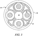
- the epicyclic gearbox 30 is shown by way of example in greater detail in Figure 3 .
- Each of the sun gear 28, planet gears 32 and ring gear 38 comprise teeth about their periphery to intermesh with the other gears. However, for clarity only exemplary portions of the teeth are illustrated in Figure 3 .
- Practical applications of a planetary epicyclic gearbox 30 generally comprise at least three planet gears 32.
- the epicyclic gearbox 30 illustrated by way of example in Figures 2 and 3 is of the planetary type, in that the planet carrier 34 is coupled to an output shaft via linkages 36, with the ring gear 38 fixed.
- the epicyclic gearbox 30 may be a star arrangement, in which the planet carrier 34 is held fixed, with the ring (or annulus) gear 38 allowed to rotate. In such an arrangement the fan 23 is driven by the ring gear 38.
- the gearbox 30 may be a differential gearbox in which the ring gear 38 and the planet carrier 34 are both allowed to rotate.
- any suitable arrangement may be used for locating the gearbox 30 in the engine 10 and/or for connecting the gearbox 30 to the engine 10.
- the connections (such as the linkages 36, 40 in the Figure 2 example) between the gearbox 30 and other parts of the engine 10 (such as the input shaft 26, the output shaft and the fixed structure 24) may have any desired degree of stiffness or flexibility.
- any suitable arrangement of the bearings between rotating and stationary parts of the engine may be used, and the disclosure is not limited to the exemplary arrangement of Figure 2 .
- the gearbox 30 has a star arrangement (described above)
- the skilled person would readily understand that the arrangement of output and support linkages and bearing locations would typically be different to that shown by way of example in Figure 2 .
- the present disclosure extends to a gas turbine engine having any arrangement of gearbox styles (for example star or planetary), support structures, input and output shaft arrangement, and bearing locations.
- gearbox styles for example star or planetary
- support structures for example star or planetary
- input and output shaft arrangement for example star or planetary
- bearing locations for example star or planetary
- the gearbox may drive additional and/or alternative components (e.g. the intermediate pressure compressor and/or a booster compressor).
- additional and/or alternative components e.g. the intermediate pressure compressor and/or a booster compressor.
- gas turbine engines to which the present disclosure may be applied may have alternative configurations.
- such engines may have an alternative number of compressors and/or turbines and/or an alternative number of interconnecting shafts.
- the gas turbine engine shown in Figure 1 has a split flow nozzle 18, 20 meaning that the flow through the bypass duct 22 has its own nozzle 18 that is separate to and radially outside the core exhaust nozzle 20.
- this is not limiting, and any aspect of the present disclosure may also apply to engines in which the flow through the bypass duct 22 and the flow through the core 11 are mixed, or combined, before (or upstream of) a single nozzle, which may be referred to as a mixed flow nozzle.
- One or both nozzles may have a fixed or variable area.
- the described example relates to a turbofan engine, the disclosure may apply, for example, to any type of gas turbine engine, such as an open rotor (in which the fan stage is not surrounded by a nacelle) or turboprop engine, for example.
- the geometry of the gas turbine engine 10, and components thereof, is defined by a conventional axis system, comprising an axial direction (which is aligned with the rotational axis 9), a radial direction (in the bottom-to-top direction in Figure 1 ), and a circumferential direction (perpendicular to the page in the Figure 1 view).
- the axial, radial and circumferential directions are mutually perpendicular.
- Figure 3 shows the epicyclic gear box components of a sun gear 28, a plurality of planet gears 32, a planet carrier 34 and a ring gear 38.
- a planet carrier that comprises a plurality of parts.
- the multiple parts need to be attached to each other and this increases the manufacturing cost and the attachment points are potential weakness in the planet carrier.
- Another known technique is to install the gears through the end of the planet carrier. However, this complicates the assembly process if it is difficult to access of the end of the planet carrier.
- Embodiments provide a new planet carrier 34 that allows an improved technique for assembling the planet carrier 34 with its gears.
- the planet carrier 34 may comprise a single piece carrier body.
- the structural integrity of the planet carrier 34 therefore has a good structural integrity even when the planet carrier 34 is made with a large diameter.
- the planet carrier 34 has an opening 41 in a wall of the carrier body.
- the opening 41 is large enough for all of the gears that are supported in the carrier body to be entirely passed through the opening 41.
- the shape of the opening 41 may be the same as, and slightly larger than, the outer profile of largest gear out of all of the planet gears 32 and sun gear 28 that are supported in the carrier body. That is to say, in a cross-section of the carrier body in a plane that is orthogonal to the longitudinal axis of the carrier body and at a longitudinal position along the carrier body that comprises the opening 41, the circumferential length of the opening 41 may be such that opening 41 is slightly larger than the largest diameter of gear required to pass through the opening 41; and the longitudinal length of the opening 41 may be slightly larger than the largest longitudinal length of gear required to pass through the opening 41.
- the carrier body has a good structural integrity because it is a solid and substantially annular structure along its length except for where the opening 41 is formed. That is to say, in a cross-section of the carrier body in a plane that is orthogonal to the longitudinal axis of the carrier body and at a longitudinal position along the carrier body that does not comprise the opening 41, the carrier body is substantially annular. Any reduction in structural integrity caused by forming the opening 41 in the wall of the carrier body may be minimised by the opening 41 not being substantially larger than what is required for all of the gears to be passed through the opening 41.
- Figure 4 shows a planet carrier 34 according to an example which does not fall within the scope of the appended clams as well as the insertion of gears into the carrier body of the planet carrier.
- the planet carrier 34 is being assembled with planet gears 32A, 32B and 32C and well as sun gear 28.
- planet gear 32A is first inserted into the planet carrier 34 through the opening 41 and moved to its intended position in the carrier body.
- Planet gear 32B is then inserted into the planet carrier 34 through the opening 41 and moved to its intended position in the carrier body.
- Sun gear 28 is then inserted into the planet carrier 34 through the opening 41 and moved to its intended position in the carrier body.
- planet gear 32C is inserted into the planet carrier 34 through the opening 41 and moved to its intended position in the carrier body.
- the gears may have any mesh arrangement.
- the mesh arrangement may be a double helix.
- the sun gear 28 may be a double helix with helixes the have opposite hands.
- a gear with such a mesh arrangement may be referred to as a herringbone gear.
- the side loading of the gears allows a sun gear 28 and planet gears 32 that are herringbone gears to be used.
- a sun gear 28 that is a herringbone gear it is not possible for a sun gear 28 that is a herringbone gear to be inserted into the planet carrier and for the sun gear 28 to be correctly meshed with the planet gears 32.
- the carrier body has gaps in its wall that are clearance holes for the planet gears 32.
- Each clearance hole through which part of a planet gear 32 protrudes is not large enough for the entire planet gear 32 to pass through.
- the opening 41 in the wall of the carrier body has the same location as the clearance hole of the planet gear 32C.
- Embodiments also include the opening 41 being separate from the clearance holes required for the planet gears 32.
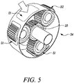
- Figure 5 shows a planet carrier 34 according to an embodiment of the invention as well as gears assembled with the planet carrier 34.
- the embodiment shown in Figure 5 shows a plurality of possible locations of the opening 41 in the wall of the carrier body.
- the opening 41 may be in a different location from the clearance holes through which parts of the planet gears 32 protrude.
- the opening 41 may alternatively be in the same location as a clearance holes through which parts of the planet gears 32 protrude.
- the planet carrier 34 may be designed with slightly larger spaces than necessary for supporting each of the planet gears 32. This would allow some axial and/or lateral movement of the planet gears 32 from their intended position in the planet carrier 34 prior to the planet gears 32 being located on their spindles. When inserting the planet gears 32 and sun gear 28 into the planet carrier 34 the additional possible movement of the gears may allow the gears to pass by each other without their teeth clashing and thereby ease the insertion of the gears into the planet carrier.
- the planet carrier may be assembled with four planet gears 32 and a sun gear 28 and have only one opening 41 with slightly larger spaces than necessary for supporting each of the planet gears 32 being provided.
- the planet carrier 34 comprises a plate 51 for covering the opening 41.
- the plate 51 may be attached to the carrier body after all of the gears have been inserted into the carrier body. When the plate 51 is attached the cover may entirely close the opening 41 so that the structural integrity of the planet carrier 34 is improved. When the opening 41 is arranged at the same location as a clearance hole, the plate 51 may only partially close the opening 41 so that the opening 41 is reduced to the size of a clearance hole.
- the plate 51 may be removable so that that the gears can be easily accessed for replacement, maintenance and inspection.
- the plate 51 may be bolted to the carrier body.
- the plate 51 may be attached to the carrier body by any other means. For example, the plate 51 may be welded to the carrier body.
- the plate 51 may be designed such that it has the same stiffness as the circumferential parts of the carrier body to the plate 51.
- each opening 41 may have its own plate 51 for entirely, or partially, covering the opening 41.
- Examples which do not fall within the scope of the appended claims also include plate 51 and/or carrier body comprising balancing lands that compensate for any deviations caused by forming the opening 41 in the wall of the carrier body.
- the opening 41 may alternative be considered to be a slot, such as a loading slot, or an access port.
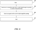
- Figure 6 is a flowchart of a process of assembling an epicyclic gearbox component according to an embodiment.
- step 601 the process begins.
- step 603 one or more planet gears are inserted into the carrier body through an opening 41 in the carrier body of a planet carrier 34.
- step 605 a sun gear 28 is inserted into the carrier body through the opening 41.
- step 607 the process ends.
- Embodiments include a number of modifications and variations to the techniques as described above.
- Some of the gears may be inserted into the planet carrier 34 through the opening 41 and the rest of the gears may be loaded axially.
- planet gear 32A may be first inserted into the planet carrier 34 through the opening 41 and moved to its intended position in the carrier body.
- Planet gear 32B may then be inserted into the planet carrier 34 through the opening 41 and moved to its intended position in the carrier body.
- Planet gear 32C may then be inserted into the planet carrier 34 through the opening 41 and moved to its intended position in the carrier body.
- the sun gear 28 may then be inserted axially into the planet carrier 34. It is possible to insert the sun gear 28 axially when the gears have a linear mesh.
Claims (14)
- Porte-satellites (34) pour une boîte de vitesses épicycloïdale (30), le porte-satellites (34) comprenant :un corps porteur monobloc agencé pour supporter une pluralité d'engrenages (28, 32) de la boîte de vitesses épicycloïdale (30) ; etune ouverture (41) dans une paroi du corps porteur ;dans lequel :dans une section transversale du corps porteur dans un plan orthogonal à l'axe longitudinal du corps porteur et à une position longitudinale le long du corps porteur qui ne comprend pas l'ouverture (41), le corps porteur est sensiblement annulaire ; etl'ouverture (41) est agencée de sorte que les engrenages (28, 32) que le corps porteur est agencé pour supporter puissent passer entièrement à travers l'ouverture (41) et caractérisé en ce que le porte-satellites comprend en outre une plaque de couverture (51) ;ladite plaque de couverture (51) pouvant être fixée au corps porteur ; etladite plaque de couverture (51) étant agencée pour fermer au moins partiellement l'ouverture (41) lorsqu'elle est fixée au corps porteur de sorte que les engrenages (28, 32) que le corps porteur est agencé pour supporter ne puissent pas passer entièrement à travers l'ouverture (41).
- Porte-satellites (34) selon la revendication 1, ladite plaque de couverture (51) étant agencée pour fermer entièrement l'ouverture (41) lorsqu'elle est fixée au corps porteur.
- Porte-satellites (34) selon la revendication 1 :ladite plaque de couverture (51) comprenant un trou ; etledit trou étant agencé de sorte qu'un engrenage puisse passer partiellement, mais pas entièrement, à travers le trou.
- Porte-satellites (34) selon l'une quelconque des revendications précédentes, dans une section transversale du corps porteur dans un plan orthogonal à l'axe longitudinal du corps porteur et à une position longitudinale le long du corps porteur qui comprend l'ouverture (41) :la longueur circonférentielle de l'ouverture (41) étant telle que l'ouverture (41) est légèrement plus grande que le plus grand diamètre d'engrenage requis pour passer à travers l'ouverture (41) ; etla longueur longitudinale de l'ouverture (41) étant légèrement plus grande à la plus grande longueur longitudinale d'engrenage requise pour passer à travers l'ouverture (41).
- Porte-satellites (34) selon l'une quelconque des revendications précédentes, dans lequel se trouvent une pluralité d'ouvertures (41) dans une paroi du corps porteur ; et
les ouvertures (41) sont agencées de sorte que les engrenages (28, 32) que le corps porteur est agencé pour supporter puissent passer entièrement à travers les ouvertures (41). - Composant de boîte de vitesses épicycloïdale comprenant :un porte-satellites (34) selon l'une quelconque des revendications précédentes ; etdes engrenages (28, 32) supportés par le corps porteur monobloc du porte-satellites ;lesdits engrenages (28, 32) comprenant un engrenage planétaire (28) et un ou plusieurs engrenages satellites (32).
- Composant de boîte de vitesses épicycloïdale selon la revendication 6, au moins l'engrenage planétaire étant un engrenage hélicoïdal double.
- Composant de boîte de vitesses épicycloïdale selon la revendication 6 ou 7, dans lequel se trouvent trois engrenages satellites (32) ou plus.
- Boîte de vitesses épicycloïdale (30) comprenant le composant de boîte de vitesses épicycloïdale selon l'une quelconque des revendications 6 à 8, ladite boîte de vitesses épicycloïdale (30) étant agencée dans une configuration en étoile, satellite ou différentielle.
- Moteur à turbine à gaz (10) pour un aéronef, le moteur à turbine à gaz comprenant :un noyau de moteur (11) comprenant une turbine (19), un compresseur (14) et un arbre de noyau (26) raccordant la turbine au compresseur ;une soufflante (23) située en amont du noyau de moteur, la soufflante comprenant une pluralité de pales de soufflante ; etune boîte de vitesses (30) qui reçoit une entrée de l'arbre de noyau (26) et délivre l'entraînement à la soufflante de manière à entraîner la soufflante à une vitesse de rotation inférieure à celle de l'arbre de noyau, ladite boîte de vitesses comprenant un composant de boîte de vitesses épicycloïdale selon l'une quelconque des revendications 6 à 8 et, éventuellement, ladite boîte de vitesses étant une boîte de vitesses épicycloïdale (30) selon la revendication 9.
- Moteur à turbine à gaz selon la revendication 10 :ladite turbine étant une première turbine (19), ledit compresseur étant un premier compresseur (14) et ledit arbre de noyau étant un premier arbre de noyau (26) ;ledit noyau de moteur comprenant en outre une seconde turbine (17), un second compresseur (15) et un second arbre de noyau (27) raccordant la seconde turbine au second compresseur ; etladite seconde turbine, ledit second compresseur et ledit second arbre de noyau étant agencés pour tourner à une vitesse de rotation plus élevée que celle du premier arbre de noyau.
- Procédé d'assemblage d'un composant de boîte de vitesses épicycloïdale selon l'une quelconque des revendications 6 à 8, le procédé comprenant :l'insertion d'un ou plusieurs engrenages satellites (32) dans le corps porteur à travers l'ouverture (41) ; etaprès l'insertion desdits un ou plusieurs engrenages satellites (32) dans le corps porteur, l'insertion de l'engrenage planétaire dans le corps porteur à travers l'ouverture (41).
- Procédé selon la revendication 12, comprenant en outre la fixation d'une plaque de couverture (51) au corps porteur de manière à recouvrir entièrement, ou partiellement, l'ouverture (41).
- Procédé selon la revendication 13 comprenant en outre :
après l'insertion de l'engrenage planétaire (28) dans le corps porteur et avant la fixation de la plaque de couverture (51) au corps porteur, l'insertion d'un ou plusieurs autres engrenages satellites (32) dans le corps porteur à travers l'ouverture (41).
Applications Claiming Priority (1)
| Application Number | Priority Date | Filing Date | Title |
|---|---|---|---|
| GBGB1820399.2A GB201820399D0 (en) | 2018-12-14 | 2018-12-14 | Planet carrier and method of assembling of a planet carrier |
Publications (2)
| Publication Number | Publication Date |
|---|---|
| EP3667048A1 EP3667048A1 (fr) | 2020-06-17 |
| EP3667048B1 true EP3667048B1 (fr) | 2022-06-15 |
Family
ID=65147346
Family Applications (1)
| Application Number | Title | Priority Date | Filing Date |
|---|---|---|---|
| EP19209735.0A Active EP3667048B1 (fr) | 2018-12-14 | 2019-11-18 | Support planétaire et procédé d'assemblage d'un support planétaire |
Country Status (4)
| Country | Link |
|---|---|
| US (1) | US10955045B2 (fr) |
| EP (1) | EP3667048B1 (fr) |
| CN (1) | CN111322157B (fr) |
| GB (1) | GB201820399D0 (fr) |
Families Citing this family (2)
| Publication number | Priority date | Publication date | Assignee | Title |
|---|---|---|---|---|
| EP3976996A1 (fr) * | 2019-06-22 | 2022-04-06 | Aerospace Transmission Technologies GmbH | Porte-satellite comportant une ouverture d'introduction en périphérie extérieure permettant l'introduction radiale d'un solaire et de satellites |
| KR102601751B1 (ko) | 2021-05-06 | 2023-11-14 | 현대모비스 주식회사 | 인휠 구동장치 및 인휠 구동장치의 조립방법 |
Family Cites Families (20)
| Publication number | Priority date | Publication date | Assignee | Title |
|---|---|---|---|---|
| US7448980B2 (en) * | 2005-05-09 | 2008-11-11 | Timken Us Corporation | Planetary gear assembly |
| US8667688B2 (en) * | 2006-07-05 | 2014-03-11 | United Technologies Corporation | Method of assembly for gas turbine fan drive gear system |
| US8205432B2 (en) * | 2007-10-03 | 2012-06-26 | United Technologies Corporation | Epicyclic gear train for turbo fan engine |
| US8313412B2 (en) * | 2009-02-05 | 2012-11-20 | Friede & Goldman, Ltd. | Gear assembly with asymmetric flex pin |
| JP4944165B2 (ja) * | 2009-06-26 | 2012-05-30 | 日立建機株式会社 | 減速装置 |
| JP4975081B2 (ja) | 2009-10-30 | 2012-07-11 | 川崎重工業株式会社 | 遊星歯車減速装置 |
| US8172717B2 (en) * | 2011-06-08 | 2012-05-08 | General Electric Company | Compliant carrier wall for improved gearbox load sharing |
| GB201210146D0 (en) * | 2012-06-08 | 2012-07-25 | Rolls Royce Plc | Oil scavenge arrangement |
| EP4223987A3 (fr) | 2013-08-21 | 2023-08-23 | Raytheon Technologies Corporation | Système d'engrenage à désalignement réduit |
| GB201417504D0 (en) * | 2014-10-03 | 2014-11-19 | Rolls Royce Deutschland | A gas turbine architecture |
| DE102015222611A1 (de) * | 2014-12-03 | 2016-06-09 | Schaeffler Technologies AG & Co. KG | Planetentrieb mit einem Planetenträger |
| WO2016146127A1 (fr) * | 2015-03-16 | 2016-09-22 | Vestas Wind Systems A/S | Turbine éolienne à système d'engrenage planétaire |
| AT517719B1 (de) * | 2015-09-15 | 2017-04-15 | Miba Gleitlager Austria Gmbh | Planetengetriebe für eine Windkraftanlage |
| EP3263952B1 (fr) | 2016-06-29 | 2019-11-27 | Rolls-Royce Deutschland Ltd & Co KG | Structure porteuse pour un entraînement par engrenage planétaire, ledit entraînement et turbomachine dotée de ce dernier |
| FR3054264B1 (fr) | 2016-07-25 | 2020-07-03 | Safran Aircraft Engines | Turbomachine a reducteur a train epicycloidal |
| CN206309922U (zh) * | 2016-08-30 | 2017-07-07 | 中车戚墅堰机车车辆工艺研究所有限公司 | 一种行星架以及包括其的行星齿轮箱 |
| GB201705979D0 (en) * | 2017-04-13 | 2017-05-31 | Rolls Royce Plc | A Gear, a method of manufacturing a gear and a geared gas turbine engine |
| US10669893B2 (en) * | 2017-05-25 | 2020-06-02 | General Electric Company | Air bearing and thermal management nozzle arrangement for interdigitated turbine engine |
| CN108167424A (zh) | 2017-12-13 | 2018-06-15 | 舍弗勒技术股份两合公司 | 集成有驻车齿的行星架及行星齿轮机构 |
| FR3080551B1 (fr) * | 2018-04-26 | 2022-01-21 | Safran Trans Systems | Procede d'assemblage pour un train d'engrenages epicycloidal ou planetaire |
-
2018
- 2018-12-14 GB GBGB1820399.2A patent/GB201820399D0/en not_active Ceased
-
2019
- 2019-11-18 EP EP19209735.0A patent/EP3667048B1/fr active Active
- 2019-11-27 CN CN201911185276.0A patent/CN111322157B/zh active Active
- 2019-12-04 US US16/702,716 patent/US10955045B2/en active Active
Also Published As
| Publication number | Publication date |
|---|---|
| US20200191257A1 (en) | 2020-06-18 |
| CN111322157B (zh) | 2023-10-31 |
| EP3667048A1 (fr) | 2020-06-17 |
| CN111322157A (zh) | 2020-06-23 |
| GB201820399D0 (en) | 2019-01-30 |
| US10955045B2 (en) | 2021-03-23 |
Similar Documents
| Publication | Publication Date | Title |
|---|---|---|
| EP3587749B1 (fr) | Moteur de turbine à gaz | |
| EP3553303A1 (fr) | Moteur à turbine à gaz et agencement de turbine | |
| EP3611398B1 (fr) | Système de palier de stabilisation pour moteurs à double flux à engrenage | |
| EP3885552A1 (fr) | Moteur de turbine à gaz | |
| US11584532B2 (en) | Gas turbine engine compression system with core compressor pressure ratio | |
| EP3667048B1 (fr) | Support planétaire et procédé d'assemblage d'un support planétaire | |
| EP3800378B1 (fr) | Élément de raidissement pour ensemble boîtier d'un système d'engrenage épicycloïdal | |
| US10677169B1 (en) | Fan blade retention assembly | |
| US20190293170A1 (en) | Method for assembling a planetary gearbox, a planetary carrier and an aircraft engine | |
| EP3594447A1 (fr) | Aubes de redresseur de moteur de turbine à gaz | |
| US11879397B2 (en) | Gas turbine engine with staggered epicyclic gearbox | |
| EP3594476B1 (fr) | Agencement de montage de moteur à turbine à gaz à turbosoufflante à engrenage | |
| EP3591206A1 (fr) | Exploitabilité de moteur d'aéronef | |
| EP3546367B1 (fr) | Agencement de montage de moteur à double flux à engrenage | |
| US11834958B2 (en) | Rotor assembly | |
| US11313236B2 (en) | Coolant channel | |
| EP3712409A1 (fr) | Support pour moteur de turbine à gaz | |
| US10968835B2 (en) | Apparatus for gas turbine engines | |
| US11199196B2 (en) | Geared turbofan engine | |
| EP4001594A1 (fr) | Ensemble support pour moteur à turbine à gaz | |
| EP3819480A1 (fr) | Support | |
| EP3617557A1 (fr) | Système de distribution d'huile auxiliaire et moteur à turbine à gaz comportant un système de distribution d'huile auxiliaire | |
| GB2588825A (en) | Method and assembly for securing payloads |
Legal Events
| Date | Code | Title | Description |
|---|---|---|---|
| PUAI | Public reference made under article 153(3) epc to a published international application that has entered the european phase |
Free format text: ORIGINAL CODE: 0009012 |
|
| STAA | Information on the status of an ep patent application or granted ep patent |
Free format text: STATUS: THE APPLICATION HAS BEEN PUBLISHED |
|
| AK | Designated contracting states |
Kind code of ref document: A1 Designated state(s): AL AT BE BG CH CY CZ DE DK EE ES FI FR GB GR HR HU IE IS IT LI LT LU LV MC MK MT NL NO PL PT RO RS SE SI SK SM TR |
|
| AX | Request for extension of the european patent |
Extension state: BA ME |
|
| STAA | Information on the status of an ep patent application or granted ep patent |
Free format text: STATUS: REQUEST FOR EXAMINATION WAS MADE |
|
| 17P | Request for examination filed |
Effective date: 20201216 |
|
| RBV | Designated contracting states (corrected) |
Designated state(s): AL AT BE BG CH CY CZ DE DK EE ES FI FR GB GR HR HU IE IS IT LI LT LU LV MC MK MT NL NO PL PT RO RS SE SI SK SM TR |
|
| GRAP | Despatch of communication of intention to grant a patent |
Free format text: ORIGINAL CODE: EPIDOSNIGR1 |
|
| STAA | Information on the status of an ep patent application or granted ep patent |
Free format text: STATUS: GRANT OF PATENT IS INTENDED |
|
| INTG | Intention to grant announced |
Effective date: 20211122 |
|
| GRAJ | Information related to disapproval of communication of intention to grant by the applicant or resumption of examination proceedings by the epo deleted |
Free format text: ORIGINAL CODE: EPIDOSDIGR1 |
|
| STAA | Information on the status of an ep patent application or granted ep patent |
Free format text: STATUS: REQUEST FOR EXAMINATION WAS MADE |
|
| INTC | Intention to grant announced (deleted) | ||
| GRAP | Despatch of communication of intention to grant a patent |
Free format text: ORIGINAL CODE: EPIDOSNIGR1 |
|
| STAA | Information on the status of an ep patent application or granted ep patent |
Free format text: STATUS: GRANT OF PATENT IS INTENDED |
|
| INTG | Intention to grant announced |
Effective date: 20220405 |
|
| RIN1 | Information on inventor provided before grant (corrected) |
Inventor name: HARVEY, GILES |
|
| GRAS | Grant fee paid |
Free format text: ORIGINAL CODE: EPIDOSNIGR3 |
|
| GRAA | (expected) grant |
Free format text: ORIGINAL CODE: 0009210 |
|
| STAA | Information on the status of an ep patent application or granted ep patent |
Free format text: STATUS: THE PATENT HAS BEEN GRANTED |
|
| AK | Designated contracting states |
Kind code of ref document: B1 Designated state(s): AL AT BE BG CH CY CZ DE DK EE ES FI FR GB GR HR HU IE IS IT LI LT LU LV MC MK MT NL NO PL PT RO RS SE SI SK SM TR |
|
| REG | Reference to a national code |
Ref country code: CH Ref legal event code: EP Ref country code: GB Ref legal event code: FG4D |
|
| REG | Reference to a national code |
Ref country code: IE Ref legal event code: FG4D |
|
| REG | Reference to a national code |
Ref country code: DE Ref legal event code: R096 Ref document number: 602019015863 Country of ref document: DE |
|
| REG | Reference to a national code |
Ref country code: AT Ref legal event code: REF Ref document number: 1498526 Country of ref document: AT Kind code of ref document: T Effective date: 20220715 |
|
| REG | Reference to a national code |
Ref country code: LT Ref legal event code: MG9D |
|
| REG | Reference to a national code |
Ref country code: NL Ref legal event code: MP Effective date: 20220615 |
|
| PG25 | Lapsed in a contracting state [announced via postgrant information from national office to epo] |
Ref country code: SE Free format text: LAPSE BECAUSE OF FAILURE TO SUBMIT A TRANSLATION OF THE DESCRIPTION OR TO PAY THE FEE WITHIN THE PRESCRIBED TIME-LIMIT Effective date: 20220615 Ref country code: NO Free format text: LAPSE BECAUSE OF FAILURE TO SUBMIT A TRANSLATION OF THE DESCRIPTION OR TO PAY THE FEE WITHIN THE PRESCRIBED TIME-LIMIT Effective date: 20220915 Ref country code: LT Free format text: LAPSE BECAUSE OF FAILURE TO SUBMIT A TRANSLATION OF THE DESCRIPTION OR TO PAY THE FEE WITHIN THE PRESCRIBED TIME-LIMIT Effective date: 20220615 Ref country code: HR Free format text: LAPSE BECAUSE OF FAILURE TO SUBMIT A TRANSLATION OF THE DESCRIPTION OR TO PAY THE FEE WITHIN THE PRESCRIBED TIME-LIMIT Effective date: 20220615 Ref country code: GR Free format text: LAPSE BECAUSE OF FAILURE TO SUBMIT A TRANSLATION OF THE DESCRIPTION OR TO PAY THE FEE WITHIN THE PRESCRIBED TIME-LIMIT Effective date: 20220916 Ref country code: FI Free format text: LAPSE BECAUSE OF FAILURE TO SUBMIT A TRANSLATION OF THE DESCRIPTION OR TO PAY THE FEE WITHIN THE PRESCRIBED TIME-LIMIT Effective date: 20220615 Ref country code: BG Free format text: LAPSE BECAUSE OF FAILURE TO SUBMIT A TRANSLATION OF THE DESCRIPTION OR TO PAY THE FEE WITHIN THE PRESCRIBED TIME-LIMIT Effective date: 20220915 |
|
| REG | Reference to a national code |
Ref country code: AT Ref legal event code: MK05 Ref document number: 1498526 Country of ref document: AT Kind code of ref document: T Effective date: 20220615 |
|
| PG25 | Lapsed in a contracting state [announced via postgrant information from national office to epo] |
Ref country code: RS Free format text: LAPSE BECAUSE OF FAILURE TO SUBMIT A TRANSLATION OF THE DESCRIPTION OR TO PAY THE FEE WITHIN THE PRESCRIBED TIME-LIMIT Effective date: 20220615 Ref country code: LV Free format text: LAPSE BECAUSE OF FAILURE TO SUBMIT A TRANSLATION OF THE DESCRIPTION OR TO PAY THE FEE WITHIN THE PRESCRIBED TIME-LIMIT Effective date: 20220615 |
|
| PG25 | Lapsed in a contracting state [announced via postgrant information from national office to epo] |
Ref country code: NL Free format text: LAPSE BECAUSE OF FAILURE TO SUBMIT A TRANSLATION OF THE DESCRIPTION OR TO PAY THE FEE WITHIN THE PRESCRIBED TIME-LIMIT Effective date: 20220615 |
|
| PG25 | Lapsed in a contracting state [announced via postgrant information from national office to epo] |
Ref country code: SM Free format text: LAPSE BECAUSE OF FAILURE TO SUBMIT A TRANSLATION OF THE DESCRIPTION OR TO PAY THE FEE WITHIN THE PRESCRIBED TIME-LIMIT Effective date: 20220615 Ref country code: SK Free format text: LAPSE BECAUSE OF FAILURE TO SUBMIT A TRANSLATION OF THE DESCRIPTION OR TO PAY THE FEE WITHIN THE PRESCRIBED TIME-LIMIT Effective date: 20220615 Ref country code: RO Free format text: LAPSE BECAUSE OF FAILURE TO SUBMIT A TRANSLATION OF THE DESCRIPTION OR TO PAY THE FEE WITHIN THE PRESCRIBED TIME-LIMIT Effective date: 20220615 Ref country code: PT Free format text: LAPSE BECAUSE OF FAILURE TO SUBMIT A TRANSLATION OF THE DESCRIPTION OR TO PAY THE FEE WITHIN THE PRESCRIBED TIME-LIMIT Effective date: 20221017 Ref country code: ES Free format text: LAPSE BECAUSE OF FAILURE TO SUBMIT A TRANSLATION OF THE DESCRIPTION OR TO PAY THE FEE WITHIN THE PRESCRIBED TIME-LIMIT Effective date: 20220615 Ref country code: EE Free format text: LAPSE BECAUSE OF FAILURE TO SUBMIT A TRANSLATION OF THE DESCRIPTION OR TO PAY THE FEE WITHIN THE PRESCRIBED TIME-LIMIT Effective date: 20220615 Ref country code: CZ Free format text: LAPSE BECAUSE OF FAILURE TO SUBMIT A TRANSLATION OF THE DESCRIPTION OR TO PAY THE FEE WITHIN THE PRESCRIBED TIME-LIMIT Effective date: 20220615 Ref country code: AT Free format text: LAPSE BECAUSE OF FAILURE TO SUBMIT A TRANSLATION OF THE DESCRIPTION OR TO PAY THE FEE WITHIN THE PRESCRIBED TIME-LIMIT Effective date: 20220615 |
|
| PG25 | Lapsed in a contracting state [announced via postgrant information from national office to epo] |
Ref country code: PL Free format text: LAPSE BECAUSE OF FAILURE TO SUBMIT A TRANSLATION OF THE DESCRIPTION OR TO PAY THE FEE WITHIN THE PRESCRIBED TIME-LIMIT Effective date: 20220615 Ref country code: IS Free format text: LAPSE BECAUSE OF FAILURE TO SUBMIT A TRANSLATION OF THE DESCRIPTION OR TO PAY THE FEE WITHIN THE PRESCRIBED TIME-LIMIT Effective date: 20221015 |
|
| REG | Reference to a national code |
Ref country code: DE Ref legal event code: R097 Ref document number: 602019015863 Country of ref document: DE |
|
| PG25 | Lapsed in a contracting state [announced via postgrant information from national office to epo] |
Ref country code: AL Free format text: LAPSE BECAUSE OF FAILURE TO SUBMIT A TRANSLATION OF THE DESCRIPTION OR TO PAY THE FEE WITHIN THE PRESCRIBED TIME-LIMIT Effective date: 20220615 |
|
| PLBE | No opposition filed within time limit |
Free format text: ORIGINAL CODE: 0009261 |
|
| STAA | Information on the status of an ep patent application or granted ep patent |
Free format text: STATUS: NO OPPOSITION FILED WITHIN TIME LIMIT |
|
| PG25 | Lapsed in a contracting state [announced via postgrant information from national office to epo] |
Ref country code: DK Free format text: LAPSE BECAUSE OF FAILURE TO SUBMIT A TRANSLATION OF THE DESCRIPTION OR TO PAY THE FEE WITHIN THE PRESCRIBED TIME-LIMIT Effective date: 20220615 |
|
| 26N | No opposition filed |
Effective date: 20230316 |
|
| PG25 | Lapsed in a contracting state [announced via postgrant information from national office to epo] |
Ref country code: SI Free format text: LAPSE BECAUSE OF FAILURE TO SUBMIT A TRANSLATION OF THE DESCRIPTION OR TO PAY THE FEE WITHIN THE PRESCRIBED TIME-LIMIT Effective date: 20220615 |
|
| PG25 | Lapsed in a contracting state [announced via postgrant information from national office to epo] |
Ref country code: MC Free format text: LAPSE BECAUSE OF FAILURE TO SUBMIT A TRANSLATION OF THE DESCRIPTION OR TO PAY THE FEE WITHIN THE PRESCRIBED TIME-LIMIT Effective date: 20220615 |
|
| REG | Reference to a national code |
Ref country code: CH Ref legal event code: PL |
|
| P01 | Opt-out of the competence of the unified patent court (upc) registered |
Effective date: 20230528 |
|
| REG | Reference to a national code |
Ref country code: BE Ref legal event code: MM Effective date: 20221130 |
|
| PG25 | Lapsed in a contracting state [announced via postgrant information from national office to epo] |
Ref country code: LI Free format text: LAPSE BECAUSE OF NON-PAYMENT OF DUE FEES Effective date: 20221130 Ref country code: CH Free format text: LAPSE BECAUSE OF NON-PAYMENT OF DUE FEES Effective date: 20221130 |
|
| PG25 | Lapsed in a contracting state [announced via postgrant information from national office to epo] |
Ref country code: LU Free format text: LAPSE BECAUSE OF NON-PAYMENT OF DUE FEES Effective date: 20221118 |
|
| PG25 | Lapsed in a contracting state [announced via postgrant information from national office to epo] |
Ref country code: IE Free format text: LAPSE BECAUSE OF NON-PAYMENT OF DUE FEES Effective date: 20221118 |
|
| PG25 | Lapsed in a contracting state [announced via postgrant information from national office to epo] |
Ref country code: BE Free format text: LAPSE BECAUSE OF NON-PAYMENT OF DUE FEES Effective date: 20221130 |
|
| PGFP | Annual fee paid to national office [announced via postgrant information from national office to epo] |
Ref country code: GB Payment date: 20231121 Year of fee payment: 5 |
|
| PG25 | Lapsed in a contracting state [announced via postgrant information from national office to epo] |
Ref country code: IT Free format text: LAPSE BECAUSE OF FAILURE TO SUBMIT A TRANSLATION OF THE DESCRIPTION OR TO PAY THE FEE WITHIN THE PRESCRIBED TIME-LIMIT Effective date: 20220615 |
|
| PGFP | Annual fee paid to national office [announced via postgrant information from national office to epo] |
Ref country code: FR Payment date: 20231123 Year of fee payment: 5 Ref country code: DE Payment date: 20231127 Year of fee payment: 5 |
|
| PG25 | Lapsed in a contracting state [announced via postgrant information from national office to epo] |
Ref country code: HU Free format text: LAPSE BECAUSE OF FAILURE TO SUBMIT A TRANSLATION OF THE DESCRIPTION OR TO PAY THE FEE WITHIN THE PRESCRIBED TIME-LIMIT; INVALID AB INITIO Effective date: 20191118 |