EP3666417A1 - Roller assembly, casting apparatus and roller separating method therefor - Google Patents
Roller assembly, casting apparatus and roller separating method therefor Download PDFInfo
- Publication number
- EP3666417A1 EP3666417A1 EP18843075.5A EP18843075A EP3666417A1 EP 3666417 A1 EP3666417 A1 EP 3666417A1 EP 18843075 A EP18843075 A EP 18843075A EP 3666417 A1 EP3666417 A1 EP 3666417A1
- Authority
- EP
- European Patent Office
- Prior art keywords
- roller
- slab
- movement path
- attached
- fixed shaft
- Prior art date
- Legal status (The legal status is an assumption and is not a legal conclusion. Google has not performed a legal analysis and makes no representation as to the accuracy of the status listed.)
- Granted
Links
Images

Classifications
-
- B—PERFORMING OPERATIONS; TRANSPORTING
- B22—CASTING; POWDER METALLURGY
- B22D—CASTING OF METALS; CASTING OF OTHER SUBSTANCES BY THE SAME PROCESSES OR DEVICES
- B22D11/00—Continuous casting of metals, i.e. casting in indefinite lengths
- B22D11/12—Accessories for subsequent treating or working cast stock in situ
- B22D11/128—Accessories for subsequent treating or working cast stock in situ for removing
- B22D11/1287—Rolls; Lubricating, cooling or heating rolls while in use
-
- B—PERFORMING OPERATIONS; TRANSPORTING
- B22—CASTING; POWDER METALLURGY
- B22D—CASTING OF METALS; CASTING OF OTHER SUBSTANCES BY THE SAME PROCESSES OR DEVICES
- B22D11/00—Continuous casting of metals, i.e. casting in indefinite lengths
- B22D11/12—Accessories for subsequent treating or working cast stock in situ
- B22D11/128—Accessories for subsequent treating or working cast stock in situ for removing
-
- B—PERFORMING OPERATIONS; TRANSPORTING
- B22—CASTING; POWDER METALLURGY
- B22D—CASTING OF METALS; CASTING OF OTHER SUBSTANCES BY THE SAME PROCESSES OR DEVICES
- B22D11/00—Continuous casting of metals, i.e. casting in indefinite lengths
- B22D11/12—Accessories for subsequent treating or working cast stock in situ
- B22D11/128—Accessories for subsequent treating or working cast stock in situ for removing
- B22D11/1282—Vertical casting and curving the cast stock to the horizontal
-
- B—PERFORMING OPERATIONS; TRANSPORTING
- B22—CASTING; POWDER METALLURGY
- B22D—CASTING OF METALS; CASTING OF OTHER SUBSTANCES BY THE SAME PROCESSES OR DEVICES
- B22D11/00—Continuous casting of metals, i.e. casting in indefinite lengths
- B22D11/12—Accessories for subsequent treating or working cast stock in situ
- B22D11/128—Accessories for subsequent treating or working cast stock in situ for removing
- B22D11/1285—Segment changing devices for supporting or guiding frames
-
- B—PERFORMING OPERATIONS; TRANSPORTING
- B22—CASTING; POWDER METALLURGY
- B22D—CASTING OF METALS; CASTING OF OTHER SUBSTANCES BY THE SAME PROCESSES OR DEVICES
- B22D11/00—Continuous casting of metals, i.e. casting in indefinite lengths
- B22D11/16—Controlling or regulating processes or operations
- B22D11/20—Controlling or regulating processes or operations for removing cast stock
- B22D11/208—Controlling or regulating processes or operations for removing cast stock for aligning the guide rolls
Definitions
- the present disclosure relates to a roller assembly, a casting apparatus, and a roller separating method for the same, and more particularly, to a roller assembly in which rollers are retreatable from the movement path of a to-be-treated material, a casting apparatus in which a roller fused to a slab on the movement path is separable during emergency, and a roller separating method for the casting apparatus.
- Continuous casting equipment is the equipment for producing slabs using molten steel, and is configured by a turndish for storing a molten steel, a mold for receiving the molten steel in the turndish and firstly solidifying the molten steel into a slab form; and segments for drawing the slab from the mold and secondly cooling the slab. At this point, the segments are consecutively arranged under the mold along the movement path of the slab.
- Segments of related arts each include: a plurality of guide rolls which are consecutively arranged under the mold and rolls the slab while guiding the slab; a plurality of roller assemblies which rotatably support both end sections of the guide rolls; an upper frame and a lower frame which are continuously arranged under the mold, are spaced apart from each other so as to face each other with the movement path of the slab therebetween; a plurality of tie rods for connecting the upper and lower frames spaced part from each other and facing each other; and a hydraulic cylinder which is capable of adjusting the gap between the upper and lower frames spaced part from each other and facing each other.
- the segments having the hydraulic cylinder according to related arts are frequently damaged due to high-temperature and high-humidity operation environments and high ferro-static pressure inside the slab.
- the mainly damaged portion is the hydraulic cylinder portion, and recently, a structure in which the hydraulic cylinder is removed and roll gaps are fixed has been mainly used.
- Patent document 1 KR10-2017-0065963 A
- the present disclosure provides a roller assembly capable of causing a roller to retreat from the movement path of a to-be-treated material
- the present disclosure also provides a casting device capable of separating a roller fused to a slab in a movement path during emergency.
- the present disclosure also provides a roller separating method capable of separating a roller fused to a slab in a movement path during emergency.
- the plunger may be formed such that at least a portion thereof, while retreating by means of a hydraulic pressure, causes the fixed shaft to retreat from the movement path.
- the plunger may be attached to pass through a rear surface of the body and be connected to a rear end of the fixed shaft.
- the plunger may include: a hollow outer cylinder having a front end attached to the rear surface of the body, and an inner stepped portion formed on an inner circumferential surface thereof, the inner diameter of a rear end thereof from the inner stepped portion being larger than the inner diameter of a front end thereof; an inner cylinder attached to pass through the outer cylinder and having an outer stepped portion on an outer circumferential surface thereof, the outer circumferential surface thereof being in contact with the inner circumferential surface of the outer cylinder, a connecting shaft formed to protrude from a front end of the inner cylinder, passing through the rear surface of the body, and connected to a rear end of the fixed shaft; and an injection port attached to pass through the outer cylinder so as to form a hydraulic pressure by injecting a fluid into a hydraulic pressure space formed by the inner stepped portion and the outer stepped portion.
- the plunger may further include an injection port valve attached to the injection port and opened in an intermittent manner.
- a casting apparatus for casting a slab using a mold includes a plurality of segments consecutively arranged under the mold so as to guide a movement of the slab drawn from the mold, and the segments comprises: a plurality of rollers consecutively arranged along a movement path and spaced apart from each other so as to face each other with the movement path of the slab therebetween; and a plurality of roller assemblies attached to the plurality of rollers and having at least a portion capable of advancing and retreating with respect to the movement path.
- the segments may include a first frame and a second frame spaced apart from each other so as to face each other with the movement path therebetween, the first frame and the second frame support the plurality of roller assemblies, and the roller assemblies may be formed such that at least a portion thereof may cause the rollers to retreat from the movement path while retreating by means of hydraulic pressure.
- the roller assemblies may each include: a supporter configured to rotatably support the roller; a fixed shaft attached to a rear surface of the supporter and having at least a stretchable portion; a body attached to the rear surface side of the supporter so as to surround the fixed shaft; and a plunger attached so as to pass through a rear surface of the body, connected to a rear end of the fixed shaft, and formed so that at least a portion thereof advances and retreats with respect to the movement path by means of hydraulic pressure.
- a roller separating method for separating a roller from a slab in a movement path includes: drawing the slab from a mold; guiding a movement of the slab drawn from the mold using a plurality of segments consecutively arranged along the movement path; and causing a plurality of roller assemblies, which are attached to a plurality of rollers provided to the segments, and have at least a portion formed so as to advance and retreat with respect to the movement path of the slab, to retreat from the movement path and causing the rollers supported by the roller assemblies to be spaced apart from the slab when the slab is being moved or stops.
- the causing the rollers to be spaced apart from the slab may include: applying a hydraulic pressure into the roller assemblies and causing a portion of the roller assemblies to retreat from the movement path; and causing the rollers connected to the portion of the roller assemblies to retreat from the movement path.
- the causing the rollers to retreat from the slab to be spaced apart from the slab may further include applying the hydraulic pressure in an intermittent manner when applying the hydraulic pressure to the roller assemblies.
- a plurality of rollers, consecutively arranged along the movement path of a to-be-treated material can easily be caused to retreat from the movement path of the to-be-treated material by using a plunger structure provided so as to easily cause only a portion of an apparatus to retreat.
- roller assemblies of segments are configured as roller assemblies to which the plunger structures are applied, and when a roller is fused to a slab due to outflow of a molten steel, retention of slabs, or the like, hydraulic pressure is formed inside the corresponding roller assembly using the plunger structure, and a fixed shaft of each of the roller assembly can be caused to retreat from the movement path of a slab, and the roller supported by the fixed shaft can easily be separated from the slab.
- a roller can forcibly be spaced apart from a slab by applying a hydraulic pressure to the plunger of a roller assembly, and thus, slabs and the continuous casting equipment can be easily and quickly separated, and the time and man power required to recover the equipment can remarkably be reduced.
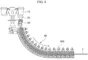
- FIG. 1 is a schematic view of a casting apparatus in accordance with an exemplary embodiment.
- a casting apparatus in accordance with an exemplary embodiment is a casting apparatus that casts a to-be-treated material such as a slab 1 by using a mold 30 and includes a plurality of segments 500 consecutively arranged under the mold 30 so as to guide the movement of the slab 1 drawn from the mold 30.
- the segments 500 may be consecutively arranged in a predetermined direction so as to form a movement path 40 of the slab 1 under the mold 30. That is, the segments 500 may each be installed under the mold 30 and form the movement path 40 of the slab 1.
- the shape and the type of the movement path 40 may be diversified.
- the movement path 40 may be curved or vertically curved, or may be vertical.
- the movement path 40 of the slab 1 may be referred to as a cooling line
- the plurality of segments 500 may be referred to as a cooling platform.
- Each of the segments 500 may be provided with a plurality of rollers and a coolant nozzle (not shown). Each of the segments 500 may reduce and shape the slab 1 while guiding the slab 1, which is drawn from the mold 30 roll, using the plurality of rollers, and may solidify and cool the slab 1 while spraying a coolant such as cooling water to the slab 1 using the plurality of coolant nozzles.
- the casting apparatus in accordance with an exemplary embodiment may further include: a ladle 10 for transporting a molten material, such as a molten steel; a turndish 20 for receiving the molten steel from the ladle 10 and temporarily storing the molten steel; and a mold 30 for receiving the molten steel from the turndish 20 and solidifying the molten steel into a slab form.
- a ladle 10 for transporting a molten material, such as a molten steel
- a turndish 20 for receiving the molten steel from the ladle 10 and temporarily storing the molten steel
- a mold 30 for receiving the molten steel from the turndish 20 and solidifying the molten steel into a slab form.
- the ladle 10, the turndish 20, and the mold 30 described above may have various configurations and types, and are not particularly limited in the exemplary embodiments. In order not to obscure the subject matters of the present disclosure, detailed description thereon will not be provided.
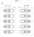
- FIG. 2 is a schematic view of segments according to an exemplary embodiment. Referring to FIG. 2 , segments in accordance with an exemplary embodiment will be described.
- Segments 500 in accordance with an exemplary embodiment include: a plurality of rollers 510 which are consecutively arranged along a movement path 40 so as to be spaced apart from each other and face each other with the movement path 40 of a slab 1 therebetween; and a plurality of roller assemblies 520 which are attached to the plurality of rollers 510 and formed so that at least a portion thereof advances and retreats with respect to the movement path 40.
- the segments 500 may further include a first frame 530a and a second frame 530b which are spaced apart from each other so as to face each other with the movement path 40 therebetween and support the plurality of roller assemblies 520.
- the plurality of rollers 510 may be consecutively arranged in a direction, in which the movement path extends, at positions spaced apart from each other in a front-rear direction.
- the front-rear direction may be the direction in which the first frame 530a and the second frame 530b are spaced apart from each other when viewed in FIG. 2 .
- the plurality of rollers 510 may also be consecutively arranged in the direction in which the movement path extends at the position spaced apart from each other in the vertical direction.
- the first frame 530a and the second frame 530b may be arranged so as to be spaced apart from each other in the vertical direction. That is, the plurality of rollers 510, the first frame 530a and the second frame 530b may be variously arranged in the direction in which the movement path extends.
- the plurality of rollers 510 may respectively extend in the left-right direction.
- the left-right direction may be a direction crossing the above-described front-rear direction and vertical direction, in other words, a direction crossing the movement path.
- the first frame 530a and the second frame 530b are main bodies of the segments 500, and as illustrated in FIG. 2 , may be spaced apart from each other in the front-rear direction.
- the first frame 530a and the second frame 530b may also be spaced apart from each other in the vertical direction.
- the first frame 530a and the second frame 530b may be fixedly installed at the respective positions thereof, and may be fixed so that the gap therebetween is a predetermined distance.
- the plurality of rollers 510 are respectively disposed on the mutually facing surfaces of the first frame 530a and the second frame 530b, and the slab may be introduced between the first frame 530a and the second frame 530b and move while supported by the plurality of rollers 510.
- the plurality of rollers 510 may be installed so as to be axially rotatable around respective left-right direction shafts (not shown), and to this end, the plurality of roller assemblies 520 may be installed on both left-right direction ends of the respective plurality of rollers 510.
- the plurality of roller assemblies 520 may support the respective rollers 510 thereof in an axially rotatable manner in the left-right direction.
- the plurality of roller assemblies 520 may be spaced apart from each other in the front-rear direction and spaced apart from each other with the plurality of rollers 510 therebetween, and may be attached, in the front-rear direction, to the end sections of the respective rollers 510 so as to connect the rollers 510 on the first frame 530a side among the plurality of rollers 510 to the first frame 530a, and to connect the rollers 510 on the second frame 530b side among the plurality of rollers 510 to the second frame 530b.
- the segments 500 having the above-described structure may be referred to as fixed roll gap-type segments.
- segments (not shown) in accordance with a comparative example are configured in a structure in which a first frame and a second frame are installed to be mutually connected by a tie rod, and the gap between the first frame and the second frame is adjusted by a hydraulic cylinder.
- the segments in accordance with the comparative example are referred to as segments having a hydraulic cylinder-type roll gap adjustment device, or variable roll gap-type segments.
- the segments 500 in accordance with an exemplary embodiment have a merit of easy inspection, maintenance, and repair of equipment than the segments in accordance with the comparative example.
- the segments in accordance with the comparative example is not easily operated and handled due to the tie rod weak against damage in high-temperature, high-humidity environment and the hydraulic cylinder, but the segments 500 in accordance with an exemplary embodiment has the first frame 530a and the second frame 530b fixedly installed to a predetermined positions, and thus may be relatively easy to operate and handle.
- the rollers 510 may be fused to the slab, but at this point, the rollers 520 may be forcibly removed from the slab and separated from the slab by using the roller assemblies in accordance with an exemplary embodiment.
- a hydraulic pressure is injected into, for example, a later-described plunger 524 of the roller assembly 520, so that the fixed shaft 522 of the roller assembly 520 may be caused to retreat and the roller 510 connected to the fixed shaft 522 may be caused to retreat.
- the separation of the roller 510 and the slab may be simply carried out.
- the segments 500 in accordance with an exemplary embodiment are fixed roll gap-type segments having a fixed distance between the first frame 530a and the second frame 530b, have a strong structure, and are easily handled, and even in an emergent situation, the slab and the casting apparatus may be easily separated in order to recover the casting apparatus. Specifically, in an emergent situation, the slab and rollers may be easily separated using the roller assemblies 520.
- FIG. 3 is a schematic view of a roller assembly according to an exemplary embodiment
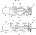
- FIG. 4 is an operational view of a roller assembly according to an exemplary embodiment.
- (a) of FIG. 4 is an operational view of a roller assembly illustrating a state in which a roller in a movement path is supported during a normal operation
- (b) of FIG. 4 is an operational view of the roller assembly illustrating a state in which the roller retreats from the movement path by the roller assembly during emergency.
- a roller assembly 520 in accordance with an exemplary embodiment may be used not only as a supporting and retreating device for the roller of the segment 500 in a casting apparatus, but also used as a supporting and retreating device for the roller which is installed in the movement path of equipment for various to-be-treated materials and guides the movement of the to-be-treated material.
- the roller assembly 520 in accordance with an exemplary embodiment is a roller assembly 520 which is capable of causing a roller 510, arranged in the movement path of a to-be-treated material such as a slab, to retreat from the movement path of the slab, the roller assembly including: a supporter 521 that supports the roller 510 in an axially rotatable manner; a fixed shaft 522 attached to the rear surface of the supporter 521 and having at least a stretchable portion; and a body 523 attached to the rear surface side of the supporter 521 so as to surround the fixed shaft 522 and fixed to a predetermined frame which is installed to surround the movement path of the slab; and a plunger 524 attached to pass through the rear surface of the body 523 and connected to the rear end of the fixed shaft 522.
- the plunger 524 may be formed so that at least a portion thereof may advance and retreat by using a hydraulic pressure with respect to the movement path of the slab, and the fixed shaft 522 may cause the roller 510 to retreat from the movement path of the slab while retreating by the plunger 524.
- the roller 510 when casting a thick slab, and when various emergent situations occur, the roller 510 may be forcibly spaced apart from the slab, so that the subsequent repair and recovery may be easy.
- extension direction of the movement path and the arrangement direction of the rollers may be variously different from the installation direction and the extension direction of components of the roller assembly 520.
- the supporter 521 may support the roller 510 disposed in the movement path of the slab in an axially rotatable manner.
- the supporter 521 may be formed in various shapes in which end sections of the roller 510 can be easily attached and supported.
- the supporter 521 may have: one side which faces frontward, is formed in a disk shape having a smaller diameter than the roller 510, and faces the end sections of the roller 510 in the left-right direction; and the other side which faces rearward, is formed in a bar shape, and faces the front surface of the fixed shaft 522 in the front-rear direction.
- the one side of the supporter 521 may have a central portion to which the roller 510 is attached in an axially rotatable manner, and the other side may have a rear surface to which the fixed shaft 522 is attached.
- the fixed shaft 522 may be attached to the rear surface of the supporter 521 in the front-rear direction.
- the fixed shaft 522 may be formed such that a plurality of split-type or separabe-type shafts are coupled to each other. Meanwhile, when the roller 510 comes into close contact with and rolls the slab, a reaction force due to the ferro-static pressure of the slab may be transferred to the fixed shaft 522 in a form of axial force via the supporter 521.
- At least a portion of the fixed shaft 522 may be formed to be stretchable in the front-rear direction so as to receive and dissipate the axial force and prevent damage due to the axial force.
- the fixed shaft 522 may include: a first shaft 522a extending in the front-rear direction and attached to the rear surface of the supporter 521; a first shaft hole penetrating through the rear surface of the first shaft 522a and extending in the front-rear direction; a first shaft cover 522b attached to the rear surface of the first shaft 522a; a second shaft 552c which penetrates the first shaft cover 522b in the front-rear direction, and has one side disposed inside the first shaft hole and spaced apart from the inner surface of the first shaft hole, and the other side attached to penetrate through the center of the rear surface of the body 523 in the front-rear direction; a ring-like protrusion protruding on the one-side outer circumferential surface of the second shaft 522c; elastic members, such as, a plurality of cup springs 522d, supported on the one-side outer circumferential surface of the second shaft 522c in front of the ring-like protrusion and contacting each other in the front-re
- the second shaft 522c is attached to the rear surface of the body 523 and the movement thereof in the front-rear direction is constrained, and the first shaft 522a may advance and retreat while supported by the outer circumferential surface of the second shaft 522c.
- the first shaft hole and the plurality of cup spring 522d may guide and accommodate the advancing and retreating movement of the first shaft 522a.
- the fixed shaft 522 is stretchable in the front-rear direction, and prevent the damage due to the axial force while receiving and dissipating the axial force.
- the body 523 may extend in the front-rear direction, the inside thereof may be open frontward, and the body may be attached to the rear surface side of the supporter 521 so as to surround the fixed shaft 522.
- the body 523 may have a rectangular column shape, but exemplary embodiments are not particularly limited thereto.
- the body 523 is disposed so as to be spaced apart from the rear side of the supporter 521 rearward, and the fixed shaft 522 may be installed inside the body 523.
- the second shaft 522c of the fixed shaft 522 may be attached to and supported by the rear surface of the body 523.
- the fixed shaft 522 may be accommodated inside the body 523 and the fixed shaft 522 may be supported by the inner surface of the body 523.
- the fixed shaft 522 may be disposed so as to penetrate the inside of the body 523 in the front-rear direction.
- the outer surface of the body 523 may be attached to and supported by the first frame 530a or the second frame 530b.
- the front end of the body 523 may be spaced apart a predetermined distance d from the rear surface of the supporter 521.
- the plunger 524 may be attached passing through the rear surface of the body 523 and connected to the rear end of the fixed shaft 522.
- the plunger 524 may be attached by connecting the body 523 and the fixed shaft 522.
- At least a portion of the plunger 524 may be formed so as to advance and retreat with respect to the movement path of the slab, and at least a portion of the plunger may be formed so as to retreat by using hydraulic pressure and cause the fixed shaft 522 to retreat from the movement path of the slab.
- the hydraulic pressure may be applied to the fixed shaft 522 in a direction away from the slab via the plunger 524, and accordingly, the fixed shaft 522 retreats a predetermined distance and pulls the supporter 521 rearward, so that the roller 510 may be spaced apart from and separated from the slab while retreating from the movement path of the slab. That is, the plunger 524 functions to separate the roller 510 from the slab.
- the plunger 524 may include: a hollow outer cylinder 524a having a front end attached to the rear surface of the body 523, and an inner stepped portion 524e formed in the inner circumferential surface thereof, the inner diameter of a rear side from the inner stepped portion 524e being larger than the inner diameter of a front side thereof; an inner cylinder 524b attached to pass through the center of the outer cylinder 524a and having an outer stepped portion 524f on the outer circumferential surface thereof, the outer circumferential surface thereof being in contact with the inner circumferential surface of the outer cylinder 524a; a plurality of connecting shafts 524c formed to protrude from the front end of the inner cylinder 524b, passing through the rear surface of the body 523, and connected to the rear end of the fixed shaft 522, for example, to the first shaft cover 522b; an injection port 524d attached to pass through the outer cylinder 524a so as to form a hydraulic pressure by injecting a fluid into a hydraulic pressure space 524g formed
- the outer cylinder 524a may extend in the front-rear direction and be formed in a hollow cylinder shape.
- the inner cylinder 524b may pass through the center of the outer cylinder 524a and be attached in movable manner in the front-rear direction.
- the inner cylinder 524b may have an inner portion open frontward, be disposed inside the outer cylinder 524a, and may accommodate therein the other side of the second shaft 522c.
- Mutually facing outer circumferential surface and inner circumferential surface of the outer cylinder 524a and inner cylinder 524b may be in contact or close contact with each other, and a hydraulic pressure space 524g may be formed. Meanwhile, an inclined surface may be formed on the one-side outer stepped portion 524f of the inner cylinder 524b contacting the injection port 524d so that the fluid may easily be injected to apply hydraulic pressure.
- connection shafts 524c may be formed in bolt shapes, the front end thereof may be attached to the rear end of the fixed shaft 522, and the rear end thereof may be connected to the front end of the inner cylinder 524b and move linked to the movement of the inner cylinder 524b. Accordingly, the fixed shaft 522 and the inner cylinder 524b may move together in the same direction via the connection shafts 524c.
- the injection port valve may apply the hydraulic pressure step by step by opening the injection port 524d in an intermittent manner when the fluid for the hydraulic pressure is injected. That is, the hydraulic pressure may be applied step by step even when the hydraulic space 524g is a single connected space, and accordingly, a suitable amount of the fluid may be divided and supplied to the hydraulic space 524g according to the fused state of the roller 510 and the slab.
- the inner cylinder 524b retreats while the hydraulic space 524g is expanded, and accordingly, the connection shaft 524c retreats and causes the fixed shaft 522 to retreat.
- the movement of the fixed shaft 522 may be received by the first shaft hole and the plurality of cup springs 522d.
- the roller 510 may also retreat by the gap d.
- the hydraulic pressure applied to the injection space 524g for the retreatment of the roller 510 may be sufficiently applied by a portable hydraulic pressure application device such as a grease gun.
- the roller 510 is forcibly spaced apart from a slab due to the retreatment of the roller 510, and the roller fused to the slab may be separated from the slab. Accordingly, in a situation in which the slag and the roller 510 are fused during molten steel outflow, the roller 510 and the slab may easily be separated from each other without damage to the apparatus, and thereafter the recovery operation of the casting apparatus may easily be carried out.
- a roller separating method for a casting apparatus in accordance with an exemplary embodiment is a method for separating a roller from a slab in a movement path, the method including: drawing a slab from a mold; guiding the movement of the slab drawn from the mold using a plurality of segments consecutively arranged along the movement path; and causing a plurality of roller assemblies, which are attached to a plurality of rollers provided to the segments, and have at least a portion formed so as to advance and retreat with respect to the movement path of the slab, to retreat from the movement path of the slab and causing the rollers supported by the roller assemblies to be spaced apart from the slab when the slab is being moved or stops.
- a casting apparatus in accordance with the above-described exemplary embodiment is prepared, and a melt, such as a molten steel, is injected into the mold 30 and solidified into a slab, and the slab is continuously drawn downward.
- a melt such as a molten steel
- the movement of the slab is guided by using the rollers 510.
- various emergent situations such as outflow of the molten steel, or retention of slabs, casting is stopped. At this point, the slab may be in a stopped state or in a moving state.
- a hydraulic pressure is formed by injecting a fluid into a plunger 524 of the roller assembly 520, and causes a portion of the roller assembly 520, for example, a fixed shaft 522 to retreat.
- the roller 510 supported by a supporter 521 may be spaced apart from the movement path of the slab
- the hydraulic pressure may be applied into the plunger 524 in a intermittent manner, and an operation may be efficiently carried out by applying a required amount of hydraulic pressure.
Landscapes
- Engineering & Computer Science (AREA)
- Mechanical Engineering (AREA)
- Continuous Casting (AREA)
- Actuator (AREA)
- Casting Devices For Molds (AREA)
Abstract
Description
- The present disclosure relates to a roller assembly, a casting apparatus, and a roller separating method for the same, and more particularly, to a roller assembly in which rollers are retreatable from the movement path of a to-be-treated material, a casting apparatus in which a roller fused to a slab on the movement path is separable during emergency, and a roller separating method for the casting apparatus.
- Continuous casting equipment is the equipment for producing slabs using molten steel, and is configured by a turndish for storing a molten steel, a mold for receiving the molten steel in the turndish and firstly solidifying the molten steel into a slab form; and segments for drawing the slab from the mold and secondly cooling the slab. At this point, the segments are consecutively arranged under the mold along the movement path of the slab.
- Segments of related arts each include: a plurality of guide rolls which are consecutively arranged under the mold and rolls the slab while guiding the slab; a plurality of roller assemblies which rotatably support both end sections of the guide rolls; an upper frame and a lower frame which are continuously arranged under the mold, are spaced apart from each other so as to face each other with the movement path of the slab therebetween; a plurality of tie rods for connecting the upper and lower frames spaced part from each other and facing each other; and a hydraulic cylinder which is capable of adjusting the gap between the upper and lower frames spaced part from each other and facing each other.
- The segments having the hydraulic cylinder according to related arts are frequently damaged due to high-temperature and high-humidity operation environments and high ferro-static pressure inside the slab. At this point, the mainly damaged portion is the hydraulic cylinder portion, and recently, a structure in which the hydraulic cylinder is removed and roll gaps are fixed has been mainly used.
- Meanwhile, when an emergent situation occurs such as outflow of the molten steel or retention of slabs, a series of operations are sequentially performed in which the slab inside a segment is cut, and the segment is removed together with the slab, and then completely repaired and replaced with a new segment in waiting, from the upstream to the downstream of the movement path.
- At this point, when the thickness of the slab is large, it is impossible to cut the slab, and the segment should be separately removed, but in the above-described emergent situation, most rollers are fused to the slab, and therefore it is difficult to separate the segment to recover the equipment and deal with the emergent situation.
- Background technology of the present disclosure is disclosed in the following patent document.
- (Related art documents)
- (Patent document 1)
KR10-2017-0065963 A - The present disclosure provides a roller assembly capable of causing a roller to retreat from the movement path of a to-be-treated material
- The present disclosure also provides a casting device capable of separating a roller fused to a slab in a movement path during emergency.
- The present disclosure also provides a roller separating method capable of separating a roller fused to a slab in a movement path during emergency.
- In accordance with an exemplary embodiment, a roller assembly which is capable of causing a roller to retreat from a movement path of a to-be-treated material includes: a supporter configured to rotatably support the roller disposed in the movement path; a fixed shaft attached to a rear surface of the supporter and having at least a stretchable portion; a body attached to the rear surface side of the supporter so as to surround the fixed shaft; and a plunger attached so as to connect the body and the fixed shaft and formed so that at least a portion thereof advances and retreats with respect to the movement path.
- The plunger may be formed such that at least a portion thereof, while retreating by means of a hydraulic pressure, causes the fixed shaft to retreat from the movement path.
- The plunger may be attached to pass through a rear surface of the body and be connected to a rear end of the fixed shaft.
- The plunger may include: a hollow outer cylinder having a front end attached to the rear surface of the body, and an inner stepped portion formed on an inner circumferential surface thereof, the inner diameter of a rear end thereof from the inner stepped portion being larger than the inner diameter of a front end thereof; an inner cylinder attached to pass through the outer cylinder and having an outer stepped portion on an outer circumferential surface thereof, the outer circumferential surface thereof being in contact with the inner circumferential surface of the outer cylinder, a connecting shaft formed to protrude from a front end of the inner cylinder, passing through the rear surface of the body, and connected to a rear end of the fixed shaft; and an injection port attached to pass through the outer cylinder so as to form a hydraulic pressure by injecting a fluid into a hydraulic pressure space formed by the inner stepped portion and the outer stepped portion.
- The plunger may further include an injection port valve attached to the injection port and opened in an intermittent manner.
- In accordance with another exemplary embodiment, a casting apparatus for casting a slab using a mold, includes a plurality of segments consecutively arranged under the mold so as to guide a movement of the slab drawn from the mold, and the segments comprises: a plurality of rollers consecutively arranged along a movement path and spaced apart from each other so as to face each other with the movement path of the slab therebetween; and a plurality of roller assemblies attached to the plurality of rollers and having at least a portion capable of advancing and retreating with respect to the movement path.
- The segments may include a first frame and a second frame spaced apart from each other so as to face each other with the movement path therebetween, the first frame and the second frame support the plurality of roller assemblies, and the roller assemblies may be formed such that at least a portion thereof may cause the rollers to retreat from the movement path while retreating by means of hydraulic pressure.
- The roller assemblies may each include: a supporter configured to rotatably support the roller; a fixed shaft attached to a rear surface of the supporter and having at least a stretchable portion; a body attached to the rear surface side of the supporter so as to surround the fixed shaft; and a plunger attached so as to pass through a rear surface of the body, connected to a rear end of the fixed shaft, and formed so that at least a portion thereof advances and retreats with respect to the movement path by means of hydraulic pressure..
- In accordance with another exemplary embodiment, a roller separating method for separating a roller from a slab in a movement path, the method includes: drawing the slab from a mold; guiding a movement of the slab drawn from the mold using a plurality of segments consecutively arranged along the movement path; and causing a plurality of roller assemblies, which are attached to a plurality of rollers provided to the segments, and have at least a portion formed so as to advance and retreat with respect to the movement path of the slab, to retreat from the movement path and causing the rollers supported by the roller assemblies to be spaced apart from the slab when the slab is being moved or stops.
- The causing the rollers to be spaced apart from the slab may include: applying a hydraulic pressure into the roller assemblies and causing a portion of the roller assemblies to retreat from the movement path; and causing the rollers connected to the portion of the roller assemblies to retreat from the movement path.
- The causing the rollers to retreat from the slab to be spaced apart from the slab may further include applying the hydraulic pressure in an intermittent manner when applying the hydraulic pressure to the roller assemblies.
- In accordance with an exemplary embodiment, a plurality of rollers, consecutively arranged along the movement path of a to-be-treated material can easily be caused to retreat from the movement path of the to-be-treated material by using a plunger structure provided so as to easily cause only a portion of an apparatus to retreat.
- For example, when applied to continuous casting equipment, roller assemblies of segments are configured as roller assemblies to which the plunger structures are applied, and when a roller is fused to a slab due to outflow of a molten steel, retention of slabs, or the like, hydraulic pressure is formed inside the corresponding roller assembly using the plunger structure, and a fixed shaft of each of the roller assembly can be caused to retreat from the movement path of a slab, and the roller supported by the fixed shaft can easily be separated from the slab.
- That is, during an emergent situation such as outflow of molten steel or retention of slabs, a roller can forcibly be spaced apart from a slab by applying a hydraulic pressure to the plunger of a roller assembly, and thus, slabs and the continuous casting equipment can be easily and quickly separated, and the time and man power required to recover the equipment can remarkably be reduced.
-
-
FIG 1 is a schematic view of a casting apparatus in accordance with an exemplary embodiment. -
FIG 2 is a schematic view of a segment according to an exemplary embodiment. -
FIG. 3 is a schematic view of a roller assembly according to an exemplary embodiment. -
FIG. 4 is an operational view of a roller assembly according to an exemplary embodiment. - Hereinafter, embodiments of the present invention will be described in detail with reference to the accompanying drawings. The present invention may, however, be embodied in different forms and should not be construed as limited to the embodiments set forth herein. Rather, these embodiments are provided so that this disclosure will be thorough and complete, and will fully convey the scope of the inventive concept to those skilled in the art. To describe exemplary embodiments, drawings may be exaggerated and like reference numerals denote like elements in the drawings.
-
FIG. 1 is a schematic view of a casting apparatus in accordance with an exemplary embodiment. - Referring to
FIG. 1 , a casting apparatus in accordance with an exemplary embodiment will be described. A casting apparatus in accordance with an exemplary embodiment is a casting apparatus that casts a to-be-treated material such as aslab 1 by using amold 30 and includes a plurality ofsegments 500 consecutively arranged under themold 30 so as to guide the movement of theslab 1 drawn from themold 30. - The
segments 500 may be consecutively arranged in a predetermined direction so as to form amovement path 40 of theslab 1 under themold 30. That is, thesegments 500 may each be installed under themold 30 and form themovement path 40 of theslab 1. At this point, the shape and the type of themovement path 40 may be diversified. For example, themovement path 40 may be curved or vertically curved, or may be vertical. Meanwhile, themovement path 40 of theslab 1 may be referred to as a cooling line, and the plurality ofsegments 500 may be referred to as a cooling platform. - Each of the
segments 500 may be provided with a plurality of rollers and a coolant nozzle (not shown). Each of thesegments 500 may reduce and shape theslab 1 while guiding theslab 1, which is drawn from themold 30 roll, using the plurality of rollers, and may solidify and cool theslab 1 while spraying a coolant such as cooling water to theslab 1 using the plurality of coolant nozzles. - The casting apparatus in accordance with an exemplary embodiment may further include: a
ladle 10 for transporting a molten material, such as a molten steel; aturndish 20 for receiving the molten steel from theladle 10 and temporarily storing the molten steel; and amold 30 for receiving the molten steel from theturndish 20 and solidifying the molten steel into a slab form. - The
ladle 10, theturndish 20, and themold 30 described above may have various configurations and types, and are not particularly limited in the exemplary embodiments. In order not to obscure the subject matters of the present disclosure, detailed description thereon will not be provided. -
FIG. 2 is a schematic view of segments according to an exemplary embodiment. Referring toFIG. 2 , segments in accordance with an exemplary embodiment will be described. -
Segments 500 in accordance with an exemplary embodiment include: a plurality ofrollers 510 which are consecutively arranged along amovement path 40 so as to be spaced apart from each other and face each other with themovement path 40 of aslab 1 therebetween; and a plurality ofroller assemblies 520 which are attached to the plurality ofrollers 510 and formed so that at least a portion thereof advances and retreats with respect to themovement path 40. - In addition, the
segments 500 may further include afirst frame 530a and asecond frame 530b which are spaced apart from each other so as to face each other with themovement path 40 therebetween and support the plurality ofroller assemblies 520. - As illustrated in
FIG. 2 , the plurality ofrollers 510 may be consecutively arranged in a direction, in which the movement path extends, at positions spaced apart from each other in a front-rear direction. At this point, the front-rear direction may be the direction in which thefirst frame 530a and thesecond frame 530b are spaced apart from each other when viewed inFIG. 2 . Of course, the plurality ofrollers 510 may also be consecutively arranged in the direction in which the movement path extends at the position spaced apart from each other in the vertical direction. In this case, thefirst frame 530a and thesecond frame 530b may be arranged so as to be spaced apart from each other in the vertical direction. That is, the plurality ofrollers 510, thefirst frame 530a and thesecond frame 530b may be variously arranged in the direction in which the movement path extends. - The plurality of
rollers 510 may respectively extend in the left-right direction. Here, the left-right direction may be a direction crossing the above-described front-rear direction and vertical direction, in other words, a direction crossing the movement path. - The
first frame 530a and thesecond frame 530b are main bodies of thesegments 500, and as illustrated inFIG. 2 , may be spaced apart from each other in the front-rear direction. Of course, thefirst frame 530a and thesecond frame 530b may also be spaced apart from each other in the vertical direction. - The
first frame 530a and thesecond frame 530b may be fixedly installed at the respective positions thereof, and may be fixed so that the gap therebetween is a predetermined distance. The plurality ofrollers 510 are respectively disposed on the mutually facing surfaces of thefirst frame 530a and thesecond frame 530b, and the slab may be introduced between thefirst frame 530a and thesecond frame 530b and move while supported by the plurality ofrollers 510. - The plurality of
rollers 510 may be installed so as to be axially rotatable around respective left-right direction shafts (not shown), and to this end, the plurality ofroller assemblies 520 may be installed on both left-right direction ends of the respective plurality ofrollers 510. The plurality ofroller assemblies 520 may support therespective rollers 510 thereof in an axially rotatable manner in the left-right direction. - The plurality of
roller assemblies 520 may be spaced apart from each other in the front-rear direction and spaced apart from each other with the plurality ofrollers 510 therebetween, and may be attached, in the front-rear direction, to the end sections of therespective rollers 510 so as to connect therollers 510 on thefirst frame 530a side among the plurality ofrollers 510 to thefirst frame 530a, and to connect therollers 510 on thesecond frame 530b side among the plurality ofrollers 510 to thesecond frame 530b. - The
segments 500 having the above-described structure may be referred to as fixed roll gap-type segments. - Conversely, as a structure different from that of the above-described exemplary embodiment, for example, segments (not shown) in accordance with a comparative example are configured in a structure in which a first frame and a second frame are installed to be mutually connected by a tie rod, and the gap between the first frame and the second frame is adjusted by a hydraulic cylinder. At this point, the segments in accordance with the comparative example are referred to as segments having a hydraulic cylinder-type roll gap adjustment device, or variable roll gap-type segments.
- The
segments 500 in accordance with an exemplary embodiment have a merit of easy inspection, maintenance, and repair of equipment than the segments in accordance with the comparative example. In addition, the segments in accordance with the comparative example is not easily operated and handled due to the tie rod weak against damage in high-temperature, high-humidity environment and the hydraulic cylinder, but thesegments 500 in accordance with an exemplary embodiment has thefirst frame 530a and thesecond frame 530b fixedly installed to a predetermined positions, and thus may be relatively easy to operate and handle. - Meanwhile, in an emergent situation such as outflow of molten steel or retention of slabs, the
rollers 510 may be fused to the slab, but at this point, therollers 520 may be forcibly removed from the slab and separated from the slab by using the roller assemblies in accordance with an exemplary embodiment. At this point, a hydraulic pressure is injected into, for example, a later-describedplunger 524 of theroller assembly 520, so that the fixedshaft 522 of theroller assembly 520 may be caused to retreat and theroller 510 connected to the fixedshaft 522 may be caused to retreat. Thus, the separation of theroller 510 and the slab may be simply carried out. - That is, the
segments 500 in accordance with an exemplary embodiment are fixed roll gap-type segments having a fixed distance between thefirst frame 530a and thesecond frame 530b, have a strong structure, and are easily handled, and even in an emergent situation, the slab and the casting apparatus may be easily separated in order to recover the casting apparatus. Specifically, in an emergent situation, the slab and rollers may be easily separated using theroller assemblies 520. -
FIG. 3 is a schematic view of a roller assembly according to an exemplary embodiment, andFIG. 4 is an operational view of a roller assembly according to an exemplary embodiment. In this case, (a) ofFIG. 4 is an operational view of a roller assembly illustrating a state in which a roller in a movement path is supported during a normal operation, and (b) ofFIG. 4 is an operational view of the roller assembly illustrating a state in which the roller retreats from the movement path by the roller assembly during emergency. - A
roller assembly 520 in accordance with an exemplary embodiment may be used not only as a supporting and retreating device for the roller of thesegment 500 in a casting apparatus, but also used as a supporting and retreating device for the roller which is installed in the movement path of equipment for various to-be-treated materials and guides the movement of the to-be-treated material. - Referring to
FIGS. 3 and4 , theroller assembly 520 in accordance with an exemplary embodiment will be described in detail. Theroller assembly 520 in accordance with an exemplary embodiment is aroller assembly 520 which is capable of causing aroller 510, arranged in the movement path of a to-be-treated material such as a slab, to retreat from the movement path of the slab, the roller assembly including: asupporter 521 that supports theroller 510 in an axially rotatable manner; a fixedshaft 522 attached to the rear surface of thesupporter 521 and having at least a stretchable portion; and abody 523 attached to the rear surface side of thesupporter 521 so as to surround the fixedshaft 522 and fixed to a predetermined frame which is installed to surround the movement path of the slab; and aplunger 524 attached to pass through the rear surface of thebody 523 and connected to the rear end of the fixedshaft 522. - At this point, the
plunger 524 may be formed so that at least a portion thereof may advance and retreat by using a hydraulic pressure with respect to the movement path of the slab, and the fixedshaft 522 may cause theroller 510 to retreat from the movement path of the slab while retreating by theplunger 524. - In particular, when casting a thick slab, and when various emergent situations occur, the
roller 510 may be forcibly spaced apart from the slab, so that the subsequent repair and recovery may be easy. - Hereinafter, directions used for description of exemplary embodiments are not for limit the exemplary embodiments. The extension direction of the movement path and the arrangement direction of the rollers may be variously different from the installation direction and the extension direction of components of the
roller assembly 520. - The
supporter 521 may support theroller 510 disposed in the movement path of the slab in an axially rotatable manner. Thesupporter 521 may be formed in various shapes in which end sections of theroller 510 can be easily attached and supported. For example, thesupporter 521 may have: one side which faces frontward, is formed in a disk shape having a smaller diameter than theroller 510, and faces the end sections of theroller 510 in the left-right direction; and the other side which faces rearward, is formed in a bar shape, and faces the front surface of the fixedshaft 522 in the front-rear direction. The one side of thesupporter 521 may have a central portion to which theroller 510 is attached in an axially rotatable manner, and the other side may have a rear surface to which the fixedshaft 522 is attached. - The fixed
shaft 522 may be attached to the rear surface of thesupporter 521 in the front-rear direction. The fixedshaft 522 may be formed such that a plurality of split-type or separabe-type shafts are coupled to each other. Meanwhile, when theroller 510 comes into close contact with and rolls the slab, a reaction force due to the ferro-static pressure of the slab may be transferred to the fixedshaft 522 in a form of axial force via thesupporter 521. At least a portion of the fixedshaft 522 may be formed to be stretchable in the front-rear direction so as to receive and dissipate the axial force and prevent damage due to the axial force. - The fixed shaft 522 may include: a first shaft 522a extending in the front-rear direction and attached to the rear surface of the supporter 521; a first shaft hole penetrating through the rear surface of the first shaft 522a and extending in the front-rear direction; a first shaft cover 522b attached to the rear surface of the first shaft 522a; a second shaft 552c which penetrates the first shaft cover 522b in the front-rear direction, and has one side disposed inside the first shaft hole and spaced apart from the inner surface of the first shaft hole, and the other side attached to penetrate through the center of the rear surface of the body 523 in the front-rear direction; a ring-like protrusion protruding on the one-side outer circumferential surface of the second shaft 522c; elastic members, such as, a plurality of cup springs 522d, supported on the one-side outer circumferential surface of the second shaft 522c in front of the ring-like protrusion and contacting each other in the front-rear direction; a pair of scissors washers 522e which are disposed on the front and rear sides of the plurality of cup springs 522d and supported by the one-side circumferential surface of the second shaft 522c, and which are in close contact with each of the mutually facing surfaces of the first shaft hole and the ring-like protrusion by the ring-like protrusion, and in close contact with the plurality of cup springs 522d; and a snap ring 522f attached to the other-side outer circumferential surface of the second shaft 552c so as to fix the other side of the second shaft 552c to the rear surface of body 523.
- The
second shaft 522c is attached to the rear surface of thebody 523 and the movement thereof in the front-rear direction is constrained, and thefirst shaft 522a may advance and retreat while supported by the outer circumferential surface of thesecond shaft 522c. At this point, the first shaft hole and the plurality ofcup spring 522d may guide and accommodate the advancing and retreating movement of thefirst shaft 522a. Accordingly, the fixedshaft 522 is stretchable in the front-rear direction, and prevent the damage due to the axial force while receiving and dissipating the axial force. - The
body 523 may extend in the front-rear direction, the inside thereof may be open frontward, and the body may be attached to the rear surface side of thesupporter 521 so as to surround the fixedshaft 522. Thebody 523 may have a rectangular column shape, but exemplary embodiments are not particularly limited thereto. Thebody 523 is disposed so as to be spaced apart from the rear side of thesupporter 521 rearward, and the fixedshaft 522 may be installed inside thebody 523. Thesecond shaft 522c of the fixedshaft 522 may be attached to and supported by the rear surface of thebody 523. The fixedshaft 522 may be accommodated inside thebody 523 and the fixedshaft 522 may be supported by the inner surface of thebody 523. The fixedshaft 522 may be disposed so as to penetrate the inside of thebody 523 in the front-rear direction. The outer surface of thebody 523 may be attached to and supported by thefirst frame 530a or thesecond frame 530b. The front end of thebody 523 may be spaced apart a predetermined distance d from the rear surface of thesupporter 521. - The
plunger 524 may be attached passing through the rear surface of thebody 523 and connected to the rear end of the fixedshaft 522. Theplunger 524 may be attached by connecting thebody 523 and the fixedshaft 522. At least a portion of theplunger 524 may be formed so as to advance and retreat with respect to the movement path of the slab, and at least a portion of the plunger may be formed so as to retreat by using hydraulic pressure and cause the fixedshaft 522 to retreat from the movement path of the slab. The hydraulic pressure may be applied to the fixedshaft 522 in a direction away from the slab via theplunger 524, and accordingly, the fixedshaft 522 retreats a predetermined distance and pulls thesupporter 521 rearward, so that theroller 510 may be spaced apart from and separated from the slab while retreating from the movement path of the slab. That is, theplunger 524 functions to separate theroller 510 from the slab. - The
plunger 524 may include: a hollowouter cylinder 524a having a front end attached to the rear surface of thebody 523, and an inner steppedportion 524e formed in the inner circumferential surface thereof, the inner diameter of a rear side from the inner steppedportion 524e being larger than the inner diameter of a front side thereof; aninner cylinder 524b attached to pass through the center of theouter cylinder 524a and having an outer steppedportion 524f on the outer circumferential surface thereof, the outer circumferential surface thereof being in contact with the inner circumferential surface of theouter cylinder 524a; a plurality of connectingshafts 524c formed to protrude from the front end of theinner cylinder 524b, passing through the rear surface of thebody 523, and connected to the rear end of the fixedshaft 522, for example, to thefirst shaft cover 522b; aninjection port 524d attached to pass through theouter cylinder 524a so as to form a hydraulic pressure by injecting a fluid into ahydraulic pressure space 524g formed by the inner steppedportion 524e and the outer steppedportion 524f, and an injection port valve (not shown) attached to theinjection port 524d and opened in an intermittent manner. - The
outer cylinder 524a may extend in the front-rear direction and be formed in a hollow cylinder shape. Theinner cylinder 524b may pass through the center of theouter cylinder 524a and be attached in movable manner in the front-rear direction. Theinner cylinder 524b may have an inner portion open frontward, be disposed inside theouter cylinder 524a, and may accommodate therein the other side of thesecond shaft 522c. Mutually facing outer circumferential surface and inner circumferential surface of theouter cylinder 524a andinner cylinder 524b may be in contact or close contact with each other, and ahydraulic pressure space 524g may be formed. Meanwhile, an inclined surface may be formed on the one-side outer steppedportion 524f of theinner cylinder 524b contacting theinjection port 524d so that the fluid may easily be injected to apply hydraulic pressure. - The
connection shafts 524c may be formed in bolt shapes, the front end thereof may be attached to the rear end of the fixedshaft 522, and the rear end thereof may be connected to the front end of theinner cylinder 524b and move linked to the movement of theinner cylinder 524b. Accordingly, the fixedshaft 522 and theinner cylinder 524b may move together in the same direction via theconnection shafts 524c. - The injection port valve (not shown) may apply the hydraulic pressure step by step by opening the
injection port 524d in an intermittent manner when the fluid for the hydraulic pressure is injected. That is, the hydraulic pressure may be applied step by step even when thehydraulic space 524g is a single connected space, and accordingly, a suitable amount of the fluid may be divided and supplied to thehydraulic space 524g according to the fused state of theroller 510 and the slab. - Hereinafter, the retreating process of the
roller 510 using theplunger 524 will be described. - For example, when the hydraulic pressure-forming fluid is injected into the
injection ort 524d using a grease gun, theinner cylinder 524b retreats while thehydraulic space 524g is expanded, and accordingly, theconnection shaft 524c retreats and causes the fixedshaft 522 to retreat. In this case, the movement of the fixedshaft 522 may be received by the first shaft hole and the plurality ofcup springs 522d. When the fixedshaft 522 retreats by the gap d between thesupporter 521 and thebody 523, theroller 510 may also retreat by the gap d. At this point, the hydraulic pressure applied to theinjection space 524g for the retreatment of theroller 510 may be sufficiently applied by a portable hydraulic pressure application device such as a grease gun. Theroller 510 is forcibly spaced apart from a slab due to the retreatment of theroller 510, and the roller fused to the slab may be separated from the slab. Accordingly, in a situation in which the slag and theroller 510 are fused during molten steel outflow, theroller 510 and the slab may easily be separated from each other without damage to the apparatus, and thereafter the recovery operation of the casting apparatus may easily be carried out. - A roller separating method for a casting apparatus in accordance with an exemplary embodiment will be described with reference to
FIGS. 1 to 4 . A roller separating method in accordance with an exemplary embodiment is a method for separating a roller from a slab in a movement path, the method including: drawing a slab from a mold; guiding the movement of the slab drawn from the mold using a plurality of segments consecutively arranged along the movement path; and causing a plurality of roller assemblies, which are attached to a plurality of rollers provided to the segments, and have at least a portion formed so as to advance and retreat with respect to the movement path of the slab, to retreat from the movement path of the slab and causing the rollers supported by the roller assemblies to be spaced apart from the slab when the slab is being moved or stops. - First, a casting apparatus in accordance with the above-described exemplary embodiment is prepared, and a melt, such as a molten steel, is injected into the
mold 30 and solidified into a slab, and the slab is continuously drawn downward. - Subsequently, while passing the
slab 1 between afirst frame 530a and asecond frame 530b of thesegments 500, the movement of the slab is guided by using therollers 510. Subsequently, when various emergent situations occur such as outflow of the molten steel, or retention of slabs, casting is stopped. At this point, the slab may be in a stopped state or in a moving state. - Next, a hydraulic pressure is formed by injecting a fluid into a
plunger 524 of theroller assembly 520, and causes a portion of theroller assembly 520, for example, a fixedshaft 522 to retreat. As the fixedshaft 522 is caused to retreat, theroller 510 supported by asupporter 521 may be spaced apart from the movement path of the slab At this point, the hydraulic pressure may be applied into theplunger 524 in a intermittent manner, and an operation may be efficiently carried out by applying a required amount of hydraulic pressure. - The above-mentioned exemplary embodiments are provided not to limit but to describe the present disclosure. The configuration and method disclosed in the above exemplary embodiments may be combined or shared with each other to be modified into various forms, and it should be noted that the modified embodiments belong to the scope of the present disclosure. That is, the present invention would be implemented in various forms different from each other within the scope of claims and technical spirit equivalent thereto, and it will be readily understood by those skilled in the art that various modifications and changes can be made thereto without departing from the spirit and scope of the present invention defined by the appended claims.
Claims (11)
- A roller assembly comprising:a supporter configured to rotatably support a roller disposed in a movement path of a to-be-treated material;a fixed shaft attached to a rear surface of the supporter and having at least a stretchable portion;a body attached to the rear surface side of the supporter so as to surround the fixed shaft; anda plunger attached so as to connect the body and the fixed shaft and formed so that at least a portion thereof advances and retreats with respect to the movement path.
- The roller assembly of claim 1, wherein the plunger is formed such that at least a portion thereof, while retreating by means of a hydraulic pressure, causes the fixed shaft to retreat from the movement path.
- The roller assembly of claim 1, wherein the plunger passes through a rear surface of the body and is connected to a rear end of the fixed shaft.
- The roller assembly of claim 1, wherein the plunger comprises:a hollow outer cylinder having a front end attached to a rear surface of the body, and an inner stepped portion formed on an inner circumferential surface thereof, the inner diameter of a rear end thereof from the inner stepped portion being larger than an inner diameter of a front end thereof;an inner cylinder attached to pass through the outer cylinder and having an outer stepped portion on an outer circumferential surface thereof, the outer circumferential surface thereof being in contact with the inner circumferential surface of the outer cylinder;a connecting shaft formed to protrude from a front end of the inner cylinder, passing through the rear surface of the body, and connected to the rear end of the fixed shaft; andan injection port attached to pass through the outer cylinder so as to form a hydraulic pressure by injecting a fluid into a hydraulic pressure space formed by the inner stepped portion and the outer stepped portion.
- The roller assembly of claim 4, wherein the plunger further comprises an injection port valve attached to the injection port and opened in an intermittent manner.
- A casting apparatus forming casting a slab using a mold,the casting apparatus comprising a plurality of segments consecutively arranged under the mold so as to guide a movement of the slab drawn from the mold, andthe segments comprises:a plurality of rollers consecutively arranged along a movement path and spaced apart from each other so as to face each other with the movement path of the slab therebetween; anda plurality of roller assemblies attached to the plurality of rollers and having at least a portion capable of advancing and retreating with respect to the movement path.
- The casting apparatus of claim 6, whereinthe segments comprise a first frame and a second frame spaced apart from each other so as to face each other with the movement path therebetween, the first frame and the second frame support the plurality of roller assemblies, andthe roller assemblies are formed such that at least a portion thereof is capable of causing the rollers to retreat from the movement path while retreating by means of hydraulic pressure.
- The casting apparatus of claim 6, wherein the roller assemblies each comprise:a supporter configured to rotatably support the roller;a fixed shaft attached to a rear surface of the supporter and having at least a stretchable portion;a body attached to the rear surface side of the supporter so as to surround the fixed shaft; anda plunger attached so as to pass through a rear surface of the body, connected to a rear end of the fixed shaft, and formed so that at least a portion thereof advances and retreats with respect to the movement path by means of hydraulic pressure.
- A roller separating method for separating a roller from a slab on a movement path, the method including:drawing the slab from a mold;guiding a movement of the slab drawn from the mold using a plurality of segments consecutively arranged along the movement path; andcausing a plurality of roller assemblies, which are attached to a plurality of rollers provided to the segments, and have at least a portion formed so as to advance and retreat with respect to the movement path of the slab, to retreat from the movement path and causing the rollers supported by the roller assemblies to be spaced apart from the slab when the slab is being moved or stops.
- The roller separating method of claim 9, wherein the causing the rollers to be spaced apart from the slab comprises:applying a hydraulic pressure into the roller assemblies and causing a portion of the roller assemblies to retreat from the movement path; andcausing the rollers connected to the portion of the roller assemblies to retreat from the movement path.
- The roller separating method of claim 10, wherein the causing the rollers to retreat from the slab to be spaced apart from the slab further comprises applying the hydraulic pressure in an intermittent manner when applying the hydraulic pressure to the roller assemblies.
Applications Claiming Priority (2)
| Application Number | Priority Date | Filing Date | Title |
|---|---|---|---|
| KR1020170101208A KR101949701B1 (en) | 2017-08-09 | 2017-08-09 | Roller assembly, casting apparatus and roller separating method |
| PCT/KR2018/009039 WO2019031849A1 (en) | 2017-08-09 | 2018-08-08 | Roller assembly, casting apparatus and roller separating method therefor |
Publications (3)
| Publication Number | Publication Date |
|---|---|
| EP3666417A1 true EP3666417A1 (en) | 2020-06-17 |
| EP3666417A4 EP3666417A4 (en) | 2020-06-17 |
| EP3666417B1 EP3666417B1 (en) | 2021-10-06 |
Family
ID=65271328
Family Applications (1)
| Application Number | Title | Priority Date | Filing Date |
|---|---|---|---|
| EP18843075.5A Active EP3666417B1 (en) | 2017-08-09 | 2018-08-08 | Roller assembly, casting apparatus and roller separating method therefor |
Country Status (7)
| Country | Link |
|---|---|
| US (1) | US11141781B2 (en) |
| EP (1) | EP3666417B1 (en) |
| JP (1) | JP6972301B2 (en) |
| KR (1) | KR101949701B1 (en) |
| CN (1) | CN110997180B (en) |
| BR (1) | BR112020002585B1 (en) |
| WO (1) | WO2019031849A1 (en) |
Family Cites Families (18)
| Publication number | Priority date | Publication date | Assignee | Title |
|---|---|---|---|---|
| US3891025A (en) | 1972-06-29 | 1975-06-24 | Schloemann Siemag Ag | Apparatus for withdrawing a casting and feeding a dummy bar in a continuous casting machine for steel |
| JPS53142522U (en) * | 1977-04-15 | 1978-11-10 | ||
| IT1079045B (en) | 1977-05-16 | 1985-05-08 | Syva Co | DOUBLE RECEPTOR FLUORESCENT IMUUNOLOGICAL ANALYSIS |
| JPH08108256A (en) * | 1994-10-06 | 1996-04-30 | Nippon Steel Corp | Rapid mold changer for slab guide roll in continuous casting machine |
| JPH09220654A (en) * | 1996-02-15 | 1997-08-26 | Kawasaki Steel Corp | Roller apron for continuous casting machine |
| DE10024508A1 (en) * | 2000-05-18 | 2001-11-22 | Sms Demag Ag | Continuous casting of thin steel slabs uses a mold with a strand guiding device having additionally oscillating rollers for guiding and conveying a cast strand |
| KR100596474B1 (en) * | 2004-09-07 | 2006-07-03 | 주식회사 포스코 | Drive roll support frame of continuous casting machine |
| DE102005039473A1 (en) * | 2005-08-20 | 2007-02-22 | Sms Demag Ag | Device for a quick connection or a quick release of two large, heavy components for the metallurgical plant, in particular for a steel continuous casting machine |
| AT502694B1 (en) * | 2005-10-20 | 2007-10-15 | Voest Alpine Industrienanlagen | STRAND LEADERSHIP |
| KR100862779B1 (en) * | 2007-04-11 | 2008-10-13 | 주식회사 포스코 | Drive roll of continuous casting segment |
| DE102008004915A1 (en) * | 2008-01-18 | 2009-07-23 | Sms Demag Ag | Driving straightening system for continuous casting plants |
| KR101372640B1 (en) | 2011-12-27 | 2014-03-11 | 주식회사 포스코 | Seperatable Segment and Roll Changing Method Using It |
| KR20140002097A (en) | 2012-06-26 | 2014-01-08 | 주식회사 포스코 | Continuous casting machine having segment |
| CN103691900B (en) * | 2013-12-31 | 2015-10-28 | 一重集团大连设计研究院有限公司 | The plug-type guiding blank-moving device of vertical casting machine |
| KR101632347B1 (en) | 2014-10-06 | 2016-06-21 | 주식회사 포스코 | Apparatus and method for changing segment guide roll |
| TWM495400U (en) * | 2014-10-22 | 2015-02-11 | Ren-Zhe Hong | Pin tumbler lock burglary-resistant lock set |
| AT516412B1 (en) | 2014-10-28 | 2017-07-15 | Primetals Technologies Austria GmbH | Strand guide roller unit for a continuous casting machine |
| KR101779152B1 (en) | 2015-12-04 | 2017-09-26 | 주식회사 포스코 | continuous casting apparatus and method |
-
2017
- 2017-08-09 KR KR1020170101208A patent/KR101949701B1/en active Active
-
2018
- 2018-08-08 WO PCT/KR2018/009039 patent/WO2019031849A1/en not_active Ceased
- 2018-08-08 US US16/637,495 patent/US11141781B2/en active Active
- 2018-08-08 JP JP2020505774A patent/JP6972301B2/en active Active
- 2018-08-08 EP EP18843075.5A patent/EP3666417B1/en active Active
- 2018-08-08 CN CN201880051573.3A patent/CN110997180B/en active Active
- 2018-08-08 BR BR112020002585-2A patent/BR112020002585B1/en active IP Right Grant
Also Published As
| Publication number | Publication date |
|---|---|
| BR112020002585A2 (en) | 2020-07-28 |
| BR112020002585B1 (en) | 2023-03-21 |
| US20200215605A1 (en) | 2020-07-09 |
| CN110997180B (en) | 2021-11-16 |
| US11141781B2 (en) | 2021-10-12 |
| JP2020529924A (en) | 2020-10-15 |
| JP6972301B2 (en) | 2021-11-24 |
| EP3666417B1 (en) | 2021-10-06 |
| KR101949701B1 (en) | 2019-02-19 |
| CN110997180A (en) | 2020-04-10 |
| WO2019031849A1 (en) | 2019-02-14 |
| EP3666417A4 (en) | 2020-06-17 |
Similar Documents
| Publication | Publication Date | Title |
|---|---|---|
| JP2007532346A (en) | Method and apparatus for compression molding plastic articles | |
| EP3666417A1 (en) | Roller assembly, casting apparatus and roller separating method therefor | |
| US20020025355A1 (en) | Molding apparatus with mold block section transfer system | |
| KR102326862B1 (en) | Roller apparatus and casting systems | |
| JP4219405B2 (en) | Guide segment support system for continuous casting. | |
| KR101442660B1 (en) | An apparatus for removing bearing in guide roll | |
| KR101260056B1 (en) | Duburrer | |
| KR101696828B1 (en) | Apparatus for rotatory body and segment for continous casting having the same | |
| CN105270899A (en) | Double-channel guide plate switching platform for strip steel | |
| US5152334A (en) | Guide roll assembly and method of guiding cast strand | |
| CN113523212B (en) | Self-adaptive self-centering dynamic guiding device | |
| JP2019181888A (en) | Mold apparatus | |
| EP3546089B1 (en) | Dual-roller continuous casting device | |
| JP5479237B2 (en) | Slab cutting equipment and continuous casting equipment | |
| KR101630962B1 (en) | Segment for continuous casting | |
| KR102043018B1 (en) | Apparatus for clamping materials and appratus for cutting materials of the same | |
| KR101510277B1 (en) | Roller apparatus of supporting side of slab | |
| CN102189105A (en) | Pearson's hot rolling machine or machine set and operation method thereof | |
| JP2013230487A (en) | Mold clamp device and continuous casting facility using the same | |
| JP5944211B2 (en) | Mold change device for continuous casting equipment | |
| JP3794888B2 (en) | Cutting method of continuous cast material | |
| KR20240107920A (en) | Work roll manufacturing apparatus and manufacturing method of work roll | |
| KR101511724B1 (en) | Guide roll device | |
| CN120619310A (en) | A high-efficiency continuous casting device for metal parts and a working method | |
| KR101380409B1 (en) | Nozzle assembly device for spray of molten steel |
Legal Events
| Date | Code | Title | Description |
|---|---|---|---|
| STAA | Information on the status of an ep patent application or granted ep patent |
Free format text: STATUS: THE INTERNATIONAL PUBLICATION HAS BEEN MADE |
|
| PUAI | Public reference made under article 153(3) epc to a published international application that has entered the european phase |
Free format text: ORIGINAL CODE: 0009012 |
|
| STAA | Information on the status of an ep patent application or granted ep patent |
Free format text: STATUS: REQUEST FOR EXAMINATION WAS MADE |
|
| 17P | Request for examination filed |
Effective date: 20200204 |
|
| A4 | Supplementary search report drawn up and despatched |
Effective date: 20200417 |
|
| AK | Designated contracting states |
Kind code of ref document: A1 Designated state(s): AL AT BE BG CH CY CZ DE DK EE ES FI FR GB GR HR HU IE IS IT LI LT LU LV MC MK MT NL NO PL PT RO RS SE SI SK SM TR |
|
| AX | Request for extension of the european patent |
Extension state: BA ME |
|
| DAV | Request for validation of the european patent (deleted) | ||
| DAX | Request for extension of the european patent (deleted) | ||
| GRAP | Despatch of communication of intention to grant a patent |
Free format text: ORIGINAL CODE: EPIDOSNIGR1 |
|
| STAA | Information on the status of an ep patent application or granted ep patent |
Free format text: STATUS: GRANT OF PATENT IS INTENDED |
|
| INTG | Intention to grant announced |
Effective date: 20210312 |
|
| GRAS | Grant fee paid |
Free format text: ORIGINAL CODE: EPIDOSNIGR3 |
|
| GRAA | (expected) grant |
Free format text: ORIGINAL CODE: 0009210 |
|
| STAA | Information on the status of an ep patent application or granted ep patent |
Free format text: STATUS: THE PATENT HAS BEEN GRANTED |
|
| AK | Designated contracting states |
Kind code of ref document: B1 Designated state(s): AL AT BE BG CH CY CZ DE DK EE ES FI FR GB GR HR HU IE IS IT LI LT LU LV MC MK MT NL NO PL PT RO RS SE SI SK SM TR |
|
| REG | Reference to a national code |
Ref country code: GB Ref legal event code: FG4D |
|
| REG | Reference to a national code |
Ref country code: CH Ref legal event code: EP Ref country code: AT Ref legal event code: REF Ref document number: 1435782 Country of ref document: AT Kind code of ref document: T Effective date: 20211015 |
|
| REG | Reference to a national code |
Ref country code: IE Ref legal event code: FG4D |
|
| REG | Reference to a national code |
Ref country code: DE Ref legal event code: R096 Ref document number: 602018024824 Country of ref document: DE |
|
| REG | Reference to a national code |
Ref country code: LT Ref legal event code: MG9D |
|
| REG | Reference to a national code |
Ref country code: NL Ref legal event code: MP Effective date: 20211006 |
|
| PG25 | Lapsed in a contracting state [announced via postgrant information from national office to epo] |
Ref country code: RS Free format text: LAPSE BECAUSE OF FAILURE TO SUBMIT A TRANSLATION OF THE DESCRIPTION OR TO PAY THE FEE WITHIN THE PRESCRIBED TIME-LIMIT Effective date: 20211006 Ref country code: LT Free format text: LAPSE BECAUSE OF FAILURE TO SUBMIT A TRANSLATION OF THE DESCRIPTION OR TO PAY THE FEE WITHIN THE PRESCRIBED TIME-LIMIT Effective date: 20211006 Ref country code: FI Free format text: LAPSE BECAUSE OF FAILURE TO SUBMIT A TRANSLATION OF THE DESCRIPTION OR TO PAY THE FEE WITHIN THE PRESCRIBED TIME-LIMIT Effective date: 20211006 Ref country code: BG Free format text: LAPSE BECAUSE OF FAILURE TO SUBMIT A TRANSLATION OF THE DESCRIPTION OR TO PAY THE FEE WITHIN THE PRESCRIBED TIME-LIMIT Effective date: 20220106 |
|
| PG25 | Lapsed in a contracting state [announced via postgrant information from national office to epo] |
Ref country code: IS Free format text: LAPSE BECAUSE OF FAILURE TO SUBMIT A TRANSLATION OF THE DESCRIPTION OR TO PAY THE FEE WITHIN THE PRESCRIBED TIME-LIMIT Effective date: 20220206 Ref country code: SE Free format text: LAPSE BECAUSE OF FAILURE TO SUBMIT A TRANSLATION OF THE DESCRIPTION OR TO PAY THE FEE WITHIN THE PRESCRIBED TIME-LIMIT Effective date: 20211006 Ref country code: PT Free format text: LAPSE BECAUSE OF FAILURE TO SUBMIT A TRANSLATION OF THE DESCRIPTION OR TO PAY THE FEE WITHIN THE PRESCRIBED TIME-LIMIT Effective date: 20220207 Ref country code: PL Free format text: LAPSE BECAUSE OF FAILURE TO SUBMIT A TRANSLATION OF THE DESCRIPTION OR TO PAY THE FEE WITHIN THE PRESCRIBED TIME-LIMIT Effective date: 20211006 Ref country code: NO Free format text: LAPSE BECAUSE OF FAILURE TO SUBMIT A TRANSLATION OF THE DESCRIPTION OR TO PAY THE FEE WITHIN THE PRESCRIBED TIME-LIMIT Effective date: 20220106 Ref country code: NL Free format text: LAPSE BECAUSE OF FAILURE TO SUBMIT A TRANSLATION OF THE DESCRIPTION OR TO PAY THE FEE WITHIN THE PRESCRIBED TIME-LIMIT Effective date: 20211006 Ref country code: LV Free format text: LAPSE BECAUSE OF FAILURE TO SUBMIT A TRANSLATION OF THE DESCRIPTION OR TO PAY THE FEE WITHIN THE PRESCRIBED TIME-LIMIT Effective date: 20211006 Ref country code: HR Free format text: LAPSE BECAUSE OF FAILURE TO SUBMIT A TRANSLATION OF THE DESCRIPTION OR TO PAY THE FEE WITHIN THE PRESCRIBED TIME-LIMIT Effective date: 20211006 Ref country code: GR Free format text: LAPSE BECAUSE OF FAILURE TO SUBMIT A TRANSLATION OF THE DESCRIPTION OR TO PAY THE FEE WITHIN THE PRESCRIBED TIME-LIMIT Effective date: 20220107 Ref country code: ES Free format text: LAPSE BECAUSE OF FAILURE TO SUBMIT A TRANSLATION OF THE DESCRIPTION OR TO PAY THE FEE WITHIN THE PRESCRIBED TIME-LIMIT Effective date: 20211006 |
|
| REG | Reference to a national code |
Ref country code: DE Ref legal event code: R097 Ref document number: 602018024824 Country of ref document: DE |
|
| PG25 | Lapsed in a contracting state [announced via postgrant information from national office to epo] |
Ref country code: SM Free format text: LAPSE BECAUSE OF FAILURE TO SUBMIT A TRANSLATION OF THE DESCRIPTION OR TO PAY THE FEE WITHIN THE PRESCRIBED TIME-LIMIT Effective date: 20211006 Ref country code: SK Free format text: LAPSE BECAUSE OF FAILURE TO SUBMIT A TRANSLATION OF THE DESCRIPTION OR TO PAY THE FEE WITHIN THE PRESCRIBED TIME-LIMIT Effective date: 20211006 Ref country code: RO Free format text: LAPSE BECAUSE OF FAILURE TO SUBMIT A TRANSLATION OF THE DESCRIPTION OR TO PAY THE FEE WITHIN THE PRESCRIBED TIME-LIMIT Effective date: 20211006 Ref country code: EE Free format text: LAPSE BECAUSE OF FAILURE TO SUBMIT A TRANSLATION OF THE DESCRIPTION OR TO PAY THE FEE WITHIN THE PRESCRIBED TIME-LIMIT Effective date: 20211006 Ref country code: DK Free format text: LAPSE BECAUSE OF FAILURE TO SUBMIT A TRANSLATION OF THE DESCRIPTION OR TO PAY THE FEE WITHIN THE PRESCRIBED TIME-LIMIT Effective date: 20211006 Ref country code: CZ Free format text: LAPSE BECAUSE OF FAILURE TO SUBMIT A TRANSLATION OF THE DESCRIPTION OR TO PAY THE FEE WITHIN THE PRESCRIBED TIME-LIMIT Effective date: 20211006 |
|
| PLBE | No opposition filed within time limit |
Free format text: ORIGINAL CODE: 0009261 |
|
| STAA | Information on the status of an ep patent application or granted ep patent |
Free format text: STATUS: NO OPPOSITION FILED WITHIN TIME LIMIT |
|
| 26N | No opposition filed |
Effective date: 20220707 |
|
| REG | Reference to a national code |
Ref country code: DE Ref legal event code: R081 Ref document number: 602018024824 Country of ref document: DE Owner name: POSCO CO., LTD, POHANG-SI, KR Free format text: FORMER OWNER: POSCO, POHANG-SI, GYEONGSANGBUK-DO, KR Ref country code: DE Ref legal event code: R081 Ref document number: 602018024824 Country of ref document: DE Owner name: POSCO CO., LTD, POHANG- SI, KR Free format text: FORMER OWNER: POSCO, POHANG-SI, GYEONGSANGBUK-DO, KR Ref country code: DE Ref legal event code: R081 Ref document number: 602018024824 Country of ref document: DE Owner name: POSCO HOLDINGS INC., KR Free format text: FORMER OWNER: POSCO, POHANG-SI, GYEONGSANGBUK-DO, KR |
|
| PG25 | Lapsed in a contracting state [announced via postgrant information from national office to epo] |
Ref country code: AL Free format text: LAPSE BECAUSE OF FAILURE TO SUBMIT A TRANSLATION OF THE DESCRIPTION OR TO PAY THE FEE WITHIN THE PRESCRIBED TIME-LIMIT Effective date: 20211006 |
|
| REG | Reference to a national code |
Ref country code: GB Ref legal event code: 732E Free format text: REGISTERED BETWEEN 20221027 AND 20221102 |
|
| PG25 | Lapsed in a contracting state [announced via postgrant information from national office to epo] |
Ref country code: SI Free format text: LAPSE BECAUSE OF FAILURE TO SUBMIT A TRANSLATION OF THE DESCRIPTION OR TO PAY THE FEE WITHIN THE PRESCRIBED TIME-LIMIT Effective date: 20211006 |
|
| REG | Reference to a national code |
Ref country code: AT Ref legal event code: UEP Ref document number: 1435782 Country of ref document: AT Kind code of ref document: T Effective date: 20211006 |
|
| PG25 | Lapsed in a contracting state [announced via postgrant information from national office to epo] |
Ref country code: MC Free format text: LAPSE BECAUSE OF FAILURE TO SUBMIT A TRANSLATION OF THE DESCRIPTION OR TO PAY THE FEE WITHIN THE PRESCRIBED TIME-LIMIT Effective date: 20211006 |
|
| REG | Reference to a national code |
Ref country code: CH Ref legal event code: PL |
|
| REG | Reference to a national code |
Ref country code: AT Ref legal event code: PC Ref document number: 1435782 Country of ref document: AT Kind code of ref document: T Owner name: POSCO CO., LTD, KR Effective date: 20230228 |
|
| REG | Reference to a national code |
Ref country code: DE Ref legal event code: R081 Ref document number: 602018024824 Country of ref document: DE Owner name: POSCO CO., LTD, POHANG-SI, KR Free format text: FORMER OWNER: POSCO HOLDINGS INC., SEOUL, KR Ref country code: DE Ref legal event code: R081 Ref document number: 602018024824 Country of ref document: DE Owner name: POSCO CO., LTD, POHANG- SI, KR Free format text: FORMER OWNER: POSCO HOLDINGS INC., SEOUL, KR |
|
| PG25 | Lapsed in a contracting state [announced via postgrant information from national office to epo] |
Ref country code: LU Free format text: LAPSE BECAUSE OF NON-PAYMENT OF DUE FEES Effective date: 20220808 Ref country code: LI Free format text: LAPSE BECAUSE OF NON-PAYMENT OF DUE FEES Effective date: 20220831 Ref country code: CH Free format text: LAPSE BECAUSE OF NON-PAYMENT OF DUE FEES Effective date: 20220831 |
|
| REG | Reference to a national code |
Ref country code: BE Ref legal event code: MM Effective date: 20220831 |
|
| PG25 | Lapsed in a contracting state [announced via postgrant information from national office to epo] |
Ref country code: IE Free format text: LAPSE BECAUSE OF NON-PAYMENT OF DUE FEES Effective date: 20220808 Ref country code: FR Free format text: LAPSE BECAUSE OF NON-PAYMENT OF DUE FEES Effective date: 20220831 |
|
| PG25 | Lapsed in a contracting state [announced via postgrant information from national office to epo] |
Ref country code: BE Free format text: LAPSE BECAUSE OF NON-PAYMENT OF DUE FEES Effective date: 20220831 |
|
| PG25 | Lapsed in a contracting state [announced via postgrant information from national office to epo] |
Ref country code: CY Free format text: LAPSE BECAUSE OF FAILURE TO SUBMIT A TRANSLATION OF THE DESCRIPTION OR TO PAY THE FEE WITHIN THE PRESCRIBED TIME-LIMIT Effective date: 20211006 |
|
| PG25 | Lapsed in a contracting state [announced via postgrant information from national office to epo] |
Ref country code: MK Free format text: LAPSE BECAUSE OF FAILURE TO SUBMIT A TRANSLATION OF THE DESCRIPTION OR TO PAY THE FEE WITHIN THE PRESCRIBED TIME-LIMIT Effective date: 20211006 Ref country code: HU Free format text: LAPSE BECAUSE OF FAILURE TO SUBMIT A TRANSLATION OF THE DESCRIPTION OR TO PAY THE FEE WITHIN THE PRESCRIBED TIME-LIMIT; INVALID AB INITIO Effective date: 20180808 |
|
| PG25 | Lapsed in a contracting state [announced via postgrant information from national office to epo] |
Ref country code: TR Free format text: LAPSE BECAUSE OF FAILURE TO SUBMIT A TRANSLATION OF THE DESCRIPTION OR TO PAY THE FEE WITHIN THE PRESCRIBED TIME-LIMIT Effective date: 20211006 |
|
| PG25 | Lapsed in a contracting state [announced via postgrant information from national office to epo] |
Ref country code: MT Free format text: LAPSE BECAUSE OF FAILURE TO SUBMIT A TRANSLATION OF THE DESCRIPTION OR TO PAY THE FEE WITHIN THE PRESCRIBED TIME-LIMIT Effective date: 20211006 |
|
| PGFP | Annual fee paid to national office [announced via postgrant information from national office to epo] |
Ref country code: DE Payment date: 20250707 Year of fee payment: 8 |
|
| PGFP | Annual fee paid to national office [announced via postgrant information from national office to epo] |
Ref country code: IT Payment date: 20250710 Year of fee payment: 8 |
|
| PGFP | Annual fee paid to national office [announced via postgrant information from national office to epo] |
Ref country code: GB Payment date: 20250707 Year of fee payment: 8 |
|
| PGFP | Annual fee paid to national office [announced via postgrant information from national office to epo] |
Ref country code: AT Payment date: 20250707 Year of fee payment: 8 |