EP3666400A1 - Verfahren zum betreiben eines auspresssystems und auspresssystem - Google Patents
Verfahren zum betreiben eines auspresssystems und auspresssystem Download PDFInfo
- Publication number
- EP3666400A1 EP3666400A1 EP18212571.6A EP18212571A EP3666400A1 EP 3666400 A1 EP3666400 A1 EP 3666400A1 EP 18212571 A EP18212571 A EP 18212571A EP 3666400 A1 EP3666400 A1 EP 3666400A1
- Authority
- EP
- European Patent Office
- Prior art keywords
- transmission device
- squeezing
- signal
- cartridge
- operating mode
- Prior art date
- Legal status (The legal status is an assumption and is not a legal conclusion. Google has not performed a legal analysis and makes no representation as to the accuracy of the status listed.)
- Withdrawn
Links
- 238000000034 method Methods 0.000 title claims abstract description 31
- 238000003825 pressing Methods 0.000 title abstract description 12
- 230000005540 biological transmission Effects 0.000 claims description 94
- 230000003287 optical effect Effects 0.000 claims description 10
- 238000001125 extrusion Methods 0.000 claims description 8
- 230000009849 deactivation Effects 0.000 claims description 4
- 238000012546 transfer Methods 0.000 claims description 2
- 239000004570 mortar (masonry) Substances 0.000 description 10
- 238000006073 displacement reaction Methods 0.000 description 8
- 238000002156 mixing Methods 0.000 description 7
- 239000000203 mixture Substances 0.000 description 7
- 238000004873 anchoring Methods 0.000 description 6
- 239000011347 resin Substances 0.000 description 6
- 229920005989 resin Polymers 0.000 description 6
- 230000008054 signal transmission Effects 0.000 description 5
- 229910052500 inorganic mineral Inorganic materials 0.000 description 4
- 239000011707 mineral Substances 0.000 description 4
- 239000004848 polyfunctional curative Substances 0.000 description 4
- 230000007246 mechanism Effects 0.000 description 3
- 238000012545 processing Methods 0.000 description 3
- 238000003860 storage Methods 0.000 description 3
- 239000000126 substance Substances 0.000 description 3
- 239000000758 substrate Substances 0.000 description 3
- 239000003795 chemical substances by application Substances 0.000 description 2
- 239000004567 concrete Substances 0.000 description 2
- 238000010276 construction Methods 0.000 description 2
- 230000000694 effects Effects 0.000 description 2
- 238000002347 injection Methods 0.000 description 2
- 239000007924 injection Substances 0.000 description 2
- 230000003993 interaction Effects 0.000 description 2
- 239000000463 material Substances 0.000 description 2
- 229910052751 metal Inorganic materials 0.000 description 2
- 230000008569 process Effects 0.000 description 2
- 239000002683 reaction inhibitor Substances 0.000 description 2
- 239000004575 stone Substances 0.000 description 2
- 238000004026 adhesive bonding Methods 0.000 description 1
- 239000004566 building material Substances 0.000 description 1
- 238000006243 chemical reaction Methods 0.000 description 1
- 150000001875 compounds Chemical class 0.000 description 1
- 238000013461 design Methods 0.000 description 1
- 238000011049 filling Methods 0.000 description 1
- 238000003780 insertion Methods 0.000 description 1
- 230000037431 insertion Effects 0.000 description 1
- 239000007788 liquid Substances 0.000 description 1
- 238000003754 machining Methods 0.000 description 1
- 230000007257 malfunction Effects 0.000 description 1
- 229920001296 polysiloxane Polymers 0.000 description 1
- 238000007789 sealing Methods 0.000 description 1
- 238000012795 verification Methods 0.000 description 1
Images


Classifications
-
- B—PERFORMING OPERATIONS; TRANSPORTING
- B05—SPRAYING OR ATOMISING IN GENERAL; APPLYING FLUENT MATERIALS TO SURFACES, IN GENERAL
- B05C—APPARATUS FOR APPLYING FLUENT MATERIALS TO SURFACES, IN GENERAL
- B05C17/00—Hand tools or apparatus using hand held tools, for applying liquids or other fluent materials to, for spreading applied liquids or other fluent materials on, or for partially removing applied liquids or other fluent materials from, surfaces
- B05C17/005—Hand tools or apparatus using hand held tools, for applying liquids or other fluent materials to, for spreading applied liquids or other fluent materials on, or for partially removing applied liquids or other fluent materials from, surfaces for discharging material from a reservoir or container located in or on the hand tool through an outlet orifice by pressure without using surface contacting members like pads or brushes
- B05C17/01—Hand tools or apparatus using hand held tools, for applying liquids or other fluent materials to, for spreading applied liquids or other fluent materials on, or for partially removing applied liquids or other fluent materials from, surfaces for discharging material from a reservoir or container located in or on the hand tool through an outlet orifice by pressure without using surface contacting members like pads or brushes with manually mechanically or electrically actuated piston or the like
- B05C17/0103—Hand tools or apparatus using hand held tools, for applying liquids or other fluent materials to, for spreading applied liquids or other fluent materials on, or for partially removing applied liquids or other fluent materials from, surfaces for discharging material from a reservoir or container located in or on the hand tool through an outlet orifice by pressure without using surface contacting members like pads or brushes with manually mechanically or electrically actuated piston or the like with electrically actuated piston or the like
-
- B—PERFORMING OPERATIONS; TRANSPORTING
- B05—SPRAYING OR ATOMISING IN GENERAL; APPLYING FLUENT MATERIALS TO SURFACES, IN GENERAL
- B05C—APPARATUS FOR APPLYING FLUENT MATERIALS TO SURFACES, IN GENERAL
- B05C17/00—Hand tools or apparatus using hand held tools, for applying liquids or other fluent materials to, for spreading applied liquids or other fluent materials on, or for partially removing applied liquids or other fluent materials from, surfaces
- B05C17/005—Hand tools or apparatus using hand held tools, for applying liquids or other fluent materials to, for spreading applied liquids or other fluent materials on, or for partially removing applied liquids or other fluent materials from, surfaces for discharging material from a reservoir or container located in or on the hand tool through an outlet orifice by pressure without using surface contacting members like pads or brushes
- B05C17/00553—Hand tools or apparatus using hand held tools, for applying liquids or other fluent materials to, for spreading applied liquids or other fluent materials on, or for partially removing applied liquids or other fluent materials from, surfaces for discharging material from a reservoir or container located in or on the hand tool through an outlet orifice by pressure without using surface contacting members like pads or brushes with means allowing the stock of material to consist of at least two different components
Definitions
- the invention relates to a method for operating a squeezing system comprising a squeezing device and a cartridge device according to the preamble of patent claim 1. Furthermore, the invention relates to a squeezing system for performing such a method according to the subject matter of patent claim 9.
- Squeezing devices are used, for example, in the construction sector for squeezing silicone or other liquid or viscous building materials from cartridge devices.
- squeezing devices are also known which are designed to hold cartridge devices which have two or more chambers.
- Cartridge devices of this type can contain, for example, a two-component mortar composition, a curable resin component being arranged in one chamber or cartridge of the cartridge device and a hardener component being arranged in another chamber or cartridge of the cartridge device, which is arranged separately from the reaction inhibitor.
- Cartridge devices with such two-component mortar compositions are used, for example, as injection mortars for chemical anchoring, for example of metal elements in mineral substrates, such as, in particular, structures made of brickwork, concrete or natural stone.
- the drill holes required for fastening the anchoring means are made in the mineral subsurface, after which the hardenable resin component is mixed with the hardening component of the two-component mortar compound and introduced into the borehole, whereupon the anchoring agent to be fastened is inserted and adjusted, after which the Mortar hardens.
- the typical structure of such a dispensing device provides dispensing pistons which are arranged on push rods and move in the direction of the dispensing opening of the cartridge.
- the push rods are driven by a feed mechanism.
- the cartridge device used in each case is matched to the dispenser. If combinations of the cartridge device and the squeezing device that are not coordinated with one another are used, both the cartridge device and the squeezing device can be damaged. In addition, in the case of combinations which are not coordinated, it is possible that a cured composition which has been applied does not have the desired mechanical properties to be achieved after curing.
- the drive device is converted to normal or regular operation in the second operating mode, the drive device being converted to the third operating mode in the case of a non-compatible combination.
- a risk of damage to both the cartridge device and the dispenser can hereby be reduced or prevented in a simple, reliable and safe manner.
- the effects of a user-side misconduct on the functionality of the cartridge device and / or the squeezing device can be reduced or prevented if, for example, an incorrect insertion of the cartridge device into the receiving space is detected.
- the information exchange between the cartridge device and the squeezing device makes it possible to optimize a squeezing process with regard to the cartridge device used in each case.
- the first operating mode of the drive device is a deactivation mode in which there is no current from the energy supply to the drive device is performed or a clutch of the drive mechanism is released. In this way, in a basic state of the extrusion system, any undesired actuation of the drive device by the decoupling from the drive device is reliably prevented.
- Damage to the squeezing system can be prevented particularly reliably if the third operating mode of the drive device corresponds to the first operating mode of the drive device and the drive device is in the third operating mode, in particular in a deactivation mode in which the drive device is preferably decoupled from the energy supply.
- the drive device remains in the first operating mode in a simple manner by interrupting the energy path between the energy supply and the drive device.
- the squeezing device in the third operating mode of the drive device, is fed with a feed in a first direction at a first speed which is less than a speed of the feed of the squeezing device in the second direction in the second operating mode of the drive device.
- the signal transmitter of the cartridge device emits at least a third signal which sets the drive device in the first operating mode, i. that is, the drive device remains in the first operating mode or is put into this when the third signal exceeds a threshold value stored in the control device or lies outside a defined range.
- a displacement of the squeeze-out piston can be prevented in a simple manner when the user requests it, if an expiry date of the cartridge device or a shelf life of a perishable chemical stored in the cartridge device has been exceeded or if an admissible temperature range stored on the cartridge device does not exist. In this way, it can be ensured, for example, that the material located in the cartridge device has the desired mechanical properties in its entirety after the application and curing.
- a warning signal is output by a warning signal generator in the third operating mode of the drive device.
- the user can hereby be informed, for example, acoustically, visually or haptically if, for example, there is a cartridge device that is not compatible with the dispenser.
- Such a warning signal can also be emitted by a warning signal generator, or in addition thereto, if the third signal exceeds a threshold value stored in the control device.
- a squeezing system for carrying out a method specified in more detail above is also proposed, with a squeezing device and a cartridge device, the squeezing device having at least one receiving space for receiving the cartridge device, at least one squeezing device for exerting a force on the cartridge device, a control device, a drive device and a power supply having.
- a cartridge device is suitable for use in the squeezing device.
- a risk of damage to both the cartridge device and the dispenser can hereby be reduced or prevented in a simple, reliable and safe manner.
- the effects of user error on the functionality of the cartridge device and / or the squeezing device can be reduced or prevented.
- the cartridge device can be designed both with one chamber or cartridge or with two or more chambers or cartridges, wherein in the case of a cartridge device having a plurality of cartridges, different materials in particular are arranged in each cartridge.
- the receiving space of the extrusion device is designed to receive the cartridge of the cartridge device, which is in particular cylindrical. It can be provided, for example, that the cartridge device has a two-component or multi-component mortar composition, a hardenable resin component being arranged in a cartridge of the cartridge device and a hardener component being arranged in another chamber of the same cartridge device, which is arranged separately from the reaction inhibitor.
- a wireless transmission device can be provided with a signal transmitter assigned to the cartridge device and at least one sensor assigned to the squeezing device.
- a signal transmission from the cartridge device to the squeezing device is possible by means of the transmission device and a squeezing process can thereby be optimized with regard to the cartridge device used in each case.
- the wireless transmission device is an optical transmission device or a radio transmission device.
- the transmission device can be based on various functional principles and / or standards.
- the Operation of the transmission device can be based on a signal transmission in the radio frequency range, for example by means of an ultra-short wave, short wave or medium wave, or on a signal transmission in the infrared or optical frequency range.
- the transmission device is designed as an RFID transmission device, as a Bluetooth transmission device, as an NFC transmission device, as a WiFi transmission device, as a QR transmission device or as a DMC transmission device.
- the transmission device can be designed as a WLAN transmission device, as a ZigBee transmission device, as a Wibree transmission device, WiMAX transmission device, as an IrDA transmission device or as a transmission device operating according to optical directional radio.
- a transmission of the signal emitted by the cartridge device and received by the at least one sensor to the control device is achieved in a simple implementation of the invention in that the at least one sensor is connected to the control device via a further transmission device, the further transmission device being wired or is wireless.
- the further transmission device can in principle be designed to be comparable to the transmission device and can be designed, for example, as an RFID transmission device, as a Bluetooth transmission device, as an NFC transmission device, as a WiFi transmission device, as a QR transmission device or as a DMC transmission device. Furthermore, the transmission device can be designed as a WLAN transmission device, as a ZigBee transmission device, as a Wibree transmission device, WiMAX transmission device, as an IrDA transmission device or as a transmission device operating according to optical directional radio.
- an output device is provided or arranged on a housing of the dispenser.
- the output device can be designed, for example, as a warning device that is designed to output optical, acoustic and / or haptic signals.
- the output device can, for example, comprise a display device arranged on the squeezing device, preferably in the form of a display.
- the output device is part of a transmission device which is designed, for example, for the wireless connection to a separate display device, for example a mobile radio device or a smartphone.
- the squeezing device has at least one readable memory device designed to at least temporarily store the first signal, the second signal and / or the third signal.
- the storage device can preferably be read out via an output device, so that data stored on the storage device can be evaluated.
- the squeezing device of the squeezing system can in particular be mains-operated or battery-operated.
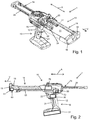
- FIG 1 and 2 A preferred embodiment of an extrusion system 1 according to the invention is shown in FIG 1 and 2 shown, wherein in Fig. 1 a pressing device 10 of the pressing system 1 and in Fig. 2 a cartridge device 40 of the extrusion system 1 is shown.
- the squeezing device 10 can in principle be designed to squeeze one-component and in the present case in particular multi-component masses, the masses being able to be provided, for example, for filling, gluing or sealing or similar applications in the construction sector. Such and other masses are arranged in one or more cartridges of a cartridge device.
- the squeezing device 10 is for interaction with an in Fig. 3 shown cartridge device 40, which has two containers designed as cartridges 41 and 42.
- the cartridge device 40 can be arranged in a receiving space 11 of a housing 12 of the extrusion device 10 and can contain, for example, a two-component mortar composition.
- a curable resin component can be arranged in a chamber or cartridge 41 of the cartridge device 40 and a hardener component can be arranged in the further chamber or cartridge 42 of the cartridge device 40, which is arranged separately from the latter to inhibit the reaction.
- the mass formed after mixing the hardenable resin component and the hardener component is used, for example, as injection mortar for the chemical anchoring of, for example, metal elements in mineral substrates, such as, in particular, structures made of brickwork, concrete or natural stone.
- injection mortar for the chemical anchoring of, for example, metal elements in mineral substrates, such as, in particular, structures made of brickwork, concrete or natural stone.
- the boreholes required for fastening the anchoring means are made in the mineral substrate, after which the hardenable resin component is mixed with the hardening component of the two-component mortar composition and introduced into the borehole, whereupon the anchoring agent to be fastened is inserted and adjusted and the mortar composition then hardens.
- the housing 12 of the pressing device 10 extends essentially along an axial direction A and has a functional section 14 and a handling section 16.
- the functional section 14 essentially has the receiving space 11 and a processing head 19 on a processing-side distal end 18 of the functional section 14, into which a squeeze opening of the cartridges 41, 42 extends. Masses dispensed from the cartridges 41, 42 are mixed in particular in a mixing area 49 of the cartridge device 40 and are dispensed at the processing-side distal end 18 of the functional section 14 to a location to be processed.
- the handling section 16 of the housing 12 has, in addition to a handle 21, an actuating switch 22 which is arranged in the region of the handle 21 and which can be embodied, for example, as a so-called MOSFET switch.
- a squeezing device 24 is provided, which in the present case is designed with two squeezing pistons 25, 26, which in the present case are firmly connected to one another via a push rod 29.
- Each ejection piston 25, 26 has a punch 27 or 28 at its end facing the respective cartridge 41 or 42.
- a drive device shown here only schematically, in particular in the form of an electric motor 30, is provided, by means of which the pressing-out pistons 25, 26 can be displaced in the axial direction A.
- the squeezing pistons 25, 26 can also be operated by means of compressed air or by means of a hydraulic drive.
- the squeeze pistons 25, 26 can be moved together in the direction of the distal end 18 via the push rod 29 which can be driven by the electric motor 30 in a feed direction V.
- the electric motor 30 is only one in Fig. 2 schematically shown and supplied as an accumulator 31 energy supply with energy.
- the squeezing device 10 can also be network-operated, it being possible to provide a plug which can be coupled to a power network.
- the squeezing device 10 also has a control device 33 which is designed to actuate the electric motor 30 according to a user request by means of the actuation switch 22.
- the electric motor 30 can be put into different operating modes by the control device 33, a first operating mode corresponding to a deactivation mode in which no current is fed from the accumulator 31 to the electric motor 30 and actuation of the actuation switch 22 does not lead to a displacement of the push rod 29 .
- a second operating mode corresponds to normal or regular operation of the electric motor 30, in which actuation of the actuation switch 22 by the user leads to a displacement of the squeeze-out pistons 25 and 26 in the feed direction V at a first speed.
- the electric motor 30 can, in particular, also be put into a third operating mode by the control device 33, in which actuation of the actuation switch 22 by the user leads to a displacement of the squeeze-out pistons 25 and 26 in the feed direction V at a second speed that is reduced compared to the first speed.
- the cartridges 41, 42 of the cartridge device 40 each have an essentially cylindrical base body 43 or 44 with a first end wall 45 or 46 and an opposite second end wall 47 or 48.
- a dispensing opening is provided on the first end wall 45 and 46, respectively, which are connected to one another via the mixing region 49.
- an output device in the form of a spout can be connected to the mixing area 49.
- the second end wall 47 or 48 is for cooperation with the plunger 27 or 28 of the respective ejection piston 25 or 26, with a displacement of the ejection piston 25 or 26 in the feed direction V in the direction of the first end wall 45 or 46, a volume of the base body 43 or 44 of the respective cartridge 41 or 42 is reduced, so that the respective mass in the cartridges 41 and 42 is carried out through the dispensing opening, mixed with one another in the mixing region 49 and pressed out via the dispensing device.
- the squeezing system 1 also has a transmission device 60 which has at least one sensor 61 arranged on the squeezing device 10 and a signal transmitter 62 arranged on the cartridge device 40.
- the transmission device 60 is designed wirelessly and can operate using a variety of transmission principles. In particular, it is an RFID transmission device, but it can alternatively also be, for example, a Bluetooth transmission device, an NFC transmission device, a WiFi transmission device, a QR transmission device, a DMC transmission device, a WLAN transmission device, a ZigBee transmission device, a Wibree transmission device, a WiMAX transmission device, an IrDA transmission device or a transmission device operating according to optical directional radio.
- the signal transmitter 62 is arranged on an end face 50 of the mixing region 49 of the cartridge device 40
- the sensor 61 is arranged on the housing 12 of the dispenser 10 in such a way that the signal transmitter 62 of the cartridge device 40 with the cartridge device 40 arranged in the receiving space 11 in a prescribed manner interacts with the sensor 61 and signals can be transmitted from the signal generator 62 to the sensor 61.
- the sensor 61 is arranged, for example, in the region of a wall of the housing 12 which delimits a distal end region of the receiving region 11.
- the sensor 61 is coupled to the control device 33 by means of a further transmission device 65, it being possible for the further transmission device 65 to be implemented wirelessly or by wire.
- the further transmission device 65 can be designed on the basis of the same transmission mechanisms as the transmission device 60.
- Fig. 4 An embodiment of a method according to the invention for operating the squeezing system 1 is shown, wherein the method can be used, for example, to determine whether a compatible system consisting of a squeezing device 10 and a cartridge device 40 is present. This can reliably prevent damage to both the dispenser 10 and the cartridge device 40. Furthermore, for example, the risk of damage as a result of incorrect operation can be reduced or prevented.
- step S1 the cartridge device 40 is inserted into the receiving space 11.
- step S2 the signal transmitter 62 sends the cartridge device 40 a first signal, which in particular identifies the cartridge device 40 with regard to type, size, shape and the like.
- the cartridge device 40 in the present case additionally sends out a third signal, which includes, for example, a date of expiration of the cartridge device 40, a permissible temperature range in the surrounding area for processing or the like.
- the signals emitted by the cartridge device 40 are received by the sensor 61 of the extrusion device 10 in step S3 with the cartridge device 40 arranged in the receiving space 11 in a prescribed manner.
- step S4 second signals corresponding to the first signal and the third signal or generated from the first signal and the third signal are sent from the sensor 61 to the control device 33.
- the second signal which correlates with the third signal, is compared, for example, with a current ambient temperature determined by a temperature sensor and, in the event that the currently existing ambient temperature is within a permissible temperature range for the cartridge device 40, continue with query step S6.
- it can be compared in query step S5 whether the current date lies before the permissible expiration date of the cartridge device 40. If the result is positive, continue with query step S6.
- the electric motor 30 is set by the control device 33 in step S7 into the first operating mode, i. that is, the electric motor 30 remains in the first operating mode if it was already there before, or the electric motor 30 is switched to the first operating mode if it was previously in another operating mode.
- actuation of the actuation switch 22 does not lead to a displacement of the push rod 29 and thus of the squeezing pistons 25 and 26.
- the second signal correlating with the first signal is compared with values stored in the control device 33, for example in the form of a look-up table, or verified by means of an algorithm stored in the control device 33. If the result of the comparison or the verification is positive, the electric motor 30 is transferred from the control device 33 to the second operating mode in step S8, whereas the electric motor 30 is transferred to the third operating mode in step S9 in the query step S6 in step S9. As an alternative to this, it can also be provided that the electric motor 30 is switched to the first operating mode in step S9. In the second operating mode of the electric motor 30, a user request results by actuating the actuation switch 22 for a displacement of the push rod 29 and thus for a displacement of the squeezing pistons 25, 26.
- step S10 a query is made as to whether relevant framework conditions to be defined have changed to a predetermined extent. If the result of the query is positive, the method continues at step S1. If the query result is negative, the method is ended in step E.
- the squeezing device 10 has, in particular, an output device 70, which is designed, for example, to output a warning signal in an optical, acoustic and / or haptic manner when the electric motor 30 is set in the first operating mode by the control device 33 in step S7 and / or in step S9 is transferred to the third operating mode.
- the control device 33 can also have a memory device 72, which is designed for at least temporarily storing the first signal, the second signal and / or the third signal, and which can be read out via an output device. In this way, usage information of the pressing system 1 can be evaluated in a simple manner.
Landscapes
- Engineering & Computer Science (AREA)
- Mechanical Engineering (AREA)
- Coating Apparatus (AREA)
- Application Of Or Painting With Fluid Materials (AREA)
- Containers And Packaging Bodies Having A Special Means To Remove Contents (AREA)
- Devices For Dispensing Beverages (AREA)
- Feeding, Discharge, Calcimining, Fusing, And Gas-Generation Devices (AREA)
Priority Applications (9)
| Application Number | Priority Date | Filing Date | Title |
|---|---|---|---|
| EP18212571.6A EP3666400A1 (de) | 2018-12-14 | 2018-12-14 | Verfahren zum betreiben eines auspresssystems und auspresssystem |
| CA3118180A CA3118180A1 (en) | 2018-12-14 | 2019-11-25 | Method for operating a dispensing system and dispensing system |
| EP19806250.7A EP3894096B1 (de) | 2018-12-14 | 2019-11-25 | Verfahren zum betreiben eines auspresssystems und auspresssystem |
| US17/298,722 US11673160B2 (en) | 2018-12-14 | 2019-11-25 | Method for operating a dispensing system and dispensing system |
| PL19806250.7T PL3894096T3 (pl) | 2018-12-14 | 2019-11-25 | Sposób obsługi układu wyciskającego i układ wyciskający |
| PCT/EP2019/082355 WO2020120112A1 (de) | 2018-12-14 | 2019-11-25 | Verfahren zum betreiben eines auspresssystems und auspresssystem |
| AU2019396381A AU2019396381B2 (en) | 2018-12-14 | 2019-11-25 | Method for operating a dispensing system and dispensing system |
| JP2021530051A JP7429495B2 (ja) | 2018-12-14 | 2019-11-25 | 吐出システムを動作させるための方法および吐出システム |
| ES19806250T ES2992831T3 (en) | 2018-12-14 | 2019-11-25 | Pressing system and method for operating a pressing system |
Applications Claiming Priority (1)
| Application Number | Priority Date | Filing Date | Title |
|---|---|---|---|
| EP18212571.6A EP3666400A1 (de) | 2018-12-14 | 2018-12-14 | Verfahren zum betreiben eines auspresssystems und auspresssystem |
Publications (1)
| Publication Number | Publication Date |
|---|---|
| EP3666400A1 true EP3666400A1 (de) | 2020-06-17 |
Family
ID=64665554
Family Applications (2)
| Application Number | Title | Priority Date | Filing Date |
|---|---|---|---|
| EP18212571.6A Withdrawn EP3666400A1 (de) | 2018-12-14 | 2018-12-14 | Verfahren zum betreiben eines auspresssystems und auspresssystem |
| EP19806250.7A Active EP3894096B1 (de) | 2018-12-14 | 2019-11-25 | Verfahren zum betreiben eines auspresssystems und auspresssystem |
Family Applications After (1)
| Application Number | Title | Priority Date | Filing Date |
|---|---|---|---|
| EP19806250.7A Active EP3894096B1 (de) | 2018-12-14 | 2019-11-25 | Verfahren zum betreiben eines auspresssystems und auspresssystem |
Country Status (8)
| Country | Link |
|---|---|
| US (1) | US11673160B2 (pl) |
| EP (2) | EP3666400A1 (pl) |
| JP (1) | JP7429495B2 (pl) |
| AU (1) | AU2019396381B2 (pl) |
| CA (1) | CA3118180A1 (pl) |
| ES (1) | ES2992831T3 (pl) |
| PL (1) | PL3894096T3 (pl) |
| WO (1) | WO2020120112A1 (pl) |
Families Citing this family (4)
| Publication number | Priority date | Publication date | Assignee | Title |
|---|---|---|---|---|
| EP3666401A1 (de) * | 2018-12-14 | 2020-06-17 | Hilti Aktiengesellschaft | Verfahren zum betreiben eines auspresssystems und auspresssystem |
| CA3127778A1 (en) * | 2019-01-28 | 2020-08-06 | Bayer Cropscience Lp | Applicator for pesticides |
| EP4011507A1 (en) | 2020-12-10 | 2022-06-15 | Hilti Aktiengesellschaft | A dispenser and a control method of the dispenser |
| EP4011505A1 (en) | 2020-12-10 | 2022-06-15 | Hilti Aktiengesellschaft | A dispenser and a control method of the dispenser |
Citations (5)
| Publication number | Priority date | Publication date | Assignee | Title |
|---|---|---|---|---|
| DE102011075873A1 (de) * | 2011-05-16 | 2012-11-22 | Hilti Aktiengesellschaft | Auspressgerät und Gebinde für ein Auspressgerät |
| US20130075427A1 (en) * | 2011-09-28 | 2013-03-28 | Ksaria Corporation | Epoxy dispensing system and dispensing tip used therewith |
| US20140209630A1 (en) * | 2013-01-31 | 2014-07-31 | Owens Corning Intellectual Capital, Llc | Method and apparatus for mixing and applying material |
| DE102016213882A1 (de) * | 2016-07-28 | 2018-02-01 | Robert Bosch Gmbh | Mobile Dosiervorrichtung |
| US20180185117A1 (en) * | 2015-07-02 | 2018-07-05 | Ivoclar Vivadent Ag | Injection Device |
Family Cites Families (12)
| Publication number | Priority date | Publication date | Assignee | Title |
|---|---|---|---|---|
| US5556009A (en) * | 1994-07-18 | 1996-09-17 | Wagner Spray Tech Corporation | Adjustable constant pressure caulk gun |
| EP2382941A1 (en) * | 2010-04-29 | 2011-11-02 | 3M Innovative Properties Company | A system comprising a mixing and dispensing device and a material container |
| US8573450B2 (en) * | 2011-08-15 | 2013-11-05 | Techway Industrial Co., Ltd. | Electrical caulking gun |
| AU2012365673B2 (en) * | 2012-01-12 | 2016-11-17 | Sulzer Mixpac Ag | A motorized viscous material dispenser |
| JP6141875B2 (ja) * | 2012-01-12 | 2017-06-07 | スルザー ミックスパック デンマーク アクティーゼルスカブ | 電動粘性材料分配器及び分配器を動作させる方法 |
| US8957608B2 (en) * | 2013-01-15 | 2015-02-17 | Techway Industrial Co., Ltd. | Motor-driving device of an electric caulking gun |
| EP2923774B1 (en) * | 2014-03-24 | 2019-02-13 | Sulzer Mixpac AG | Dispenser |
| US9862001B2 (en) * | 2015-12-31 | 2018-01-09 | Sulzer Mixpac Ag | Dispensing device |
| CA3010608C (en) * | 2016-01-05 | 2024-09-17 | Gojo Industries, Inc. | SYSTEMS AND METHODS FOR MONITORING AND REGULATING DISPENSER FLUID REFILL |
| US10334837B1 (en) * | 2018-02-14 | 2019-07-02 | Bayer Cropscience Lp | Applicator for pesticides with trigger and cartridge |
| US10894272B2 (en) * | 2018-06-29 | 2021-01-19 | Sulzer Mixpac Ag | Dispensing control system |
| BR112020025252A8 (pt) * | 2018-06-29 | 2023-03-21 | Sulzer Mixpac Ag | Sistema de controle de dispensação, método de controle de um dispositivo de dispensação e programa de computador |
-
2018
- 2018-12-14 EP EP18212571.6A patent/EP3666400A1/de not_active Withdrawn
-
2019
- 2019-11-25 PL PL19806250.7T patent/PL3894096T3/pl unknown
- 2019-11-25 US US17/298,722 patent/US11673160B2/en active Active
- 2019-11-25 WO PCT/EP2019/082355 patent/WO2020120112A1/de not_active Ceased
- 2019-11-25 CA CA3118180A patent/CA3118180A1/en active Pending
- 2019-11-25 ES ES19806250T patent/ES2992831T3/es active Active
- 2019-11-25 AU AU2019396381A patent/AU2019396381B2/en active Active
- 2019-11-25 EP EP19806250.7A patent/EP3894096B1/de active Active
- 2019-11-25 JP JP2021530051A patent/JP7429495B2/ja active Active
Patent Citations (5)
| Publication number | Priority date | Publication date | Assignee | Title |
|---|---|---|---|---|
| DE102011075873A1 (de) * | 2011-05-16 | 2012-11-22 | Hilti Aktiengesellschaft | Auspressgerät und Gebinde für ein Auspressgerät |
| US20130075427A1 (en) * | 2011-09-28 | 2013-03-28 | Ksaria Corporation | Epoxy dispensing system and dispensing tip used therewith |
| US20140209630A1 (en) * | 2013-01-31 | 2014-07-31 | Owens Corning Intellectual Capital, Llc | Method and apparatus for mixing and applying material |
| US20180185117A1 (en) * | 2015-07-02 | 2018-07-05 | Ivoclar Vivadent Ag | Injection Device |
| DE102016213882A1 (de) * | 2016-07-28 | 2018-02-01 | Robert Bosch Gmbh | Mobile Dosiervorrichtung |
Also Published As
| Publication number | Publication date |
|---|---|
| US20220048064A1 (en) | 2022-02-17 |
| EP3894096B1 (de) | 2024-08-28 |
| JP7429495B2 (ja) | 2024-02-08 |
| ES2992831T3 (en) | 2024-12-18 |
| JP2022510192A (ja) | 2022-01-26 |
| WO2020120112A1 (de) | 2020-06-18 |
| EP3894096A1 (de) | 2021-10-20 |
| AU2019396381A1 (en) | 2021-05-27 |
| AU2019396381B2 (en) | 2025-01-16 |
| PL3894096T3 (pl) | 2025-02-24 |
| CA3118180A1 (en) | 2020-06-18 |
| US11673160B2 (en) | 2023-06-13 |
Similar Documents
| Publication | Publication Date | Title |
|---|---|---|
| EP3894096B1 (de) | Verfahren zum betreiben eines auspresssystems und auspresssystem | |
| EP2809956B1 (de) | Ankersystem, insbesondere hinterschnittankersystem | |
| EP3666401A1 (de) | Verfahren zum betreiben eines auspresssystems und auspresssystem | |
| EP3632567A1 (de) | Pipettiervorrichtung zur pipettierung kleiner flüssigkeitsvolumina | |
| DE2245413B2 (de) | Pipette | |
| DE102009045891A1 (de) | Auspressvorrichtung | |
| DE102015218508A1 (de) | Messwertübertragungssystem für handgeführte Metrologieinstrumente | |
| EP4058249A1 (de) | Verfahren zum steuern und regeln einer werkzeugmaschine | |
| DE102020115024A1 (de) | Handgerät mit Sensoreinrichtung zum Charakterisieren eines bearbeiteten Untergrunds | |
| EP3820614A1 (de) | Pipettiervorrichtung zur impulsartigen pipettierung mit einer basierend auf einer erfassung der kolbenposition geregelten pipettierkolbenbewegung | |
| EP3237151B1 (de) | Handwerkzeug sowie vorrichtung umfassend das handwerkzeug | |
| DE102015210716B4 (de) | Positionssensor sowie Verfahren zum Betreiben eines Positionssensors | |
| EP4316737A1 (de) | Fernsteuerbare werkzeugmaschine zur nutzung durch einen bauroboter und system | |
| DE102019125562A1 (de) | Stanznietvorrichtung und verfahren zum betreiben einer stanznietvorrichtung, um eine inkorrekte matrizenverwendung zu verhindern | |
| DE102011003127A1 (de) | Befestigungsset und Verfahren zur Befestigung eines Bauteils an einem Untergrund | |
| EP3663061A1 (de) | Verfahren zum betreiben eines systems und system | |
| EP4484020A1 (de) | Verfahren zum betreiben eines auspressgeräts und auspressgerät | |
| DE102018131088A1 (de) | Flüssigkeitsdosiervorrichtung zur ballistischen Abgabe von Dosiermengen im Nanoliterbereich, Flüssigkeitsdosierverfahren und Pipettierspitze hierfür | |
| WO2015124667A1 (de) | Vorrichtung zum einbringen einer dübelmasse in eine öffnung | |
| EP3891963B1 (de) | Verfahren zum betreiben eines systems und korrespondierendes system | |
| EP3891567B1 (de) | Verfahren zum betreiben eines systems und system | |
| EP2452742A1 (de) | Kontrolleinrichtung für eine Mischvorrichtung | |
| EP3664059A1 (de) | Verfahren zum betreiben eines systems und system | |
| EP1287966B1 (de) | Positionierung einer Verriegelungskassette | |
| EP2338589A1 (de) | Verfahren und Vorrichtung zum Zubereiten von Massen aus mindestens zwei Komponenten |
Legal Events
| Date | Code | Title | Description |
|---|---|---|---|
| PUAI | Public reference made under article 153(3) epc to a published international application that has entered the european phase |
Free format text: ORIGINAL CODE: 0009012 |
|
| STAA | Information on the status of an ep patent application or granted ep patent |
Free format text: STATUS: THE APPLICATION HAS BEEN PUBLISHED |
|
| AK | Designated contracting states |
Kind code of ref document: A1 Designated state(s): AL AT BE BG CH CY CZ DE DK EE ES FI FR GB GR HR HU IE IS IT LI LT LU LV MC MK MT NL NO PL PT RO RS SE SI SK SM TR |
|
| AX | Request for extension of the european patent |
Extension state: BA ME |
|
| STAA | Information on the status of an ep patent application or granted ep patent |
Free format text: STATUS: THE APPLICATION IS DEEMED TO BE WITHDRAWN |
|
| 18D | Application deemed to be withdrawn |
Effective date: 20201218 |