EP3666380A1 - Vorrichtung zum dosieren von chemikalien - Google Patents
Vorrichtung zum dosieren von chemikalien Download PDFInfo
- Publication number
- EP3666380A1 EP3666380A1 EP19214466.5A EP19214466A EP3666380A1 EP 3666380 A1 EP3666380 A1 EP 3666380A1 EP 19214466 A EP19214466 A EP 19214466A EP 3666380 A1 EP3666380 A1 EP 3666380A1
- Authority
- EP
- European Patent Office
- Prior art keywords
- syringe
- glass tube
- covering
- plunger
- screw threads
- Prior art date
- Legal status (The legal status is an assumption and is not a legal conclusion. Google has not performed a legal analysis and makes no representation as to the accuracy of the status listed.)
- Granted
Links
Images

Classifications
-
- B—PERFORMING OPERATIONS; TRANSPORTING
- B01—PHYSICAL OR CHEMICAL PROCESSES OR APPARATUS IN GENERAL
- B01L—CHEMICAL OR PHYSICAL LABORATORY APPARATUS FOR GENERAL USE
- B01L3/00—Containers or dishes for laboratory use, e.g. laboratory glassware; Droppers
- B01L3/02—Burettes; Pipettes
- B01L3/021—Pipettes, i.e. with only one conduit for withdrawing and redistributing liquids
- B01L3/0217—Pipettes, i.e. with only one conduit for withdrawing and redistributing liquids of the plunger pump type
-
- A—HUMAN NECESSITIES
- A61—MEDICAL OR VETERINARY SCIENCE; HYGIENE
- A61M—DEVICES FOR INTRODUCING MEDIA INTO, OR ONTO, THE BODY; DEVICES FOR TRANSDUCING BODY MEDIA OR FOR TAKING MEDIA FROM THE BODY; DEVICES FOR PRODUCING OR ENDING SLEEP OR STUPOR
- A61M5/00—Devices for bringing media into the body in a subcutaneous, intra-vascular or intramuscular way; Accessories therefor, e.g. filling or cleaning devices, arm-rests
- A61M5/178—Syringes
- A61M5/31—Details
- A61M5/3129—Syringe barrels
-
- A—HUMAN NECESSITIES
- A61—MEDICAL OR VETERINARY SCIENCE; HYGIENE
- A61M—DEVICES FOR INTRODUCING MEDIA INTO, OR ONTO, THE BODY; DEVICES FOR TRANSDUCING BODY MEDIA OR FOR TAKING MEDIA FROM THE BODY; DEVICES FOR PRODUCING OR ENDING SLEEP OR STUPOR
- A61M5/00—Devices for bringing media into the body in a subcutaneous, intra-vascular or intramuscular way; Accessories therefor, e.g. filling or cleaning devices, arm-rests
- A61M5/178—Syringes
- A61M5/31—Details
- A61M5/3129—Syringe barrels
- A61M2005/3142—Modular constructions, e.g. supplied in separate pieces to be assembled by end-user
-
- B—PERFORMING OPERATIONS; TRANSPORTING
- B01—PHYSICAL OR CHEMICAL PROCESSES OR APPARATUS IN GENERAL
- B01L—CHEMICAL OR PHYSICAL LABORATORY APPARATUS FOR GENERAL USE
- B01L2200/00—Solutions for specific problems relating to chemical or physical laboratory apparatus
- B01L2200/02—Adapting objects or devices to another
- B01L2200/025—Align devices or objects to ensure defined positions relative to each other
-
- B—PERFORMING OPERATIONS; TRANSPORTING
- B01—PHYSICAL OR CHEMICAL PROCESSES OR APPARATUS IN GENERAL
- B01L—CHEMICAL OR PHYSICAL LABORATORY APPARATUS FOR GENERAL USE
- B01L2200/00—Solutions for specific problems relating to chemical or physical laboratory apparatus
- B01L2200/06—Fluid handling related problems
- B01L2200/0689—Sealing
-
- B—PERFORMING OPERATIONS; TRANSPORTING
- B01—PHYSICAL OR CHEMICAL PROCESSES OR APPARATUS IN GENERAL
- B01L—CHEMICAL OR PHYSICAL LABORATORY APPARATUS FOR GENERAL USE
- B01L2300/00—Additional constructional details
- B01L2300/12—Specific details about materials
-
- B—PERFORMING OPERATIONS; TRANSPORTING
- B01—PHYSICAL OR CHEMICAL PROCESSES OR APPARATUS IN GENERAL
- B01L—CHEMICAL OR PHYSICAL LABORATORY APPARATUS FOR GENERAL USE
- B01L2400/00—Moving or stopping fluids
- B01L2400/04—Moving fluids with specific forces or mechanical means
- B01L2400/0475—Moving fluids with specific forces or mechanical means specific mechanical means and fluid pressure
- B01L2400/0478—Moving fluids with specific forces or mechanical means specific mechanical means and fluid pressure pistons
Definitions
- the present invention relates to a device for metering liquids and chemicals by means of a syringe meter.
- glass borosilicate glass
- fluoroplastics such as polytetrafluoroethylene (PTFE) or thermoplastics (e.g. PEEK) are preferably used as media-carrying parts. When it comes into contact with media, there is a high level of compatibility for these connections.
- PTFE polytetrafluoroethylene
- PEEK thermoplastics
- the plastic is used as a seal.
- adhesive connections are used for the connection between glass and plastic. However, these are not resistant to all chemicals. I.e. There may be signs of detachment due to the use of chemicals or pressure, so that the dosing syringe leaks.
- connection of the components themselves should be resistant to aggressive chemicals and also be able to withstand high pressures and high temperatures without a solution to the connection mechanism.
- the present invention therefore relates in particular to a device for metering fluids by means of a metering syringe, comprising a syringe plunger guided through a glass tube, a syringe head which is non-positively and adhesive-free by means of a press connection on the glass tube, in which the syringe plunger is provided with a covering, and lids are arranged at the ends of the wrapping.
- This device has screw threads which are compatible with one another on the lids and the ends of the casing.
- the present disclosure also provides a device for metering liquids and chemicals by means of a metering syringe, comprising a syringe plunger which is guided through a glass tube and has a syringe head which is arranged on the glass tube in a force-locking and adhesive-free manner by means of a press connection.
- the glass tube is encased in a covering.
- a covering can be made of any materials, preferably made of metal, or contain metal.
- metal for example, stainless steel, aluminum or aluminum alloys come into consideration as metals for the covering.
- Plastics are also suitable for the wrapping.
- the plastic is used for the casing selected from the group consisting of polycarbonate, polypropylene, cycloolefin copolymers, polystyrene, polyaryl ether ketones and mixtures and compounds thereof.
- polyether ether ketones PEEK
- the covering can consist of PEEK.
- a casing is made of metal, which has a recess along its length, into which plastic is then inserted; this corresponds to a design with a side window.
- a sheath made of plastic and metal only incorporated into the sheath for reinforcement or applied externally, for example in the form of metal rings.
- Polyether ether ketones which can be used in the context of the present invention are high-temperature-resistant thermoplastics which belong to the group of polyaryl ether ketones. In some cases, their melting temperature or melting range is around 335 ° C.
- the wrapper can be transparent, but is preferably not transparent. In this case it is therefore preferred to arrange windows on the sides in order to read values, e.g. an arranged scale.
- Lids are arranged at the ends of the casing. These have screw threads that are compatible with the ends of the casing, so that screwing is possible.
- the covers are preferably designed such that they are arranged non-destructively and can be detached again.
- the device has a syringe plunger cap which is screwed to the casing. It also has a syringe cover, which is also screwed to the casing. The syringe head is guided from the inside through the syringe cover to the outside.
- a glass tube inside the casing.
- the syringe plunger is guided through the glass tube in accordance with the prior art.
- a plastic disc can be placed between the piston cover and the glass tube.
- a syringe seal can also be inserted into the glass tube.
- the seal can consist of materials known to the person skilled in the art.
- Plastics are particularly suitable. These include elastomers, thermosets and thermoplastics. Soft materials are also considered, for example soft metals or metals which are designed to be elastic due to the geometry.
- Fluoropolymers can also be used. These include polytetrafluoroethylene (PTFE) or perfluoroalkoxy polymers (PFA). Fluorine compounds such as fluorine rubber or fluorine elastomers are also suitable. These include, for example, fluororubbers (FKM) or perfluororubbers (FFKM). Other plastics such as ultra-high molecular weight polyethylene (UHMWPE) can also be used.
- UHMWPE ultra-high molecular weight polyethylene
- Various metals, preferably gold or stainless steel, are also suitable. This list is not final. Any combinations of the materials in question can also be considered.
- the sealing surface of the syringe plunger with the syringe head provides a seal by pressing.
- the glass body is centered and this ensures that the opening of the syringe head lies exactly over the opening of the syringe seal.
- the pressing is achieved by a screw connection.
- all other pressing methods known to the person skilled in the art can also be used.
- the screw connection has the advantage, among other things, that the connection and the loosening can be accomplished very easily. Suitable mechanical methods can also be used to achieve a firm tightening without great effort. The mechanical strength of the syringe is greatly increased. This compensates for high forces which can arise from the compression of the fluid by the piston in the glass tube. With the screw connections according to the invention it is possible at any time to readjust or adjust the contact pressure.
- the screw connection enables the connection to be released easily, as a result of which maintenance of the device is simple and as a result of which the inner part of the device, that is to say essentially the glass tube, the syringe plunger or the casing, can also be replaced at any time.
- the configuration according to the invention makes it possible to provide a type of syringe kit in which different configurations are available for the various components of the device and the device is assembled accordingly if required.
- the system according to the invention thus does not have the disadvantages of the prior art.
- a further embodiment of the present invention is accordingly a syringe kit which contains at least one glass tube, at least one syringe plunger, at least one syringe head, at least one sheath with screw threads on both ends and at least two caps with screw threads which are compatible with the screw threads of the at least one sheath are included.
- the individual elements are coordinated with one another in terms of their dimensions and are each in different dimensions Refinements, in particular with regard to materials or material combinations. This provides a high degree of flexibility.
- This kit may also include needles for attachment to the syringe head.
- the device for dosing can be used in high pressure ranges (following information as absolute pressures).
- ranges from 0 - 300 bar, or from 100 to 200 bar can easily be named and implemented as areas of application.
- a pressure of up to 270 bar can preferably be readily used.
- the temperature ranges In preferred embodiments, the syringes can be used from -20 ° C to + 230 ° C.
- the devices according to the invention are suitable for liquids, emulsions, suspensions.
- the only limiting factor is that the glass and the plastics used are inert to the chemical compounds used.
- the device additionally includes a needle attached to the syringe head.
- a needle attached to the syringe head.
- This can preferably be a hollow needle, in particular as is known from the prior art. If necessary, the needle and the syringe head can have coordinated connecting elements.
- the injection plunger or syringe plunger extends only to the lower end of the glass plunger, but not into the syringe head. In further variants of the present invention, the injection plunger or syringe plunger extends only to the lower end of the syringe head, but not into an attached needle.
- the use of springs to generate clamping forces is completely dispensed with, i.e. the device does not include springs.
- the glass tube used is thick-walled.
- the modular structure of the system also makes it possible to replace the worn parts. Such an exchange is also possible if a change of material is necessary.
- the syringe head of a certain material can be exchanged for another with another material if this is necessary due to the change in the fluid to be metered.
- the modular construction also makes cleaning the components easier. Systems with different volumes can also be surrounded by one and the same covering, so that it is not necessary to use a separate covering for each syringe.
- the inner syringe seal 8 is at least partially inserted into the glass tube in advantageous configurations, whereby a particularly advantageous seal is achieved. This is achieved with high internal pressure a better seal than just placed seals, for example in the form of washers.
- the seal can be designed in the form of a hollow plug.
- the special advantages also include that a precaution against the glass body bursting or the connections between the glass body and metal is not necessary if the system threatens to burst at a high pressure, for example of 30 bar or more. This disadvantage occurs when gluing.
- Another advantage of the present invention is that the envelope surrounding the glass tube serves as a splinter protection in the event that the glass tube should break. This protection is further improved by the secure connection by means of the screwed lid in comparison to configurations without a lid or with "only" inserted lids.
- the present disclosure also relates to the following configuration: An apparatus for dosing fluids by means of a dosing syringe is disclosed.
- This device has a syringe plunger which is guided through a glass tube and has a syringe head. This can be non-positively and adhesive-free by means of a press connection on the glass tube.
- the syringe head can be released again without being destroyed.
- the syringe plunger can be provided with a covering.
- the casing that can be used in this context can be made of metal or contain metal, and in preferred variants it can consist of or can contain stainless steel, aluminum or aluminum alloys or plastics or any combination of these substances.
- the envelope so that it has at least one viewing window.
- lids on the ends of the casing, which can then have screw threads that are compatible with the ends of the casing.
- the seal can consist of plastics, preferably elastomers, thermosets, thermoplastics or soft metals or elastically designed metals, or contain these substances or a mixture of these substances. In this embodiment, it is preferred if the seal has fluoropolymers.
- the device according to this embodiment of the present disclosure can be used for metering fluids.
Landscapes
- Health & Medical Sciences (AREA)
- Clinical Laboratory Science (AREA)
- Chemical & Material Sciences (AREA)
- Chemical Kinetics & Catalysis (AREA)
- Vascular Medicine (AREA)
- Engineering & Computer Science (AREA)
- Anesthesiology (AREA)
- Biomedical Technology (AREA)
- Heart & Thoracic Surgery (AREA)
- Hematology (AREA)
- Life Sciences & Earth Sciences (AREA)
- Animal Behavior & Ethology (AREA)
- General Health & Medical Sciences (AREA)
- Public Health (AREA)
- Veterinary Medicine (AREA)
- Infusion, Injection, And Reservoir Apparatuses (AREA)
Abstract
Description
- Die vorliegende Erfindung betrifft eine Vorrichtung zur Dosierung von Flüssigkeiten und Chemikalien mittels eines Spritzendosierers.
- In der Biologie und Chemie werden vorzugsweise Glas (Borosilikatglas) und Fluor-Kunststoffe wie Polytetrafluorethylen (PTFE) oder auch Thermoplasten (z.B. PEEK) als medienführende Teile verwendet. Bei der Berührung mit Medien ist für diese Verbindungen eine hohe Verträglichkeit zu verzeichnen.
- Bei dieser Vorrichtung wird der Kunststoff als Dichtung verwendet. Für die Verbindung zwischen Glas und Kunststoff werden in der Praxis Klebverbindungen eingesetzt. Diese sind aber nicht gegen alle Chemikalien beständig. D.h. es kann zu Ablösungserscheinungen infolge des Einsatzes von Chemikalien oder auch von Druck kommen, so dass die Dosierspritze undicht wird.
- Die Verbindung von Glas und Metall ist dem Fachmann bekannt. So werden beispielsweise in der
DE 10 2008 042 80 A1 entsprechendEP 2 165 986 B1 spezielle Glaszusammensetzungen vorgestellt, die für solche Verbindungen geeignet sind.
Als weiterer Stand der Technik könnten beispielsweiseDE 10 2013 210 998 A1 ,DE 23 47 500 A ,DE 20 2007 013 096 U1 oder auchDE 1 129 717 A genannt werden. - Problematisch nach dem Stand der Technik ist es, dass Klebverbindungen sich lösen. Dies gilt insbesondere in dem Fall, dass eine Dosierung unter hohem Druck durchgeführt werden soll. Abgesehen davon können Unregelmäßigkeiten, nicht genaues Aufsetzen usw., zu einer verringerten Belastbarkeit führen.
- Aufgabe der vorliegenden Erfindung ist es nunmehr, diese Nachteile zu vermeiden. Insbesondere soll die Verbindung der Bauteile selbst gegen aggressive Chemikalien beständig sein und auch hohe Drucke und hohe Temperaturen ohne eine Lösung des Verbindungsmechanismus Bestand haben.
- Diese und weitere Aufgaben, die sich dem Fachmann bei Betrachtung der folgenden Beschreibung erschließen, werden durch die Gegenstände der unabhängigen Ansprüche gelöst. Vorteilhafte Weiterbildungen ergeben sich aus den Unteransprüchen und der folgenden Beschreibung.
- Gegenstand der vorliegenden Erfindung ist mithin insbesondere eine Vorrichtung zur Dosierung von Fluiden mittels einer Dosierspritze, aufweisend einen durch ein Glasrohr geführten Spritzenkolben, einen Spritzenkopf der kraftschlüssig und klebstofffrei mittels einer Pressverbindung am Glasrohr angeordnet ist, bei welcher der Spritzenkolben mit einer Umhüllung versehen ist, und an den Enden der Umhüllung Deckel angeordnet sind. Diese Vorrichtung weist an den Deckeln und den Enden der Umhüllung miteinander kompatible Schraubgewinde auf.
- Gegenstand der vorliegenden Offenbarung ist auch eine Vorrichtung zur Dosierung von Flüssigkeiten und Chemikalien mittels einer Dosierspritze gelöst, aufweisend einen durch ein Glasrohr geführten Spritzenkolben mit einem Spritzenkopf, der kraftschlüssig und klebstofffrei mittels einer Pressverbindung am Glasrohr angeordnet ist.
- Das Glasrohr wird erfindungsgemäß von einer Umhüllung ummantelt. Diese kann aus beliebigen Materialien, vorzugsweise aus Metall gefertigt sein, oder Metall enthalten. Als Metalle für die Umhüllung kommen beispielsweise Edelstahl, Aluminium oder Aluminiumlegierungen in Betracht. Ebenso kommen Kunststoffe für die Umhüllung in Betracht.
In einigen Ausgestaltungen der vorliegenden Erfindung wird der Kunststoff für die Umhüllung ausgewählt aus der Gruppe bestehend aus Polycarbonat, Polypropylen, Cycloolefin-Copolymeren, Polystyrol, Polyaryletherketonen und Gemischen sowie Verbunden davon eingesetzt.
In einer Ausgestaltung der vorliegenden Erfindung werden Polyetheretherketone (PEEK) zur Herstellung der Umhüllung eingesetzt. Die Umhüllung kann in einigen Ausgestaltungen aus PEEK bestehen.
Gleichsam ist es möglich, dass die Umhüllung aus Kombinationen dieser Stoffe besteht oder diese enthält. In einer Ausgestaltung der vorliegenden Erfindung wird eine Umhüllung aus Metall gefertigt, die über Ihre Länge hinweg eine Aussparung aufweist, in welche dann Kunststoff eingefügt ist; dies entspricht einer Ausgestaltung mit seitlichem Fenster. In einer weiteren Ausgestaltung der vorliegenden Erfindung wird eine Umhüllung aus Kunststoff gefertigt und Metall lediglich zur Verstärkung in die Umhüllung eingearbeitet bzw. außen aufgebracht, z.B. in Form von Metallringen. Im Rahmen der vorliegenden Erfindung einsetzbare Polyetheretherketone sind hochtemperaturbeständige thermoplastische Kunststoffe, welche zur Stoffgruppe der Polyaryletherketone gehören. Deren Schmelztemperatur bzw. Schmelzbereich liegt in einigen Fällen bei etwa 335°C. - Die Umhüllung kann durchsichtig sein, ist aber vorzugsweise nicht durchsichtig. In diesem Falle ist es daher bevorzugt, an den Seiten Fenster anzuordnen, um das Ablesen von Werten, z.B. einer angeordneten Skala, zu ermöglichen.
- An den Enden der Umhüllung sind Deckel angeordnet. Diese weisen mit den Enden der Umhüllung kompatible Schraubgewinde auf, so dass eine Verschraubung ermöglicht wird. Vorzugsweise sind die Deckel so beschaffen, dass sie zerstörungsfrei und wieder lösbar angeordnet sind. Im Ergebnis weist die Vorrichtung einen Spritzenkolbendeckel auf, welcher mit der Umhüllung verschraubt ist. Ferner weist sie einen Spritzendeckel auf, welcher ebenfalls mit der Umhüllung verschraubt wird. Hierbei wird der Spritzenkopf von innen durch den Spritzendeckel nach außen geführt.
- Im Inneren der Umhüllung befindet sich ein Glasrohr. Der Spritzenkolben wird entsprechend dem bisherigen Stand der Technik durch das Glasrohr geführt. Zur Vermeidung von direkten Kontaktflächen von Metall auf Glas kann eine Kunststoffscheibe zwischen dem Kolbendeckel und dem Glasrohr platziert werden.
- Im Weiteren kann eine Spritzendichtung in das Glasrohr eingeführt werden. Die Dichtung kann aus dem Fachmann bekannten Materialien bestehen. Insbesondere kommen Kunststoffe in Betracht. Hierzu zählen Elastomere, Duroplaste und Thermoplaste. In Betracht kommen auch weiche Materialien, z.B. weiche Metalle oder durch die Geometrie elastisch gestaltete Metalle. Ebenso können auch Fluorpolymere verwendet werden. Hierzu zählen Polytetrafluorethylen (PTFE)oder Perfluoralkoxy-Polymere (PFA). In Betracht kommen auch Fluor-Verbindungen wie Fluor-Kautschuk oder Fluor-Elastomere. Hierzu zählen z.B. Fluor-Kautschuke (FKM) oder Perfluorkautschuk (FFKM). Weiterhin kommen andere Kunststoffe wie Ultrahochmolekulares Polyethylen (UHMWPE) in Betracht. Weiterhin kommen auch verschiedene Metalle, vorzugsweise Gold oder Edelstahl in Betracht. Diese Aufzählung ist nicht abschließend. Auch kommen beliebige Kombinationen der betreffenden Materialien in Betracht.
- Die Dichtfläche des Spritzenkolbens mit dem Spritzenkopf sorgt durch das Anpressen für eine Dichtung. Der Glaskörper wird zentriert und es ist somit gewährleistet, dass die Öffnung des Spritzenkopfes genau über die Öffnung der Spritzendichtung liegt.
- Erfindungsgemäß wird das Anpressen durch eine Verschraubung erreicht.
In Varianten der vorliegenden Offenbarung sind auch alle anderen dem Fachmann bekannten Pressverfahren anwendbar.
Die Verschraubung bietet unter anderem den Vorteil, dass die Verbindung und auch das Lösen sehr leicht bewerkstelligt werden können. Durch geeignete mechanische Methoden kann ohne große Kraftanstrengung auch ein festes Anziehen erreicht werden. Die mechanische Belastbarkeit der Spritze wird stark erhöht. Hohe Kräfte, welche durch das Zusammenpressen des Fluids durch den Kolben in dem Glasrohr entstehen können, werden hiermit kompensiert. Bei den erfindungsgemäß Schraubverbindungen ist es jederzeit möglich, den Anpressdruck neu zu justieren oder nach zu justieren. Ebenso ermöglicht die Verschraubung ein einfaches Lösen der Verbindung, wodurch eine Wartung der Vorrichtung einfach ist und wodurch auch jederzeit der innere Teil der Vorrichtung, also im Wesentlichen das Glasrohr, der Spritzenkolben oder die Umhüllung getauscht werden können. Dies bedeutet eine sehr leichte und flexible Wartung; ebenso ist es durch die erfindungsgemäß Ausgestaltung möglich, eine Art Spritzenkit zur Verfügung zu stellen, bei dem für die verschiedenen Komponenten der Vorrichtung jeweils unterschiedliche Ausgestaltungen vorgehalten und bei Bedarf die Vorrichtung entsprechend zusammengesetzt wird.
Damit weist das erfindungsgemäße System nicht die Nachteile des Standes der Technik auf. - Eine weitere Ausgestaltung der vorliegenden Erfindung ist demgemäß ein Spritzenkit, welches als Bestandteile mindestens ein Glasrohr, mindestens einen Spritzenkolben, mindestens einen Spritzenkopf, mindestens eine Umhüllung mit Schraubgewinden an beiden Enden und mindestens zwei Deckel mit Schraubgewinden, die mit den Schraubgewinden der mindestens einen Umhüllung kompatibel sind, umfasst.
Bei diesem Kit sind die einzelnen Elemente einerseits in ihren Dimensionen aufeinander abgestimmt und liegen andererseits jeweils in verschiedenen Ausgestaltungen, insbesondere im Hinblick auf Materialien bzw. Materialkombinationen, vor. Dadurch wird eine hohe Flexibilität erreicht. Gegebenenfalls kann dieses Kit noch Nadeln zum Anbringen an dem Spritzenkopf umfassen. - Die Vorrichtung zur Dosierung kann in hohen Druckbereichen eingesetzt werden (nachfolgende Angaben als absolute Drucke). Hier lassen sich ohne Weiteres Bereiche von 0 - 300 bar, oder von 100 bis 200 bar als Einsatzgebiete nennen und realisieren. Erfindungsgemäß kann vorzugsweise mit einem Druck bis zu 270 bar ohne weiteres gearbeitet werden. Für die Temperaturbereiche gilt das Entsprechende. Die Spritzen können in bevorzugten Ausführungsformen von -20°C bis + 230°C zum Einsatz kommen.
- Die erfindungsgemäßen Vorrichtungen sind für Flüssigkeiten, Emulsionen, Suspensionen geeignet. Einziger begrenzender Faktor ist, dass das verwendete Glas und die verwendeten Kunststoffe inert gegen die eingesetzten chemischen Verbindungen sind.
- Erfindungswesentlich ist im Weiteren, dass kein Metall in Kontakt mit den chemischen Medien, welche mittels der erfindungsgemäßen Vorrichtung dosiert werden, in Berührung kommt. Weiterer Vorteil gegenüber dem Stand der Technik ist, dass auch flüssige organische Verbindungen mit der erfindungsgemäßen Vorrichtung dosiert werden können. Auch hier ist der erfindungsgemäße Vorteil darin zu sehen, dass das spezielle Dichtungssystem nicht angegriffen wird. Denn insbesondere waren Klebestoffverbindungen die Schwachstelle bei der Verwendung von aggressiven Fluiden.
- In manchen Varianten der vorliegenden Erfindung umfasst die Vorrichtung zusätzlich eine Nadel, die an dem Spritzenkopf angebracht ist. Dies kann bevorzugt eine Hohlnadel sein, insbesondere wie sie aus dem Stand der Technik bekannt sind. Gegebenenfalls können die Nadel und der Spritzenkopf aufeinander abgestimmte Verbindungselemente aufweisen.
- In Varianten der vorliegenden Erfindung erstreckt sich der Injektionskolben bzw. Spritzenkolben nur bis zum unteren Ende des Glaskolbens, aber nicht bis in den Spritzenkopf hinein.
In weiteren Varianten der vorliegenden Erfindung erstreckt sich der Injektionskolben bzw. Spritzenkolben nur bis zum unteren Ende des Spritzenkopfs, aber nicht bis in eine aufgesetzte Nadel hinein. - In bevorzugten Varianten der vorliegenden Erfindung wird gänzlich auf den Einsatz von Federn zur Erzeugung von Klemmkräften verzichtet, d.h. die Vorrichtung umfasst keine Federn.
- In bevorzugten Varianten der vorliegenden Erfindung ist das verwendete Glasrohr dickwandig. Dabei bedeutet "dickwandig" ein Verhältnis von Außendurchmesser zu Innendurchmesser von größer oder gleich 1,2 (D/d >=1,2). Dies ermöglicht, dass das Glasrohr höhere Kräfte aushält, ohne zu versagen. Dies ist vorteilhaft, weil dadurch in noch höherem Maße für das Abdichten bei höheren Betriebsdrucken erforderliche, hohe Kräfte auf den Glaszylinder aufgebracht werden können. In Kombination mit einer Umhüllung kann diese Druckwiderstandsfähigkeit nochmals gesteigert werden.
- Bei Einsatz einer Schraubverbindung ist von Vorteil, dass die Dichtung auch bei längerer Verwendung mit Hilfe des Spritzen- und Kolbendeckels einfach nachgezogen werden kann. Dies war bei Klebverbindungen nicht möglich. Durch den modularen Aufbau des Systems ist es auch möglich, die verschlissenen Teile wieder auszutauschen. Ebenso ist ein solcher Austausch möglich, wenn ein Materialwechsel vonnöten ist. So kann der Spritzenkopf eines bestimmten Materials gegen einen anderen mit einem anderen Material ausgetauscht werden, wenn dies aufgrund des Wechsels des zu dosierenden Fluids vonnöten ist. Ebenso wird das Reinigen der Bauteile durch den modularen Aufbau erleichtert. Auch können erfindungsgemäß Systeme mit unterschiedlichem Volumen von ein und derselben Umhüllung umgeben werden, so dass es nicht vonnöten ist, für jede Spritze eine separate Umhüllung zu verwenden.
- Bei der vorliegenden Erfindung ist die innere Spritzendichtung 8 in vorteilhaften Ausgestaltungen zumindest zum Teil in das Glasrohr eingeführt, wodurch eine besonders vorteilhafte Abdichtung erreicht wird. Bei hohem Innendruck erzielt dies eine bessere Abdichtung als nur aufgelegte Dichtungen z.B. in Form von Scheiben. Beispielsweise kann die Dichtung in Form eines Hohlstopfens ausgeführt sein.
- Zu den besonderen Vorteilen gehört auch, dass eine Vorkehrung gegen das Bersten des Glaskörpers oder der Verbindungen zwischen Glaskörper und Metall nicht erforderlich ist, falls das System bei einem hohen Druck, beispielsweise von 30 bar oder mehr zu platzen droht. Dieser Nachteil tritt nämlich bei Verklebungen auf. Weiterhin ist ein Vorteil der vorliegenden Erfindung, dass die das Glasrohr umgebende Hülle als Splitterschutz dient, für den Fall, dass das Glasrohr brechen sollte. Dieser Schutz wird durch die sichere Verbindung durch die geschraubten Deckel im Vergleich zu Ausgestaltungen ohne Deckel oder mit "nur" gesteckten Deckeln noch verbessert.
- Vorteilhaft bei der vorliegenden Erfindung gegenüber Vorrichtungen, bei denen z.B. die Deckel nur aufgeklemmt sind, ist, dass solche Klemmlösungen im Gegensatz zur vorliegenden Erfindung nicht kontrollier voneinander lösbar sind, d.h. sie sind oft so fest verbunden, dass sie nicht zerstörungsfrei lösbar sind oder aber sie sind zu leicht lösbar, können also keine Fixierung oder Sicherheit gewährleisten.
- Die vorliegende Offenbarung betrifft auch folgende Ausgestaltung:
Es wird eine Vorrichtung zur Dosierung von Fluiden mittels einer Dosierspritze offenbart. Dies Vorrichtung weist einen durch ein Glasrohr geführten Spritzenkolben mit einem Spritzenkopf auf. Dieser kann kraftschlüssig und klebstofffrei mittels einer Pressverbindung am Glasrohr angeordnet sein.
Gleichsam kann der Spritzenkopf in dieser Ausführungsform der vorliegenden Offenbarung zerstörungsfrei wieder lösbar sein. Zudem kann der Spritzenkolben mit einer Umhüllung versehen sein. - Die in diesem Zusammenhang einsetzbare Umhüllung kann aus Metall gefertigt sein oder Metall enthalten, wobei sie in bevorzugten Varianten aus Edelstahl, Aluminium oder Aluminium-Legierungen oder Kunststoffen oder beliebigen Kombinationen dieser Stoffe bestehen oder diese enthalten kann.
- Es ist dabei möglich, die Umhüllung so zu gestalten, dass sie mindestens ein Sichtfenster aufweist.
- Auch bei dieser Ausgestaltung der vorliegenden Offenbarung ist es möglich, an den Enden der Umhüllung Deckel anzuordnen, die dann mit den Enden der Umhüllung kompatible Schraubgewinde aufweisen können.
- Selbstverständlich ist es auch hier möglich zwischen dem Kolbendeckel und dem Ende des Glasrohrs des Spritzenkolbens eine Dichtungsscheibe anzuordnen.
- Weiterhin kann in dieser Ausgestaltung der vorliegenden Offenbarung die Dichtung aus Kunststoffen, vorzugsweise Elastomeren, Duroplasten, Thermoplasten oder weichen Metallen oder elastisch gestalteten Metallen bestehen, oder diese Stoffe oder ein Gemisch dieser Stoffe enthalten. Bevorzugt ist es in dieser Ausgestaltung, wenn die Dichtung Fluor-Polymere aufweist.
Die Vorrichtung gemäß dieser Ausgestaltung der vorliegenden Offenbarung kann zur Dosierung von Fluiden verwendet werden. - Im Folgenden wird die Erfindung anhand der Figuren näher beschrieben. Die Figuren sind dabei nicht maßstabsgetreu und nicht wesentliche Elemente werden nicht unbedingt dargestellt. Die Figuren sind darüber hinaus nur zur Illustration gedacht und schränken die vorliegende Erfindung nicht auf diese speziellen Ausführungsformen ein.
-
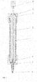
Figur 1 zeigt eine erfindungsgemäße Vorrichtung in Schnittdarstellung. Mit der Ziffer 1 ist eine Hülle bezeichnet, welche vorzugsweise aus Metall besteht oder dieses enthält. Nicht dargestellt sind die Fenster, welche beispielsweise dem Ablesen einer Scala dienen können, sofern die Umhüllung undurchsichtig ist. An die Umhüllung 1 wird der Spritzkolbendeckel 2 geschraubt. Mit der Umhüllung 1 wird im Weiteren der Spritzendeckel 3 verschraubt. Durch den Spritzendeckel 3 wird der Spritzenkopf 4 geführt. Im Inneren der Umhüllung 1 ist das Glasrohr 5 angeordnet. Der Spritzenkolben 6, der hier mit einem viereckigen Kopf dargestellt ist (dieser dient zur besseren Bedienbarkeit), wird durch das Glasrohr 5 geführt. Zwischen dem Spritzkolbendeckel 2 und dem Glasrohr 5 ist eine Kunststoffscheibe 7 angeordnet. Die Spritzendichtung 8 ist teilweise in das Innere des Glasrohrs 5 eingeführt. Mit Hilfe der durch die beiden Deckel 2 und 3 in Verbindung mit der Hülle 1 erzeugten Andruckkraft wird sie an die Dichtfläche des Spritzenkopfes 4 gepresst. -
Figur 2 ist eine schräge Draufsicht auf eine Vorrichtung gemäß vorliegender Erfindung. In dieser Illustration sind in der Umhüllung zwei längliche Vertiefungen dargestellt, die als (Sicht-)Fenster dienen können und wahlweise mit einem insbesondere durchsichtigen Material ausgefüllt sein können, was in dieser Figur nur angedeutet ist. -
- 1
- - Umhüllung
- 2
- - Kolbendeckel
- 3
- - Spritzendeckel
- 4
- - Spritzenkopf
- 5
- - Glasrohr
- 6
- - Spritzenkolben
- 7
- - Dichtscheibe
- 8
- - Spritzendichtung
Claims (10)
- Vorrichtung zur Dosierung von Fluiden mittels einer Dosierspritze, aufweisend einen durch ein Glasrohr (5) geführten Spritzenkolben (6), einen Spritzenkopf (4) der kraftschlüssig und klebstofffrei mittels einer Pressverbindung am Glasrohr (5) angeordnet ist,
wobei der Spritzenkolben (6) mit einer Umhüllung (1) versehen ist, und
wobei an den Enden der Umhüllung (1) Deckel (2,3) angeordnet sind, dadurch gekennzeichnet, dass die Deckel (2,3) und die Enden der Umhüllung (1,2) miteinander kompatible Schraubgewinde aufweisen. - Vorrichtung nach Anspruch 1, dadurch gekennzeichnet, dass die Umhüllung (1) aus Metall gefertigt ist oder Metall enthält.
- Vorrichtung nach Anspruch 2, dadurch gekennzeichnet, dass die Umhüllung aus Edelstahl, Aluminium oder Aluminium-Legierungen oder Kunststoffen oder beliebigen Kombinationen dieser Stoffe besteht oder diese enthält.
- Vorrichtung nach Anspruch 1 bis 3, dadurch gekennzeichnet, dass die Umhüllung (1) mindestens ein Sichtfenster aufweist.
- Vorrichtung nach einem der vorhergehenden Ansprüche, dadurch gekennzeichnet, dass zwischen dem Kolbendeckel (2) und dem Ende des Glasrohrs (5) des Spritzenkolbens (6) eine Dichtungsscheibe (7) angeordnet ist.
- Vorrichtung nach Anspruch 5, dadurch gekennzeichnet, dass die Dichtung (7) aus Kunststoffen, vorzugsweise Elastomeren, Duroplasten, Thermoplasten oder weichen Metallen oder elastisch gestalteten Metallen besteht, oder diese Stoffe oder ein Gemisch dieser Stoffe enthält.
- Vorrichtung nach Anspruch 6, dadurch gekennzeichnet, dass die Dichtung (7) Fluor-Polymere aufweist.
- Vorrichtung nach einem der vorhergehenden Ansprüche, dadurch gekennzeichnet, dass die Vorrichtung eine Nadel zur Anbringung an dem Spritzenkopf umfasst.
- Verwendung der Vorrichtungen nach einem der vorhergehenden Ansprüche zur Dosierung von Fluiden.
- Spritzenkit umfassend die folgenden Bestandteile,a) mindestens ein Glasrohr,b) mindestens einen Spritzenkolben,c) mindestens einen Spritzenkopf,d) mindestens eine Umhüllung mit Schraubgewinden an beiden Enden,e) mindestens zwei Deckel mit Schraubgewinden, die mit den Schraubgewinden der mindestens einen Umhüllung kompatibel sind,f) optional mindestens eine Nadel zur Anbringung an dem mindestens einen Spritzenkopf,
wobei die Elemente a) bis f) in ihren Dimensionen aufeinander abgestimmt sind und die Elemente a) bis f) jeweils in verschiedenen Ausgestaltungen, insbesondere im Hinblick auf Materialien bzw. Materialkombinationen, vorliegen,
insbesondere zur Herstellung von Vorrichtungen gemäß einem der Ansprüche 1 bis 8.
Applications Claiming Priority (1)
| Application Number | Priority Date | Filing Date | Title |
|---|---|---|---|
| DE102018131603.8A DE102018131603A1 (de) | 2018-12-10 | 2018-12-10 | Vorrichtung zum Dosieren von Chemikalien |
Publications (3)
| Publication Number | Publication Date |
|---|---|
| EP3666380A1 true EP3666380A1 (de) | 2020-06-17 |
| EP3666380C0 EP3666380C0 (de) | 2024-05-01 |
| EP3666380B1 EP3666380B1 (de) | 2024-05-01 |
Family
ID=68840925
Family Applications (1)
| Application Number | Title | Priority Date | Filing Date |
|---|---|---|---|
| EP19214466.5A Active EP3666380B1 (de) | 2018-12-10 | 2019-12-09 | Vorrichtung und verfahren zum dosieren von chemikalien |
Country Status (2)
| Country | Link |
|---|---|
| EP (1) | EP3666380B1 (de) |
| DE (1) | DE102018131603A1 (de) |
Citations (9)
| Publication number | Priority date | Publication date | Assignee | Title |
|---|---|---|---|---|
| US679198A (en) * | 1901-01-17 | 1901-07-23 | Charles Witkowski | Hypodermic syringe. |
| US2813528A (en) * | 1956-02-13 | 1957-11-19 | Omega Prec Medical Instr Co In | Hypodermic syringe |
| DE1129717B (de) | 1957-08-26 | 1962-05-17 | Beckman Instruments Inc | Spritze |
| DE2347500A1 (de) | 1972-09-22 | 1974-04-11 | Sge Res Pty Ltd | Injektionsspritze |
| WO1999021599A1 (en) * | 1997-10-24 | 1999-05-06 | Century Theodore J | Intrapulmonary aerosolizer |
| DE202007013096U1 (de) | 2007-09-19 | 2009-03-05 | Hamilton Bonaduz Ag | Spritze mit wechselbarer Nadel |
| US20140249410A1 (en) * | 2013-03-01 | 2014-09-04 | Medrad, Inc. | Information sensing syringe |
| DE102013210998A1 (de) | 2013-06-13 | 2014-12-18 | Hamilton Bonaduz Ag | Spritze mit mechanischem Kopplungsstück |
| EP2165986B1 (de) | 2008-09-16 | 2017-03-15 | Schott AG | Glas und Verwendung eines Glases für Glas-Metall-Verbindungen |
-
2018
- 2018-12-10 DE DE102018131603.8A patent/DE102018131603A1/de not_active Ceased
-
2019
- 2019-12-09 EP EP19214466.5A patent/EP3666380B1/de active Active
Patent Citations (9)
| Publication number | Priority date | Publication date | Assignee | Title |
|---|---|---|---|---|
| US679198A (en) * | 1901-01-17 | 1901-07-23 | Charles Witkowski | Hypodermic syringe. |
| US2813528A (en) * | 1956-02-13 | 1957-11-19 | Omega Prec Medical Instr Co In | Hypodermic syringe |
| DE1129717B (de) | 1957-08-26 | 1962-05-17 | Beckman Instruments Inc | Spritze |
| DE2347500A1 (de) | 1972-09-22 | 1974-04-11 | Sge Res Pty Ltd | Injektionsspritze |
| WO1999021599A1 (en) * | 1997-10-24 | 1999-05-06 | Century Theodore J | Intrapulmonary aerosolizer |
| DE202007013096U1 (de) | 2007-09-19 | 2009-03-05 | Hamilton Bonaduz Ag | Spritze mit wechselbarer Nadel |
| EP2165986B1 (de) | 2008-09-16 | 2017-03-15 | Schott AG | Glas und Verwendung eines Glases für Glas-Metall-Verbindungen |
| US20140249410A1 (en) * | 2013-03-01 | 2014-09-04 | Medrad, Inc. | Information sensing syringe |
| DE102013210998A1 (de) | 2013-06-13 | 2014-12-18 | Hamilton Bonaduz Ag | Spritze mit mechanischem Kopplungsstück |
Also Published As
| Publication number | Publication date |
|---|---|
| EP3666380C0 (de) | 2024-05-01 |
| DE102018131603A1 (de) | 2020-06-10 |
| EP3666380B1 (de) | 2024-05-01 |
Similar Documents
| Publication | Publication Date | Title |
|---|---|---|
| DE2930617C3 (de) | Schutzkappe für eine Probennadel | |
| EP2373550B1 (de) | Verschluss für einen behälter | |
| EP0226118B1 (de) | Behälter für aggressive Flüssigkeiten | |
| DE202015000520U1 (de) | Ventilblockanordnung für ein Flaschenaufsatzgerät | |
| EP3382239A1 (de) | Verschliessbare behälter-anordnung | |
| DE102010035887B4 (de) | Dosiergerät für Flüssigkeiten | |
| EP1281958B1 (de) | Vorrichtung zum Befestigen eines Sensors | |
| DE202005004079U1 (de) | Injektionsspritze für medizinische Zwecke | |
| DD244064A5 (de) | Isolierkanne mit abgedichtetem deckel | |
| EP3666380B1 (de) | Vorrichtung und verfahren zum dosieren von chemikalien | |
| DE102011112516B4 (de) | Gebinde mit einem Behälter zur Aufnahme einer Flüssigkeit und einer Flüssigkeitsentnahmeeinrichtung | |
| DE202012010883U1 (de) | Anschlussflansch zum Anschweißen an ein Anlagenbauteil | |
| DE19536258C5 (de) | Flaschendispenser | |
| DE2659627B2 (de) | Vorrichtung zur Trennung chemischer Substanzen unter Erzeugung von Sterillösungen | |
| EP2358606A1 (de) | Behältnis mit einem septumverschluss und verschlusskappe mit septumverschluss | |
| DE102023100940B4 (de) | Verschlussvorrichtung in Form einer Kappe zum fluiddichten Verschließen einer Düse und System mit einer Verschlussvorrichtung und einer Düse | |
| DE10227905B4 (de) | Anschlusselement | |
| WO1989001879A1 (fr) | Raccord a visser dans l'ouverture d'un recipient | |
| DE2145962A1 (de) | Injektionsspritze | |
| DE102015000902B4 (de) | Ausstoßleitungsanordnung für ein Flaschenaufsatzgerät | |
| DE102014003771B4 (de) | Wiederabdichtbare Ausgabeeinrichtung zur Ausgabe von Fluiden | |
| DE7019684U (de) | Mikrotrennsaeule fuer fluessigkeits-chromatographie. | |
| EP1340543A1 (de) | Mikrofluidsystem | |
| DE102015017471B3 (de) | Aussstoßleitungsanordnung für ein Flaschenaufsatzgerät | |
| DE29817009U1 (de) | Detektorzelle |
Legal Events
| Date | Code | Title | Description |
|---|---|---|---|
| PUAI | Public reference made under article 153(3) epc to a published international application that has entered the european phase |
Free format text: ORIGINAL CODE: 0009012 |
|
| STAA | Information on the status of an ep patent application or granted ep patent |
Free format text: STATUS: THE APPLICATION HAS BEEN PUBLISHED |
|
| AK | Designated contracting states |
Kind code of ref document: A1 Designated state(s): AL AT BE BG CH CY CZ DE DK EE ES FI FR GB GR HR HU IE IS IT LI LT LU LV MC MK MT NL NO PL PT RO RS SE SI SK SM TR |
|
| AX | Request for extension of the european patent |
Extension state: BA ME |
|
| STAA | Information on the status of an ep patent application or granted ep patent |
Free format text: STATUS: REQUEST FOR EXAMINATION WAS MADE |
|
| 17P | Request for examination filed |
Effective date: 20201119 |
|
| RBV | Designated contracting states (corrected) |
Designated state(s): AL AT BE BG CH CY CZ DE DK EE ES FI FR GB GR HR HU IE IS IT LI LT LU LV MC MK MT NL NO PL PT RO RS SE SI SK SM TR |
|
| STAA | Information on the status of an ep patent application or granted ep patent |
Free format text: STATUS: EXAMINATION IS IN PROGRESS |
|
| 17Q | First examination report despatched |
Effective date: 20220405 |
|
| GRAP | Despatch of communication of intention to grant a patent |
Free format text: ORIGINAL CODE: EPIDOSNIGR1 |
|
| STAA | Information on the status of an ep patent application or granted ep patent |
Free format text: STATUS: GRANT OF PATENT IS INTENDED |
|
| INTG | Intention to grant announced |
Effective date: 20231212 |
|
| GRAS | Grant fee paid |
Free format text: ORIGINAL CODE: EPIDOSNIGR3 |
|
| GRAA | (expected) grant |
Free format text: ORIGINAL CODE: 0009210 |
|
| STAA | Information on the status of an ep patent application or granted ep patent |
Free format text: STATUS: THE PATENT HAS BEEN GRANTED |
|
| AK | Designated contracting states |
Kind code of ref document: B1 Designated state(s): AL AT BE BG CH CY CZ DE DK EE ES FI FR GB GR HR HU IE IS IT LI LT LU LV MC MK MT NL NO PL PT RO RS SE SI SK SM TR |
|
| REG | Reference to a national code |
Ref country code: GB Ref legal event code: FG4D Free format text: NOT ENGLISH |
|
| REG | Reference to a national code |
Ref country code: CH Ref legal event code: EP |
|
| REG | Reference to a national code |
Ref country code: DE Ref legal event code: R096 Ref document number: 502019011172 Country of ref document: DE |
|
| REG | Reference to a national code |
Ref country code: IE Ref legal event code: FG4D Free format text: LANGUAGE OF EP DOCUMENT: GERMAN |
|
| U01 | Request for unitary effect filed |
Effective date: 20240516 |
|
| U07 | Unitary effect registered |
Designated state(s): AT BE BG DE DK EE FI FR IT LT LU LV MT NL PT SE SI Effective date: 20240529 |
|
| PG25 | Lapsed in a contracting state [announced via postgrant information from national office to epo] |
Ref country code: IS Free format text: LAPSE BECAUSE OF FAILURE TO SUBMIT A TRANSLATION OF THE DESCRIPTION OR TO PAY THE FEE WITHIN THE PRESCRIBED TIME-LIMIT Effective date: 20240901 |
|
| PG25 | Lapsed in a contracting state [announced via postgrant information from national office to epo] |
Ref country code: HR Free format text: LAPSE BECAUSE OF FAILURE TO SUBMIT A TRANSLATION OF THE DESCRIPTION OR TO PAY THE FEE WITHIN THE PRESCRIBED TIME-LIMIT Effective date: 20240501 |
|
| PG25 | Lapsed in a contracting state [announced via postgrant information from national office to epo] |
Ref country code: GR Free format text: LAPSE BECAUSE OF FAILURE TO SUBMIT A TRANSLATION OF THE DESCRIPTION OR TO PAY THE FEE WITHIN THE PRESCRIBED TIME-LIMIT Effective date: 20240802 |
|
| PG25 | Lapsed in a contracting state [announced via postgrant information from national office to epo] |
Ref country code: ES Free format text: LAPSE BECAUSE OF FAILURE TO SUBMIT A TRANSLATION OF THE DESCRIPTION OR TO PAY THE FEE WITHIN THE PRESCRIBED TIME-LIMIT Effective date: 20240501 |
|
| PG25 | Lapsed in a contracting state [announced via postgrant information from national office to epo] |
Ref country code: PL Free format text: LAPSE BECAUSE OF FAILURE TO SUBMIT A TRANSLATION OF THE DESCRIPTION OR TO PAY THE FEE WITHIN THE PRESCRIBED TIME-LIMIT Effective date: 20240501 |
|
| PG25 | Lapsed in a contracting state [announced via postgrant information from national office to epo] |
Ref country code: PL Free format text: LAPSE BECAUSE OF FAILURE TO SUBMIT A TRANSLATION OF THE DESCRIPTION OR TO PAY THE FEE WITHIN THE PRESCRIBED TIME-LIMIT Effective date: 20240501 Ref country code: NO Free format text: LAPSE BECAUSE OF FAILURE TO SUBMIT A TRANSLATION OF THE DESCRIPTION OR TO PAY THE FEE WITHIN THE PRESCRIBED TIME-LIMIT Effective date: 20240801 Ref country code: IS Free format text: LAPSE BECAUSE OF FAILURE TO SUBMIT A TRANSLATION OF THE DESCRIPTION OR TO PAY THE FEE WITHIN THE PRESCRIBED TIME-LIMIT Effective date: 20240901 Ref country code: HR Free format text: LAPSE BECAUSE OF FAILURE TO SUBMIT A TRANSLATION OF THE DESCRIPTION OR TO PAY THE FEE WITHIN THE PRESCRIBED TIME-LIMIT Effective date: 20240501 Ref country code: GR Free format text: LAPSE BECAUSE OF FAILURE TO SUBMIT A TRANSLATION OF THE DESCRIPTION OR TO PAY THE FEE WITHIN THE PRESCRIBED TIME-LIMIT Effective date: 20240802 Ref country code: ES Free format text: LAPSE BECAUSE OF FAILURE TO SUBMIT A TRANSLATION OF THE DESCRIPTION OR TO PAY THE FEE WITHIN THE PRESCRIBED TIME-LIMIT Effective date: 20240501 Ref country code: RS Free format text: LAPSE BECAUSE OF FAILURE TO SUBMIT A TRANSLATION OF THE DESCRIPTION OR TO PAY THE FEE WITHIN THE PRESCRIBED TIME-LIMIT Effective date: 20240801 |
|
| PG25 | Lapsed in a contracting state [announced via postgrant information from national office to epo] |
Ref country code: CZ Free format text: LAPSE BECAUSE OF FAILURE TO SUBMIT A TRANSLATION OF THE DESCRIPTION OR TO PAY THE FEE WITHIN THE PRESCRIBED TIME-LIMIT Effective date: 20240501 |
|
| PG25 | Lapsed in a contracting state [announced via postgrant information from national office to epo] |
Ref country code: SK Free format text: LAPSE BECAUSE OF FAILURE TO SUBMIT A TRANSLATION OF THE DESCRIPTION OR TO PAY THE FEE WITHIN THE PRESCRIBED TIME-LIMIT Effective date: 20240501 Ref country code: RO Free format text: LAPSE BECAUSE OF FAILURE TO SUBMIT A TRANSLATION OF THE DESCRIPTION OR TO PAY THE FEE WITHIN THE PRESCRIBED TIME-LIMIT Effective date: 20240501 |
|
| PG25 | Lapsed in a contracting state [announced via postgrant information from national office to epo] |
Ref country code: SM Free format text: LAPSE BECAUSE OF FAILURE TO SUBMIT A TRANSLATION OF THE DESCRIPTION OR TO PAY THE FEE WITHIN THE PRESCRIBED TIME-LIMIT Effective date: 20240501 |
|
| U20 | Renewal fee for the european patent with unitary effect paid |
Year of fee payment: 6 Effective date: 20241225 |
|
| PG25 | Lapsed in a contracting state [announced via postgrant information from national office to epo] |
Ref country code: SM Free format text: LAPSE BECAUSE OF FAILURE TO SUBMIT A TRANSLATION OF THE DESCRIPTION OR TO PAY THE FEE WITHIN THE PRESCRIBED TIME-LIMIT Effective date: 20240501 Ref country code: SK Free format text: LAPSE BECAUSE OF FAILURE TO SUBMIT A TRANSLATION OF THE DESCRIPTION OR TO PAY THE FEE WITHIN THE PRESCRIBED TIME-LIMIT Effective date: 20240501 Ref country code: RO Free format text: LAPSE BECAUSE OF FAILURE TO SUBMIT A TRANSLATION OF THE DESCRIPTION OR TO PAY THE FEE WITHIN THE PRESCRIBED TIME-LIMIT Effective date: 20240501 Ref country code: CZ Free format text: LAPSE BECAUSE OF FAILURE TO SUBMIT A TRANSLATION OF THE DESCRIPTION OR TO PAY THE FEE WITHIN THE PRESCRIBED TIME-LIMIT Effective date: 20240501 |
|
| REG | Reference to a national code |
Ref country code: DE Ref legal event code: R097 Ref document number: 502019011172 Country of ref document: DE |
|
| PLBE | No opposition filed within time limit |
Free format text: ORIGINAL CODE: 0009261 |
|
| STAA | Information on the status of an ep patent application or granted ep patent |
Free format text: STATUS: NO OPPOSITION FILED WITHIN TIME LIMIT |
|
| 26N | No opposition filed |
Effective date: 20250204 |
|
| PG25 | Lapsed in a contracting state [announced via postgrant information from national office to epo] |
Ref country code: MC Free format text: LAPSE BECAUSE OF FAILURE TO SUBMIT A TRANSLATION OF THE DESCRIPTION OR TO PAY THE FEE WITHIN THE PRESCRIBED TIME-LIMIT Effective date: 20240501 |
|
| REG | Reference to a national code |
Ref country code: CH Ref legal event code: PL |
|
| GBPC | Gb: european patent ceased through non-payment of renewal fee |
Effective date: 20241209 |
|
| PG25 | Lapsed in a contracting state [announced via postgrant information from national office to epo] |
Ref country code: GB Free format text: LAPSE BECAUSE OF NON-PAYMENT OF DUE FEES Effective date: 20241209 |
|
| PG25 | Lapsed in a contracting state [announced via postgrant information from national office to epo] |
Ref country code: CH Free format text: LAPSE BECAUSE OF NON-PAYMENT OF DUE FEES Effective date: 20241231 |
|
| PG25 | Lapsed in a contracting state [announced via postgrant information from national office to epo] |
Ref country code: IE Free format text: LAPSE BECAUSE OF NON-PAYMENT OF DUE FEES Effective date: 20241209 |
|
| U20 | Renewal fee for the european patent with unitary effect paid |
Year of fee payment: 7 Effective date: 20251210 |