EP3666342A1 - Brandschutzelement - Google Patents
Brandschutzelement Download PDFInfo
- Publication number
- EP3666342A1 EP3666342A1 EP18211203.7A EP18211203A EP3666342A1 EP 3666342 A1 EP3666342 A1 EP 3666342A1 EP 18211203 A EP18211203 A EP 18211203A EP 3666342 A1 EP3666342 A1 EP 3666342A1
- Authority
- EP
- European Patent Office
- Prior art keywords
- fire protection
- fire
- housing
- insert
- wall
- Prior art date
- Legal status (The legal status is an assumption and is not a legal conclusion. Google has not performed a legal analysis and makes no representation as to the accuracy of the status listed.)
- Withdrawn
Links
- 239000003063 flame retardant Substances 0.000 title 1
- 230000000149 penetrating effect Effects 0.000 claims abstract description 4
- 238000007789 sealing Methods 0.000 claims abstract description 4
- 239000000463 material Substances 0.000 claims description 22
- 210000002105 tongue Anatomy 0.000 claims description 14
- 239000000779 smoke Substances 0.000 claims description 11
- 238000002844 melting Methods 0.000 claims description 8
- 229910000679 solder Inorganic materials 0.000 claims description 5
- 238000000576 coating method Methods 0.000 claims description 4
- OKTJSMMVPCPJKN-UHFFFAOYSA-N Carbon Chemical compound [C] OKTJSMMVPCPJKN-UHFFFAOYSA-N 0.000 claims description 3
- 229920001971 elastomer Polymers 0.000 claims description 3
- 239000006260 foam Substances 0.000 claims description 3
- 229910002804 graphite Inorganic materials 0.000 claims description 3
- 239000010439 graphite Substances 0.000 claims description 3
- 229920013754 low-melting plastic Polymers 0.000 claims description 3
- 238000002679 ablation Methods 0.000 claims description 2
- 229920005830 Polyurethane Foam Polymers 0.000 claims 1
- 239000011496 polyurethane foam Substances 0.000 claims 1
- 238000005266 casting Methods 0.000 description 4
- 230000009471 action Effects 0.000 description 3
- 230000008901 benefit Effects 0.000 description 3
- 238000005253 cladding Methods 0.000 description 3
- 238000009415 formwork Methods 0.000 description 3
- 230000004913 activation Effects 0.000 description 2
- 239000004744 fabric Substances 0.000 description 2
- 239000011814 protection agent Substances 0.000 description 2
- 238000004026 adhesive bonding Methods 0.000 description 1
- RREGISFBPQOLTM-UHFFFAOYSA-N alumane;trihydrate Chemical compound O.O.O.[AlH3] RREGISFBPQOLTM-UHFFFAOYSA-N 0.000 description 1
- 230000004888 barrier function Effects 0.000 description 1
- 230000005540 biological transmission Effects 0.000 description 1
- 230000000903 blocking effect Effects 0.000 description 1
- 239000000806 elastomer Substances 0.000 description 1
- 229910000743 fusible alloy Inorganic materials 0.000 description 1
- 238000004519 manufacturing process Methods 0.000 description 1
- 230000007246 mechanism Effects 0.000 description 1
- 239000000155 melt Substances 0.000 description 1
- 230000008018 melting Effects 0.000 description 1
- 230000035515 penetration Effects 0.000 description 1
- 229920003023 plastic Polymers 0.000 description 1
- 239000004033 plastic Substances 0.000 description 1
- 229920002635 polyurethane Polymers 0.000 description 1
- 239000004814 polyurethane Substances 0.000 description 1
- 230000007480 spreading Effects 0.000 description 1
- 238000003892 spreading Methods 0.000 description 1
- 230000001960 triggered effect Effects 0.000 description 1
Images
Classifications
-
- A—HUMAN NECESSITIES
- A62—LIFE-SAVING; FIRE-FIGHTING
- A62C—FIRE-FIGHTING
- A62C2/00—Fire prevention or containment
- A62C2/06—Physical fire-barriers
- A62C2/065—Physical fire-barriers having as the main closure device materials, whose characteristics undergo an irreversible change under high temperatures, e.g. intumescent
-
- A—HUMAN NECESSITIES
- A62—LIFE-SAVING; FIRE-FIGHTING
- A62C—FIRE-FIGHTING
- A62C2/00—Fire prevention or containment
- A62C2/06—Physical fire-barriers
- A62C2/24—Operating or controlling mechanisms
- A62C2/241—Operating or controlling mechanisms having mechanical actuators and heat sensitive parts
-
- A—HUMAN NECESSITIES
- A62—LIFE-SAVING; FIRE-FIGHTING
- A62C—FIRE-FIGHTING
- A62C2/00—Fire prevention or containment
- A62C2/06—Physical fire-barriers
- A62C2/24—Operating or controlling mechanisms
- A62C2/241—Operating or controlling mechanisms having mechanical actuators and heat sensitive parts
- A62C2/242—Operating or controlling mechanisms having mechanical actuators and heat sensitive parts with fusible links
-
- A—HUMAN NECESSITIES
- A62—LIFE-SAVING; FIRE-FIGHTING
- A62C—FIRE-FIGHTING
- A62C2/00—Fire prevention or containment
- A62C2/06—Physical fire-barriers
- A62C2/24—Operating or controlling mechanisms
- A62C2/246—Operating or controlling mechanisms having non-mechanical actuators
- A62C2/248—Operating or controlling mechanisms having non-mechanical actuators pneumatic
-
- A—HUMAN NECESSITIES
- A62—LIFE-SAVING; FIRE-FIGHTING
- A62C—FIRE-FIGHTING
- A62C3/00—Fire prevention, containment or extinguishing specially adapted for particular objects or places
- A62C3/16—Fire prevention, containment or extinguishing specially adapted for particular objects or places in electrical installations, e.g. cableways
-
- F—MECHANICAL ENGINEERING; LIGHTING; HEATING; WEAPONS; BLASTING
- F16—ENGINEERING ELEMENTS AND UNITS; GENERAL MEASURES FOR PRODUCING AND MAINTAINING EFFECTIVE FUNCTIONING OF MACHINES OR INSTALLATIONS; THERMAL INSULATION IN GENERAL
- F16L—PIPES; JOINTS OR FITTINGS FOR PIPES; SUPPORTS FOR PIPES, CABLES OR PROTECTIVE TUBING; MEANS FOR THERMAL INSULATION IN GENERAL
- F16L5/00—Devices for use where pipes, cables or protective tubing pass through walls or partitions
- F16L5/02—Sealing
- F16L5/04—Sealing to form a firebreak device
Definitions
- the invention relates to a fire protection element for sealing a flammable body penetrating an opening in a wall or ceiling, and to a fire protection device.
- Various fire protection agents are used, for example in the form of inserts, which are attached to a housing, for example.
- Intumescent materials are particularly suitable for the inlays. In the event of a fire, the intumescent material foams due to the action of heat and closes the opening, preventing the spread of smoke or fire, or at least delaying it.
- Fire protection sleeves have the advantage that they can be installed outside the wall and can thus be heated more quickly in the event of a fire, since the fire protection agent is not passively cooled by the surrounding wall.
- fire protection can only be installed after the wall or ceiling has already been poured from concrete, for example, and pipes or cable ducts have been laid. This means that additional work steps are necessary. At the same time, there is still no fire protection until the cuffs are installed.
- a fire protection tape which comprises an intumescent material on a support.
- the carrier is made of a material that automatically rolls up into a spiral if no opposing force acts on the material.
- the fire protection tape is clamped, for example, around a pipe in a wall and thus kept under tension. This melts in the event of a fire Tube away, whereby the fire protection tape unrolls and in this way the intumescent material enters the interior of the opening within the wall.
- the WO 2004 015 319 A1 shows a sleeve in which a tensioned coil spring and a heat-resistant fabric is provided in an annular housing.
- the coil spring compresses the melting pipe and pulls the heat-resistant fabric into the interior of the pipe opening.
- an intumescent material is provided, which is arranged between a wall and the coil spring around the tube and ensures a further closure of the opening.
- the object of the invention is to provide a fire protection solution that can be attached during the manufacture of a wall or ceiling and can be activated early in the event of a fire.
- a fire protection element for sealing a combustible body which penetrates an opening in a wall or ceiling in the event of a fire and which comprises a fire protection insert and a heat-activatable drive means for the fire protection insert, the fire protection insert being in a starting position inside the wall or ceiling and in the event of a fire, the heat-activatable drive means is moved into an operating position in which the fire protection insert is at least partially outside the wall or ceiling.
- the fire protection element can first be attached within the wall or ceiling, for example as a cast-in during the casting of the wall or ceiling with concrete, and at the same time the fire protection insert of the fire protection element can be moved in front of the wall in the event of a fire. So it will Fire protection material of the fire protection insert is not covered and / or cooled by a surrounding wall or ceiling, which enables early activation and thus a reliable closure of the opening in the event of a fire.
- the fire protection element does not have to be mounted in front of the wall as a sleeve, which means that the fire protection element can also be installed in limited space and is not visible from the outside.
- fire protection materials are also suitable for the fire protection insert, so that the fire protection element can be used for a large number of applications, for example also for empty pipes or cable ducts.
- the heat-activatable drive means can comprise a spring, a bimetal and / or an expandable gas as the drive element.
- Springs are a particularly inexpensive drive element, while a bimetal and an expandable gas can be used for constant force.
- the heat-activatable drive means comprises a housing and a holding element connected to the housing and at least one spring arranged in the housing, the holding element holding the spring under prestress in the starting position and releasing the spring when exposed to heat.
- the prestressed spring suddenly applies a large force to the fire protection insert. This makes it possible to move the fire protection insert out of the wall or ceiling into the operating position in the shortest possible time.
- the housing can also consist of several housing parts, a first housing part being connected to the holding element and a second housing part, for example as a cladding tube, being arranged around the fire protection element.
- a first housing part being connected to the holding element
- a second housing part for example as a cladding tube, being arranged around the fire protection element.
- Such an arrangement prevents concrete from penetrating into the fire protection element if it is already installed, for example on a formwork, before the wall or ceiling is poured.
- such an embodiment prevents the ingress of moisture or dirt after finishing the wall or ceiling.
- the holding element can at least partially consist of a low-melting material, preferably of a low-melting plastic or of soft solder, such as for example solder. In this way it can be ensured that the fire protection insert changes into the operating position at an early stage at a temperature predetermined by the softening point of the holding element and thus early activation is ensured.
- the heat-activatable drive means preferably comprises a carrier on which the fire protection insert is mounted.
- a stable connection between the fire protection insert and the heat-activatable drive means can be ensured via the carrier.
- the drive element does not have to act directly on the fire protection insert, but can also move the fire protection insert by moving the support.
- the fire protection insert can be made thinner, since it itself does not have to have any contact surface with the drive element.
- the carrier can be configured, for example by means of cutouts, in such a way that good power transmission and a stable connection to the drive element are ensured.
- the fire protection insert can have a fire protection material selected from the group consisting of intumescent materials, in particular expandable graphite, fire protection coatings, fire protection foams, in particular based on polyurethane, and ablation coatings, in particular aluminum trihydrate, and combinations thereof.
- the most suitable fire protection material for a specific requirement can be selected accordingly.
- the fire protection element can therefore be used for a variety of applications. It is also conceivable that the fire protection element is put together on site and provided with the desired fire protection insert. This means that various fire protection inserts still have to be kept in stock, but only one mechanism.
- the fire protection element can additionally comprise a smoke protection seal, preferably made of rubber or an elastomer.
- the smoke protection seal is advantageously attached to an end of the fire protection element opposite the fire protection insert, for example in a recess in the housing, in order to form a second barrier against smoke behind the actual fire protection material.
- the fire protection insert and the heat-activatable drive means are each constructed from several parts, preferably from two to four parts, so that the parts of the fire protection insert can be moved independently of one another from the starting position into the operating position. In this way, it is prevented that the fire protection insert is blocked, for example, by bumps or remnants of the flammable body and does not move out of the wall or ceiling in the event of a fire. If the fire protection insert consists of several parts, it is ensured that at least one of the parts lies in front of the wall in the event of a fire and thus at least partially closes the opening at an early stage. The parts blocked in the wall can then, if triggered later, ensure a complete closure within the wall or ceiling.
- the individual parts in this embodiment can also be held in their starting position by a plurality of low-melting holding elements. This makes it possible for some of the holding elements to melt earlier than others and for at least part of the fire protection insert to be moved in front of the wall or ceiling and to be activated earlier.
- the fire protection element is flush with the wall or ceiling in the starting position of the fire protection insert.
- the fire protection element can be installed directly, for example as a cast-in on a formwork before casting the wall or ceiling.
- operational fire protection is installed from the point at which the wall or ceiling is cast.
- the fire protection element also does not require any space in front of the wall, except in the event of a fire, which enables use even in tight spaces.
- a fire protection device comprising two fire protection elements of the type described above, characterized in that the two fire protection elements are arranged symmetrically to the center of the opening in the wall or ceiling.
- a fire protection device has the advantage that it can be composed of two identical fire protection elements, so that only one fire protection element has to be kept available for different applications. At the same time it is guaranteed that the fire protection deposits of the two Fire protection elements can be moved in front of each side of the wall or ceiling.
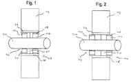
- FIG. 1 a schematic representation of a fire protection element 10 according to the invention is shown within a wall 12.
- a fire protection element 10 is attached to both sides of the wall 12, so that they form a fire protection device 14.
- the fire protection element 10 comprises a fire protection insert 16 and a carrier 18, to which the fire protection insert 16 is connected, and a heat-activatable drive means 20 for the fire protection insert 16.
- the fire protection insert 16 and the carrier 18 are closer to those pointing out of the wall 12 Ends of the opening 22 arranged as the heat-activatable drive means 20.
- the fire protection insert 16 is held by low-melting holding elements 24 within the wall 12.
- a housing 26 surrounds the fire protection insert 16 and the heat-activatable drive means 20.
- the housing 26 is shown as a continuous cladding tube 28 which surrounds both fire protection elements 10. In principle, however, one housing 26 per fire protection element 10 could also be provided, which lie flush against one another.
- a pipe 30 is guided through the opening 22 in the wall 12.
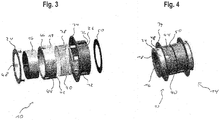
- Figure 2 is the same arrangement as in Figure 1 , but shown in the use position of the fire protection element 10.
- the holding elements 24 have melted away, as a result of which the heat-activatable drive means 20 has partially moved the fire protection insert 16 with the carrier 18 in front of the wall 12.
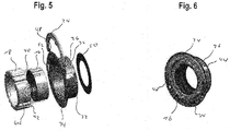
- FIG. 3 An exploded view of an embodiment of a fire protection element 10 according to the invention is shown.
- a cylindrical housing 26 which is open at both ends has a plurality of cutouts 32 on its outer surface, a circumferential collar 34 at one axial end and a circumferential groove 36 at the other axial end.
- the collar 34 projects radially outward beyond the inner diameter of the housing 26, so that the housing 26 can be fastened by means of the collar 34, for example on the outside of the wall 12 or on a formwork for casting the wall 12.
- the circumferential groove 36 runs within a radially inwardly projecting shoulder of the housing 26.
- a spring 40 which is arranged with its one axial end inside the groove 36 of the housing 26, serves as the drive element 38 of the heat-activatable drive means 20.
- the tongue 40 is supported on the carrier 18.
- the carrier 18 can have an annular groove 42 on one side, in which the spring 40 is received.
- the carrier 18 has on its outside at least one projection 44, which can engage in the cutouts 32 of the housing 26, and thus prevents the carrier 18 from the spring 40 completely, out of the housing 26, beyond the use position of the fire protection insert 16 can be pushed out.
- the carrier 18 On the end of the carrier 18 opposite the spring 40, the latter has three holding cutouts 46 distributed over the circumference of the carrier 18. A single one Retaining recess 46 would also suffice, but a more stable arrangement of the fire protection element 10 is achieved by means of several retaining recesses 46.
- the fire protection insert 16 can be used within the carrier 18.
- the fire protection insert 16 can consist of various fire protection materials, particularly preferably of an intumescent material, for example expanded graphite, which increases its volume in the event of a fire and thereby closes the opening 22.
- An annular holding element 24 with a plurality of axially projecting tongues 48 is placed on the carrier 18.
- the tongues 48 are received within the holding recesses 46 of the carrier 18 and have radially outwardly projecting lugs.
- the lugs each engage in a recess 32 of the housing 26 and thus hold the carrier 18 in the housing 26, while the spring 40 compressed by the carrier 18 is under prestress.
- the projection 44 of the carrier 18 can be in the same recess 32 as the lugs of the tongues 48 or, as in FIG Figure 4 can be seen in a separate recess 32.
- the annular holding element 24 can be fixed on the carrier 18, for example by gluing.
- At least the tongues 48 consist of a low-melting material, for example a low-melting alloy such as a soft solder or a plastic, and therefore melt away early in the event of a fire due to the heat input.
- a low-melting material for example a low-melting alloy such as a soft solder or a plastic
- the entire holding element 24 can also be made from a low-melting material.
- the fire protection element 10 comprises a smoke protection seal 50 which is arranged on the side of the housing 26 opposite the holding element 24 and in the event of a fire prevents the spread of smoke over the sides of the fire protection element 10.
- FIG 4 10 is a perspective view of a fire protection device 14 comprising two fire protection elements 10 and 10 'according to FIG Figure 3 , shown.
- the two fire protection elements 10 and 10 ' are arranged essentially symmetrically to the center of the fire protection device 14, the two housings 26 and 26' being mounted rotated relative to one another. Is between the two fire protection elements 10 and 10 ' the smoke protection seal 50 is attached so that only one smoke protection seal 50 is required for both fire protection elements 10 and 10 '.
- the projection 44 of the carrier 18 is guided within the recess 32 of the housing 26. In the event of a fire, this prevents the carrier 18 from moving out of the opening 22 in an uncontrolled manner, since the projections 44 can be moved as far as possible up to the collar 34 of the housing 26.
- the tongues 48 of the holding element 24 lie within the holding recesses 46. If the carrier 18 is now moved to the center of the fire protection device 14, the spring 40 is compressed. The lugs of the tongues 48 snap into the cutouts 32 in the housing 26. As a result, the spring 40 is preloaded and the fire protection insert 16 is held in its starting position within the fire protection element 10.
- the tongues 48 consist of a low-melting material, for example low-melting plastic or a soft solder, at least the lugs of the tongues 48 melt away in the event of a fire. As a result, the spring 40 relaxes and pushes the carrier 18 out of the housing 26 out of the wall 12. The fire protection insert 16 is thus moved into its use position in front of the wall and can then be activated by the action of heat.
- the housing 26 has a plurality of tabs 52 on the collar 34.
- the holding element 24 is designed as an arc, the ends of which engage in the tabs 52 on the collar 34 of the housing 26.
- the tongues 48 point radially inwards starting from the holding element 24 and thus hold the carrier 18 within the housing 26.
- the springs 40 are prestressed by the carrier 18 inserted into the housing 26.
- the tongues 48 melt away, as a result of which the support 18 together with the fire protection insert 16 received by the support 18 is pressed out of the wall 12 by the springs 40 and the fire protection insert 16 is moved into its use position. Since in this embodiment there are several, independently of one another drive elements 38 in the form of the springs 40, the carrier 18 and the fire protection insert 16 can be divided into several parts, for example halves, which can be moved out of the wall 12 independently of one another.
- the fire protection elements 10 shown can also have an additional cladding tube 28 which is arranged around the housing 26. This prevents the ingress of concrete when pouring the wall 12 and the ingress of dirt and moisture.
- a bimetal (not shown) can be used as the drive element 38 instead of the springs 40.
- the bimetal can be present, for example, as a band which bends under the influence of heat and thereby exerts a force on the carrier 18 and moves it together with the fire protection insert 16 out of the wall 12.
- a gas can be enclosed within an annular chamber, which expands under the action of heat and thereby presses the carrier 18 together with the fire protection insert 16 outwards.
Landscapes
- Health & Medical Sciences (AREA)
- Public Health (AREA)
- Business, Economics & Management (AREA)
- Emergency Management (AREA)
- Engineering & Computer Science (AREA)
- General Engineering & Computer Science (AREA)
- Mechanical Engineering (AREA)
- Building Environments (AREA)
Abstract
Ein Brandschutzelement zum Abdichten eines eine Öffnung (22) in einer Wand (12) oder Decke durchsetzenden brennbaren Körpers im Brandfall umfasst eine Brandschutzeinlage (16) und ein wärmeaktivierbares Antriebsmittel (20) für die Brandschutzeinlage (16), wobei sich die Brandschutzeinlage (16) in einer Ausgangsstellung innerhalb der Wand (12) oder Decke befindet und im Brandfall in eine Einsatzstellung bewegt wird, in welcher sich die Brandschutzeinlage (16) zumindest teilweise außerhalb der Wand (12) oder Decke befindet.
Description
- Die Erfindung betrifft ein Brandschutzelement zum Abdichten eines eine Öffnung in einer Wand oder Decke durchsetzenden brennbaren Körpers im Brandfall, sowie eine Brandschutzvorrichtung.
- Um eine Ausbreitung von Feuer oder Rauch in Gebäuden zu verhindern, müssen Öffnungen in Decken oder Wänden, in denen beispielsweise Rohre oder Kabel geführt werden, im Brandfall verschlossen werden können. Zu diesem Zweck werden verschiedene Brandschutzlösungen eingesetzt, zum Beispiel Bandagen oder Bänder, die in die Wand oder als Manschetten vor der Wand montiert werden.
- Dabei werden verschiedene Brandschutzmittel, beispielsweise in Form von Einlagen verwendet, die beispielsweise an einem Gehäuse befestigt werden. Insbesondere intumeszierende Materialien eignen sich für die Einlagen. Im Brandfall schäumt das intumeszierende Material durch Wärmeeinwirkung auf und verschließt die Öffnung, wodurch die Ausbreitung von Rauch oder Feuer verhindert oder zumindest verzögert wird.
- Brandschutzmanschetten haben den Vorteil, dass sie außerhalb der Wand montiert und so im Brandfall schneller erhitzt werden können, da das Brandschutzmittel nicht passiv durch die umgebende Wand gekühlt wird.
- Da die Manschetten jedoch an der Außenseite der Wand angebracht werden müssen, kann der Brandschutz erst installiert werden, nachdem die Wand oder Decke beispielsweise aus Beton bereits gegossen wurde und Rohre oder Kabelführungen verlegt worden sind. Dadurch sind zusätzliche Arbeitsschritte notwendig. Gleichzeitig besteht noch kein Brandschutz, bis die Manschetten montiert sind.
- Aus der
WO 2016 202 681 A1 ist ein Brandschutzband bekannt, das ein Intumeszenzmaterial auf einem Träger umfasst. Der Träger ist aus einem Material gebildet, welches sich selbstständig zu einer Spirale aufrollt, wenn keine gegenläufige Kraft auf das Material einwirkt. Das Brandschutzband wird beispielsweise um ein Rohr in einer Wand geklemmt und so unter Vorspannung gehalten. Im Brandfall schmilzt das Rohr weg, wodurch sich das Brandschutzband entrollt und auf diese Weise das Intumeszenzmaterial ins Innere der Öffnung innerhalb der Wand einträgt. - Die
WO 2004 015 319 A1 zeigt eine Manschette, in der in einem ringförmigen Gehäuse eine gespannte Schraubenfeder und ein hitzebeständiges Gewebe vorgesehen ist. Im Brandfall drückt die Schraubenfeder das schmelzende Rohr zusammen und zieht dabei das hitzebeständige Gewebe in das Innere der Rohröffnung mit. Zusätzlich ist ein Intumeszenzmaterial vorgesehen, welches zwischen einer Wand und der Schraubenfeder um das Rohr herum angeordnet ist und für einen weiteren Verschluss der Öffnung sorgt. - In der
DE 10 2004 014 347 B4 werden lamellenförmige Sperrelemente aus Bimetall eingesetzt, welche aufgerollt um das Rohr angeordnet sind und sich im Brandfall entrollen, um auf diese Weise die Öffnung irisartig zu verschließen. - Aus der
US 2017 009 470 A1 sind Rohrdurchführungen bekannt, die flexibel an die Dicke einer Wand oder Decke angepasst und bereits während des Gießens der Wand oder Decke montiert werden können. Jedoch weisen diese Rohrdurchführungen keine Brandschutzfunktion auf. - Aufgabe der Erfindung ist es, eine Brandschutzlösung bereitzustellen, die bereits während der Herstellung einer Wand oder Decke angebracht und im Brandfall frühzeitig aktiviert werden kann.
- Die Aufgabe wird erfindungsgemäß gelöst durch ein Brandschutzelement zum Abdichten eines eine Öffnung in einer Wand oder Decke durchsetzenden brennbaren Körpers im Brandfall, das eine Brandschutzeinlage und ein wärmeaktivierbares Antriebsmittel für die Brandschutzeinlage umfasst, wobei sich die Brandschutzeinlage in einer Ausgangsstellung innerhalb der Wand oder Decke befindet und im Brandfall durch das wärmeaktivierbare Antriebsmittel in eine Einsatzstellung bewegt wird, in welcher sich die Brandschutzeinlage zumindest teilweise außerhalb der Wand oder Decke befindet.
- Auf diese Weise wird erreicht, dass das Brandschutzelement zunächst innerhalb der Wand oder Decke angebracht werden kann, beispielsweise als Cast-in während des Gießens der Wand oder Decke mit Beton, und gleichzeitig die Brandschutzeinlage des Brandschutzelements im Brandfall vor die Wand bewegt werden kann. Somit wird das Brandschutzmaterial der Brandschutzeinlage nicht durch eine umgebende Wand oder Decke verdeckt und/oder gekühlt, wodurch eine frühzeitige Aktivierung und damit ein zuverlässiger Verschluss der Öffnung im Brandfall ermöglicht wird.
- Gleichzeitig muss das Brandschutzelement nicht von vornherein als Manschette vor der Wand montiert werden, wodurch das Brandschutzelement auch in begrenzten Platzverhältnissen angebracht werden kann und nicht von außen sichtbar ist.
- Auch eignen sich verschiedene Brandschutzmaterialien für die Brandschutzeinlage, sodass das Brandschutzelement für eine Vielzahl von Anwendungsfällen genutzt werden kann, beispielsweise auch für Leerrohre oder Kabeldurchführungen.
- Das wärmeaktivierbare Antriebsmittel kann eine Feder, ein Bimetall und/oder ein expandierbares Gas als Antriebselement umfassen. Federn stellen ein besonders kostengünstiges Antriebselement dar, während ein Bimetall und ein expandierbares Gas für eine konstante Krafteinwirkung eingesetzt werden können.
- In einer bevorzugten Ausführungsform umfasst das wärmeaktivierbare Antriebsmittel ein Gehäuse sowie ein mit dem Gehäuse verbundenes Halteelement und mindestens eine im Gehäuse angeordnete Feder, wobei das Halteelement in der Ausgangsstellung die Feder unter Vorspannung hält und bei Wärmeeinwirkung die Feder freigibt. Durch die vorgespannte Feder wird im Brandfall, sobald das Halteelement nachgibt, schlagartig eine große Kraft auf die Brandschutzeinlage aufgebracht. Dies ermöglicht es zuverlässig, die Brandschutzeinlage innerhalb kürzester Zeit aus der Wand oder Decke heraus in die Einsatzstellung zu bewegen.
- Das Gehäuse kann auch aus mehreren Gehäuseteilen bestehen, wobei ein erstes Gehäuseteil mit dem Halteelement in Verbindung steht und ein zweites Gehäuseteil, beispielsweise als Hüllrohr, um das Brandschutzelement herum angeordnet ist. Eine solche Anordnung verhindert ein Eindringen von Beton in das Brandschutzelement, wenn dieses bereits vor dem Gießen der Wand oder Decke, beispielsweise auf einer Schalung, angebracht wird. Zusätzlich verhindert eine solche Ausführungsform das Eindringen von Feuchtigkeit oder Schmutz nach dem Fertigstellen der Wand oder Decke.
- Das Halteelement kann zumindest teilweise aus einem niedrigschmelzenden Material bestehen, bevorzugt aus einem niedrigschmelzenden Kunststoff oder aus Weichlot, wie beispielsweise Lötzinn. Auf diese Weise kann sichergestellt werden, dass die Brandschutzeinlage bei einer durch den Erweichungspunkt des Halteelements vorbestimmten Temperatur frühzeitig in die Einsatzstellung übergeht und so eine frühe Aktivierung gewährleistet ist.
- Bevorzugt umfasst das wärmeaktivierbare Antriebsmittel einen Träger, auf dem die Brandschutzeinlage gelagert ist. Über den Träger kann eine stabile Verbindung zwischen der Brandschutzeinlage und dem wärmeaktivierbaren Antriebsmittel gewährleistet werden. Zugleich muss das Antriebselement nicht direkt auf die Brandschutzeinlage einwirken, sondern kann die Brandschutzeinlage auch durch eine Bewegung des Trägers verschieben. Dadurch kann die Brandschutzeinlage dünner gefertigt werden, da sie selbst keine Kontaktfläche zum Antriebselement aufweisen muss. Zugleich kann der Träger, beispielsweise durch Aussparungen, so ausgestaltet sein, das eine gute Kraftübertragung und eine stabile Verbindung zum Antriebselement gewährleistet ist.
- Die Brandschutzeinlage kann ein Brandschutzmaterial aufweisen, ausgewählt aus der Gruppe bestehend aus intumeszierenden Materialien, insbesondere Blähgraphit, Brandschutzbeschichtungen, Brandschutzschäumen, insbesondere auf Polyurethanbasis, und Ablationsbeschichtungen, insbesondere Aluminiumtrihydrat, und aus Kombinationen davon. Entsprechend kann das für eine bestimmte Anforderung am besten geeignete Brandschutzmaterial ausgewählt werden. Das Brandschutzelement kann daher für eine Vielzahl von Anwendungsfällen eingesetzt werden. Es ist auch denkbar, dass das Brandschutzelement erst vor Ort zusammengesetzt und mit der gewünschten Brandschutzeinlage versehen wird. Somit müssen zwar noch verschiedene Brandschutzeinlagen, aber lediglich ein Mechanismus vorgehalten werden.
- Um die Ausbreitung von Rauch im Brandfall zu verhindern, kann das Brandschutzelement zusätzlich eine Rauchschutzdichtung, bevorzugt aus Gummi oder einem Elastomer, umfassen. Die Rauchschutzdichtung wird dabei vorteilhafterweise an einem der Brandschutzeinlage entgegengesetzten Ende des Brandschutzelements angebracht, beispielsweise in einer Aussparung des Gehäuses, um eine zweite Barriere gegen Rauch hinter dem eigentlichen Brandschutzmaterial zu bilden.
- In einer bevorzugten Ausführungsform ist die Brandschutzeinlage und das wärmeaktivierbare Antriebsmittel jeweils aus mehreren Teilen aufgebaut, bevorzugt aus zwei bis vier Teilen, sodass die Teile der Brandschutzeinlage unabhängig voneinander von der Ausgangsstellung in die Einsatzstellung bewegt werden können. Auf diese Weise wird verhindert, dass die Brandschutzeinlage beispielsweise durch Unebenheiten oder Reste des brennbaren Körpers blockiert wird und im Brandfall nicht aus der Wand oder Decke ausfährt. Wenn die Brandschutzeinlage aus mehreren Teilen besteht, wird gewährleistet, dass zumindest eines der Teile im Brandfall vor der Wand liegt und so frühzeitig zumindest für einen Teilverschluss der Öffnung sorgt. Die in der Wand blockierten Teile können anschließend, später ausgelöst, für einen vollständigen Verschluss innerhalb der Wand oder Decke sorgen.
- Auch können die einzelnen Teile in dieser Ausführungsform entsprechend von mehreren niedrigschmelzenden Halteelementen in ihrer Ausgangsstellung gehalten werden. Dadurch wird es möglich, dass einige der Halteelemente früher schmelzen als andere und zumindest ein Teil der Brandschutzeinlage bereits vor die Wand oder Decke bewegt und so früher aktiviert wird.
- Besonders vorteilhaft ist es, wenn das Brandschutzelement in der Ausgangsstellung der Brandschutzeinlage bündig mit der Wand oder Decke abschließt. Auf diese Weise kann das Brandschutzelement direkt, beispielsweise als Cast-In auf einer Schalung vor dem Gießen der Wand oder Decke, montiert werden. Gleichzeitig ist dadurch bereits ab dem Zeitpunkt, an dem die Wand oder Decke gegossen wird, einsatzfähiger Brandschutz installiert. Auch benötigt das Brandschutzelement, außer im Brandfall, keinen Platz vor der Wand, wodurch eine Anwendung auch in engen Platzverhältnissen ermöglicht wird.
- Des Weiteren wird die Aufgabe erfindungsgemäß gelöst durch eine Brandschutzvorrichtung, umfassend zwei Brandschutzelemente der zuvor beschriebenen Art, dadurch gekennzeichnet, dass die beiden Brandschutzelemente symmetrisch zur Mitte der Öffnung der Wand oder Decke angeordnet sind. Eine solche Brandschutzvorrichtung hat den Vorteil, dass sie aus zwei identischen Brandschutzelementen zusammengesetzt werden kann, sodass für verschiedene Anwendungsfälle nur noch ein Brandschutzelement vorgehalten werden muss. Gleichzeitig ist gewährleistet, dass die Brandschutzeinlagen der beiden Brandschutzelemente jeweils auf einer Seite der Wand oder Decke vor diese bewegt werden können.
- Weitere Vorteile und Eigenschaften der Erfindung ergeben sich aus der nachfolgenden Beschreibung bevorzugter Ausführungsformen und den Zeichnungen, auf die Bezug genommen wird. Diese sollen nicht in einem einschränkenden Sinn verstanden werden. In den Zeichnungen zeigen:
-
Figur 1 eine schematische Darstellung eines erfindungsgemäßen Brandschutzelements in der Ausgangsstellung der Brandschutzeinlage, -
Figur 2 das Brandschutzelement ausFigur 1 in der Einsatzstellung der Brandschutzeinlage, -
Figur 3 eine Explosionsansicht einer ersten Ausführungsform des Brandschutzelements, -
Figur 4 eine perspektivische Darstellung eines Brandschutzelements nachFigur 3 , -
Figur 5 eine Explosionsansicht einer zweiten Ausführungsform des Brandschutzelements, und -
Figur 6 eine perspektivische Darstellung eines Brandschutzelements nachFigur 5 . - In
Figur 1 ist eine schematische Darstellung eines erfindungsgemäßen Brandschutzelements 10 innerhalb einer Wand 12 gezeigt. In der dargestellten Ausführungsform ist an beiden Seiten der Wand 12 jeweils ein Brandschutzelement 10 angebracht, sodass diese eine Brandschutzvorrichtung 14 bilden. - Das Brandschutzelement 10 umfasst eine Brandschutzeinlage 16 sowie einen Träger 18, mit dem die Brandschutzeinlage 16 verbunden ist, und ein wärmeaktivierbares Antriebsmittel 20 für die Brandschutzeinlage 16. Die Brandschutzeinlage 16 und der Träger 18 sind in der dargestellten Ausführungsform näher an den aus der Wand 12 weisenden Enden der Öffnung 22 als das wärmeaktivierbare Antriebsmittel 20 angeordnet.
- Die Brandschutzeinlage 16 wird von niedrigschmelzenden Halteelementen 24 innerhalb der Wand 12 gehalten. Ein Gehäuse 26 umgibt die Brandschutzeinlage 16 und das wärmeaktivierbare Antriebsmittel 20. In der dargestellten Ausführungsform ist das Gehäuse 26 als ein durchgängiges Hüllrohr 28 gezeigt, das beide Brandschutzelemente 10 umgibt. Grundsätzlich könnte jedoch auch jeweils ein Gehäuse 26 pro Brandschutzelement 10 vorgesehen sein, die bündig aneinander anliegen. Innerhalb des Brandschutzelements 10 ist ein Rohr 30 durch die Öffnung 22 in der Wand 12 geführt.
- In
Figur 2 ist die gleiche Anordnung wie inFigur 1 , jedoch in der Einsatzstellung des Brandschutzelements 10, gezeigt. Die Halteelemente 24 sind weggeschmolzen, wodurch das wärmeaktivierbare Antriebsmittel 20 die Brandschutzeinlage 16 mit dem Träger 18 teilweise vor die Wand 12 bewegt hat. - In
Figur 3 ist eine Explosionsansicht einer Ausführungsform eines erfindungsgemäßen Brandschutzelements 10 gezeigt. Ein an beiden Enden offenes zylinderförmiges Gehäuse 26 weist an seiner Mantelfläche mehrere Aussparungen 32, an einem axialen Ende einen umlaufenden Kragen 34 sowie am anderen axialen Ende eine umlaufende Nut 36 auf. Der Kragen 34 ragt radial nach außen über den inneren Durchmesser des Gehäuses 26 hinaus, sodass das Gehäuse 26 mittels des Kragens 34 beispielsweise auf der Außenseite der Wand 12 oder auf einer Schalung zum Gießen der Wand 12 befestigt werden kann. Die umlaufende Nut 36 verläuft innerhalb einer radial nach innen ragenden Schulter des Gehäuses 26. - Als Antriebselement 38 des wärmeaktivierbaren Antriebsmittels 20 dient eine Feder 40, die mit ihrem einen axialen Ende innerhalb der Nut 36 des Gehäuses 26 angeordnet ist. Am der Nut 36 entgegengesetzten axialen Ende der Feder 40 ist diese auf dem Träger 18 gelagert. Der Träger 18 kann auf einer Seite eine ringförmige Nut 42 aufweisen, in der die Feder 40 aufgenommen wird.
- Der Träger 18 weist an seiner Außenseite zumindest einen Vorsprung 44 auf, welcher in die Aussparungen 32 des Gehäuses 26 eingreifen kann, und somit verhindert, dass der Träger 18 von der Feder 40 komplett, über die Einsatzstellung der Brandschutzeinlage 16 hinaus, aus dem Gehäuse 26 herausgedrückt werden kann.
- Auf dem der Feder 40 entgegengesetzten Ende des Trägers 18 weist dieser drei über den Umfang des Trägers 18 verteilte Halteaussparungen 46 auf. Eine einzelne Halteaussparung 46 würde ebenfalls ausreichen, durch mehrere Halteaussparungen 46 wird jedoch eine stabilere Anordnung des Brandschutzelements 10 erreicht.
- Eine ringförmige Brandschutzeinlage 16 kann innerhalb des Trägers 18 eingesetzt werden. Die Brandschutzeinlage 16 kann aus verschiedenen Brandschutzmaterialien bestehen, besonders bevorzugt aus einen intumeszierenden Material, beispielsweise Blähgraphit, das im Brandfall sein Volumen vergrößert und die Öffnung 22 dadurch verschließt.
- Auf den Träger 18 wird ein ringförmiges Halteelement 24 mit mehreren axial abstehenden Zungen 48 aufgesetzt. Die Zungen 48 werden dabei innerhalb der Halteaussparungen 46 des Trägers 18 aufgenommen und weisen radial nach außenstehende Nasen auf. Die Nasen greifen jeweils in eine Aussparung 32 des Gehäuses 26 ein und halten damit den Träger 18 im Gehäuse 26, während die vom Träger 18 zusammengedrückte Feder 40 unter Vorspannung steht. Der Vorsprung 44 des Trägers 18 kann in derselben Aussparung 32 wie die Nasen der Zungen 48 oder, wie in
Figur 4 zu sehen, in einer separaten Aussparung 32 geführt sein. Das ringförmige Halteelement 24 kann auf dem Träger 18 fixiert werden, beispielsweise durch Verkleben. - Zumindest die Zungen 48 bestehen aus einem niedrig schmelzenden Material, beispielsweise einer niedrigschmelzenden Legierung wie einem Weichlot oder einem Kunststoff, und schmelzen daher im Brandfall durch den Wärmeeintrag frühzeitig weg. Grundsätzlich kann jedoch auch das gesamte Halteelement 24 aus einem niedrig schmelzenden Material gefertigt sein.
- Zusätzlich umfasst das Brandschutzelement 10 eine Rauchschutzdichtung 50, welche auf der dem Halteelement 24 entgegengesetzten Seite des Gehäuses 26 angeordnet ist und im Brandfall die Ausbreitung von Rauch über die Seiten des Brandschutzelements 10 verhindert.
- In
Figur 4 ist eine perspektivische Ansicht einer Brandschutzvorrichtung 14, umfassend zwei Brandschutzelemente 10 und 10' gemäßFigur 3 , gezeigt. Die beiden Brandschutzelemente 10 und 10' sind im Wesentlichen symmetrisch zur Mitte der Brandschutzvorrichtung 14 angeordnet, wobei beide Gehäuse 26 und 26' zueinander verdreht angebracht sind. Zwischen den beiden Brandschutzelementen 10 und 10' ist die Rauchschutzdichtung 50 angebracht, sodass nur eine Rauchschutzdichtung 50 für beide Brandschutzelemente 10 und 10' benötigt wird. - Der Vorsprung 44 des Trägers 18 ist innerhalb der Aussparung 32 des Gehäuses 26 geführt. Dadurch wird im Brandfall ein unkontrolliertes Ausfahren des Trägers 18 aus der Öffnung 22 verhindert, da die Vorsprünge 44 maximal bis zum Kragen 34 des Gehäuses 26 bewegt werden können.
- Die Zungen 48 des Halteelements 24 liegen innerhalb der Halteaussparungen 46. Wird nun der Träger 18 zur Mitte der Brandschutzvorrichtung 14 bewegt, wird die Feder 40 zusammengedrückt. Dabei rasten die Nasen der Zungen 48 in den Aussparungen 32 des Gehäuses 26 ein. Dadurch wird die Feder 40 vorgespannt und die Brandschutzeinlage 16 innerhalb des Brandschutzelements 10 in ihrer Ausgangsstellung gehalten.
- Da die Zungen 48 aus einem niedrig schmelzenden Material, beispielsweise niedrig schmelzendem Kunststoff oder einem Weichlot, bestehen, schmelzen zumindest die Nasen der Zungen 48 im Brandfall weg. Dadurch entspannt sich die Feder 40 und drückt den Träger 18 aus dem Gehäuse 26 aus der Wand 12 heraus. Die Brandschutzeinlage 16 wird somit in ihre Einsatzstellung vor die Wand bewegt und kann anschließend durch die Wärmeeinwirkung aktiviert werden.
- In den
Figuren 5 und 6 ist eine alternative Ausführungsform des Brandschutzelements 10 gezeigt. In dieser werden vier Federn 40 als Antriebselement 38 eingesetzt, welche jeweils in ringförmige Nuten 42 des Trägers 18 eingreifen. An ihrem anderen Ende stützen sich die Federn 40 innerhalb der umlaufenden Nut 36 des Gehäuses 26 ab. - Das Gehäuse 26 weist in dieser Ausführungsform auf dem Kragen 34 mehrere Laschen 52 auf. Das Halteelement 24 ist als Bogen ausgeführt, dessen Enden in die Laschen 52 auf dem Kragen 34 des Gehäuses 26 eingreifen. Die Zungen 48 zeigen ausgehend vom Halteelement 24 radial nach innen und halten so den Träger 18 innerhalb des Gehäuses 26. Die Federn 40 werden durch den in das Gehäuse 26 eingeführten Träger 18 vorgespannt.
- Im Brandfall schmelzen die Zungen 48 weg, wodurch der Träger 18 zusammen mit der vom Träger 18 aufgenommenen Brandschutzeinlage 16 durch die Federn 40 aus der Wand 12 gedrückt und die Brandschutzeinlage 16 in ihre Einsatzstellung bewegt wird. Da in dieser Ausführungsform in Form der Federn 40 mehrere, voneinander unabhängige Antriebselemente 38 vorliegen, können der Träger 18 und die Brandschutzeinlage 16 in mehrere Teile, beispielsweise Hälften, aufgeteilt sein, die unabhängig voneinander aus der Wand 12 herausgefahren werden können.
- Die in den
Figuren 3 bis 6 gezeigten Brandschutzelemente 10 können neben dem gezeigten Gehäuse 26 noch ein zusätzliches Hüllrohr 28 aufweisen, welches um das Gehäuses 26 herum angeordnet ist. Dadurch wird das Eindringen von Beton beim Gießen der Wand 12 sowie das Eindringen von Schmutz und Feuchtigkeit verhindert. - In einer alternativen Ausführungsform kann statt der Federn 40 ein Bimetall (nicht gezeigt) als Antriebselement 38 genutzt werden. Dabei kann das Bimetall beispielsweise als Band vorliegen, welches sich unter Wärmeeinwirkung verbiegt und dadurch eine Kraft auf den Träger 18 ausübt und diesen zusammen mit der Brandschutzeinlage 16 aus der Wand 12 bewegt.
- In einer weiteren alternativen Ausführungsform kann innerhalb einer ringförmigen Kammer ein Gas eingeschlossen sein, welches unter Wärmeeinwirkung expandiert und dadurch den Träger 18 zusammen mit der Brandschutzeinlage 16 nach außen drückt.
Claims (14)
- Brandschutzelement zum Abdichten eines eine Öffnung (22) in einer Wand (12) oder Decke durchsetzenden brennbaren Körpers im Brandfall, mit einer Brandschutzeinlage (16) und einem wärmeaktivierbaren Antriebsmittel (20) für die Brandschutzeinlage (16), wobei sich die Brandschutzeinlage (16) in einer Ausgangsstellung innerhalb der Wand (12) oder Decke befindet und im Brandfall durch das wärmeaktivierbare Antriebsmittel (20) in eine Einsatzstellung bewegt wird, in welcher sich die Brandschutzeinlage (16) zumindest teilweise außerhalb der Wand (12) oder Decke befindet.
- Brandschutzelement nach Anspruch 1, dadurch gekennzeichnet, dass das wärmeaktivierbare Antriebsmittel (20) eine Feder (40), ein Bimetall und/oder ein expandierbares Gas als Antriebselement (38) umfasst.
- Brandschutzelement nach einem der vorherigen Ansprüche, dadurch gekennzeichnet, dass das wärmeaktivierbare Antriebsmittel (20) ein Gehäuse (26) sowie ein mit dem Gehäuse (26) verbundenes Halteelement (24) und mindestens eine im Gehäuse (26) angeordnete Feder (40) umfasst, wobei das Halteelement (24) in der Ausgangsstellung die Feder (40) unter Vorspannung hält.
- Brandschutzelement nach Anspruch 3, dadurch gekennzeichnet, dass das Halteelement (24) zumindest teilweise aus einem niedrig schmelzenden Material besteht, bevorzugt aus einem niedrig schmelzenden Kunststoff oder aus einem Weichlot.
- Brandschutzelement nach einem der vorherigen Ansprüche, dadurch gekennzeichnet, dass das wärmeaktivierbare Antriebsmittel (20) einen Träger (18) umfasst, auf dem die Brandschutzeinlage (16) gelagert ist.
- Brandschutzelement nach Anspruch 5, dadurch gekennzeichnet, dass das Haltelement (24) axial oder radial abstehende Zungen (48) aufweist, die den Träger (18) in der Ausgangstellung im Gehäuse (26) halten.
- Brandschutzelement nach Anspruch 6, dadurch gekennzeichnet, dass das Gehäuse (26) eine oder mehrere Aussparungen (32) oder Laschen (52) aufweist, in welche die Zungen (48) eingreifen.
- Brandschutzelement nach einem der Ansprüche 5 bis 7, dadurch gekennzeichnet, dass der Träger (18) mit mindestens einer im Gehäuse (26) angeordneten Feder (40) zusammenwirkt und die Feder (40) in der Ausgangsstellung unter Vorspannung hält.
- Brandschutzelement nach einem der Ansprüche 5 bis 8, dadurch gekennzeichnet, dass am Träger (18) mindestens ein Vorsprung (44) vorgesehen ist, und dass das Gehäuse (26) wenigstens eine Aussparung (32) aufweist, in welcher der Vorsprung (44) geführt ist, wobei der Vorsprung (44) den Träger (18) im Gehäuse (26) hält, wenn die Brandschutzeinlage (16) in die Einsatzstellung bewegt wird.
- Brandschutzelement nach einem der vorherigen Ansprüche, dadurch gekennzeichnet, dass die Brandschutzeinlage (16) ein Brandschutzmaterial aufweist, ausgewählt aus der Gruppe bestehend aus intumeszierenden Materialien, insbesondere Blähgraphit, Brandschutzbeschichtungen, Brandschutzschäumen, insbesondere auf Basis von Polyurethan-Schaum, und Ablationsbeschichtungen.
- Brandschutzelement nach einem der vorherigen Ansprüche, dadurch gekennzeichnet, dass das Brandschutzelement (10) zusätzlich eine Rauchschutzdichtung (50), bevorzugt aus Gummi, umfasst.
- Brandschutzelement nach einem der vorherigen Ansprüche, dadurch gekennzeichnet, dass die Brandschutzeinlage (16) und das wärmeaktivierbare Antriebsmittel (20) jeweils aus mehreren Teilen aufgebaut sind, bevorzugt aus zwei bis vier Teilen, sodass die Teile der Brandschutzeinlage (16) unabhängig voneinander von der Ausgangsstellung in die Einsatzstellung bewegt werden können.
- Brandschutzelement nach einem der vorherigen Ansprüche, dadurch gekennzeichnet, dass das Brandschutzelement (10) in der Ausgangsstellung der Brandschutzeinlage (16) bündig mit der Wand (12) oder Decke abschließt.
- Brandschutzvorrichtung, umfassend zwei Brandschutzelemente (10, 10') nach einem der vorherigen Ansprüche, dadurch gekennzeichnet, dass die beiden Brandschutzelemente (10, 10') symmetrisch zur Mitte der Öffnung (22) der Wand (12) oder Decke angeordnet sind.
Priority Applications (4)
| Application Number | Priority Date | Filing Date | Title |
|---|---|---|---|
| EP18211203.7A EP3666342A1 (de) | 2018-12-10 | 2018-12-10 | Brandschutzelement |
| EP19809056.5A EP3894020A1 (de) | 2018-12-10 | 2019-11-22 | Brandschutzelement |
| US17/309,410 US11850455B2 (en) | 2018-12-10 | 2019-11-22 | Fire protection element |
| PCT/EP2019/082292 WO2020120108A1 (de) | 2018-12-10 | 2019-11-22 | Brandschutzelement |
Applications Claiming Priority (1)
| Application Number | Priority Date | Filing Date | Title |
|---|---|---|---|
| EP18211203.7A EP3666342A1 (de) | 2018-12-10 | 2018-12-10 | Brandschutzelement |
Publications (1)
| Publication Number | Publication Date |
|---|---|
| EP3666342A1 true EP3666342A1 (de) | 2020-06-17 |
Family
ID=64664081
Family Applications (2)
| Application Number | Title | Priority Date | Filing Date |
|---|---|---|---|
| EP18211203.7A Withdrawn EP3666342A1 (de) | 2018-12-10 | 2018-12-10 | Brandschutzelement |
| EP19809056.5A Pending EP3894020A1 (de) | 2018-12-10 | 2019-11-22 | Brandschutzelement |
Family Applications After (1)
| Application Number | Title | Priority Date | Filing Date |
|---|---|---|---|
| EP19809056.5A Pending EP3894020A1 (de) | 2018-12-10 | 2019-11-22 | Brandschutzelement |
Country Status (3)
| Country | Link |
|---|---|
| US (1) | US11850455B2 (de) |
| EP (2) | EP3666342A1 (de) |
| WO (1) | WO2020120108A1 (de) |
Citations (7)
| Publication number | Priority date | Publication date | Assignee | Title |
|---|---|---|---|---|
| GB2077382A (en) * | 1980-06-04 | 1981-12-16 | Stuart Anthony Rowland | Fire-resistant sleeves |
| DE20214256U1 (de) * | 2002-09-14 | 2002-11-28 | Rigips GmbH, 40549 Düsseldorf | Rohrmanschette |
| WO2004015319A1 (en) | 2002-08-09 | 2004-02-19 | Promat Australia Pty Ltd | Ring dampers for air-conditioning ducts |
| DE102004014347B4 (de) | 2004-03-24 | 2007-06-14 | Hilti Ag | Brandschutzmanschette |
| US20070193141A1 (en) * | 2006-01-31 | 2007-08-23 | Building Connections, Llc | Fire stop clamp |
| WO2016202681A1 (en) | 2015-06-19 | 2016-12-22 | Rockwool International A/S | Intumescent fire sleeve, coil of several intumescent fire sleeves and method for installation of an intumescent fire sleeve |
| US20170009470A1 (en) | 2014-01-23 | 2017-01-12 | Hauff-Technik Gmbh & Co. Kg | Use of a feed-through for installation in a wall or floor element |
Family Cites Families (2)
| Publication number | Priority date | Publication date | Assignee | Title |
|---|---|---|---|---|
| US8793947B2 (en) * | 2010-04-08 | 2014-08-05 | California Expanded Metal Products Company | Fire-rated wall construction product |
| NL2019583B1 (en) * | 2017-09-20 | 2019-03-28 | Beele Eng Bv | System and method for providing a conduit sealingly to a through-opening in a plate-shaped construction element |
-
2018
- 2018-12-10 EP EP18211203.7A patent/EP3666342A1/de not_active Withdrawn
-
2019
- 2019-11-22 WO PCT/EP2019/082292 patent/WO2020120108A1/de not_active Ceased
- 2019-11-22 EP EP19809056.5A patent/EP3894020A1/de active Pending
- 2019-11-22 US US17/309,410 patent/US11850455B2/en active Active
Patent Citations (7)
| Publication number | Priority date | Publication date | Assignee | Title |
|---|---|---|---|---|
| GB2077382A (en) * | 1980-06-04 | 1981-12-16 | Stuart Anthony Rowland | Fire-resistant sleeves |
| WO2004015319A1 (en) | 2002-08-09 | 2004-02-19 | Promat Australia Pty Ltd | Ring dampers for air-conditioning ducts |
| DE20214256U1 (de) * | 2002-09-14 | 2002-11-28 | Rigips GmbH, 40549 Düsseldorf | Rohrmanschette |
| DE102004014347B4 (de) | 2004-03-24 | 2007-06-14 | Hilti Ag | Brandschutzmanschette |
| US20070193141A1 (en) * | 2006-01-31 | 2007-08-23 | Building Connections, Llc | Fire stop clamp |
| US20170009470A1 (en) | 2014-01-23 | 2017-01-12 | Hauff-Technik Gmbh & Co. Kg | Use of a feed-through for installation in a wall or floor element |
| WO2016202681A1 (en) | 2015-06-19 | 2016-12-22 | Rockwool International A/S | Intumescent fire sleeve, coil of several intumescent fire sleeves and method for installation of an intumescent fire sleeve |
Also Published As
| Publication number | Publication date |
|---|---|
| US20220032098A1 (en) | 2022-02-03 |
| EP3894020A1 (de) | 2021-10-20 |
| US11850455B2 (en) | 2023-12-26 |
| WO2020120108A1 (de) | 2020-06-18 |
Similar Documents
| Publication | Publication Date | Title |
|---|---|---|
| EP4043080B1 (de) | Brandschutzmanschette | |
| EP2096346B1 (de) | Leitungsdurchführung zum Durchführen von Leitungen durch ein Bauteil | |
| EP2587106B1 (de) | Brandschutzmanschette | |
| EP2607761B1 (de) | Brandschutzmanschette | |
| EP2578273A2 (de) | Halter für eine Brandschutzmanschette und Verwendung dieses Halters | |
| DE19960485A1 (de) | Brandschutzmanschette für Rohre, Kabel u. dgl. | |
| DE19806012A1 (de) | Vorrichtung zur Erstellung einer feuerhemmenden Mauerdurchführung für Rohre, Kabel und dergleichen | |
| DE112006000687T5 (de) | Stopfen mit Klemmeinrichtung | |
| EP2273639B1 (de) | Elektrische Installationsdose | |
| EP3356715B1 (de) | Leitungsdurchführung zum durchführen von leitungen durch ein bauteil | |
| EP2853797A2 (de) | Brandschutzvorrichtung bei Übergang auf Kunststoffrohr | |
| EP0044468B1 (de) | Wärmeisoliertes Rohrleitungselement und Rohrleitungssystem aus diesen Rohrleitungselementen sowie Verfahren zur Herstellung des Rohrleitungselementes und des Rohrleitungssystems | |
| DE2947593C2 (de) | ||
| DE102004032869A1 (de) | Vorrichtung zum Abdichten einer Durchführung für Leitungen in einem Bauteil | |
| EP3282164A1 (de) | Rohrleitungssystem | |
| EP3567289B1 (de) | Brandschutzmanschette und verfahren zu ihrer herstellung | |
| EP3894020A1 (de) | Brandschutzelement | |
| EP3208507B1 (de) | Kabeldurchführungseinrichtung mit brandschutz | |
| DE202013002916U1 (de) | Brandschutzvorrichtung zum brandsicheren Abschotten einer Rohrverbindung | |
| DE102004055928B4 (de) | Brandschutzmanschette | |
| EP3885588A1 (de) | Isolierhülse | |
| WO2020120110A1 (de) | Brandschutzelement | |
| DE102015121031A1 (de) | Brandschutzeinrichtung | |
| DE3108921C2 (de) | Feuerschutz-Absperrvorrichtung für einen Luftkanal | |
| DE102014100371A1 (de) | Vorrichtung für die Durchführung einer Leitung durch eine Öffnung in einer Wand oder Decke |
Legal Events
| Date | Code | Title | Description |
|---|---|---|---|
| PUAI | Public reference made under article 153(3) epc to a published international application that has entered the european phase |
Free format text: ORIGINAL CODE: 0009012 |
|
| STAA | Information on the status of an ep patent application or granted ep patent |
Free format text: STATUS: THE APPLICATION HAS BEEN PUBLISHED |
|
| AK | Designated contracting states |
Kind code of ref document: A1 Designated state(s): AL AT BE BG CH CY CZ DE DK EE ES FI FR GB GR HR HU IE IS IT LI LT LU LV MC MK MT NL NO PL PT RO RS SE SI SK SM TR |
|
| AX | Request for extension of the european patent |
Extension state: BA ME |
|
| STAA | Information on the status of an ep patent application or granted ep patent |
Free format text: STATUS: THE APPLICATION IS DEEMED TO BE WITHDRAWN |
|
| 18D | Application deemed to be withdrawn |
Effective date: 20201218 |