EP3666194B1 - Couplage d'une sonde ultrasonore sans fil avec un système ultrasonore mobile - Google Patents
Couplage d'une sonde ultrasonore sans fil avec un système ultrasonore mobile Download PDFInfo
- Publication number
- EP3666194B1 EP3666194B1 EP20150926.2A EP20150926A EP3666194B1 EP 3666194 B1 EP3666194 B1 EP 3666194B1 EP 20150926 A EP20150926 A EP 20150926A EP 3666194 B1 EP3666194 B1 EP 3666194B1
- Authority
- EP
- European Patent Office
- Prior art keywords
- probe
- ultrasound system
- wireless
- mobile
- ultrasound
- Prior art date
- Legal status (The legal status is an assumption and is not a legal conclusion. Google has not performed a legal analysis and makes no representation as to the accuracy of the status listed.)
- Active
Links
- 239000000523 sample Substances 0.000 title claims description 216
- 238000002604 ultrasonography Methods 0.000 title claims description 140
- 238000004891 communication Methods 0.000 claims description 40
- 239000000725 suspension Substances 0.000 claims description 2
- 238000000034 method Methods 0.000 description 9
- 230000003750 conditioning effect Effects 0.000 description 4
- 230000010287 polarization Effects 0.000 description 4
- 230000008569 process Effects 0.000 description 4
- 230000005540 biological transmission Effects 0.000 description 3
- 238000010586 diagram Methods 0.000 description 3
- 238000003384 imaging method Methods 0.000 description 3
- 229920000642 polymer Polymers 0.000 description 3
- 230000009471 action Effects 0.000 description 2
- 230000000694 effects Effects 0.000 description 2
- 230000008054 signal transmission Effects 0.000 description 2
- 102100025283 Gap junction alpha-8 protein Human genes 0.000 description 1
- WHXSMMKQMYFTQS-UHFFFAOYSA-N Lithium Chemical group [Li] WHXSMMKQMYFTQS-UHFFFAOYSA-N 0.000 description 1
- 239000002033 PVDF binder Substances 0.000 description 1
- 230000004913 activation Effects 0.000 description 1
- 239000000919 ceramic Substances 0.000 description 1
- 230000008859 change Effects 0.000 description 1
- 230000000295 complement effect Effects 0.000 description 1
- 230000001934 delay Effects 0.000 description 1
- 230000001419 dependent effect Effects 0.000 description 1
- 238000011161 development Methods 0.000 description 1
- 238000002059 diagnostic imaging Methods 0.000 description 1
- 238000002592 echocardiography Methods 0.000 description 1
- 238000005516 engineering process Methods 0.000 description 1
- 230000010354 integration Effects 0.000 description 1
- 230000003993 interaction Effects 0.000 description 1
- 229910052744 lithium Inorganic materials 0.000 description 1
- 239000011159 matrix material Substances 0.000 description 1
- 239000012528 membrane Substances 0.000 description 1
- 238000004806 packaging method and process Methods 0.000 description 1
- 229920002981 polyvinylidene fluoride Polymers 0.000 description 1
- 238000012545 processing Methods 0.000 description 1
- 230000005855 radiation Effects 0.000 description 1
- 230000004044 response Effects 0.000 description 1
- 238000007789 sealing Methods 0.000 description 1
- 239000004065 semiconductor Substances 0.000 description 1
- 238000001228 spectrum Methods 0.000 description 1
- 238000012546 transfer Methods 0.000 description 1
Images

Classifications
-
- A—HUMAN NECESSITIES
- A61—MEDICAL OR VETERINARY SCIENCE; HYGIENE
- A61B—DIAGNOSIS; SURGERY; IDENTIFICATION
- A61B8/00—Diagnosis using ultrasonic, sonic or infrasonic waves
- A61B8/44—Constructional features of the ultrasonic, sonic or infrasonic diagnostic device
- A61B8/4444—Constructional features of the ultrasonic, sonic or infrasonic diagnostic device related to the probe
- A61B8/4472—Wireless probes
-
- A—HUMAN NECESSITIES
- A61—MEDICAL OR VETERINARY SCIENCE; HYGIENE
- A61B—DIAGNOSIS; SURGERY; IDENTIFICATION
- A61B8/00—Diagnosis using ultrasonic, sonic or infrasonic waves
- A61B8/44—Constructional features of the ultrasonic, sonic or infrasonic diagnostic device
- A61B8/4411—Device being modular
-
- A—HUMAN NECESSITIES
- A61—MEDICAL OR VETERINARY SCIENCE; HYGIENE
- A61B—DIAGNOSIS; SURGERY; IDENTIFICATION
- A61B8/00—Diagnosis using ultrasonic, sonic or infrasonic waves
- A61B8/44—Constructional features of the ultrasonic, sonic or infrasonic diagnostic device
- A61B8/4427—Device being portable or laptop-like
-
- G—PHYSICS
- G01—MEASURING; TESTING
- G01S—RADIO DIRECTION-FINDING; RADIO NAVIGATION; DETERMINING DISTANCE OR VELOCITY BY USE OF RADIO WAVES; LOCATING OR PRESENCE-DETECTING BY USE OF THE REFLECTION OR RERADIATION OF RADIO WAVES; ANALOGOUS ARRANGEMENTS USING OTHER WAVES
- G01S7/00—Details of systems according to groups G01S13/00, G01S15/00, G01S17/00
- G01S7/003—Transmission of data between radar, sonar or lidar systems and remote stations
-
- G—PHYSICS
- G01—MEASURING; TESTING
- G01S—RADIO DIRECTION-FINDING; RADIO NAVIGATION; DETERMINING DISTANCE OR VELOCITY BY USE OF RADIO WAVES; LOCATING OR PRESENCE-DETECTING BY USE OF THE REFLECTION OR RERADIATION OF RADIO WAVES; ANALOGOUS ARRANGEMENTS USING OTHER WAVES
- G01S7/00—Details of systems according to groups G01S13/00, G01S15/00, G01S17/00
- G01S7/52—Details of systems according to groups G01S13/00, G01S15/00, G01S17/00 of systems according to group G01S15/00
Definitions
- This invention relates to medical diagnostic ultrasound systems and, in particular, to the pairing of a wireless ultrasound probe with the desired ultrasound system.
- An ultrasound probe transmits ultrasound waves and receives ultrasonic echo signals with piezoelectric transducer elements that mechanically deflect when driven by a high voltage signal and convert vibrations due to received echo signals into electrical signals.
- ultrasound probes have been detachably connected to an ultrasound system by multiconductor cables which couple power and signals between the ultrasound system mainframe, which processes the echo signals into images, and the probe.
- these probe cables can be lengthy, extending upwards of three meters in length.
- numerous sonographers do not like the inconvenience of the probe cable, which can be heavy, become tangled, and drag on the floor and get run over by the wheels when the ultrasound cart is moved or repositioned.
- a wireless probe Before a wireless probe can be used to scan a patient, it must first be put into reliable two-way communication with the ultrasound system mainframe.
- a patent which has considered this step is US Pat. 8,656,783 (Randall et al. ), where this process is termed "linkup" as described in conjunction with Fig. 9 of the patent.
- This patent proposes to establish a communication link between a probe and an ultrasound system based upon the proximity of the two with each other and/or with other devices. For instance, if the probe and system are in proximity such that they are within r.f. range of each other, the communication link would be established. If there are multiple probes and/or systems within range, linkup would occur between the probe and system within closest proximity.
- the patent also proposes that the user may participate in the linkup by pressing a button to communicate a particular data sequence or character between the system and the probe to establish the linkup.
- the user may also select a desired probe type from a list of different types of probes, causing the system to send a linkup request to probes of the selected type.
- the patent goes on to say that the system and the probe may identify each other by their proximity (e.g., the linked probe is the one nearest the system), strength of signal communicated by the system (e.g., the probe links to the system sending the strongest signal), communication of a predetermined identifier, or the absence of any other probes. Once a communication link is established, it will endure for at least one operating session or over some predetermined period of time.
- US 2013/245451 discloses an ultrasonic diagnostic apparatus having multiple ultrasonic probes and an apparatus body.
- the probes are connected to the apparatus body and an interface unit controls switching between the multiple probes.
- Lights on the probes are controlled in dependence upon a connection state.
- US 2014/180110 discloses a system for pairing a wireless ultrasound probe and an ultrasound scanner via near field communication (NFC) connection.
- NFC near field communication
- US 2008/114241 similar to the afore-mentioned US Pat. 8,656,783 , discloses a method for establishing linkup between a probe and a main unit based on proximity between the two.
- the predetermined range is one meter, or the predetermined range is a distance of one meter from an antenna of the mobile ultrasound system radio.
- the ultrasound system radio and the wireless probe radio are both ultra wideband transceivers, such as WiFi (802.11) standard transceivers.
- the determining can further include receiving with the ultrasound system radio a radio signal from the wireless probe and producing a signal indicating the strength of the received signal.
- the determining can further include comparing the signal indicating the strength of the received signal to a threshold voltage.
- the producing can further include producing an RSSI signal by the ultrasound system radio.
- the threshold voltage is equal to a signal indicating the strength of the received signal when the wireless probe is at the predetermined distance from the ultrasound system.
- the system can be configured to maintain a communication link established by the pairing until the user affirmatively ends it; or the wireless ultrasound probe is turned off; or the wireless ultrasound probe has been out of range of the mobile ultrasound system for a long period of time; or the communication of new data over the link has been idle for a preset period of time.
- system can further comprise a user control to maintain the paired communication during suspension of the ultrasound exam.
- the pairing circuit is configured to locate a plurality of wireless ultrasound probes, each having a radio, within radio range of a mobile ultrasound system having a radio; to receive with the radio of the mobile ultrasound system, a unique identifier signal from each of the wireless ultrasound probes; and the system further comprises a display configured to display the identities of the wireless ultrasound probes in correspondence with the unique identifier signals; and the pairing circuit is configured to pair a particular wireless ultrasound probe and the mobile ultrasound system by selecting the displayed identity of the particular wireless ultrasound probe.
- the displaying can include displaying the identities of the wireless ultrasound probes in order of the strength of signals received from the probes, and/or the displaying can include displaying the identity of a wireless ultrasound probe only if it is within a predetermined distance of the mobile ultrasound system; and wherein pairing further comprises selecting the displayed wireless ultrasound probe for pairing.
- a wireless probe is paired to be in r.f. communication with a mobile ultrasound system when the probe is brought within a predetermined distance of the ultrasound system, as indicated by the received signal strength indication (RSSI) at the ultrasound system's radio.
- the radio type used by the probe and the ultrasound system can be ultra wideband (UWB) transceivers, WiFi (IEEE 802.11) transceivers, or transceivers of some other standard.
- the probe transmits an identifier which uniquely identifies that probe.
- the signal transmitted by the probe is calibrated to the predetermined distance so that, when the probe is at or closer than the predetermined distance with the ultrasound system, the RSSI received and measured at the system will be at or above a predetermined threshold.
- the system automatically selects the probe's unique transmitted identifier as the one with which to establish communication for an ultrasound procedure.
- the pairing process can be set to occur automatically when a wireless probe is brought within the predetermined range and the system is not currently in communication with another probe, or can be initiated by the user pressing a button on the system when a probe is within the predetermined range.
- the communication link is maintained until the user affirmatively ends it, or until the wireless probe is turned off, or until the wireless probe has been out of range of the ultrasound system for a long period of time, or for as long as data is being communicated over the link, or until after the communication of new data over the link has been idle for a preset period of time, i.e., the idle link times out.
- the user can select a wireless probe with which to pair from a list of probes on the display of the ultrasound system.
- the displayed list is a list of the probes currently found to be within r.f. communication range of the ultrasound system, and is preferably displayed on the screen in signal strength order, that is, the probe nearest to the system is at the top of the list.
- the user selects a probe to pair to the system and, if the probe is not presently linked to be in communication with another system, the communication link to that probe is established.
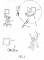
- FIGURE 1 depicts an ultrasound lab with four mobile ultrasound systems in it, a premium Epiq system 20, a midrange ClearVue system 30, a tablet style Visiq system 40, and a laptop style CX50 system 50, all made by Philips Healthcare of Andover, MA, USA.
- all of the ultrasound systems have wireless capability and so are able to work with wireless ultrasound probes.
- probe 10a which is being used with the laptop system 50
- probe 10b which is being used with the tablet system 40.
- the third probe 10c is in the process of being carried through the lab to be used with the premium system 20. As it does so in this example, it passes into close proximity with the laptop system 50.
- the in-transit probe 10c could pair with the laptop system 50 as it passes close to the antenna 54 of the laptop system's radio. This undesired pairing would disrupt the intended use of probe 10a with the laptop system 50, and illustrates a problem with proximity pairing which must be addressed.
- FIGURE 1 also illustrates a dashed circle 60 which in this example is marking the outer boundary of a spherical one meter distance from the radio antenna 54 of the laptop system 50.
- the problem just described is prevented in accordance with the present invention by bringing a probe 10a within one meter or less of the antenna 54 in order to pair the probe 10a with ultrasound system 50. Once the probe 10a is within this distance from the antenna, pairing can proceed either automatically or with user assistance such as by touching or clicking a "Pair" button on the display screen 56 or control panel 58 of the ultrasound system 50.
- the probe 10c remains paired with the ultrasound system 50 until the user affirmatively de-associates the probe from the system as by touching or clicking an "End Exam" button on the system; or turns off the probe; or the probe goes out of range of the radio of system 50 for an extended period of time, a length of time which can be determined by the user during system setup.
- a pairing and de-association procedure such as this will prevent the foregoing problem from happening. If someone passes by carrying a powered-on wireless probe 10c that is within radio range of system 50, pairing will not occur because the transported probe is not within the one meter distance required for pairing. And even if the transported probe passes within the one meter distance and even is in closer proximity to antenna 54 than is probe 10a, no pairing will occur because probe 10a has been previously paired with the system and is in use with (within radio range of) the system.
- the pairing procedure of the presented herein may be implemented with a wireless ultrasound probe such as that shown in FIGURE 2 .
- the probe 10 uses a one-dimensional (ID) transducer array located at the distal end 12 of the probe at the acoustic window of the probe.
- the probe uses a 2D matrix array transducer 80 as shown in this example.
- the transducer array is formed of ceramic piezoelectric transducer elements, a piezoelectric polymer (PVDF), or may be a semiconductor-based micromachined ultrasound transducer (MUT) such as a PMUT (piezoelectric MUT) or a CMUT (capacitive MUT) array of elements.
- PMUT piezoelectric MUT
- CMUT capactive MUT
- the array transducer 80 is driven by, and echoes are processed by, one or more microbeamformer ASICs 82.
- the microbeamformer 82 receives echo signals from the elements of the transducer array 80 and delays and combines the per-element echo signals into a small number of partially beamformed signals. For instance the microbeamformer 82 can receive echo signals from a row of 128 transducer elements of the array and combine these signals to form eight partially beamformed signals, thereby reducing the number of signal paths from 128 to eight.
- the microbeamformer 82 can also be implemented to produce fully beamformed signals from all of the elements of the active aperture as described in US Pat. 6,142,946 (Hwang et al.
- fully beamformed and detected signals are produced by the probe for wireless transmission to the host ultrasound system so as to reduce the data rate to one which accommodates acceptable real time imaging frame rates.
- Microbeamformer technology suitable for use in beamformer 82 is described in US Pats. 5,229,933 (Larson III ); 6,375,617 (Fraser ); and 5,997,479 (Savord et al. )
- the beamformed echo signals are coupled to a probe controller and transceiver subsystem 74 which transmits the beamformed signals to a host system, the mainframe ultrasound system such as ultrasound system 20, 30, 40 or 50, where the partially beamformed signals undergo further beamforming and then image processing and display.
- the probe controller and transceiver subsystem 74 also receives control signals from the host system when the probe is controlled from the host, and couples corresponding control signals to the microbeamformer 82 to, for example, steer and focus beams at a desired depth or transmit and receive signals of a desired mode (Doppler, B mode) to and from a desired location of an image region. Not shown in this illustration are the power subsystem and battery to power the probe, which are described below.
- the transceiver of the probe controller and transceiver subsystem 74 transmits and receives r.f. signals 16 by means of an internal or stub antenna 76, similar to that of a cellphone.
- the stub antenna provides one of the same benefits as it does on a cellphone, which is that its small profile makes it convenient to hold and carry and reduces the possibility of damage.
- the stub antenna 76 serves an additional purpose. When a sonographer holds a conventional cabled probe, the probe is grasped from the side as if holding a thick pencil. A wireless probe such as that of FIGURE 2 can be held in the same manner, however, since the probe has no cable, it can also be held by grasping the proximal end of the probe.
- a wireless probe user may want to hold the wireless probe by the proximal end in order to exert a large amount of force against the body for good acoustic contact.
- wrapping the hand around the proximal end of the probe when the antenna is inside the proximal end of the probe, will at least partially shield the antenna from signal transmission and reception and may cause unreliable communication. It has been found that using an antenna which projects from the proximal end of the probe not only extends the antenna field well outside the probe case 8, but also discourages the user from holding the probe by the proximal end due to the discomfort of pressing against the stub antenna.
- the antenna configuration of the base station host can introduce some diversity against polarization and orientation effects by producing two complementary beam patterns with different polarizations.
- the antenna can be a single high performance dipole antenna with a good single polarization beam pattern.
- the probe beam pattern can extend radially with respect to the longitudinal axis of the probe, and readily intersect the beam pattern of the base station host.
- Such a probe beam pattern can be effective with antennas of the base station host located at the ceiling, as may be done in a surgical suite.
- Reception has also be found to be effective with this probe beam pattern from reflections by room walls and other surfaces, which are often close to the site of the ultrasound procedure, such as a diagnostic imaging exam.
- Communication frequencies employed can be in the 4GHz range, and suitable polymers for the probe case 8 such as ABS are relatively transparent to r.f. signals at these frequencies.
- R.f. communication can be improved at the base station host, where multiple antennae can be employed for improved diversity in embodiments where multiple antennae are not cumbersome as they would be for the wireless probe.
- the multiple antennae can utilize different polarizations and locations to provide reliable communications even with the varying linear and angular orientations assumed by the probe during the typical ultrasound exam.
- the typical probe manipulation can roll the probe throughout a 360° range of rotation and tilt angles through approximately a hemispherical range of angles centered on vertical.
- a dipole radiation pattern centered on the center longitudinal axis of the probe will be optimal for a single antenna and a location at the proximal end has been found to be most desirable.
- the antenna pattern can be aligned exactly with this center axis, or offset but still in approximate parallel alignment with this center axis.
- a typical probe controller and transceiver subsystem for a wireless probe is shown in FIGURE 3 .
- a battery 92 powers the wireless probe and is coupled to a power supply and conditioning circuit 90.
- the power supply and conditioning circuit translates the battery voltage into a number of voltages required by the components of the wireless probe including the transducer array.
- a typical constructed probe may require nine different voltages, for example.
- the power supply and conditioning circuit also provides charge control during the recharging of the battery 92.
- the battery is a lithium polymer battery which is prismatic and can be formed in a suitable shape for the available battery space inside the probe case.
- An acquisition module 94 provides communication between the microbeamformer and the transceiver.
- the acquisition module provides timing and control signals to the microbeamformer, directing the transmission of ultrasound waves and receiving at least partially beamformed echo signals from the microbeamformer, which are demodulated and detected (and optionally scan converted) and communicated to the transceiver 96 for transmission to the base station host.
- the acquisition module communicates with the transceiver over a parallel or a USB bus so that the probe can be used with a USB cable when desired. If a USB or other bus is employed, it can provide an alternative wired connection to the base station host over a cable, thus bypassing the transceiver portion 96 and becoming a wired probe.
- a loudspeaker 102 is Also coupled to the acquisition module 94 and powered by the power supply and conditioning circuit 90, which produces audible tones or sounds.
- the loudspeaker 102 is a piezoelectric loudspeaker located inside the case 8 and which may be behind a membrane or the wall of the case for good acoustics and sealing.
- the loudspeaker can be used to produce a variety of sounds or tones or even voice messages.
- the loudspeaker has a variety of uses. If the wireless probe is moved too far away from the host so that there is unreliable reception or even a complete loss of signal by the host or the probe, the loudspeaker can beep to alert the user.
- the loudspeaker can also emit a unique tone when the probe is within the one meter pairing distance.
- the loudspeaker can beep when the battery charge is low.
- the loudspeaker can emit a tone when the user presses a button or control on the probe, providing audible feedback of control activation.
- the loudspeaker can provide haptic feedback based upon the ultrasound examination.
- the loudspeaker can emit a sound when a paging control is activated to locate the probe.
- the loudspeaker can produce audio Doppler sounds during a Doppler exam, or heart sounds when the probe is used as an audio stethoscope.
- the transceiver in this example is an ultra wideband chip set 96, although it can also be a WiFi (802.11 standard) radio or other standard radio.
- An ultra wideband transceiver was found to have a data communication rate which provides acceptable real time imaging frame rates as well as acceptable range for an acceptable level of battery power consumption.
- Ultra wideband chip sets are available from a variety of sources such as Starix of Irvine, California and Alereon of Austin, Texas.
- WiFi radio adapters such as the Netgear N300 wireless-N USB adapter are also suitable for wireless WiFi communication.
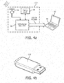
- FIGURE 4a illustrates the wireless probe signal path at the base station host, here shown in the laptop system configuration 50.
- the antenna 54 is coupled to an identical or compatible ultra wideband chip set 96 which performs transception at the host.
- the antenna 54 and ultra wideband chip set are configured as a USB-connectible "dongle" 110 as shown in FIGURE 4b , which plugs into and is powered by a USB port of the host system 50.
- the optional USB link between probe and the host laptop allows charging of the battery in the probe, via the power connection, or wired data transfer when preferred over wireless operation. Further details of the wireless probe and mobile ultrasound system shown in FIGURES 2-4b may be found in US pat. pub. no. 2010/0168576 (Poland et al. )
- the USB radio module 110 also includes a pairing circuit 98. While the pairing circuit 98 in this example is shown located in the radio module 110, it could also be implemented in the ultrasound system.
- the pairing circuit responds to a pairing request from a wireless probe, such as the presence of a wireless probe within the one meter pairing distance, verifies that the probe is within the pairing distance and, if so, commands the ultrasound system 50 to proceed with the pairing protocol.
- Radios such as the UWB chip set commonly produce a signal indicating the strength of received signals known as the received signal strength indicator (RSSI).
- RSSI received signal strength indicator
- An equivalent signal can be produced by envelope-detecting a received probe radio signal, which also indicates the strength (amplitude) of the received signal.
- the RSSI signal from the UWB chip set is coupled to one input of a comparator 32, which compares the RSSI with a threshold voltage V TH . This threshold voltage is preset and is approximately equal to the RSSI produced in response to signals from a wireless probe when the probe is one meter from the radio antenna.
- a wireless probe which is one meter from the mobile system 50 or closer will transmit signals to the system radio which produce an RSSI which equals or exceeds V TH .
- the comparator 32 produces a PAIR signal which is coupled to a low power USB microcontroller 34 along with the data received from the wireless probe by the UWB chip set.
- the received data includes the unique identifier of the wireless probe.
- the USB microcontroller couples the PAIR signal to the USB connector of the radio module 110 so that the mobile ultrasound system 50 receives the PAIR signal in USB format.
- the ultrasound system is thereby notified that a wireless probe has been identified in pairing range and the system responds by reading the probe's unique identifier on the USB data bus 36 and selecting this identifier as the one with which to pair.
- the ultrasound system and probe then exchange pairing protocol data as is known in the art and the communication between the wireless probe and ultrasound system is established.
- This exclusive communication connection remains in place unless the user affirmatively ends it as by pressing a control button; or turns off the wireless probe; or does not use the communication link or is out of radio range for a predetermined extended period of time, whereupon the connection times out and is ended by the system or probe.
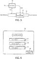
- the mobile ultrasound system can produce a display of the wireless probes within radio range as shown in FIGURE 6 .
- the display screen 56 is showing a list of wireless probes identified to be within radio range, as indicated by their transmitted unique identifier signals.
- the identified probes are preferably listed on the screen in received signal strength order so that the probe nearest to the ultrasound system will be at the top of the list.
- the ultrasound system uses the RSSI to order the list of probes, each of which is displayed on a screen button 42, 44, or 46.
- each probe also has a unique number, which is printed on a label on each probe.
- the user at the ultrasound system is holding a P5-3 wireless probe with the number "#0767" on it.
- the user can thus look at the number on the physical probe and the number of the identified wireless probe at the top of the list and know that a selection of the top probe on the screen list will pair the probe she is holding.
- the mobile ultrasound system also displays a "Pause" user control button 48 in the lower right corner of the screen, which is available while a wireless probe is paired with the system.
- a "Pause" user control button 48 in the lower right corner of the screen, which is available while a wireless probe is paired with the system.
- the user wants to temporarily suspend an exam for another activity, such as taking a phone call or having a discussion with a colleague, the user clicks on the Pause button 48. This action informs the ultrasound system that, even though the wireless probe is currently not being used to scan a patient, the system is to remain paired with the wireless probe and not break the communication.
- the system and probe will thus remain in communication, awaiting continuance of the exam until overridden by another action such as the communication link being affirmatively ended by the user, the probe or system being turned off, the two being out of radio range for an extended time, or depletion of the battery charge of the wireless probe.
Claims (15)
- Système à ultrasons mobile (50) comprenant une radio et un circuit d'appariement (98) destiné à l'appariement d'une sonde à ultrasons sans fil (10) et dudit système à ultrasons mobile (50), le circuit d'appariement (98) étant conçu:- pour localiser une sonde à ultrasons sans fil (10) comportant une radio dans une plage prédéterminée dudit système à ultrasons mobile (50);- pour déterminer que la sonde à ultrasons sans fil (10) présente se trouve dans la plage prédéterminée; et- pour coupler la sonde à ultrasons sans fil (10) et ledit système à ultrasons mobile (50) pour être en communication l'un avec l'autre lorsqu'il est déterminé que la sonde à ultrasons sans fil est présente dans la plage prédéterminée et lorsqu'il est déterminé que ledit système à ultrasons mobile n'est pas en communication avec une autre sonde à ultrasons sans fil.
- Système à ultrasons mobile (50) selon la revendication 1, dans lequel la plage prédéterminée comprend un mètre.
- Système à ultrasons mobile (50) selon la revendication 2, dans lequel la plage prédéterminée est une distance d'un mètre d'une antenne (54) de la radio dudit système à ultrasons mobile.
- Système à ultrasons mobile (50) selon l'une quelconque des revendications 1 à 3, dans lequel la radio dudit système à ultrasons mobile comprend un émetteur-récepteur à ultra-large bande.
- Système à ultrasons mobile (50) selon l'une quelconque des revendications 1 à , dans lequel la radio dudit système à ultrasons mobile comprend un émetteur-récepteur standard Wi-Fi (802.11).
- Système à ultrasons mobile (50) selon l'une quelconque des revendications 1 à 5, dans lequel la radio dudit système à ultrasons mobile est conçue:- pour recevoir un signal radio de la sonde à ultrasons sans fil (10); et- pour produire un signal indiquant la force du signal reçu, etdans lequel le circuit d'appariement (98) est conçu pour déterminer si la sonde à ultrasons sans fil (10) est présente dans la plage prédéterminée en fonction du signal produit.
- Système à ultrasons mobile (50) selon la revendication 6, dans lequel le signal produit comprend un signal indicateur d'intensité de signal reçu.
- Système à ultrasons mobile (50) selon la revendication 6, dans lequel le circuit d'appariement (98) est en outre conçu pour comparer le signal indiquant la force du signal reçu à une tension seuil pour déterminer si la sonde à ultrasons sans fil (10) présente est dans la plage prédéterminée.
- Système à ultrasons mobile (50) selon la revendication 8, dans lequel la tension seuil est configurée pour être égale à un signal indiquant la force du signal reçu lorsque la sonde sans fil (10) est dans la plage prédéterminée dudit système à ultrasons (50).
- Système à ultrasons mobile (50) selon l'une quelconque des revendications 1 à 9, dans lequel ledit système à ultrasons mobile est conçu pour maintenir une liaison de communication établie par l'appariement jusqu'à ce que:- l'utilisateur y met fin par l'affirmative; ou- la sonde à ultrasons sans fil est éteinte; ou- il est déterminé que la sonde à ultrasons sans fil a été hors de portée dudit système à ultrasons mobile pendant une longue période de temps; ou- la communication de nouvelles données sur la liaison a été inactive pendant une période de temps prédéfinie.
- Système à ultrasons mobile (50) selon l'une quelconque des revendications 1 à 10, comprenant en outre: une commande utilisateur conçue pour maintenir la communication entre la sonde à ultrasons sans fil appariée et ledit système à ultrasons mobile pendant la suspension d'un examen par ultrasons.
- Système à ultrasons mobile (50) selon l'une quelconque des revendications 1 à 11, dans lequel le circuit d'appariement (98) est conçu pour localiser une pluralité de sondes à ultrasons sans fil (10), chacune comportant une radio, dans la plage prédéterminée dudit système à ultrasons mobile (50), et pour déterminer que chacune des sondes à ultrasons sans fil présentes se trouve dans la plage prédéterminée;dans lequel la radio dudit système à ultrasons mobile est conçue pour recevoir un signal d'identification unique de chacune des sondes à ultrasons sans fil; dans lequel ledit système à ultrasons mobile comprend en outre un affichage (56) conçu pour afficher les identités des sondes à ultrasons sans fil en correspondance avec les signaux d'identification uniques; etdans lequel le circuit d'appariement (98) est conçu pour apparier une sonde à ultrasons sans fil particulière et ledit système à ultrasons mobile (50) en réponse à une sélection par l'utilisateur de l'identité de la sonde à ultrasons sans fil particulière affichée sur l'écran (56).
- Système à ultrasons mobile (50) selon la revendication 12, dans lequel l'affichage (56) est en outre conçu pour afficher les identités des sondes à ultrasons sans fil dans l'ordre de la force des signaux reçus des sondes.
- Système à ultrasons mobile (50) selon la revendication 12 ou 13, dans lequel l'affichage (56) est en outre conçu pour afficher l'identité d'une sonde à ultrasons sans fil (10) uniquement lorsqu'elle se trouve dans la plage prédéterminée dudit système à ultrasons mobile (50).
- Système à ultrasons mobile (50) selon l'une quelconque des revendications précédentes, comprenant en outre un système hôte, dans lequel la radio dudit système à ultrasons mobile et le circuit d'appariement (98) sont agencés dans une clé électronique connectable par USB conçu pour être branché et alimenté par un port USB dudit système hôte.
Applications Claiming Priority (3)
| Application Number | Priority Date | Filing Date | Title |
|---|---|---|---|
| US201562193210P | 2015-07-16 | 2015-07-16 | |
| PCT/IB2016/053998 WO2017009735A1 (fr) | 2015-07-16 | 2016-07-04 | Appariement de sonde à ultrasons sans fil avec système à ultrasons mobile |
| EP16738226.6A EP3322344B1 (fr) | 2015-07-16 | 2016-07-04 | Appariement de sonde à ultrasons sans fil avec système à ultrasons mobile |
Related Parent Applications (2)
| Application Number | Title | Priority Date | Filing Date |
|---|---|---|---|
| EP16738226.6A Division EP3322344B1 (fr) | 2015-07-16 | 2016-07-04 | Appariement de sonde à ultrasons sans fil avec système à ultrasons mobile |
| EP16738226.6A Division-Into EP3322344B1 (fr) | 2015-07-16 | 2016-07-04 | Appariement de sonde à ultrasons sans fil avec système à ultrasons mobile |
Publications (2)
| Publication Number | Publication Date |
|---|---|
| EP3666194A1 EP3666194A1 (fr) | 2020-06-17 |
| EP3666194B1 true EP3666194B1 (fr) | 2021-09-08 |
Family
ID=56409129
Family Applications (2)
| Application Number | Title | Priority Date | Filing Date |
|---|---|---|---|
| EP20150926.2A Active EP3666194B1 (fr) | 2015-07-16 | 2016-07-04 | Couplage d'une sonde ultrasonore sans fil avec un système ultrasonore mobile |
| EP16738226.6A Active EP3322344B1 (fr) | 2015-07-16 | 2016-07-04 | Appariement de sonde à ultrasons sans fil avec système à ultrasons mobile |
Family Applications After (1)
| Application Number | Title | Priority Date | Filing Date |
|---|---|---|---|
| EP16738226.6A Active EP3322344B1 (fr) | 2015-07-16 | 2016-07-04 | Appariement de sonde à ultrasons sans fil avec système à ultrasons mobile |
Country Status (5)
| Country | Link |
|---|---|
| US (1) | US10835206B2 (fr) |
| EP (2) | EP3666194B1 (fr) |
| JP (2) | JP7346029B2 (fr) |
| CN (1) | CN107847212B (fr) |
| WO (1) | WO2017009735A1 (fr) |
Families Citing this family (53)
| Publication number | Priority date | Publication date | Assignee | Title |
|---|---|---|---|---|
| US11871901B2 (en) | 2012-05-20 | 2024-01-16 | Cilag Gmbh International | Method for situational awareness for surgical network or surgical network connected device capable of adjusting function based on a sensed situation or usage |
| CN117694923A (zh) | 2015-07-21 | 2024-03-15 | 皇家飞利浦有限公司 | 具有处理器软件狗的超声系统 |
| US11026657B2 (en) | 2017-08-25 | 2021-06-08 | Samsung Medison Co., Ltd. | Ultrasound diagnosis apparatus and method of operating the same |
| KR102638273B1 (ko) * | 2017-08-25 | 2024-02-20 | 삼성메디슨 주식회사 | 무선 초음파 프로브와 연결되는 초음파 진단 장치 및 그 동작 방법 |
| US11051787B2 (en) | 2017-08-25 | 2021-07-06 | Samsung Medison Co., Ltd. | Ultrasound diagnosis apparatus connected to wireless ultrasound probes and method of operating the same |
| KR102580426B1 (ko) * | 2017-08-25 | 2023-09-20 | 삼성메디슨 주식회사 | 초음파 진단 장치 및 그 동작 방법 |
| US11911045B2 (en) | 2017-10-30 | 2024-02-27 | Cllag GmbH International | Method for operating a powered articulating multi-clip applier |
| US10980560B2 (en) | 2017-10-30 | 2021-04-20 | Ethicon Llc | Surgical instrument systems comprising feedback mechanisms |
| US11801098B2 (en) | 2017-10-30 | 2023-10-31 | Cilag Gmbh International | Method of hub communication with surgical instrument systems |
| EP3499675B1 (fr) | 2017-12-12 | 2021-03-31 | ABB Power Grids Switzerland AG | Formation d'une grille formant des générateurs de puissance en fonction d'un emplacement dans un micro-réseau |
| US11389164B2 (en) | 2017-12-28 | 2022-07-19 | Cilag Gmbh International | Method of using reinforced flexible circuits with multiple sensors to optimize performance of radio frequency devices |
| US11744604B2 (en) | 2017-12-28 | 2023-09-05 | Cilag Gmbh International | Surgical instrument with a hardware-only control circuit |
| US11969216B2 (en) | 2017-12-28 | 2024-04-30 | Cilag Gmbh International | Surgical network recommendations from real time analysis of procedure variables against a baseline highlighting differences from the optimal solution |
| US11844579B2 (en) | 2017-12-28 | 2023-12-19 | Cilag Gmbh International | Adjustments based on airborne particle properties |
| US11202570B2 (en) | 2017-12-28 | 2021-12-21 | Cilag Gmbh International | Communication hub and storage device for storing parameters and status of a surgical device to be shared with cloud based analytics systems |
| US11672605B2 (en) | 2017-12-28 | 2023-06-13 | Cilag Gmbh International | Sterile field interactive control displays |
| US11109866B2 (en) | 2017-12-28 | 2021-09-07 | Cilag Gmbh International | Method for circular stapler control algorithm adjustment based on situational awareness |
| US11013563B2 (en) | 2017-12-28 | 2021-05-25 | Ethicon Llc | Drive arrangements for robot-assisted surgical platforms |
| US11832899B2 (en) | 2017-12-28 | 2023-12-05 | Cilag Gmbh International | Surgical systems with autonomously adjustable control programs |
| US11132462B2 (en) | 2017-12-28 | 2021-09-28 | Cilag Gmbh International | Data stripping method to interrogate patient records and create anonymized record |
| US11896322B2 (en) | 2017-12-28 | 2024-02-13 | Cilag Gmbh International | Sensing the patient position and contact utilizing the mono-polar return pad electrode to provide situational awareness to the hub |
| US11896443B2 (en) | 2017-12-28 | 2024-02-13 | Cilag Gmbh International | Control of a surgical system through a surgical barrier |
| US11864728B2 (en) | 2017-12-28 | 2024-01-09 | Cilag Gmbh International | Characterization of tissue irregularities through the use of mono-chromatic light refractivity |
| US11166772B2 (en) * | 2017-12-28 | 2021-11-09 | Cilag Gmbh International | Surgical hub coordination of control and communication of operating room devices |
| US11786251B2 (en) | 2017-12-28 | 2023-10-17 | Cilag Gmbh International | Method for adaptive control schemes for surgical network control and interaction |
| US11937769B2 (en) | 2017-12-28 | 2024-03-26 | Cilag Gmbh International | Method of hub communication, processing, storage and display |
| US11969142B2 (en) | 2017-12-28 | 2024-04-30 | Cilag Gmbh International | Method of compressing tissue within a stapling device and simultaneously displaying the location of the tissue within the jaws |
| US11818052B2 (en) | 2017-12-28 | 2023-11-14 | Cilag Gmbh International | Surgical network determination of prioritization of communication, interaction, or processing based on system or device needs |
| US11771487B2 (en) | 2017-12-28 | 2023-10-03 | Cilag Gmbh International | Mechanisms for controlling different electromechanical systems of an electrosurgical instrument |
| US11678881B2 (en) | 2017-12-28 | 2023-06-20 | Cilag Gmbh International | Spatial awareness of surgical hubs in operating rooms |
| US11666331B2 (en) | 2017-12-28 | 2023-06-06 | Cilag Gmbh International | Systems for detecting proximity of surgical end effector to cancerous tissue |
| US11903601B2 (en) | 2017-12-28 | 2024-02-20 | Cilag Gmbh International | Surgical instrument comprising a plurality of drive systems |
| US10758310B2 (en) | 2017-12-28 | 2020-09-01 | Ethicon Llc | Wireless pairing of a surgical device with another device within a sterile surgical field based on the usage and situational awareness of devices |
| US11696760B2 (en) | 2017-12-28 | 2023-07-11 | Cilag Gmbh International | Safety systems for smart powered surgical stapling |
| US11857152B2 (en) | 2017-12-28 | 2024-01-02 | Cilag Gmbh International | Surgical hub spatial awareness to determine devices in operating theater |
| KR102608821B1 (ko) * | 2018-02-08 | 2023-12-04 | 삼성메디슨 주식회사 | 무선 초음파 프로브 및 무선 초음파 프로브와 연결되는 초음파 영상 장치 |
| US11259830B2 (en) | 2018-03-08 | 2022-03-01 | Cilag Gmbh International | Methods for controlling temperature in ultrasonic device |
| US11399858B2 (en) | 2018-03-08 | 2022-08-02 | Cilag Gmbh International | Application of smart blade technology |
| JP7257409B2 (ja) * | 2018-03-09 | 2023-04-13 | ストライカー・コーポレイション | コンソールベースの手術システムの手術器具を遠隔制御するためのシステムおよび方法 |
| US10646205B2 (en) * | 2018-03-27 | 2020-05-12 | Clarius Mobile Health Corp. | Systems and methods of establishing a secondary connection at an ultrasound imaging machine, for providing access to an ultrasound image feed |
| US11090047B2 (en) | 2018-03-28 | 2021-08-17 | Cilag Gmbh International | Surgical instrument comprising an adaptive control system |
| KR102630205B1 (ko) * | 2018-05-31 | 2024-01-26 | 삼성메디슨 주식회사 | 무선 초음파 프로브, 무선 초음파 프로브와 연결되는 초음파 진단 장치 및 그 동작 방법 |
| US11464484B2 (en) * | 2018-09-19 | 2022-10-11 | Clarius Mobile Health Corp. | Systems and methods of establishing a communication session for live review of ultrasound scanning |
| JP6955114B2 (ja) * | 2018-10-11 | 2021-10-27 | 富士フイルム株式会社 | 超音波プローブ |
| US11298130B2 (en) | 2019-02-19 | 2022-04-12 | Cilag Gmbh International | Staple cartridge retainer with frangible authentication key |
| JP7302219B2 (ja) * | 2019-03-25 | 2023-07-04 | オムロンヘルスケア株式会社 | 情報管理システム、及び、計測機器と情報端末の機器登録方法 |
| WO2020205874A1 (fr) * | 2019-04-05 | 2020-10-08 | Butterfly Network, Inc. | Architectures à ultrasons sans fil |
| CN110232848A (zh) * | 2019-05-29 | 2019-09-13 | 长江大学 | 一种超声教学装置及系统 |
| JP7342967B2 (ja) * | 2019-11-06 | 2023-09-12 | 株式会社ソシオネクスト | 超音波プローブ、超音波診断システム、超音波診断プログラム、超音波通信方法 |
| US20210196243A1 (en) * | 2019-12-27 | 2021-07-01 | Canon Medical Systems Corporation | Medical image diagnostics system and ultrasonic probe |
| WO2021174498A1 (fr) * | 2020-03-05 | 2021-09-10 | 深圳迈瑞生物医疗电子股份有限公司 | Procédé de mesure ultrasonore, système, sonde sans fil et support de stockage |
| JP2022032760A (ja) * | 2020-08-14 | 2022-02-25 | キヤノンメディカルシステムズ株式会社 | 超音波診断システム |
| FR3123442A1 (fr) | 2021-05-26 | 2022-12-02 | Echopen Factory | Sonde échographique et procédé de mise en oeuvre |
Family Cites Families (17)
| Publication number | Priority date | Publication date | Assignee | Title |
|---|---|---|---|---|
| US5229933A (en) | 1989-11-28 | 1993-07-20 | Hewlett-Packard Company | 2-d phased array ultrasound imaging system with distributed phasing |
| US5229993A (en) | 1991-02-25 | 1993-07-20 | Old Dominion University | Control of access through local carrier sensing for high data rate networks and control of access of synchronous messages through circulating reservation packets |
| US5997479A (en) | 1998-05-28 | 1999-12-07 | Hewlett-Packard Company | Phased array acoustic systems with intra-group processors |
| US6142946A (en) | 1998-11-20 | 2000-11-07 | Atl Ultrasound, Inc. | Ultrasonic diagnostic imaging system with cordless scanheads |
| US6468216B1 (en) | 2000-08-24 | 2002-10-22 | Kininklijke Philips Electronics N.V. | Ultrasonic diagnostic imaging of the coronary arteries |
| WO2004051882A1 (fr) | 2002-12-04 | 2004-06-17 | Koninklijke Philips Electronics N.V. | Diversite de retard dans un systeme de communication sans fil |
| JP2008018109A (ja) * | 2006-07-14 | 2008-01-31 | Aloka Co Ltd | ワイヤレス超音波診断装置 |
| US20080114241A1 (en) * | 2006-11-10 | 2008-05-15 | Penrith Corporation | Transducer array imaging system |
| US20080114251A1 (en) | 2006-11-10 | 2008-05-15 | Penrith Corporation | Transducer array imaging system |
| US7747223B2 (en) * | 2007-03-29 | 2010-06-29 | Research In Motion Limited | Method, system and mobile device for prioritizing a discovered device list |
| RU2502470C2 (ru) * | 2007-06-01 | 2013-12-27 | Конинклейке Филипс Электроникс, Н.В. | Облегченный беспроводной ультразвуковой датчик |
| EP2422703A4 (fr) * | 2009-04-24 | 2014-04-16 | Panasonic Corp | Dispositif de diagnostic a ultrasons sans fil, sonde a ultrasons sans fil et procede de certification de sonde |
| JP2011072583A (ja) * | 2009-09-30 | 2011-04-14 | Fujifilm Corp | 超音波プローブ、および超音波診断システム |
| JP2013215553A (ja) * | 2012-03-13 | 2013-10-24 | Toshiba Corp | 超音波プローブ及び超音波診断装置 |
| US20140180110A1 (en) * | 2012-12-20 | 2014-06-26 | General Electric Company | System and Method for Wireless Ultrasound Probe Pairing |
| KR102143628B1 (ko) * | 2013-04-30 | 2020-08-11 | 삼성메디슨 주식회사 | 초음파 프로브 및 그 통신 방법 |
| US9763644B2 (en) * | 2015-03-27 | 2017-09-19 | Clarius Mobile Health Corp. | System and method for connecting and controlling wireless ultrasound imaging system from electronic device |
-
2016
- 2016-07-04 WO PCT/IB2016/053998 patent/WO2017009735A1/fr active Application Filing
- 2016-07-04 JP JP2018500884A patent/JP7346029B2/ja active Active
- 2016-07-04 US US15/744,876 patent/US10835206B2/en active Active
- 2016-07-04 EP EP20150926.2A patent/EP3666194B1/fr active Active
- 2016-07-04 CN CN201680041803.9A patent/CN107847212B/zh active Active
- 2016-07-04 EP EP16738226.6A patent/EP3322344B1/fr active Active
-
2021
- 2021-05-07 JP JP2021079048A patent/JP7080376B6/ja active Active
Also Published As
| Publication number | Publication date |
|---|---|
| JP7080376B2 (ja) | 2022-06-03 |
| CN107847212B (zh) | 2021-04-02 |
| CN107847212A (zh) | 2018-03-27 |
| JP7080376B6 (ja) | 2022-06-23 |
| JP2021121333A (ja) | 2021-08-26 |
| EP3666194A1 (fr) | 2020-06-17 |
| EP3322344B1 (fr) | 2020-05-20 |
| JP7346029B2 (ja) | 2023-09-19 |
| EP3322344A1 (fr) | 2018-05-23 |
| JP2018527054A (ja) | 2018-09-20 |
| US10835206B2 (en) | 2020-11-17 |
| WO2017009735A1 (fr) | 2017-01-19 |
| US20180263600A1 (en) | 2018-09-20 |
Similar Documents
| Publication | Publication Date | Title |
|---|---|---|
| EP3666194B1 (fr) | Couplage d'une sonde ultrasonore sans fil avec un système ultrasonore mobile | |
| JP5676252B2 (ja) | 軽量無線超音波プローブ | |
| JP5727785B2 (ja) | 無線超音波プローブケーブル | |
| KR102582542B1 (ko) | 초음파 프로브 및 초음파 프로브 충전 방법 | |
| US20100160784A1 (en) | Wireless Ultrasound Probe With Audible Indicator | |
| JP6465835B2 (ja) | 医療診断イメージング超音波プローブバッテリーパック通信機器 | |
| EP3508133A1 (fr) | Système à ultrasons doté d'une clé électronique (dongle) de processeur | |
| WO2008146206A2 (fr) | Suivi d'équipements pour sonde ultrasonore sans fil | |
| KR101365439B1 (ko) | 초음파 진단을 위한 프로브의 무선 통신 방법 및 이를 위한 장치 | |
| EP3175794B1 (fr) | Appareil de diagnostic à ultrasons, ensemble de support et procédé permettant de commander l'appareil de diagnostic à ultrasons | |
| KR20150102590A (ko) | 무선 프로브 및 그에 따른 무선 프로브의 전원 제어 방법 | |
| JP2015531642A (ja) | モバイル3dワイヤレス超音波画像取得装置及び超音波イメージングシステム | |
| KR20160087240A (ko) | 무선 초음파 프로브 및 이를 포함하는 초음파 장치 | |
| US11730449B2 (en) | Ultrasonic diagnostic system | |
| CN107249468B (zh) | 超声波诊断系统 | |
| US11564664B2 (en) | Ultrasound diagnostic apparatus and control method thereof | |
| CN107427287B (zh) | 超声波诊断系统以及超声波诊断系统的动作方法 | |
| JP7413014B2 (ja) | 医用画像診断システム | |
| CN211213224U (zh) | 一种超声探头及超声诊断设备 | |
| KR102264756B1 (ko) | 무선 프로브 및 그에 따른 무선 프로브의 전원 제어 방법 |
Legal Events
| Date | Code | Title | Description |
|---|---|---|---|
| PUAI | Public reference made under article 153(3) epc to a published international application that has entered the european phase |
Free format text: ORIGINAL CODE: 0009012 |
|
| STAA | Information on the status of an ep patent application or granted ep patent |
Free format text: STATUS: THE APPLICATION HAS BEEN PUBLISHED |
|
| AC | Divisional application: reference to earlier application |
Ref document number: 3322344 Country of ref document: EP Kind code of ref document: P |
|
| AK | Designated contracting states |
Kind code of ref document: A1 Designated state(s): AL AT BE BG CH CY CZ DE DK EE ES FI FR GB GR HR HU IE IS IT LI LT LU LV MC MK MT NL NO PL PT RO RS SE SI SK SM TR |
|
| STAA | Information on the status of an ep patent application or granted ep patent |
Free format text: STATUS: REQUEST FOR EXAMINATION WAS MADE |
|
| 17P | Request for examination filed |
Effective date: 20201217 |
|
| RBV | Designated contracting states (corrected) |
Designated state(s): AL AT BE BG CH CY CZ DE DK EE ES FI FR GB GR HR HU IE IS IT LI LT LU LV MC MK MT NL NO PL PT RO RS SE SI SK SM TR |
|
| GRAP | Despatch of communication of intention to grant a patent |
Free format text: ORIGINAL CODE: EPIDOSNIGR1 |
|
| STAA | Information on the status of an ep patent application or granted ep patent |
Free format text: STATUS: GRANT OF PATENT IS INTENDED |
|
| INTG | Intention to grant announced |
Effective date: 20210304 |
|
| GRAS | Grant fee paid |
Free format text: ORIGINAL CODE: EPIDOSNIGR3 |
|
| GRAA | (expected) grant |
Free format text: ORIGINAL CODE: 0009210 |
|
| STAA | Information on the status of an ep patent application or granted ep patent |
Free format text: STATUS: THE PATENT HAS BEEN GRANTED |
|
| AC | Divisional application: reference to earlier application |
Ref document number: 3322344 Country of ref document: EP Kind code of ref document: P |
|
| AK | Designated contracting states |
Kind code of ref document: B1 Designated state(s): AL AT BE BG CH CY CZ DE DK EE ES FI FR GB GR HR HU IE IS IT LI LT LU LV MC MK MT NL NO PL PT RO RS SE SI SK SM TR |
|
| REG | Reference to a national code |
Ref country code: GB Ref legal event code: FG4D |
|
| REG | Reference to a national code |
Ref country code: AT Ref legal event code: REF Ref document number: 1427840 Country of ref document: AT Kind code of ref document: T Effective date: 20210915 Ref country code: CH Ref legal event code: EP |
|
| REG | Reference to a national code |
Ref country code: IE Ref legal event code: FG4D |
|
| REG | Reference to a national code |
Ref country code: DE Ref legal event code: R096 Ref document number: 602016063634 Country of ref document: DE |
|
| REG | Reference to a national code |
Ref country code: DE Ref legal event code: R084 Ref document number: 602016063634 Country of ref document: DE |
|
| REG | Reference to a national code |
Ref country code: GB Ref legal event code: 746 Effective date: 20211112 |
|
| REG | Reference to a national code |
Ref country code: LT Ref legal event code: MG9D |
|
| REG | Reference to a national code |
Ref country code: NL Ref legal event code: MP Effective date: 20210908 |
|
| PG25 | Lapsed in a contracting state [announced via postgrant information from national office to epo] |
Ref country code: ES Free format text: LAPSE BECAUSE OF FAILURE TO SUBMIT A TRANSLATION OF THE DESCRIPTION OR TO PAY THE FEE WITHIN THE PRESCRIBED TIME-LIMIT Effective date: 20210908 Ref country code: RS Free format text: LAPSE BECAUSE OF FAILURE TO SUBMIT A TRANSLATION OF THE DESCRIPTION OR TO PAY THE FEE WITHIN THE PRESCRIBED TIME-LIMIT Effective date: 20210908 Ref country code: SE Free format text: LAPSE BECAUSE OF FAILURE TO SUBMIT A TRANSLATION OF THE DESCRIPTION OR TO PAY THE FEE WITHIN THE PRESCRIBED TIME-LIMIT Effective date: 20210908 Ref country code: LT Free format text: LAPSE BECAUSE OF FAILURE TO SUBMIT A TRANSLATION OF THE DESCRIPTION OR TO PAY THE FEE WITHIN THE PRESCRIBED TIME-LIMIT Effective date: 20210908 Ref country code: BG Free format text: LAPSE BECAUSE OF FAILURE TO SUBMIT A TRANSLATION OF THE DESCRIPTION OR TO PAY THE FEE WITHIN THE PRESCRIBED TIME-LIMIT Effective date: 20211208 Ref country code: FI Free format text: LAPSE BECAUSE OF FAILURE TO SUBMIT A TRANSLATION OF THE DESCRIPTION OR TO PAY THE FEE WITHIN THE PRESCRIBED TIME-LIMIT Effective date: 20210908 Ref country code: HR Free format text: LAPSE BECAUSE OF FAILURE TO SUBMIT A TRANSLATION OF THE DESCRIPTION OR TO PAY THE FEE WITHIN THE PRESCRIBED TIME-LIMIT Effective date: 20210908 Ref country code: NO Free format text: LAPSE BECAUSE OF FAILURE TO SUBMIT A TRANSLATION OF THE DESCRIPTION OR TO PAY THE FEE WITHIN THE PRESCRIBED TIME-LIMIT Effective date: 20211208 |
|
| REG | Reference to a national code |
Ref country code: AT Ref legal event code: MK05 Ref document number: 1427840 Country of ref document: AT Kind code of ref document: T Effective date: 20210908 |
|
| PG25 | Lapsed in a contracting state [announced via postgrant information from national office to epo] |
Ref country code: LV Free format text: LAPSE BECAUSE OF FAILURE TO SUBMIT A TRANSLATION OF THE DESCRIPTION OR TO PAY THE FEE WITHIN THE PRESCRIBED TIME-LIMIT Effective date: 20210908 Ref country code: GR Free format text: LAPSE BECAUSE OF FAILURE TO SUBMIT A TRANSLATION OF THE DESCRIPTION OR TO PAY THE FEE WITHIN THE PRESCRIBED TIME-LIMIT Effective date: 20211209 |
|
| PG25 | Lapsed in a contracting state [announced via postgrant information from national office to epo] |
Ref country code: AT Free format text: LAPSE BECAUSE OF FAILURE TO SUBMIT A TRANSLATION OF THE DESCRIPTION OR TO PAY THE FEE WITHIN THE PRESCRIBED TIME-LIMIT Effective date: 20210908 |
|
| PG25 | Lapsed in a contracting state [announced via postgrant information from national office to epo] |
Ref country code: IS Free format text: LAPSE BECAUSE OF FAILURE TO SUBMIT A TRANSLATION OF THE DESCRIPTION OR TO PAY THE FEE WITHIN THE PRESCRIBED TIME-LIMIT Effective date: 20220108 Ref country code: SM Free format text: LAPSE BECAUSE OF FAILURE TO SUBMIT A TRANSLATION OF THE DESCRIPTION OR TO PAY THE FEE WITHIN THE PRESCRIBED TIME-LIMIT Effective date: 20210908 Ref country code: SK Free format text: LAPSE BECAUSE OF FAILURE TO SUBMIT A TRANSLATION OF THE DESCRIPTION OR TO PAY THE FEE WITHIN THE PRESCRIBED TIME-LIMIT Effective date: 20210908 Ref country code: RO Free format text: LAPSE BECAUSE OF FAILURE TO SUBMIT A TRANSLATION OF THE DESCRIPTION OR TO PAY THE FEE WITHIN THE PRESCRIBED TIME-LIMIT Effective date: 20210908 Ref country code: PT Free format text: LAPSE BECAUSE OF FAILURE TO SUBMIT A TRANSLATION OF THE DESCRIPTION OR TO PAY THE FEE WITHIN THE PRESCRIBED TIME-LIMIT Effective date: 20220110 Ref country code: PL Free format text: LAPSE BECAUSE OF FAILURE TO SUBMIT A TRANSLATION OF THE DESCRIPTION OR TO PAY THE FEE WITHIN THE PRESCRIBED TIME-LIMIT Effective date: 20210908 Ref country code: NL Free format text: LAPSE BECAUSE OF FAILURE TO SUBMIT A TRANSLATION OF THE DESCRIPTION OR TO PAY THE FEE WITHIN THE PRESCRIBED TIME-LIMIT Effective date: 20210908 Ref country code: EE Free format text: LAPSE BECAUSE OF FAILURE TO SUBMIT A TRANSLATION OF THE DESCRIPTION OR TO PAY THE FEE WITHIN THE PRESCRIBED TIME-LIMIT Effective date: 20210908 Ref country code: CZ Free format text: LAPSE BECAUSE OF FAILURE TO SUBMIT A TRANSLATION OF THE DESCRIPTION OR TO PAY THE FEE WITHIN THE PRESCRIBED TIME-LIMIT Effective date: 20210908 Ref country code: AL Free format text: LAPSE BECAUSE OF FAILURE TO SUBMIT A TRANSLATION OF THE DESCRIPTION OR TO PAY THE FEE WITHIN THE PRESCRIBED TIME-LIMIT Effective date: 20210908 |
|
| REG | Reference to a national code |
Ref country code: DE Ref legal event code: R097 Ref document number: 602016063634 Country of ref document: DE |
|
| PLBE | No opposition filed within time limit |
Free format text: ORIGINAL CODE: 0009261 |
|
| STAA | Information on the status of an ep patent application or granted ep patent |
Free format text: STATUS: NO OPPOSITION FILED WITHIN TIME LIMIT |
|
| PG25 | Lapsed in a contracting state [announced via postgrant information from national office to epo] |
Ref country code: DK Free format text: LAPSE BECAUSE OF FAILURE TO SUBMIT A TRANSLATION OF THE DESCRIPTION OR TO PAY THE FEE WITHIN THE PRESCRIBED TIME-LIMIT Effective date: 20210908 |
|
| 26N | No opposition filed |
Effective date: 20220609 |
|
| PG25 | Lapsed in a contracting state [announced via postgrant information from national office to epo] |
Ref country code: SI Free format text: LAPSE BECAUSE OF FAILURE TO SUBMIT A TRANSLATION OF THE DESCRIPTION OR TO PAY THE FEE WITHIN THE PRESCRIBED TIME-LIMIT Effective date: 20210908 |
|
| PG25 | Lapsed in a contracting state [announced via postgrant information from national office to epo] |
Ref country code: IT Free format text: LAPSE BECAUSE OF FAILURE TO SUBMIT A TRANSLATION OF THE DESCRIPTION OR TO PAY THE FEE WITHIN THE PRESCRIBED TIME-LIMIT Effective date: 20210908 |
|
| PG25 | Lapsed in a contracting state [announced via postgrant information from national office to epo] |
Ref country code: MC Free format text: LAPSE BECAUSE OF FAILURE TO SUBMIT A TRANSLATION OF THE DESCRIPTION OR TO PAY THE FEE WITHIN THE PRESCRIBED TIME-LIMIT Effective date: 20210908 |
|
| REG | Reference to a national code |
Ref country code: CH Ref legal event code: PL |
|
| REG | Reference to a national code |
Ref country code: BE Ref legal event code: MM Effective date: 20220731 |
|
| PG25 | Lapsed in a contracting state [announced via postgrant information from national office to epo] |
Ref country code: LU Free format text: LAPSE BECAUSE OF NON-PAYMENT OF DUE FEES Effective date: 20220704 Ref country code: LI Free format text: LAPSE BECAUSE OF NON-PAYMENT OF DUE FEES Effective date: 20220731 Ref country code: CH Free format text: LAPSE BECAUSE OF NON-PAYMENT OF DUE FEES Effective date: 20220731 |
|
| PG25 | Lapsed in a contracting state [announced via postgrant information from national office to epo] |
Ref country code: BE Free format text: LAPSE BECAUSE OF NON-PAYMENT OF DUE FEES Effective date: 20220731 |
|
| PG25 | Lapsed in a contracting state [announced via postgrant information from national office to epo] |
Ref country code: IE Free format text: LAPSE BECAUSE OF NON-PAYMENT OF DUE FEES Effective date: 20220704 |
|
| PGFP | Annual fee paid to national office [announced via postgrant information from national office to epo] |
Ref country code: GB Payment date: 20230725 Year of fee payment: 8 |
|
| PGFP | Annual fee paid to national office [announced via postgrant information from national office to epo] |
Ref country code: FR Payment date: 20230725 Year of fee payment: 8 Ref country code: DE Payment date: 20230726 Year of fee payment: 8 |
|
| PG25 | Lapsed in a contracting state [announced via postgrant information from national office to epo] |
Ref country code: MK Free format text: LAPSE BECAUSE OF FAILURE TO SUBMIT A TRANSLATION OF THE DESCRIPTION OR TO PAY THE FEE WITHIN THE PRESCRIBED TIME-LIMIT Effective date: 20210908 Ref country code: CY Free format text: LAPSE BECAUSE OF FAILURE TO SUBMIT A TRANSLATION OF THE DESCRIPTION OR TO PAY THE FEE WITHIN THE PRESCRIBED TIME-LIMIT Effective date: 20210908 |