EP3666047B1 - Kühlsystem mit parallelen kühlkanälen - Google Patents
Kühlsystem mit parallelen kühlkanälen Download PDFInfo
- Publication number
- EP3666047B1 EP3666047B1 EP18800554.0A EP18800554A EP3666047B1 EP 3666047 B1 EP3666047 B1 EP 3666047B1 EP 18800554 A EP18800554 A EP 18800554A EP 3666047 B1 EP3666047 B1 EP 3666047B1
- Authority
- EP
- European Patent Office
- Prior art keywords
- cooling
- air
- power converter
- channels
- cooling system
- Prior art date
- Legal status (The legal status is an assumption and is not a legal conclusion. Google has not performed a legal analysis and makes no representation as to the accuracy of the status listed.)
- Active
Links
Images
Classifications
-
- H—ELECTRICITY
- H05—ELECTRIC TECHNIQUES NOT OTHERWISE PROVIDED FOR
- H05K—PRINTED CIRCUITS; CASINGS OR CONSTRUCTIONAL DETAILS OF ELECTRIC APPARATUS; MANUFACTURE OF ASSEMBLAGES OF ELECTRICAL COMPONENTS
- H05K7/00—Constructional details common to different types of electric apparatus
- H05K7/20—Modifications to facilitate cooling, ventilating, or heating
- H05K7/2089—Modifications to facilitate cooling, ventilating, or heating for power electronics, e.g. for inverters for controlling motor
-
- H—ELECTRICITY
- H05—ELECTRIC TECHNIQUES NOT OTHERWISE PROVIDED FOR
- H05K—PRINTED CIRCUITS; CASINGS OR CONSTRUCTIONAL DETAILS OF ELECTRIC APPARATUS; MANUFACTURE OF ASSEMBLAGES OF ELECTRICAL COMPONENTS
- H05K7/00—Constructional details common to different types of electric apparatus
- H05K7/20—Modifications to facilitate cooling, ventilating, or heating
- H05K7/20009—Modifications to facilitate cooling, ventilating, or heating using a gaseous coolant in electronic enclosures
- H05K7/20136—Forced ventilation, e.g. by fans
-
- H—ELECTRICITY
- H05—ELECTRIC TECHNIQUES NOT OTHERWISE PROVIDED FOR
- H05K—PRINTED CIRCUITS; CASINGS OR CONSTRUCTIONAL DETAILS OF ELECTRIC APPARATUS; MANUFACTURE OF ASSEMBLAGES OF ELECTRICAL COMPONENTS
- H05K7/00—Constructional details common to different types of electric apparatus
- H05K7/20—Modifications to facilitate cooling, ventilating, or heating
- H05K7/2089—Modifications to facilitate cooling, ventilating, or heating for power electronics, e.g. for inverters for controlling motor
- H05K7/20909—Forced ventilation, e.g. on heat dissipaters coupled to components
- H05K7/20918—Forced ventilation, e.g. on heat dissipaters coupled to components the components being isolated from air flow, e.g. hollow heat sinks, wind tunnels or funnels
-
- H—ELECTRICITY
- H05—ELECTRIC TECHNIQUES NOT OTHERWISE PROVIDED FOR
- H05K—PRINTED CIRCUITS; CASINGS OR CONSTRUCTIONAL DETAILS OF ELECTRIC APPARATUS; MANUFACTURE OF ASSEMBLAGES OF ELECTRICAL COMPONENTS
- H05K7/00—Constructional details common to different types of electric apparatus
- H05K7/20—Modifications to facilitate cooling, ventilating, or heating
- H05K7/20009—Modifications to facilitate cooling, ventilating, or heating using a gaseous coolant in electronic enclosures
- H05K7/20136—Forced ventilation, e.g. by fans
- H05K7/20145—Means for directing air flow, e.g. ducts, deflectors, plenum or guides
-
- H—ELECTRICITY
- H05—ELECTRIC TECHNIQUES NOT OTHERWISE PROVIDED FOR
- H05K—PRINTED CIRCUITS; CASINGS OR CONSTRUCTIONAL DETAILS OF ELECTRIC APPARATUS; MANUFACTURE OF ASSEMBLAGES OF ELECTRICAL COMPONENTS
- H05K7/00—Constructional details common to different types of electric apparatus
- H05K7/20—Modifications to facilitate cooling, ventilating, or heating
- H05K7/20009—Modifications to facilitate cooling, ventilating, or heating using a gaseous coolant in electronic enclosures
- H05K7/20209—Thermal management, e.g. fan control
Definitions
- the invention relates to a cooling system for a power converter.
- the invention further relates to a power converter with such a cooling system.
- the invention further relates to a method for regulating and/or controlling such a cooling system or such a power converter.
- Power converters for converting electrical energy generate power loss, which results in heat loss. This heat must be dissipated from the corresponding components in order to protect them from damage.
- power loss occurs particularly in the power section.
- Different electrical components are used there, which heat up during operation due to electrical losses and must be cooled in order to ensure the required service life of the components.
- These are essentially the semiconductors (e.g. IGBTs) and the intermediate circuit capacitors. Since the service life of intermediate circuit capacitors is strongly influenced by the ambient temperature, this should not exceed approx. 70°C in order to be able to use standard components. These standard components are available on the market at low prices and have an impact on the low manufacturing costs of the power converter.
- the intermediate circuit capacitors are arranged in an air stream for cooling either in front of the semiconductors or using an air bypass. This ensures that they are supplied with cool, i.e. not preheated, cooling air.
- a frequency converter for driving a motor comprises a circuit board with at least one first heat-generating circuit board mounted thereon Element, a heat sink connected to the at least one first heat-generating element, a fan facing the heat sink, and a bracket for positioning the at least one heat-generating element relative to the heat sink and the circuit board.
- the frequency converter further includes a separating member for separating the at least a portion of the main body of the at least one second heat generating element from the circuit board to prevent the cooling air from being directed to the at least one second heat generator.
- the frequency converter comprises an air flow guide element which is arranged between the fan and the heat sink in order to guide the cooling air moved by the fan to the heat sink or to the at least one second heat-generating element and a flow guide gate which guides the air flow from the fan to the heat sink and emits more airflow to flow through the area corresponding to the at least one first heat-generating element.
- the cooling structure for an electronic device having an inlet for promoting a flow in a first flow direction to a first component and an outlet for directing the flow.
- the cooling structure can comprise a second flow channel, which starts from an opening oriented transversely to or away from the first flow direction and receives part of the flow from the inlet and conveys the part of the flow to an electronic component , which is located in the second flow channel.
- the invention is based on the object of improving a cooling system for a power converter.
- This task is solved by a cooling system for a power converter with the features of claim 1. Furthermore, the task is solved by a power converter with the features of claim 4. This task is further accomplished through a procedure for regulation and/or control solved with the features of claim 5.
- the invention is based on the finding that a good supply of sufficiently cool cooling medium, for example air or water, can be achieved by a parallel arrangement of two cooling channels for cooling intermediate circuit capacitors and semiconductors in the device.
- the semiconductors are also referred to as power semiconductors due to the high switchable currents.
- direct flow and hermetically separated cooling channels are provided for these two different components.
- both the intermediate circuit capacitors and the semiconductors are cooled with a non-preheated cooling medium.
- the intermediate circuit capacitors this has the advantage that permissible maximum temperatures are reliably maintained.
- the significantly higher power loss of the semiconductors can be reliably dissipated.
- Mutual influence can be easily avoided by the parallel arrangement.
- the two cooling channels can also be used to achieve a relatively simple, low-inductance device design with very simple busbars for power supply for the DC and AC rails. Due to this arrangement, the volume of the entire device can be made very compact.
- the cooling channels are designed as air channels.
- the use of air has proven to be particularly advantageous. This can be taken from the environment and fed to the components to be cooled using the cooling channels. It is easily possible to divide the cooling air into two parallel cooling channels. In contrast to cooling with the cooling medium water, there is no need for a recooler, which releases the heat in the water into the environment. With that leaves A particularly simple and at the same time very effective cooling system can be realized.
- the cooling system has an air distributor, the air distributor being advantageously designed to divide the air flow between the first cooling channel and the second cooling channel in a ratio of 90:10. Since the intermediate circuit capacitors require the lowest possible temperature of the cooling medium, but the power loss in the semiconductors is significantly greater than in the intermediate circuit capacitors, it has proven to be advantageous to distribute the total air flow via an air distributor in a ratio of 90:10 (air volume of semiconductor in relation to intermediate circuit capacitor). to divide. Studies have shown that divisions in the range of 80:20 to 95:5 produce good and, above all, uniform cooling results.
- a measured temperature value is used to divide the cooling air between the first and second cooling channels.
- the cooling system has a temperature sensor for this purpose.
- This temperature measurement value can be used directly or after processing, for example after calculations in a temperature model, to regulate or control the air distribution between the two cooling channels.
- the temperature sensor can, for example, measure a temperature of a component to be cooled located in the cooling air duct.
- the temperature of the cooling air, in particular the exhaust air i.e. after it has absorbed heat from the component to be cooled, can also be measured and used to regulate or control the distribution.
- the advantage of air division depending on a temperature reading is that the components to be cooled can be optimally cooled in the two air ducts depending on the operating conditions.
- the division can be aligned in such a way that the loss of service life due to the heating of the components to be cooled is evened out.
- it is possible to regulate or control both the amount of air and the distribution of the air so that the temperature of the components to be cooled adopts a reference value and remains at this value during operation. By avoiding temperature fluctuations, the service life of the components to be cooled is increased.
- the cooling system has exactly one fan, which is arranged to generate cooling air flows in the first and second cooling channels.
- all of the cooling air required for both air ducts can be brought to the intermediate circuit capacitors and the semiconductors by just one fan.
- the fan generates cooling air flows in both the first and second cooling channels. The required cooling air is blown into the two cooling channels by the fan.
- the air distributor can have openings of different sizes for dividing the air between the two cooling channels, so that the corresponding distribution ratio results.
- these openings can be equipped with movable flaps with which the distribution ratio can be adjusted.
- the advantage of adaptation is that it is possible to react to different distributions of power loss, for example depending on the operating point of the power converter, and the cooling can be designed optimally for both components.
- the division can also be controlled or regulated, for example, depending on the temperature of the intermediate circuit capacitors and/or the semiconductors.
- Another possibility for dividing the air between the two cooling channels is to provide a means for reducing the pressure for at least one of the cooling channels. This also makes it easy to influence the distribution of the amount of cooling air between the two cooling channels.
- the first and second cooling channels are arranged spatially parallel in the area of the parallel arrangement.
- the outer skin of the first cooling channel extends at least in sections parallel to the outer skin of the second cooling channel.
- the intermediate circuit capacitors and the semiconductors can also be arranged parallel to one another in the power converter. With regard to the electrical behavior, this makes it possible to achieve a particularly simple and low-inductance device structure with very simple busbars for carrying current for the DC and AC rails. Due to this arrangement, the construction volume of the power converter can be made very compact and therefore cost-effective.
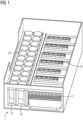
- the FIG 1 shows a cooling system 1 for the use of the cooling medium air.
- This cooling system 1 has a first cooling channel 11 and a second cooling channel 12. These extend spatially parallel through the illustrated section of the power converter 2.
- the separate cooling channels for cooling the semiconductors 21 and the cooling of the intermediate circuit capacitors 22 can be clearly seen.
- the first cooling channel 11 serves to cool the semiconductors 21, which are mounted on a heat sink are.
- the cooling fins of the heat sink protrude into the first cooling channel 11.
- the semiconductors 21 thus release the heat generated by power loss via the heat sink to the cooling medium air. Overheating of the semiconductors 21 can thus be reliably prevented.
- the intermediate circuit capacitors 22 are arranged in the second cooling channel 12. These are located in the second cooling channel 12 and are surrounded by the cooling medium air. The intermediate circuit capacitors 22 release the heat that arises due to losses in the capacitors. Since the loss conduction of the semiconductors 21 is larger than that of the intermediate circuit capacitors 22, the effective cross-sectional area of the first cooling channel 11 is also larger than the effective cross-sectional area of the second cooling channel 12. The effective cross-sectional area is the cross-sectional area of the cooling channel 11, 12 minus the components such as intermediate circuit capacitors protruding therein 22 or cooling fins.
- An air distributor 4, not shown here, at the entrance to the two cooling channels 11, 12 is used to control the air distribution between the two cooling channels 11, 12. This can be used, for example, depending on the operating point and/or those measured on the semiconductors 21 and/or the intermediate circuit capacitors 22 Temperatures, the distribution of the cooling air between the two cooling channels 11, 12 are controlled or regulated.
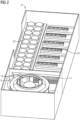
- the FIG 2 shows a power converter 2 with a cooling system 1. To avoid repetition, please refer to the description FIG 1 as well as reference numbers introduced there.
- the power converter 2 has a fan 3. Via the air distributor 4, not shown here, a cooling air flow is generated by the fan 3 in both the first cooling channel 11 and the second cooling channel 12.
- the invention relates to a cooling system for a power converter.
- the cooling system In order to improve the cooling system, it is proposed to equip the cooling system with a first cooling channel and a second cooling channel, the first and the second cooling channel being arranged in parallel at least in sections, the first cooling channel being designed for cooling semiconductors of the power converter in the area of the parallel arrangement, wherein in the area of the parallel arrangement the second cooling channel for cooling intermediate circuit capacitors of the power converter.
- the invention further relates to a power converter with such a cooling system.
Landscapes
- Engineering & Computer Science (AREA)
- Microelectronics & Electronic Packaging (AREA)
- Physics & Mathematics (AREA)
- Thermal Sciences (AREA)
- Rectifiers (AREA)
- Power Conversion In General (AREA)
- Inverter Devices (AREA)
- Cooling Or The Like Of Semiconductors Or Solid State Devices (AREA)
Description
- Die Erfindung betrifft ein Kühlsystem für einen Stromrichter. Ferner betrifft die Erfindung ein Stromrichter mit einem derartigen Kühlsystem. Weiter betrifft die Erfindung ein Verfahren zur Regelung und/oder Steuerung eines derartigen Kühlsystems oder derartigen Stromrichters.
- Stromrichter zur Umwandlung von elektrischer Energie erzeugen Verlustleistung, die sich in Verlustwärme zeigen. Diese Wärme muss aus den entsprechenden Bauteilen abgeführt werden, um diese vor Beschädigungen zu schützen. In einem Stromrichter entsteht Verlustleistung im Besonderen im Leistungsteil. Dort werden unterschiedliche elektrische Komponenten eingesetzt, die sich im Betrieb aufgrund elektrischer Verluste erwärmen und gekühlt werden müssen um eine erforderliche Lebensdauer der Komponenten gewährleisten zu können. Dies sind im Wesentlichen die Halbleiter (z.B. IGBT's) und die Zwischenkreiskondensatoren. Da die Lebensdauer von Zwischenkreiskondensatoren sehr stark durch die Umgebungstemperatur beeinflusst wird, sollte diese ca. 70°C nicht übersteigen um Standardkomponenten verwenden zu können. Diese Standardkomponenten sind preisgünstig am Markt verfügbar und wirken sich auf niedrige Herstellkosten des Stromrichters aus.
- Aufgrund der geringen zulässigen Umgebungstemperatur für die Zwischenkreiskondensatoren gibt es eine Vorgabe hinsichtlich der Anordnung in einem luftgekühlten Leistungsteil. Dabei werden die Zwischenkreiskondensatoren in einem Luftstrom zur Kühlung entweder vor den Halbleitern oder mittels Luft-Bypass angeordnet. So wird sichergestellt, dass sie mit kühler, d.h. nicht vorerwärmter, Kühlluft versorgt werden.
- Aus der
US 2010/202109 A1 ist ein Frequenzumrichter zum Antrieb eines Motors bekannt- Dieser umfasst eine Leiterplatte mit mindestens einem darauf montierten ersten wärmeerzeugenden Element, einen Kühlkörper, der mit dem mindestens einen ersten wärmeerzeugenden Element verbunden ist, einen Lüfter, der dem Kühlkörper zugewandt ist und eine Halterung zum Positionieren des mindestens einen wärmeerzeugenden Elements relativ zu dem Kühlkörper und der Leiterplatte. Der Frequenzumrichter umfasst ferner ein Trennelement zum Trennen des mindestens einen Abschnitts des Hauptkörpers des mindestens einen zweiten wärmeerzeugenden Elements von der Leiterplatte, um zu verhindern, dass die Kühlluft zu dem mindestens einen zweiten Wärmeerzeuger geleitet wird. Ferner umfasst der Frequenzumrichter ein Luftstromführungselement, das zwischen dem Lüfter und dem Kühlkörper angeordnet ist, um die vom Lüfter bewegte Kühlluft zu dem Kühlkörper bzw. zu dem mindestens einen zweiten wärmeerzeugenden Element zu leiten und ein Strömungsleittor, das den Luftstrom vom Lüfter zum Kühlkörper leitet und mehr Luftstrom abgibt, um durch den Bereich zu strömen, der dem mindestens einen ersten wärmeerzeugenden Element entspricht. - Aus der
US 2011/198064 A1 ist eine Kühlstruktur für ein elektronisches Gerät mit einem Einlass zum Fördern einer Strömung in einer ersten Strömungsrichtung zu einer ersten Komponente und einem Auslass zum Weiterleiten der Strömung bekannt. Um zu verhindern, dass Schmutzpartikel zu elektronischen Bauteilen gelangen, kann die Kühlstruktur einen zweiten Strömungskanal umfassen, der von einer quer zur ersten Strömungsrichtung oder davon weg orientierten Öffnung ausgeht und einen Teil der Strömung vom Einlass aufnimmt und den Teil der Strömung zu einem elektronischen Bauteil fördert, das sich im zweiten Strömungskanal befindet. - Der Erfindung liegt die Aufgabe zugrunde ein Kühlsystem für einen Stromrichter zu verbessern.
- Diese Aufgabe wird durch ein Kühlsystem für einen Stromrichter mit den Merkmalen des Anspruchs 1 gelöst. Ferner wird die Aufgabe durch einen Stromrichter mit den Merkmalen des Anspruchs 4 gelöst. Weiter wird diese Aufgabe durch ein Verfahren zur Regelung und/oder Steuerung mit den Merkmalen des Anspruchs 5 gelöst.
- Vorteilhafte Ausgestaltungen der Erfindung sind in den abhängigen Ansprüchen angegeben.
- Der Erfindung liegt die Erkenntnis zugrunde, dass eine gute Versorgung mit hinreichend kühlem Kühlmedium, beispielsweise mit Luft oder Wasser, durch eine parallele Anordnung von zwei Kühlkanälen zur Kühlung von Zwischenkreiskondensatoren und Halbleitern im Gerät erzielt werden kann. Die Halbleiter werden aufgrund der hohen schaltbaren Ströme auch als Leistungshalbleiter bezeichnet. Dazu werden für diese beiden unterschiedlichen Komponenten direkt angeströmte und hermetisch getrennte Kühlkanäle vorgesehen. Durch die beiden Kühlkanale werden sowohl Zwischenkreiskondensatoren als auch die Halbleiter mit einem nicht vorerwärmten Kühlmedium gekühlt. Für die Zwischenkreiskondensatoren hat dies den Vorteil, dass zulässige Maximaltemperaturen zuverlässig eingehalten werden. Gleichzeitig kann die deutlich höhere Verlustleistung der Halbleiter zuverlässig abgeführt werden. Eine gegenseitige Beeinflussung kann dabei auf einfache Weise durch die parallele Anordnung vermieden werden. Neben den thermischen Vorteilen kann mit den beiden Kühlkanälen auch ein relativ einfacher, niederinduktiver Geräteaufbau mit sehr einfachen Stromschienen zur Stromführung für die DC- und AC-Schienen erreicht werden. Aufgrund dieser Anordnung lässt sich das Bauvolumen des Gesamtgerätes sehr kompakt gestalten.
- Dabei sind die Kühlkanale als Luftkanäle ausgebildet. Die Verwendung von Luft hat sich als besonders vorteilhaft erwiesen. Diese kann der Umgebung entnommen werden und mittels der Kühlkanäle den zu kühlenden Komponenten zugeführt werden. Eine Aufteilung der Kühlluft auf zwei parallele Kühlkanäle ist dabei problemlos möglich. Im Gegensatz zur Kühlung mit dem Kühlmedium Wasser kann auf einen Rückkühler, der die Wärme im Wasser an die Umgebung abgibt, verzichtet werden. Damit lässt sich ein besonders einfach aufgebautes und gleichzeitig sehr wirkungsvolles Kühlsystem realisieren.
- Dabei weist das Kühlsystem einen Luftverteiler auf, wobei der Luftverteiler derart in vorteilhafter Weise derart ausgebildet ist, den Luftstrom zwischen dem ersten Kühlkanal und dem zweiten Kühlkanal im Verhältnis 90:10 aufzuteilen. Da die Zwischenkreiskondensatoren zwar eine möglichst geringe Temperatur des Kühlmediums benötigen aber die Verlustleistung in den Halbleitern deutlich größer ist als in den Zwischenkreiskondensatoren hat es sich als vorteilhaft erwiesen, den Gesamtluftstrom über einen Luftverteiler im Verhältnis von 90:10 (Luftmenge Halbleiter im Verhältnis zu Zwischenkreiskondensator) aufzuteilen. Untersuchungen haben ergeben, dass Aufteilungen im Bereich 80:20 bis 95:5 gute und vor allem gleichmäßige Kühlungsergebnisse mit sich bringen.
- Dazu wird für die Aufteilung der Kühlluft auf den ersten und den zweiten Kühlkanal ein Messwert einer Temperatur herangezogen. Dazu weist das Kühlsystem einen Temperatursensor aus. Dieser Temperaturmesswert kann direkt oder nach Verarbeitung, beispielsweise nach Berechnungen in einem Temperaturmodell, für die Regelung bzw. Steuerung der Luftaufteilung zwischen den beiden Kühlkanälen verwendet werden. Der Temperatursensor kann dabei beispielsweise eine Temperatur einer im Kühlluftkanal befindlichen, zu kühlenden Komponente messen. Alternativ oder ergänzend kann auch die Temperatur der Kühlluft, insbesondere der Abluft, d.h. nachdem sie Wärme der zu kühlenden Komponente aufgenommen hat, gemessen werden und für die Regelung bzw. Steuerung der Aufteilung verwendet werden.
- Der Vorteil der Luftaufteilung in Abhängigkeit von einem Temperaturmesswert liegt darin, dass die zu kühlenden Komponenten in den beiden Luftkanälen je nach Betriebsbedingungen optimal gekühlt werden können. Dabei kann beispielsweise die Aufteilung so ausgerichtet werden, dass der Lebensdauerverlust durch die Erwärmung der zu kühlenden Komponenten vergleichmäßigt wird. Alternativ oder ergänzend ist es möglich, sowohl die Luftmenge als auch die Aufteilung der Luft so zu regeln oder zu steuern, dass sich die Temperatur der zu kühlenden Komponenten einen Referenzwert annimmt und im Betrieb auf diesen Wert bleibt. Durch die Vermeidung von Temperaturschwankungen wird die Lebensdauer der zu kühlenden Komponenten erhöht.
- Bei einer vorteilhaften Ausgestaltung der Erfindung weist das Kühlsystem genau einen Lüfter auf, der derart angeordnet ist, Kühlluftströme im ersten und im zweiten Kühlkanal zu erzeugen. Die gesamte benötigte Kühlluft für beide Luftkanäle kann bei dieser Ausgestaltung durch nur einen Lüfter an die Zwischenkreiskondensatoren und die Halbleiter herangeführt werden. Der Lüfter erzeugt dabei Kühlluftströme sowohl im ersten wie auch im zweiten Kühlkanal. Dabei wird die benötigte Kühlluft vom Lüfter in die beiden Kühlkanäle geblasen.
- Der Luftverteiler kann dabei für die Aufteilung der Luft auf die beiden Kühlkanäle Öffnungen unterschiedlicher Größe aufweisen, so dass sich das entsprechende Aufteilungsverhältnis ergibt. Alternativ oder ergänzend können diese Öffnungen mit beweglichen Klappen ausgestattet sein, mit denen das Verhältnis der Aufteilung anpassbar ist. Der Vorteil der Anpassung liegt daran, dass auf unterschiedliche Verlustleistungsaufteilungen, beispielsweise abhängig vom Betriebspunkt des Stromrichters reagiert werden kann und die Kühlung für beide Komponenten optimal gestaltet werden kann. Die Aufteilung kann beispielsweise auch in Abhängigkeit der Temperatur der Zwischenkreiskondensatoren und/oder der Halbleiter gesteuert oder geregelt werden.
- Eine weitere Möglichkeit, die Luftaufteilung auf die zwei Kühlkanäle vorzunehmen ist, ein Mittel zur Reduzierung des Drucks für mindestens einen der Kühlkanäle vorzusehen. Damit lässt sich ebenfalls auf einfache Weise die Aufteilung der Kühlluftmenge auf die beiden Kühlkanäle beeinflussen.
- Bei einer weiteren vorteilhaften Ausgestaltung der Erfindung sind der erste und der zweite Kühlkanal im Bereich der parallelen Anordnung räumlich parallel angeordnet. Bei der räumlich parallelen Anordnung erstreckt sich die Außenhaut des ersten Kühlkanals zumindest abschnittsweise parallel zur Außenhaut des zweiten Kühlkanals. Durch die räumlich parallele Anordnung können auch die Zwischenkreiskondensatoren und die Halbleiter parallel zueinander im Stromrichter angeordnet werden. Damit lässt sich auch im Hinblick auf das elektrische Verhalten ein besonders einfacher und niederinduktiver Geräteaufbau mit sehr einfachen Stromschienen zur Stromführung für die DC- und AC-Schienen erzielen. Aufgrund dieser Anordnung lässt sich das Bauvolumen des Stromrichters sehr kompakt und damit kostengünstig gestalten.
- Im Folgenden wird die Erfindung anhand der in den Figuren dargestellten Ausführungsbeispiele näher beschrieben und erläutert. Es zeigen:
- FIG 1
- zwei Kühlkanäle eines Stromrichters und
- FIG 2
- einen Stromrichter
- Die
FIG 1 zeigt ein Kühlsystem 1 für die Verwendung des Kühlmediums Luft. Dieses Kühlsystem 1 weist einen ersten Kühlkanal 11 und einen zweiten Kühlkanal 12 auf. Diese erstrecken sich räumlich parallel durch den dargestellten Ausschnitt des Stromrichters 2. Deutlich zu erkennen sind die getrennten Kühlkanäle für die Kühlung der Halbleiter 21 und die Kühlung der Zwischenkreiskondensatoren 22. Dabei dient der erste Kühlkanal 11 zur Kühlung der Halbleiter 21, die auf einen Kühlkörper montiert sind. Die Kühlrippen des Kühlkörpers ragen in den ersten Kühlkanal 11. Damit geben die Halbleiter 21 die durch Verlustleistung erzeugte Wärme über den Kühlkörper an das Kühlmedium Luft ab. Eine Überhitzung der Halbleiter 21 kann somit zuverlässig verhindert werden. - Im zweiten Kühlkanal 12 sind die Zwischenkreiskondensatoren 22 angeordnet. Diese befinden sich im zweiten Kühlkanal 12 und werden von dem Kühlmedium Luft umspült. Dabei geben die Zwischenkreiskondensatoren 22 die Wärme ab, die aufgrund von Verlusten in den Kondensatoren entstehen. Da die Verlustleitung der Halbleiter 21 größer ist als die der Zwischenkreiskondensatoren 22 ist auch die wirksame Querschnittfläche des ersten Kühlkanals 11 größer als die wirksame Querschnittfläche des zweiten Kühlkanals 12. Die wirksame Querschnittsfläche ist die Querschnittsfläche des Kühlkanals 11, 12 abzüglich der darin hineinragenden Komponenten wie Zwischenkreiskondensatoren 22 oder Kühlrippen.
- Zur Steuerung der Luftaufteilung zwischen den beiden Kühlkanälen 11, 12 dient ein hier nicht dargestellter Luftverteiler 4 am Eingang der beiden Kühlkanäle 11, 12. Mit diesem kann, beispielsweise abhängig vom Arbeitspunkt und/oder den an den Halbleitern 21 und/oder den Zwischenkreiskondensatoren 22 gemessenen Temperaturen, die Aufteilung der Kühlluft auf die beiden Kühlkanäle 11, 12 gesteuert oder geregelt werden.
- Die
FIG 2 zeigt einen Stromrichter 2 mit einem Kühlsystem 1. Zur Vermeidung von Wiederholungen wird auf die Beschreibung zurFIG 1 sowie auf die dort eingeführten Bezugszeichen verwiesen. Zur Erzeugung eines Kühlluftstromes weist der Stromrichter 2 einen Lüfter 3 auf. Über den hier nicht dargestellten Luftverteiler 4 wird durch den Lüfter 3 ein Kühlluftstrom sowohl im ersten Kühlkanal 11 wie auch zweiten Kühlkanal 12 erzeugt. - Zusammenfassend betrifft die Erfindung ein Kühlsystem für einen Stromrichter. Zur Verbesserung des Kühlsystems wird vorgeschlagen, das Kühlsystem mit einem ersten Kühlkanal und einem zweiten Kühlkanal auszustatten, Wobei der erste und der zweite Kühlkanal zumindest abschnittsweise parallel angeordnet sind, wobei im Bereich der parallelen Anordnung der erste Kühlkanal zur Kühlung von Halbleitern des Stromrichters ausgebildet ist, wobei im Bereich der parallelen Anordnung der zweite Kühlkanal zur Kühlung von Zwischenkreiskondensatoren des Stromrichters ausgebildet ist. Ferner betrifft die Erfindung einen Stromrichter mit einem derartigen Kühlsystem.
Claims (6)
- Kühlsystem (1) für einen Stromrichter (2), aufweisend- einen ersten Kühlkanal (11)- einen zweiten Kühlkanal (12)wobei der erste und der zweite Kühlkanal (11,12) zumindest abschnittsweise parallel angeordnet sind, wobei im Bereich der parallelen Anordnung der erste Kühlkanal (11) zur Kühlung von Halbleitern (21) des Stromrichters (2) ausgebildet ist, wobei im Bereich der parallelen Anordnung der zweite Kühlkanal (12) zur Kühlung von Zwischenkreiskondensatoren (22) des Stromrichters (2) ausgebildet ist, wobei die Kühlkanale (11,12) als Luftkanäle ausgebildet sind, wobei das Kühlsystem (1) einen Luftverteiler aufweist,dadurch gekennzeichnet, dass das Kühlsystem mindestens einen Temperatursensor aufweist, wobei der Luftverteiler derart ausgebildet ist, den Luftstrom zwischen dem ersten Kühlkanal (11) und dem zweiten Kühlkanal (12) in Abhängigkeit von mindestens einem Messwert des mindestens einen Temperatursensors im Verhältnis in einem Bereich von 80:20 bis 95:5 aufzuteilen.
- Kühlsystem (1) nach Anspruch 1, wobei das Kühlsystem (1) genau einen Lüfter (2) aufweist, der derart angeordnet ist, Kühlluftströme im ersten und im zweiten Kühlkanal (11,12) zu erzeugen.
- Kühlsystem (1) nach einem der Ansprüche 1 oder 2, wobei der erste und der zweite Kühlkanal (11,12) im Bereich der parallelen Anordnung räumlich parallel angeordnet sind.
- Stromrichter (2) mit einem Kühlsystem (1) nach einem der Ansprüche 1 bis 3.
- Verfahren zur Regelung und/oder Steuerung eines Kühlsystems (1) nach einem der Ansprüche 1 bis 3 oder eines Stromrichters (2) nach Anspruch 4, wobei die Aufteilung des Luftstroms in Abhängigkeit von einem Messwert des mindestens einen Temperatursensors erfolgt.
- Verfahren nach Anspruch 5, wobei die Aufteilung des Luftstroms in Abhängigkeit von der Temperatur der in den jeweiligen Kühlkanälen befindlichen zu kühlenden Komponenten und/oder der Temperatur der Kühlluft in den jeweiligen Kühlkanälen erfolgt.
Applications Claiming Priority (2)
| Application Number | Priority Date | Filing Date | Title |
|---|---|---|---|
| EP17203775.6A EP3490353A1 (de) | 2017-11-27 | 2017-11-27 | Kühlsystem mit parallelen kühlkanälen |
| PCT/EP2018/080019 WO2019101494A1 (de) | 2017-11-27 | 2018-11-02 | Kühlsystem mit parallelen kühlkanälen |
Publications (3)
| Publication Number | Publication Date |
|---|---|
| EP3666047A1 EP3666047A1 (de) | 2020-06-17 |
| EP3666047B1 true EP3666047B1 (de) | 2024-03-13 |
| EP3666047C0 EP3666047C0 (de) | 2024-03-13 |
Family
ID=60473398
Family Applications (2)
| Application Number | Title | Priority Date | Filing Date |
|---|---|---|---|
| EP17203775.6A Withdrawn EP3490353A1 (de) | 2017-11-27 | 2017-11-27 | Kühlsystem mit parallelen kühlkanälen |
| EP18800554.0A Active EP3666047B1 (de) | 2017-11-27 | 2018-11-02 | Kühlsystem mit parallelen kühlkanälen |
Family Applications Before (1)
| Application Number | Title | Priority Date | Filing Date |
|---|---|---|---|
| EP17203775.6A Withdrawn EP3490353A1 (de) | 2017-11-27 | 2017-11-27 | Kühlsystem mit parallelen kühlkanälen |
Country Status (5)
| Country | Link |
|---|---|
| US (1) | US11178798B2 (de) |
| EP (2) | EP3490353A1 (de) |
| CN (2) | CN117042403A (de) |
| RU (1) | RU2745399C1 (de) |
| WO (1) | WO2019101494A1 (de) |
Families Citing this family (3)
| Publication number | Priority date | Publication date | Assignee | Title |
|---|---|---|---|---|
| DE102020213972B4 (de) | 2020-11-06 | 2022-10-13 | Robert Bosch Gesellschaft mit beschränkter Haftung | Leistungsmodul mit einer geteilten Wärmesenke |
| EP4102682A1 (de) * | 2021-06-09 | 2022-12-14 | Siemens Gamesa Renewable Energy A/S | Generator, windturbine und verfahren zur kühlung eines direktantriebsgenerators einer windturbine |
| CN119482089B (zh) * | 2024-12-31 | 2025-04-18 | 浙江晨旭物联科技有限公司 | 一种智能型户外综合配电箱 |
Family Cites Families (26)
| Publication number | Priority date | Publication date | Assignee | Title |
|---|---|---|---|---|
| EP0356991B1 (de) * | 1988-08-31 | 1995-01-11 | Hitachi, Ltd. | Wechselrichtervorrichtung |
| CN101202528B (zh) * | 2006-12-11 | 2012-10-10 | 丹佛斯传动有限公司 | 电子装置及电动机变频器 |
| CN101202529A (zh) * | 2006-12-11 | 2008-06-18 | 丹佛斯传动有限公司 | 电子装置及电动机变频器 |
| TWI356673B (en) * | 2008-07-30 | 2012-01-11 | Compal Electronics Inc | Fan assembly |
| FI20085945L (fi) * | 2008-10-08 | 2010-04-09 | Abb Oy | Elektroniikkalaitteen jäähdytysrakenne ja menetelmä |
| DE102008061488A1 (de) | 2008-12-10 | 2010-06-17 | Siemens Aktiengesellschaft | Stromrichtermodul mit gekühlter Verschienung |
| FI20095436A7 (fi) * | 2009-04-21 | 2010-10-22 | Abb Oy | Sähkökäyttö |
| JP4662315B2 (ja) * | 2009-05-20 | 2011-03-30 | 株式会社安川電機 | ファンユニットとこれを備えた電子機器装置 |
| CN104085293B (zh) | 2009-08-03 | 2016-11-23 | 本田技研工业株式会社 | 车辆用高压电气部件的冷却构造 |
| JP5418847B2 (ja) * | 2009-08-04 | 2014-02-19 | 株式会社安川電機 | 電力変換装置 |
| US8325479B2 (en) * | 2010-07-16 | 2012-12-04 | Rockwell Automation Technologies, Inc. | Motor drive cooling duct system and method |
| DE102010044439A1 (de) * | 2010-09-06 | 2012-03-08 | Chloride S.P.A. | Kühlsystem für leistungselektronische Umrichter |
| RU2465152C2 (ru) | 2010-09-15 | 2012-10-27 | Федеральное государственное унитарное предприятие "Научное производственное объединение автоматики" имени академика Н.А. Семихатова | Система воздушного охлаждения блоков пускотормозных резисторов |
| EP2557676B1 (de) * | 2011-08-09 | 2014-02-26 | Siemens Aktiengesellschaft | Umrichteranordnung mit einem Luftkühlsystem |
| WO2013023321A1 (en) | 2011-08-15 | 2013-02-21 | Nuovo Pignone S.P.A. | Mixing manifold and method |
| EP2562922A1 (de) * | 2011-08-26 | 2013-02-27 | Siemens Aktiengesellschaft | Modular aufgebaute Stromrichteranordnung |
| CN103140116B (zh) | 2011-11-30 | 2015-09-09 | 华为技术有限公司 | 机架系统的温控方法和机架系统的送风系统 |
| KR101294077B1 (ko) | 2011-12-09 | 2013-08-07 | 현대자동차주식회사 | 전력 변환 장치용 냉각 시스템 |
| US20130242504A1 (en) * | 2012-03-19 | 2013-09-19 | Andrew C. Cartes | Cooling an electronic assembly using position variable flow restrictors |
| CN104519715A (zh) * | 2013-09-30 | 2015-04-15 | 施耐德东芝换流器欧洲公司 | 变频器设备的散热结构和控制方法及设备 |
| EP2879476B1 (de) * | 2013-11-29 | 2016-06-29 | ABB Technology Oy | Elektrische Vorrichtung |
| US20160174413A1 (en) * | 2014-12-16 | 2016-06-16 | Intel Corporation | Cooling for components of electronic devices |
| CN105873412B (zh) * | 2015-01-20 | 2018-08-14 | 上海宽带技术及应用工程研究中心 | 冷气流通道分配结构及机柜 |
| JP2017093092A (ja) | 2015-11-06 | 2017-05-25 | 富士電機株式会社 | 電源装置 |
| CN106253635A (zh) | 2016-08-17 | 2016-12-21 | 常州博瑞电力自动化设备有限公司 | 一种直流输电换流阀双配水冷却系统 |
| CN106604618B (zh) * | 2017-01-05 | 2024-01-09 | 中国科学院广州能源研究所 | 一种用于数据中心的液冷、风冷复合冷却装置 |
-
2017
- 2017-11-27 EP EP17203775.6A patent/EP3490353A1/de not_active Withdrawn
-
2018
- 2018-11-02 US US16/767,015 patent/US11178798B2/en active Active
- 2018-11-02 CN CN202311044517.6A patent/CN117042403A/zh active Pending
- 2018-11-02 EP EP18800554.0A patent/EP3666047B1/de active Active
- 2018-11-02 CN CN201880076369.7A patent/CN111418274A/zh active Pending
- 2018-11-02 RU RU2020117193A patent/RU2745399C1/ru active
- 2018-11-02 WO PCT/EP2018/080019 patent/WO2019101494A1/de not_active Ceased
Also Published As
| Publication number | Publication date |
|---|---|
| CN117042403A (zh) | 2023-11-10 |
| WO2019101494A1 (de) | 2019-05-31 |
| EP3666047A1 (de) | 2020-06-17 |
| CN111418274A (zh) | 2020-07-14 |
| US11178798B2 (en) | 2021-11-16 |
| EP3490353A1 (de) | 2019-05-29 |
| US20210037682A1 (en) | 2021-02-04 |
| EP3666047C0 (de) | 2024-03-13 |
| RU2745399C1 (ru) | 2021-03-24 |
Similar Documents
| Publication | Publication Date | Title |
|---|---|---|
| EP2557676B1 (de) | Umrichteranordnung mit einem Luftkühlsystem | |
| EP3401956B1 (de) | Leistungshalbleitermodul für ein kraftfahrzeug und kraftfahrzeug | |
| DE102019128721B4 (de) | Leistungselektronikvorrichtung für eine fremderregte Synchronmaschine und Kraftfahrzeug | |
| EP3666047B1 (de) | Kühlsystem mit parallelen kühlkanälen | |
| DE102014214209B4 (de) | Kühlvorrichtung zur zielgerichteten Kühlung von elektronischen und/oder elektrischen Bauelementen, Umrichter mit einer derartigen Kühlvorrichtung sowie Elektro- oder Hybridfahrzeug mit einem derartigen Umrichter | |
| DE102021129145A1 (de) | Verfahren zum aktiven Entladen eines elektrischen Energiespeichers, Steuereinrichtung, elektrische Schaltungseinrichtung und Kraftfahrzeug | |
| DE102022114113A1 (de) | Pulswechselrichter mit einer Kühleinrichtung sowie Kraftfahrzeug mit einem Pulswechselrichter | |
| WO2019154685A1 (de) | Elektrische antriebseinheit für ein kraftfahrzeug | |
| DE112015004772T5 (de) | Leistungsmodul, elektrische Leistungsumsetzungsvorrichtung und Antriebsgerät für ein Fahrzeug | |
| EP3490351B1 (de) | Niederspannungsschaltgerät mit einer definierten kühlanordnung | |
| DE102019209829A1 (de) | Vorrichtung umfassend einen Kühlkörper und Kraftfahrzeug | |
| DE102015202487A1 (de) | Energieumwandlungsvorrichtung und mit derselben ausgerüstetes schienenfahrzeug | |
| DE10224265A1 (de) | Elektrische Heizvorrichtung zum Beheizen von Luft, insbesondere für ein Kraftfahrzeug | |
| DE102021111773A1 (de) | Verfahren zum aktiven Entladen eines elektrischen Energiespeichers, Steuereinrichtung, elektrische Schaltungseinrichtung und Kraftfahrzeug | |
| EP3850743B1 (de) | Gleichstromschalter | |
| WO2008040596A2 (de) | Kühlkörper zur kühlung eines elektrischen bauelementes | |
| DE102009054374A1 (de) | Belastungswiderstandsanordnung | |
| EP3811455A1 (de) | Vorrichtung zur energieverteilung und/oder energieumwandlung in einem hybrid- oder elektrofahrzeug | |
| DE102017103413A1 (de) | Kühlsystem mit aktiv gekühlter Stromversorgungselektronik | |
| EP1949520A1 (de) | Vorrichtung zum umrichten eines elektrischen stromes und verfahren zur reduzierung der lastwechselbeanspruchung von leistungshalbleitereinheiten im bereich der hochspannungsenergieverteilung und -übertragung | |
| DE102023110479A1 (de) | Kraftfahrzeug umfassend einen direktgekühlten Wechselrichter und einen Kühlkreislauf | |
| DE102023123809B3 (de) | Verfahren und Pulswechselrichter zur Kühlung von Komponenten | |
| DE19951217A1 (de) | Einrichtung mit mindestens einer Brennstoffzelle | |
| DE102018206053B4 (de) | Schaltungsanordnung und Kraftfahrzeug | |
| EP3618255A1 (de) | Schalteinrichtung zum schalten von hochspannungen zur kabelprüfung durch beaufschlagung eines kabelprüflings mit der hochspannung und entlagung des kabelprüflings |
Legal Events
| Date | Code | Title | Description |
|---|---|---|---|
| STAA | Information on the status of an ep patent application or granted ep patent |
Free format text: STATUS: UNKNOWN |
|
| STAA | Information on the status of an ep patent application or granted ep patent |
Free format text: STATUS: THE INTERNATIONAL PUBLICATION HAS BEEN MADE |
|
| PUAI | Public reference made under article 153(3) epc to a published international application that has entered the european phase |
Free format text: ORIGINAL CODE: 0009012 |
|
| STAA | Information on the status of an ep patent application or granted ep patent |
Free format text: STATUS: REQUEST FOR EXAMINATION WAS MADE |
|
| 17P | Request for examination filed |
Effective date: 20200312 |
|
| AK | Designated contracting states |
Kind code of ref document: A1 Designated state(s): AL AT BE BG CH CY CZ DE DK EE ES FI FR GB GR HR HU IE IS IT LI LT LU LV MC MK MT NL NO PL PT RO RS SE SI SK SM TR |
|
| AX | Request for extension of the european patent |
Extension state: BA ME |
|
| DAV | Request for validation of the european patent (deleted) | ||
| DAX | Request for extension of the european patent (deleted) | ||
| STAA | Information on the status of an ep patent application or granted ep patent |
Free format text: STATUS: EXAMINATION IS IN PROGRESS |
|
| 17Q | First examination report despatched |
Effective date: 20210311 |
|
| GRAP | Despatch of communication of intention to grant a patent |
Free format text: ORIGINAL CODE: EPIDOSNIGR1 |
|
| STAA | Information on the status of an ep patent application or granted ep patent |
Free format text: STATUS: GRANT OF PATENT IS INTENDED |
|
| INTG | Intention to grant announced |
Effective date: 20231127 |
|
| GRAS | Grant fee paid |
Free format text: ORIGINAL CODE: EPIDOSNIGR3 |
|
| GRAA | (expected) grant |
Free format text: ORIGINAL CODE: 0009210 |
|
| STAA | Information on the status of an ep patent application or granted ep patent |
Free format text: STATUS: THE PATENT HAS BEEN GRANTED |
|
| AK | Designated contracting states |
Kind code of ref document: B1 Designated state(s): AL AT BE BG CH CY CZ DE DK EE ES FI FR GB GR HR HU IE IS IT LI LT LU LV MC MK MT NL NO PL PT RO RS SE SI SK SM TR |
|
| REG | Reference to a national code |
Ref country code: GB Ref legal event code: FG4D Free format text: NOT ENGLISH |
|
| REG | Reference to a national code |
Ref country code: CH Ref legal event code: EP |
|
| REG | Reference to a national code |
Ref country code: DE Ref legal event code: R096 Ref document number: 502018014265 Country of ref document: DE |
|
| REG | Reference to a national code |
Ref country code: IE Ref legal event code: FG4D Free format text: LANGUAGE OF EP DOCUMENT: GERMAN |
|
| U01 | Request for unitary effect filed |
Effective date: 20240318 |
|
| U07 | Unitary effect registered |
Designated state(s): AT BE BG DE DK EE FI FR IT LT LU LV MT NL PT SE SI Effective date: 20240325 |
|
| PG25 | Lapsed in a contracting state [announced via postgrant information from national office to epo] |
Ref country code: GR Free format text: LAPSE BECAUSE OF FAILURE TO SUBMIT A TRANSLATION OF THE DESCRIPTION OR TO PAY THE FEE WITHIN THE PRESCRIBED TIME-LIMIT Effective date: 20240614 |
|
| PG25 | Lapsed in a contracting state [announced via postgrant information from national office to epo] |
Ref country code: RS Free format text: LAPSE BECAUSE OF FAILURE TO SUBMIT A TRANSLATION OF THE DESCRIPTION OR TO PAY THE FEE WITHIN THE PRESCRIBED TIME-LIMIT Effective date: 20240613 Ref country code: HR Free format text: LAPSE BECAUSE OF FAILURE TO SUBMIT A TRANSLATION OF THE DESCRIPTION OR TO PAY THE FEE WITHIN THE PRESCRIBED TIME-LIMIT Effective date: 20240313 |
|
| PG25 | Lapsed in a contracting state [announced via postgrant information from national office to epo] |
Ref country code: ES Free format text: LAPSE BECAUSE OF FAILURE TO SUBMIT A TRANSLATION OF THE DESCRIPTION OR TO PAY THE FEE WITHIN THE PRESCRIBED TIME-LIMIT Effective date: 20240313 |
|
| PG25 | Lapsed in a contracting state [announced via postgrant information from national office to epo] |
Ref country code: RS Free format text: LAPSE BECAUSE OF FAILURE TO SUBMIT A TRANSLATION OF THE DESCRIPTION OR TO PAY THE FEE WITHIN THE PRESCRIBED TIME-LIMIT Effective date: 20240613 Ref country code: NO Free format text: LAPSE BECAUSE OF FAILURE TO SUBMIT A TRANSLATION OF THE DESCRIPTION OR TO PAY THE FEE WITHIN THE PRESCRIBED TIME-LIMIT Effective date: 20240613 Ref country code: HR Free format text: LAPSE BECAUSE OF FAILURE TO SUBMIT A TRANSLATION OF THE DESCRIPTION OR TO PAY THE FEE WITHIN THE PRESCRIBED TIME-LIMIT Effective date: 20240313 Ref country code: GR Free format text: LAPSE BECAUSE OF FAILURE TO SUBMIT A TRANSLATION OF THE DESCRIPTION OR TO PAY THE FEE WITHIN THE PRESCRIBED TIME-LIMIT Effective date: 20240614 Ref country code: ES Free format text: LAPSE BECAUSE OF FAILURE TO SUBMIT A TRANSLATION OF THE DESCRIPTION OR TO PAY THE FEE WITHIN THE PRESCRIBED TIME-LIMIT Effective date: 20240313 |
|
| PG25 | Lapsed in a contracting state [announced via postgrant information from national office to epo] |
Ref country code: IS Free format text: LAPSE BECAUSE OF FAILURE TO SUBMIT A TRANSLATION OF THE DESCRIPTION OR TO PAY THE FEE WITHIN THE PRESCRIBED TIME-LIMIT Effective date: 20240713 |
|
| PG25 | Lapsed in a contracting state [announced via postgrant information from national office to epo] |
Ref country code: SM Free format text: LAPSE BECAUSE OF FAILURE TO SUBMIT A TRANSLATION OF THE DESCRIPTION OR TO PAY THE FEE WITHIN THE PRESCRIBED TIME-LIMIT Effective date: 20240313 |
|
| PG25 | Lapsed in a contracting state [announced via postgrant information from national office to epo] |
Ref country code: CZ Free format text: LAPSE BECAUSE OF FAILURE TO SUBMIT A TRANSLATION OF THE DESCRIPTION OR TO PAY THE FEE WITHIN THE PRESCRIBED TIME-LIMIT Effective date: 20240313 |
|
| PG25 | Lapsed in a contracting state [announced via postgrant information from national office to epo] |
Ref country code: PL Free format text: LAPSE BECAUSE OF FAILURE TO SUBMIT A TRANSLATION OF THE DESCRIPTION OR TO PAY THE FEE WITHIN THE PRESCRIBED TIME-LIMIT Effective date: 20240313 |
|
| PG25 | Lapsed in a contracting state [announced via postgrant information from national office to epo] |
Ref country code: SK Free format text: LAPSE BECAUSE OF FAILURE TO SUBMIT A TRANSLATION OF THE DESCRIPTION OR TO PAY THE FEE WITHIN THE PRESCRIBED TIME-LIMIT Effective date: 20240313 |
|
| PG25 | Lapsed in a contracting state [announced via postgrant information from national office to epo] |
Ref country code: SM Free format text: LAPSE BECAUSE OF FAILURE TO SUBMIT A TRANSLATION OF THE DESCRIPTION OR TO PAY THE FEE WITHIN THE PRESCRIBED TIME-LIMIT Effective date: 20240313 Ref country code: SK Free format text: LAPSE BECAUSE OF FAILURE TO SUBMIT A TRANSLATION OF THE DESCRIPTION OR TO PAY THE FEE WITHIN THE PRESCRIBED TIME-LIMIT Effective date: 20240313 Ref country code: RO Free format text: LAPSE BECAUSE OF FAILURE TO SUBMIT A TRANSLATION OF THE DESCRIPTION OR TO PAY THE FEE WITHIN THE PRESCRIBED TIME-LIMIT Effective date: 20240313 Ref country code: PL Free format text: LAPSE BECAUSE OF FAILURE TO SUBMIT A TRANSLATION OF THE DESCRIPTION OR TO PAY THE FEE WITHIN THE PRESCRIBED TIME-LIMIT Effective date: 20240313 Ref country code: IS Free format text: LAPSE BECAUSE OF FAILURE TO SUBMIT A TRANSLATION OF THE DESCRIPTION OR TO PAY THE FEE WITHIN THE PRESCRIBED TIME-LIMIT Effective date: 20240713 Ref country code: CZ Free format text: LAPSE BECAUSE OF FAILURE TO SUBMIT A TRANSLATION OF THE DESCRIPTION OR TO PAY THE FEE WITHIN THE PRESCRIBED TIME-LIMIT Effective date: 20240313 |
|
| REG | Reference to a national code |
Ref country code: DE Ref legal event code: R097 Ref document number: 502018014265 Country of ref document: DE |
|
| U20 | Renewal fee for the european patent with unitary effect paid |
Year of fee payment: 7 Effective date: 20241118 |
|
| PLBE | No opposition filed within time limit |
Free format text: ORIGINAL CODE: 0009261 |
|
| STAA | Information on the status of an ep patent application or granted ep patent |
Free format text: STATUS: NO OPPOSITION FILED WITHIN TIME LIMIT |
|
| 26N | No opposition filed |
Effective date: 20241216 |
|
| REG | Reference to a national code |
Ref country code: CH Ref legal event code: PL |
|
| PG25 | Lapsed in a contracting state [announced via postgrant information from national office to epo] |
Ref country code: MC Free format text: LAPSE BECAUSE OF FAILURE TO SUBMIT A TRANSLATION OF THE DESCRIPTION OR TO PAY THE FEE WITHIN THE PRESCRIBED TIME-LIMIT Effective date: 20240313 |
|
| REG | Reference to a national code |
Ref country code: CH Ref legal event code: PL |
|
| GBPC | Gb: european patent ceased through non-payment of renewal fee |
Effective date: 20241102 |
|
| PG25 | Lapsed in a contracting state [announced via postgrant information from national office to epo] |
Ref country code: CH Free format text: LAPSE BECAUSE OF NON-PAYMENT OF DUE FEES Effective date: 20241130 |
|
| PG25 | Lapsed in a contracting state [announced via postgrant information from national office to epo] |
Ref country code: GB Free format text: LAPSE BECAUSE OF NON-PAYMENT OF DUE FEES Effective date: 20241102 |
|
| PG25 | Lapsed in a contracting state [announced via postgrant information from national office to epo] |
Ref country code: IE Free format text: LAPSE BECAUSE OF NON-PAYMENT OF DUE FEES Effective date: 20241102 |
|
| U20 | Renewal fee for the european patent with unitary effect paid |
Year of fee payment: 8 Effective date: 20251120 |
|
| PG25 | Lapsed in a contracting state [announced via postgrant information from national office to epo] |
Ref country code: HU Free format text: LAPSE BECAUSE OF FAILURE TO SUBMIT A TRANSLATION OF THE DESCRIPTION OR TO PAY THE FEE WITHIN THE PRESCRIBED TIME-LIMIT; INVALID AB INITIO Effective date: 20181102 |