EP3665780B1 - Vereinheitlichtes muster zur punktion und verkürzung von polaren codes - Google Patents
Vereinheitlichtes muster zur punktion und verkürzung von polaren codes Download PDFInfo
- Publication number
- EP3665780B1 EP3665780B1 EP17922027.2A EP17922027A EP3665780B1 EP 3665780 B1 EP3665780 B1 EP 3665780B1 EP 17922027 A EP17922027 A EP 17922027A EP 3665780 B1 EP3665780 B1 EP 3665780B1
- Authority
- EP
- European Patent Office
- Prior art keywords
- bits
- blocks
- encoded bits
- circular buffer
- encoded
- Prior art date
- Legal status (The legal status is an assumption and is not a legal conclusion. Google has not performed a legal analysis and makes no representation as to the accuracy of the status listed.)
- Active
Links
Images


Classifications
-
- H—ELECTRICITY
- H03—ELECTRONIC CIRCUITRY
- H03M—CODING; DECODING; CODE CONVERSION IN GENERAL
- H03M13/00—Coding, decoding or code conversion, for error detection or error correction; Coding theory basic assumptions; Coding bounds; Error probability evaluation methods; Channel models; Simulation or testing of codes
- H03M13/03—Error detection or forward error correction by redundancy in data representation, i.e. code words containing more digits than the source words
- H03M13/05—Error detection or forward error correction by redundancy in data representation, i.e. code words containing more digits than the source words using block codes, i.e. a predetermined number of check bits joined to a predetermined number of information bits
- H03M13/13—Linear codes
- H03M13/15—Cyclic codes, i.e. cyclic shifts of codewords produce other codewords, e.g. codes defined by a generator polynomial, Bose-Chaudhuri-Hocquenghem [BCH] codes
- H03M13/151—Cyclic codes, i.e. cyclic shifts of codewords produce other codewords, e.g. codes defined by a generator polynomial, Bose-Chaudhuri-Hocquenghem [BCH] codes using error location or error correction polynomials
- H03M13/155—Shortening or extension of codes
-
- H—ELECTRICITY
- H03—ELECTRONIC CIRCUITRY
- H03M—CODING; DECODING; CODE CONVERSION IN GENERAL
- H03M13/00—Coding, decoding or code conversion, for error detection or error correction; Coding theory basic assumptions; Coding bounds; Error probability evaluation methods; Channel models; Simulation or testing of codes
- H03M13/61—Aspects and characteristics of methods and arrangements for error correction or error detection, not provided for otherwise
- H03M13/618—Shortening and extension of codes
-
- H—ELECTRICITY
- H03—ELECTRONIC CIRCUITRY
- H03M—CODING; DECODING; CODE CONVERSION IN GENERAL
- H03M13/00—Coding, decoding or code conversion, for error detection or error correction; Coding theory basic assumptions; Coding bounds; Error probability evaluation methods; Channel models; Simulation or testing of codes
- H03M13/63—Joint error correction and other techniques
- H03M13/635—Error control coding in combination with rate matching
- H03M13/6362—Error control coding in combination with rate matching by puncturing
- H03M13/6368—Error control coding in combination with rate matching by puncturing using rate compatible puncturing or complementary puncturing
-
- H—ELECTRICITY
- H04—ELECTRIC COMMUNICATION TECHNIQUE
- H04L—TRANSMISSION OF DIGITAL INFORMATION, e.g. TELEGRAPHIC COMMUNICATION
- H04L1/00—Arrangements for detecting or preventing errors in the information received
- H04L1/004—Arrangements for detecting or preventing errors in the information received by using forward error control
- H04L1/0041—Arrangements at the transmitter end
-
- H—ELECTRICITY
- H04—ELECTRIC COMMUNICATION TECHNIQUE
- H04L—TRANSMISSION OF DIGITAL INFORMATION, e.g. TELEGRAPHIC COMMUNICATION
- H04L1/00—Arrangements for detecting or preventing errors in the information received
- H04L1/004—Arrangements for detecting or preventing errors in the information received by using forward error control
- H04L1/0056—Systems characterized by the type of code used
- H04L1/0067—Rate matching
- H04L1/0068—Rate matching by puncturing
-
- H—ELECTRICITY
- H04—ELECTRIC COMMUNICATION TECHNIQUE
- H04W—WIRELESS COMMUNICATION NETWORKS
- H04W84/00—Network topologies
- H04W84/02—Hierarchically pre-organised networks, e.g. paging networks, cellular networks, WLAN [Wireless Local Area Network] or WLL [Wireless Local Loop]
- H04W84/04—Large scale networks; Deep hierarchical networks
- H04W84/042—Public Land Mobile systems, e.g. cellular systems
Definitions
- Certain aspects of the present disclosure generally relate to wireless communications and, more particularly, to methods and apparatus for rate-matching a stream of bits encoded using a polar code.
- Wireless communication systems are widely deployed to provide various telecommunication services such as telephony, video, data, messaging, and broadcasts.
- Typical wireless communication systems may employ multiple-access technologies capable of supporting communication with multiple users by sharing available system resources (e.g., bandwidth, transmit power).
- multiple-access technologies include Long Term Evolution (LTE) systems, code division multiple access (CDMA) systems, time division multiple access (TDMA) systems, frequency division multiple access (FDMA) systems, orthogonal frequency division multiple access (OFDMA) systems, single-carrier frequency division multiple access (SC--FDMA) systems, and time division synchronous code division multiple access (TD-SCDMA) systems.
- LTE Long Term Evolution
- CDMA code division multiple access
- TDMA time division multiple access
- FDMA frequency division multiple access
- OFDMA orthogonal frequency division multiple access
- SC--FDMA single-carrier frequency division multiple access
- TD-SCDMA time division synchronous code division multiple access
- a wireless multiple-access communication system may include a number of base stations, each simultaneously supporting communication for multiple communication devices, otherwise known as user equipment (UEs).
- UEs user equipment
- a set of one or more base stations may define an e NodeB (eNB).
- eNB e NodeB
- a wireless multiple access communication system may include a number of distributed units (DUs) (e.g., edge units (EUs), edge nodes (ENs), radio heads (RHs), smart radio heads (SRHs), transmission reception points (TRPs), etc.) in communication with a number of central units (CUs) (e.g., central nodes (CNs), access node controllers (ANCs), etc.), where a set of one or more distributed units, in communication with a central unit, may define an access node (e.g., a new radio base station (NR BS), a new radio node-B (NR NB), a network node, 5G NB, gNB, etc.).
- DUs distributed units
- EUs edge units
- ENs edge nodes
- RHs radio heads
- RHs smart radio heads
- TRPs transmission reception points
- CUs central units
- CNs central nodes
- ANCs access node controllers
- a base station or DU may communicate with a set of UEs on downlink channels (e.g., for transmissions from a base station or to a UE) and uplink channels (e.g., for transmissions from a UE to a base station or distributed unit).
- downlink channels e.g., for transmissions from a base station or to a UE
- uplink channels e.g., for transmissions from a UE to a base station or distributed unit
- NR new radio
- 3GPP Third Generation Partnership Project
- CP cyclic prefix
- DL downlink
- UL uplink
- MIMO multiple-input multiple-output
- MEDIATEK INC "Polar Code Rate-Matching Design", 3GPP DRAFT; R1-1707845_POLAR CODE RATE-MATCHING DESIGN FINAL, 3RD GENERATION PARTNERSHIP PROJECT (3GPP), vol. RAN WG1, no. Hangzhou, China; 20170515 - 20170519 14 May 2017 (2017-05-14), XP051273046 , relates to Polar Code Rate-Matching Design.
- SAMSUNG "Design of Unified Rate-Matching for Polar Codes",3GPP DRAFT; R1-1710750 DESIGN OF UNIFIED RATE-MATCHING FOR POLAR CODES R1, 3RD GENERATION PARTNERSHIP PROJECT (3GPP), vol. RAN WG1, no. Qingdao, P.R. China; 20170627 - 20170630 26 June 2017 (2017-06-26), XP051299955 , relates to Rate-Matching for Polar Codes.
- aspects of the present disclosure provide apparatus, methods, processing systems, and computer readable mediums for multi-slice networks, such as new radio (NR) (new radio access technology or 5G technology).
- NR new radio access technology
- 5G technology new radio access technology
- New radio may refer to radios configured to operate according to a new air interface (e.g., other than Orthogonal Frequency Divisional Multiple Access (OFDMA)-based air interfaces) or fixed transport layer (e.g., other than Internet Protocol (IP)).
- NR may include Enhanced mobile broadband (eMBB) techniques targeting wide bandwidth (e.g. 80 MHz and larger) communications, millimeter wave (mmW) techniques targeting high carrier frequency (e.g. 60 GHz) communications, massive MTC (mMTC) techniques targeting non-backward compatible MTC techniques, and mission critical targeting ultra reliable low latency communications (URLLC).
- eMBB Enhanced mobile broadband
- mmW millimeter wave
- mMTC massive MTC
- URLLC ultra reliable low latency communications
- These services may include latency and reliability requirements.
- These services may also have different transmission time intervals (TTI) to meet respective quality of service (QoS) requirements.
- TTI transmission time intervals
- QoS quality of service
- these services may co
- Rate matching is a process whereby the number of bits to be transmitted is matched to the available bandwidth of the number of bits allowed to be transmitted. In certain instances the amount of data to be transmitted is less than the available bandwidth, in which case all the data to be transmitted (and one or more copies of the data) will be transmitted (a technique called repetition). In other instances the amount of data to be transmitted exceeds the available bandwidth, in which case a certain portion of the data to be transmitted will be omitted from the transmission (a technique called puncturing).
- polar codes may be used to encode a stream of bits for transmission.
- a traditional rate matching scheme e.g., for TBCC codes
- aspects of the present disclosure propose an efficient rate-matching scheme to be used to rate-match a stream of bits encoded using a polar code.
- a CDMA network may implement a radio technology such as universal terrestrial radio access (UTRA), cdma2000, etc.
- UTRA includes wideband CDMA (WCDMA), time division synchronous CDMA (TD-SCDMA), and other variants of CDMA.
- cdma2000 covers IS-2000, IS-95 and IS-856 standards.
- a TDMA network may implement a radio technology such as global system for mobile communications (GSM).
- GSM global system for mobile communications
- An OFDMA network may implement a radio technology such as evolved UTRA (E-UTRA), ultra mobile broadband (UMB), IEEE 802.11 (Wi-Fi), IEEE 802.16 (WiMAX), IEEE 802.20, Flash-OFDM ® , etc.
- E-UTRA evolved UTRA
- UMB ultra mobile broadband
- IEEE 802.11 Wi-Fi
- WiMAX IEEE 802.16
- IEEE 802.20 Flash-OFDM ®
- UTRA and E-UTRA are part of universal mobile telecommunication system (UMTS).
- 3GPP Long Term Evolution (LTE) and LTE-Advanced (LTE-A), in both frequency division duplex (FDD) and time division duplex (TDD), are new releases of UMTS that use E-UTRA, which employs OFDMA on the downlink and SC-FDMA on the uplink.
- LTE Long Term Evolution
- LTE-A LTE-Advanced
- FDD frequency division duplex
- TDD time division duplex
- UTRA, E-UTRA, UMTS, LTE, LTE-A and GSM are described in documents from an organization named "3rd Generation Partnership Project” (3GPP).
- cdma2000 and UMB are described in documents from an organization named “3rd Generation Partnership Project 2" (3GPP2).
- the techniques described herein may be used for the wireless networks and radio technologies mentioned above as well as other wireless networks and radio technologies, such as a 5G next-en/NR network.
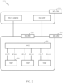
- FIG. 1 illustrates an example wireless network 100, such as a new radio (NR) or 5G network, in which aspects of the present disclosure may be performed, for example, for improving device discovery in a multi-slice network.
- the network 100 may be a multi-slice network, each slice defines as a composition of adequately configured network functions, network applications, and underlying cloud infrastructures that are bundled together to meet the requirement of a specific use case or business model.
- the wireless network 100 may include a number of BSs 110 and other network entities.
- a BS may be a station that communicates with UEs.
- Each BS 110 may provide communication coverage for a particular geographic area.
- the term "cell" can refer to a coverage area of a Node B and/or a Node B subsystem serving this coverage area, depending on the context in which the term is used.
- the term "cell” and eNB, Node B, 5G NB, AP, NR BS, NR BS, BS, or TRP may be interchangeable.
- a cell may not necessarily be stationary, and the geographic area of the cell may move according to the location of a mobile base station.
- the base stations may be interconnected to one another and/or to one or more other base stations or network nodes (not shown) in the wireless network 100 through various types of backhaul interfaces such as a direct physical connection, a virtual network, or the like using any suitable transport network.
- any number of wireless networks may be deployed in a given geographic area.
- Each wireless network may support a particular radio access technology (RAT) and may operate on one or more frequencies.
- a RAT may also be referred to as a radio technology, an air interface, etc.
- a frequency may also be referred to as a carrier, a frequency channel, etc.
- Each frequency may support a single RAT in a given geographic area in order to avoid interference between wireless networks of different RATs.
- NR or 5G RAT networks may be deployed, employing a multi-slice network architecture.
- a BS may provide communication coverage for a macro cell, a pico cell, a femto cell, and/or other types of cell.
- a macro cell may cover a relatively large geographic area (e.g., several kilometers in radius) and may allow unrestricted access by UEs with service subscription.
- a pico cell may cover a relatively small geographic area and may allow unrestricted access by UEs with service subscription.
- a femto cell may cover a relatively small geographic area (e.g., a home) and may allow restricted access by UEs having association with the femto cell (e.g., UEs in a Closed Subscriber Group (CSG), UEs for users in the home, etc.).
- CSG Closed Subscriber Group
- a BS for a macro cell may be referred to as a macro BS.
- a BS for a pico cell may be referred to as a pico BS.
- a BS for a femto cell may be referred to as a femto BS or a home BS.
- the BSs 110a, 110b and 110c may be macro BSs for the macro cells 102a, 102b and 102c, respectively.
- the BS 110x may be a pico BS for a pico cell 102x.
- the BSs 110y and 110z may be femto BS for the femto cells 102y and 102z, respectively.
- a BS may support one or multiple (e.g., three) cells.
- the wireless network 100 may also include relay stations.
- a relay station is a station that receives a transmission of data and/or other information from an upstream station (e.g., a BS or a UE) and sends a transmission of the data and/or other information to a downstream station (e.g., a UE or a BS).
- a relay station may also be a UE that relays transmissions for other UEs.
- a relay station 110r may communicate with the BS 110a and a UE 120r in order to facilitate communication between the BS 110a and the UE 120r.
- a relay station may also be referred to as a relay BS, a relay, etc.
- the wireless network 100 may be a heterogeneous network that includes BSs of different types, e.g., macro BS, pico BS, femto BS, relays, etc. These different types of BSs may have different transmit power levels, different coverage areas, and different impact on interference in the wireless network 100.
- macro BS may have a high transmit power level (e.g., 20 Watts) whereas pico BS, femto BS, and relays may have a lower transmit power level (e.g., 1 Watt).
- the wireless network 100 may support synchronous or asynchronous operation.
- the BSs may have similar frame timing, and transmissions from different BSs may be approximately aligned in time.
- the BSs may have different frame timing, and transmissions from different BSs may not be aligned in time.
- the techniques described herein may be used for both synchronous and asynchronous operation.
- a network controller 130 may couple to a set of BSs and provide coordination and control for these BSs.
- the network controller 130 may communicate with the BSs 110 via a backhaul.
- the BSs 110 may also communicate with one another, e.g., directly or indirectly via wireless or wireline backhaul.
- the UEs 120 may be dispersed throughout the wireless network 100, and each UE may be stationary or mobile.
- a UE may also be referred to as a mobile station, a terminal, an access terminal, a subscriber unit, a station, a Customer Premises Equipment (CPE), a cellular phone, a smart phone, a personal digital assistant (PDA), a wireless modem, a wireless communication device, a handheld device, a laptop computer, a cordless phone, a wireless local loop (WLL) station, a tablet, a camera, a gaming device, a netbook, a smartbook, an ultrabook, a medical device or medical equipment, a biometric sensor/device, a wearable device such as a smart watch, smart clothing, smart glasses, a smart wrist band, smart jewelry (e.g., a smart ring, a smart bracelet, etc.), an entertainment device (e.g., a music device, a video device, a
- CPE Customer Premises Equipment
- Some UEs may be considered evolved or machine-type communication (MTC) devices or evolved MTC (eMTC) devices.
- MTC and eMTC UEs include, for example, robots, drones, remote devices, sensors, meters, monitors, location tags, etc., that may communicate with a BS, another device (e.g., remote device), or some other entity.
- a wireless node may provide, for example, connectivity for or to a network (e.g., a wide area network such as Internet or a cellular network) via a wired or wireless communication link.
- Some UEs may be considered Internet-of-Things (IoT) devices.
- IoT Internet-of-Things
- a solid line with double arrows indicates desired transmissions between a UE and a serving BS, which is a BS designated to serve the UE on the downlink and/or uplink.
- a dashed line with double arrows indicates interfering transmissions between a UE and a BS.
- Certain wireless networks utilize orthogonal frequency division multiplexing (OFDM) on the downlink and single-carrier frequency division multiplexing (SC-FDM) on the uplink.
- OFDM and SC-FDM partition the system bandwidth into multiple (K) orthogonal subcarriers, which are also commonly referred to as tones, bins, etc.
- K orthogonal subcarriers
- Each subcarrier may be modulated with data.
- modulation symbols are sent in the frequency domain with OFDM and in the time domain with SC-FDM.
- the spacing between adjacent subcarriers may be fixed, and the total number of subcarriers (K) may be dependent on the system bandwidth.
- the spacing of the subcarriers may be 15 kHz and the minimum resource allocation (called a 'resource block') may be 12 subcarriers (or 180 kHz). Consequently, the nominal FFT size may be equal to 128, 256, 512, 1024 or 2048 for system bandwidth of 1.25, 2.5, 5, 10 or 20 megahertz (MHz), respectively.
- the system bandwidth may also be partitioned into subbands. For example, a subband may cover 1.08 MHz (i.e., 6 resource blocks), and there may be 1, 2, 4, 8 or 16 subbands for system bandwidth of 1.25, 2.5, 5, 10 or 20 MHz, respectively.
- aspects of the examples described herein may be associated with LTE technologies, aspects of the present disclosure may be applicable with other wireless communications systems, such as NR/5G.
- NR may utilize OFDM with a CP on the uplink and downlink and include support for half-duplex operation using TDD.
- a single component carrier bandwidth of 100 MHz may be supported.
- NR resource blocks may span 12 sub-carriers with a subcarrier bandwidth of 75 kHz over a 0.1ms duration.
- Each radio frame may consist of 50 subframes with a length of 10ms. Consequently, each subframe may have a length of 0.2ms.
- Each subframe may indicate a link direction (i.e., DL or UL) for data transmission and the link direction for each subframe may be dynamically switched.
- Each subframe may include DL/UL data as well as DL/UL control data.
- UL and DL subframes for NR may be as described in more detail below with reference to FIGs. 9 and 10 .
- Beamforming may be supported and beam direction may be dynamically configured.
- MIMO transmissions with precoding may also be supported.
- MIMO configurations in the DL may support up to 8 transmit antennas with multi-layer DL transmissions up to 8 streams and up to 2 streams per UE.
- Multi-layer transmissions with up to 2 streams per UE may be supported.
- Aggregation of multiple cells may be supported with up to 8 serving cells.
- NR may support a different air interface, other than an OFDM-based.
- NR networks may include entities such CUs and/or DUs.
- a scheduling entity e.g., a base station
- the scheduling entity may be responsible for scheduling, assigning, reconfiguring, and releasing resources for one or more subordinate entities. That is, for scheduled communication, subordinate entities utilize resources allocated by the scheduling entity.
- Base stations are not the only entities that may function as a scheduling entity. That is, in some examples, a UE may function as a scheduling entity, scheduling resources for one or more subordinate entities (e.g., one or more other UEs).
- the UE is functioning as a scheduling entity, and other UEs utilize resources scheduled by the UE for wireless communication.
- a UE may function as a scheduling entity in a peer-to-peer (P2P) network, and/or in a mesh network.
- P2P peer-to-peer
- UEs may optionally communicate directly with one another in addition to communicating with the scheduling entity.
- a scheduling entity and one or more subordinate entities may communicate utilizing the scheduled resources.
- a RAN may include a CU and DUs.
- a NR BS e.g., gNB, 5G Node B, Node B, transmission reception point (TRP), access point (AP)
- NR cells can be configured as access cell (ACells) or data only cells (DCells).
- the RAN e.g., a central unit or distributed unit
- DCells may be cells used for carrier aggregation or dual connectivity, but not used for initial access, cell selection/reselection, or handover. In some cases DCells may not transmit synchronization signals-in some case cases DCells may transmit SS.
- NR BSs may transmit downlink signals to UEs indicating the cell type. Based on the cell type indication, the UE may communicate with the NR BS. For example, the UE may determine NR BSs to consider for cell selection, access, handover, and/or measurement based on the indicated cell type.
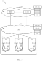
- FIG. 2 illustrates an example logical architecture of a distributed radio access network (RAN) 200, which may be implemented in the wireless communication system illustrated in FIG. 1 .
- a 5G access node 206 may include an access node controller (ANC) 202.
- the ANC may be a central unit (CU) of the distributed RAN 200.
- the backhaul interface to the next generation core network (NG-CN) 204 may terminate at the ANC.
- the backhaul interface to neighboring next generation access nodes (NG-ANs) may terminate at the ANC.
- the ANC may include one or more TRPs 208 (which may also be referred to as BSs, NR BSs, Node Bs, 5G NBs, APs, or some other term). As described above, a TRP may be used interchangeably with "cell.”
- the TRPs 208 may be a DU.
- the TRPs may be connected to one ANC (ANC 202) or more than one ANC (not illustrated).
- ANC ANC
- RaaS radio as a service
- a TRP may include one or more antenna ports.
- the TRPs may be configured to individually (e.g., dynamic selection) or jointly (e.g., joint transmission) serve traffic to a UE.
- the local architecture 200 may be used to illustrate fronthaul definition.
- the architecture may be defined that support fronthauling solutions across different deployment types.
- the architecture may be based on transmit network capabilities (e.g., bandwidth, latency, and/or jitter).
- the architecture may share features and/or components with LTE.
- the next generation AN (NG-AN) 210 may support dual connectivity with NR.
- the NG-AN may share a common fronthaul for LTE and NR.
- the architecture may enable cooperation between and among TRPs 208. For example, cooperation may be preset within a TRP and/or across TRPs via the ANC 202. According to aspects, no inter-TRP interface may be needed/present.
- a dynamic configuration of split logical functions may be present within the architecture 200.
- the Radio Resource Control (RRC) layer, Packet Data Convergence Protocol (PDCP) layer, Radio Link Control (RLC) layer, Medium Access Control (MAC) layer, and a Physical (PHY) layers may be adaptably placed at the DU or CU (e.g., TRP or ANC, respectively).
- a BS may include a central unit (CU) (e.g., ANC 202) and/or one or more distributed units (e.g., one or more TRPs 208).
- CU central unit
- distributed units e.g., one or more TRPs 208.
- FIG. 3 illustrates an example physical architecture of a distributed RAN 300, according to aspects of the present disclosure.
- a centralized core network unit (C-CU) 302 may host core network functions.
- the C-CU may be centrally deployed.
- C-CU functionality may be offloaded (e.g., to advanced wireless services (AWS)), in an effort to handle peak capacity.
- AWS advanced wireless services
- a centralized RAN unit (C-RU) 304 may host one or more ANC functions.
- the C-RU may host core network functions locally.
- the C-RU may have distributed deployment.
- the C-RU may be closer to the network edge.
- a DU 306 may host one or more TRPs (edge node (EN), an edge unit (EU), a radio head (RH), a smart radio head (SRH), or the like).
- the DU may be located at edges of the network with radio frequency (RF) functionality.
- RF radio frequency
- FIG. 4 illustrates example components of the BS 110 and UE 120 illustrated in FIG. 1 , which may be used to implement aspects of the present disclosure.
- the BS may include a TRP.
- One or more components of the BS 110 and UE 120 may be used to practice aspects of the present disclosure.
- antennas 452, Tx/Rx 222, processors 466, 458, 464, and/or controller/processor 480 of the UE 120 and/or antennas 434, processors 460, 420, 438, and/or controller/processor 440 of the BS 110 may be used to perform the operations described herein and illustrated with reference to FIG. 16 .
- the base station 110 may be the macro BS 110c in FIG. 1 , and the UE 120 may be the UE 120y.
- the base station 110 may also be a base station of some other type.
- the base station 110 may be equipped with antennas 434a through 434t, and the UE 120 may be equipped with antennas 452a through 452r.
- a transmit processor 420 may receive data from a data source 412 and control information from a controller/processor 440.
- the control information may be for the Physical Broadcast Channel (PBCH), Physical Control Format Indicator Channel (PCFICH), Physical Hybrid ARQ Indicator Channel (PHICH), Physical Downlink Control Channel (PDCCH), etc.
- the data may be for the Physical Downlink Shared Channel (PDSCH), etc.
- the processor 420 may process (e.g., encode and symbol map) the data and control information to obtain data symbols and control symbols, respectively.
- the processor 420 may also generate reference symbols, e.g., for the PSS, SSS, and cell-specific reference signal.
- a transmit (TX) multiple-input multiple-output (MIMO) processor 430 may perform spatial processing (e.g., precoding) on the data symbols, the control symbols, and/or the reference symbols, if applicable, and may provide output symbol streams to the modulators (MODs) 432a through 432t.
- Each modulator 432 may process a respective output symbol stream (e.g., for OFDM, etc.) to obtain an output sample stream.
- Each modulator 432 may further process (e.g., convert to analog, amplify, filter, and upconvert) the output sample stream to obtain a downlink signal.
- Downlink signals from modulators 432a through 432t may be transmitted via the antennas 434a through 434t, respectively.
- the antennas 452a through 452r may receive the downlink signals from the base station 110 and may provide received signals to the demodulators (DEMODs) 454a through 454r, respectively.
- Each demodulator 454 may condition (e.g., filter, amplify, downconvert, and digitize) a respective received signal to obtain input samples.
- Each demodulator 454 may further process the input samples (e.g., for OFDM, etc.) to obtain received symbols.
- a MIMO detector 456 may obtain received symbols from all the demodulators 454a through 454r, perform MIMO detection on the received symbols if applicable, and provide detected symbols.
- a receive processor 458 may process (e.g., demodulate, deinterleave, and decode) the detected symbols, provide decoded data for the UE 120 to a data sink 460, and provide decoded control information to a controller/processor 480.
- a transmit processor 464 may receive and process data (e.g., for the Physical Uplink Shared Channel (PUSCH)) from a data source 462 and control information (e.g., for the Physical Uplink Control Channel (PUCCH) from the controller/processor 480.
- the transmit processor 464 may also generate reference symbols for a reference signal.
- the symbols from the transmit processor 464 may be precoded by a TX MIMO processor 466 if applicable, further processed by the demodulators 454a through 454r (e.g., for SC-FDM, etc.), and transmitted to the base station 110.
- the uplink signals from the UE 120 may be received by the antennas 434, processed by the modulators 432, detected by a MIMO detector 436 if applicable, and further processed by a receive processor 438 to obtain decoded data and control information sent by the UE 120.
- the receive processor 438 may provide the decoded data to a data sink 439 and the decoded control information to the controller/processor 440.
- the controllers/processors 440 and 480 may direct the operation at the base station 110 and the UE 120, respectively.
- the processor 440 and/or other processors and modules at the base station 110 may perform or direct, e.g., the execution of the functional blocks illustrated in FIG. 6 , and/or other processes for the techniques described herein.
- the processor 480 and/or other processors and modules at the UE 120 may also perform or direct, e.g., the execution of the functional blocks illustrated in FIG. 7 , and/or other processes for the techniques described herein.
- the memories 442 and 482 may store data and program codes for the BS 110 and the UE 120, respectively.
- a scheduler 444 may schedule UEs for data transmission on the downlink and/or uplink.
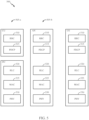
- FIG. 5 illustrates a diagram 500 showing examples for implementing a communications protocol stack, according to aspects of the present disclosure.
- the illustrated communications protocol stacks may be implemented by devices operating in a 5G system (e.g., a system that supports uplink-based mobility).
- Diagram 500 illustrates a communications protocol stack including a Radio Resource Control (RRC) layer 510, a Packet Data Convergence Protocol (PDCP) layer 515, a Radio Link Control (RLC) layer 520, a Medium Access Control (MAC) layer 525, and a Physical (PHY) layer 530.
- RRC Radio Resource Control
- PDCP Packet Data Convergence Protocol
- RLC Radio Link Control
- MAC Medium Access Control
- PHY Physical
- the layers of a protocol stack may be implemented as separate modules of software, portions of a processor or ASIC, portions of non-collocated devices connected by a communications link, or various combinations thereof. Collocated and non-collocated implementations may be used, for example, in a
- a first option 505--a shows a split implementation of a protocol stack, in which implementation of the protocol stack is split between a centralized network access device (e.g., an ANC 202 in FIG. 2 ) and distributed network access device (e.g., DU 208 in FIG. 2 ).
- a centralized network access device e.g., an ANC 202 in FIG. 2
- distributed network access device e.g., DU 208 in FIG. 2
- an RRC layer 510 and a PDCP layer 515 may be implemented by the central unit
- an RLC layer 520, a MAC layer 525, and a PHY layer 530 may be implemented by the DU.
- the CU and the DU may be collocated or non-collocated.
- the first option 505-a may be useful in a macro cell, micro cell, or pico cell deployment.
- a second option 505--b shows a unified implementation of a protocol stack, in which the protocol stack is implemented in a single network access device (e.g., access node (AN), new radio base station (NR BS), a new radio Node-B (NR NB), a network node (NN), or the like.).
- the RRC layer 510, the PDCP layer 515, the RLC layer 520, the MAC layer 525, and the PHY layer 530 may each be implemented by the AN.
- the second option 505-b may be useful in a femto cell deployment.
- a UE may implement an entire protocol stack (e.g., the RRC layer 510, the PDCP layer 515, the RLC layer 520, the MAC layer 525, and the PHY layer 530).
- an entire protocol stack e.g., the RRC layer 510, the PDCP layer 515, the RLC layer 520, the MAC layer 525, and the PHY layer 530.
- FIG. 6 illustrates various components that may be utilized in a wireless communications device 602 that may be employed within the wireless communication system from FIG. 1 .
- the wireless communications device 602 is an example of a device that may be configured to implement the various methods described herein.
- the wireless communications device 602 may be an BS 110 from FIG. 1 or any of user equipments 120.
- the wireless communications device 602 may include a processor 604 which controls operation of the wireless communications device 602.
- the processor 604 may also be referred to as a central processing unit (CPU).
- Memory 606 which may include both read-only memory (ROM) and random access memory (RAM), provides instructions and data to the processor 604.
- a portion of the memory 606 may also include non-volatile random access memory (NVRAM).
- the processor 604 typically performs logical and arithmetic operations based on program instructions stored within the memory 606.
- the instructions in the memory 606 may be executable to implement the methods described herein.
- the wireless communications device 602 may also include a housing 608 that may include a transmitter 610 and a receiver 612 to allow transmission and reception of data between the wireless device 602 and a remote location.
- the transmitter 610 and receiver 612 may be combined into a transceiver 614.
- a single or a plurality of transmit antennas 616 may be attached to the housing 608 and electrically coupled to the transceiver 614.
- the wireless communications device 602 may also include (not shown) multiple transmitters, multiple receivers, and multiple transceivers.
- the wireless communications device 602 may also include a signal detector 618 that may be used in an effort to detect and quantify the level of signals received by the transceiver 614.
- the signal detector 618 may detect such signals as total energy, energy per subcarrier per symbol, power spectral density and other signals.
- the wireless communications device 602 may also include a digital signal processor (DSP) 620 for use in processing signals.
- DSP digital signal processor
- the wireless communications device 602 may also include an encoder 622 for use in encoding signals for transmission.
- the encoder may also store the encoded signals in a circular buffer (not shown) and perform rate matching on the encoded signals (e.g., by implementing operations 1600, shown in FIG. 16 ).
- the wireless communication device 602 may include a decoder 624 for use in decoding received signals.
- the various components of the wireless communications device 602 may be coupled together by a bus system 626, which may include a power bus, a control signal bus, and a status signal bus in addition to a data bus.
- the processor 604 may be configured to access instructions stored in the memory 606 to perform connectionless access, in accordance with aspects of the present disclosure discussed below.
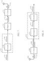
- FIG. 7 is a simplified block diagram illustrating an encoder, in accordance with certain aspects of the present disclosure.
- FIG. 7 illustrates a portion of a radio frequency (RF) modem 704 that may be configured to provide an encoded message for wireless transmission (e.g., using polar codes described below).
- RF radio frequency
- an encoder 706 in a wireless device receives a message 702 for transmission.
- the message 702 may contain data and/or encoded voice or other content directed to the receiving device.
- the encoder 706 encodes the message using a suitable modulation and coding scheme (MCS), typically selected based on a configuration defined by the BS 110 or another network entity.
- MCS modulation and coding scheme
- the encoded bitstream 708 is then stored in circular buffer and rate-matching is performed on the stored encoded bitstream, for example, according to aspects of the present disclosure described in more detail below.
- the encoded bitstream 708 may then be provided to a mapper 710 that generates a sequence of TX symbols 712 that are modulated, amplified and otherwise processed by TX chain 714 to produce an RF signal 716 for transmission through antenna 718.
- FIG. 8 is a simplified block diagram illustrating a decoder, in accordance with certain aspects of the present disclosure.
- FIG. 8 illustrates a portion of a RF modem 810 that may be configured to receive and decode a wirelessly transmitted signal including an encoded message (e.g., a message encoded using a polar code as described below).
- the modem 810 receiving the signal may reside at a user equipment, at a base station, or at any other suitable apparatus or means for carrying out the described functions.
- An antenna 802 provides an RF signal 716 (i.e., the RF signal produced in FIG. 7 ) to an access terminal (e.g., UE 120).
- An RX chain 806 processes and demodulates the RF signal 716 and may provide a sequence of symbols 808 to a demapper 812, which produces a bitstream 814 representative of the encoded message.
- a decoder 816 may then be used to decode m-bit information strings from a bitstream that has been encoded using a coding scheme (e.g., a Polar code).
- the decoder 816 may comprise a Viterbi decoder, an algebraic decoder, a butterfly decoder, or another suitable decoder.
- a Viterbi decoder employs the well-known Viterbi algorithm to find the most likely sequence of signaling states (the Viterbi path) that corresponds to a received bitstream 814.
- the bitstream 814 may be decoded based on a statistical analysis of LLRs calculated for the bitstream 814.
- a Viterbi decoder may compare and select the correct Viterbi path that defines a sequence of signaling states using a likelihood ratio test to generate LLRs from the bitstream 814.
- Likelihood ratios can be used to statistically compare the fit of a plurality of candidate Viterbi paths using a likelihood ratio test that compares the logarithm of a likelihood ratio for each candidate Viterbi path (i.e. the LLR) to determine which path is more likely to account for the sequence of symbols that produced the bitstream 814.
- the decoder 816 may then decode the bitstream 814 based on the LLRs to determine the message 818 containing data and/or encoded voice or other content transmitted from the base station (e.g., BS 110).
- FIG. 9 is a diagram 900 showing an example of a DL-centric subframe, which may be used by one or more devices (e.g., BS 110 and/or UE 120) to communicate in the wireless network 100.
- the DL-centric subframe may include a control portion 902.
- the control portion 902 may exist in the initial or beginning portion of the DL-centric subframe.
- the control portion 902 may include various scheduling information and/or control information corresponding to various portions of the DL-centric subframe.
- the control portion 902 may be a physical DL control channel (PDCCH), as indicated in FIG. 9 .
- the DL-centric subframe may also include a DL data portion 904.
- the DL data portion 904 may sometimes be referred to as the payload of the DL-centric subframe.
- the DL data portion 904 may include the communication resources utilized to communicate DL data from the scheduling entity (e.g., UE or BS) to the subordinate entity (e.g., UE).
- the DL data portion 904 may be a physical DL shared channel (PDSCH).
- PDSCH physical DL shared channel
- the DL-centric subframe may also include a common UL portion 906.
- the common UL portion 906 may sometimes be referred to as an UL burst, a common UL burst, and/or various other suitable terms.
- the common UL portion 906 may include feedback information corresponding to various other portions of the DL-centric subframe.
- the common UL portion 906 may include feedback information corresponding to the control portion 902.
- Non-limiting examples of feedback information may include an ACK signal, a NACK signal, a HARQ indicator, and/or various other suitable types of information.
- the common UL portion 906 may include additional or alternative information, such as information pertaining to random access channel (RACH) procedures, scheduling requests (SRs), and various other suitable types of information.
- RACH random access channel
- SRs scheduling requests
- the end of the DL data portion 904 may be separated in time from the beginning of the common UL portion 906.
- This time separation may sometimes be referred to as a gap, a guard period, a guard interval, and/or various other suitable terms.
- This separation provides time for the switch-over from DL communication (e.g., reception operation by the subordinate entity (e.g., UE)) to UL communication (e.g., transmission by the subordinate entity (e.g., UE)).
- DL communication e.g., reception operation by the subordinate entity (e.g., UE)
- UL communication e.g., transmission by the subordinate entity (e.g., UE)
- FIG. 10 is a diagram 1000 showing an example of an UL-centric subframe, which may be used by one or more devices (e.g., BS 110 and/or UE 120) to communicate in the wireless network 100.
- the UL -centric subframe may include a control portion 1002.
- the control portion 1002 may exist in the initial or beginning portion of the UL-centric subframe.
- the control portion 1002 in FIG. 10 may be similar to the control portion described above with reference to FIG. 9 .
- the UL-centric subframe may also include an UL data portion 1004.
- the UL data portion 1004 may sometimes be referred to as the payload of the UL-centric subframe.
- the UL portion may refer to the communication resources utilized to communicate UL data from the subordinate entity (e.g., UE) to the scheduling entity (e.g., UE or BS).
- the control portion 1002 may be a physical DL control channel (PDCCH).
- the end of the control portion 1002 may be separated in time from the beginning of the UL data portion 1004. This time separation may sometimes be referred to as a gap, guard period, guard interval, and/or various other suitable terms. This separation provides time for the switch-over from DL communication (e.g., reception operation by the scheduling entity) to UL communication (e.g., transmission by the scheduling entity).
- the UL-centric subframe may also include a common UL portion 1006.
- the common UL portion 1006 in FIG. 10 may be similar to the common UL portion 1006 described above with reference to FIG. 10 .
- the common UL portion 1006 may additional or alternative include information pertaining to channel quality indicator (CQI), sounding reference signals (SRSs), and various other suitable types of information.
- CQI channel quality indicator
- SRSs sounding reference signals
- One of ordinary skill in the art will understand that the foregoing is merely one example of an UL-centric subframe and alternative structures having similar features may exist without necessarily deviating from the aspects described herein.
- two or more subordinate entities may communicate with each other using sidelink signals.
- Real-world applications of such sidelink communications may include public safety, proximity services, UE-to-network relaying, vehicle-to-vehicle (V2V) communications, Internet of Everything (IoE) communications, IoT communications, mission-critical mesh, and/or various other suitable applications.
- a sidelink signal may refer to a signal communicated from one subordinate entity (e.g., UE1) to another subordinate entity (e.g., UE2) without relaying that communication through the scheduling entity (e.g., UE or BS), even though the scheduling entity may be utilized for scheduling and/or control purposes.
- the sidelink signals may be communicated using a licensed spectrum (unlike wireless local area networks, which typically use an unlicensed spectrum).
- a UE may operate in various radio resource configurations, including a configuration associated with transmitting pilots using a dedicated set of resources (e.g., a radio resource control (RRC) dedicated state, etc.) or a configuration associated with transmitting pilots using a common set of resources (e.g., an RRC common state, etc.).
- RRC radio resource control
- the UE may select a dedicated set of resources for transmitting a pilot signal to a network.
- the UE may select a common set of resources for transmitting a pilot signal to the network.
- a pilot signal transmitted by the UE may be received by one or more network access devices, such as an AN, or a DU, or portions thereof.
- Each receiving network access device may be configured to receive and measure pilot signals transmitted on the common set of resources, and also receive and measure pilot signals transmitted on dedicated sets of resources allocated to the UEs for which the network access device is a member of a monitoring set of network access devices for the UE.
- One or more of the receiving network access devices, or a CU to which receiving network access device(s) transmit the measurements of the pilot signals may use the measurements to identify serving cells for the UEs, or to initiate a change of serving cell for one or more of the UEs.
- Polar codes are used to encode a stream of bits for transmission.
- Polar codes are the first provably capacity-achieving coding scheme with almost linear (in block length) encoding and decoding complexity.
- Polar codes are widely considered as a candidate for error-correction in the next-generation wireless systems.
- Polar codes have many desirable properties such as deterministic construction (e.g., based on a fast Hadamard transform), very low and predictable error floors, and simple successive-cancellation (SC) based decoding.
- a number of input bits e.g., information bits
- every estimated bit, û i has a predetermined error probability given that bits u 0 i-1 were correctly decoded, that tends towards either 0 or 0.5. Moreover, the proportion of estimated bits with a low error probability tends towards the capacity of the underlying channel.
- Polar codes exploit a phenomenon called channel polarization by using the most reliable K bits to transmit information, while setting, or freezing, the remaining (N-K) bits to a predetermined value, such as 0, for example as explained below.
- polar codes transform the channel into N parallel "virtual" channels for the N information bits. If C is the capacity of the channel, then there are almost N*C channels which are completely noise free and there are N(1 - C) channels which are completely noisy.
- the basic polar coding scheme then involves freezing (i.e., not transmitting) the information bits to be sent along the completely noisy channel and sending information only along the perfect channels. For short-to-medium N, this polarization may not be complete in the sense there could be several channels which are neither completely useless nor completely noise free (i.e., channels that are in transition). Depending on the rate of transmission, these channels in the transition are either frozen or they are used for transmission.
- Rate matching is a process whereby the number of bits to be transmitted is matched to the available bandwidth of the number of bits allowed to be transmitted (e.g., the number of bits that can be carried in an allocation of transmission resources).
- the amount of data to be transmitted is less than the available bandwidth, in which case all the data to be transmitted (and one or more copies of the data) will be transmitted (a technique called repetition).
- the amount of data to be transmitted exceeds the available bandwidth, in which case a certain portion of the data to be transmitted will be omitted from the transmission using a technique called puncturing and/or a technique called shortening.
- FIG. 11 illustrates an example process 1100 for polar encoding and rate matching information, according to aspects of the present disclosure.
- Information bits 1102 may be encoded with a polar encoder 1104 to produce encoded bits at 1106.
- the encoded bits may be collected into a circular buffer (e.g., a virtual circular buffer implemented in memory of a device) at 1108. Some of the encoded bits are selected for puncturing, shortening, or repetition at 1110.
- the stream of encoded bits that is produced is then interleaved at 1112 and provided to a transmit chain for transmission.
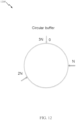
- FIG. 12 illustrates an exemplary circular buffer 1200, according to aspects of the present disclosure not falling under the scope of the claims.
- a tail biting convolutional code (TBCC) of rate 1/3 may be used for rate matching control channels and other types of channels, which is typically performed using a circular buffer.
- the bits of the channel may be encoded using three polynomials. Still in the example, after encoding a stream of bits, the resultant encoded bits from the three polynomials are put into the circular buffer one by one. For example, with reference to FIG. 12 , code bits from the first polynomial are placed in the circular buffer in the range of [0, N-1]. Further, code bits from the second polynomial are placed in the circular buffer in the range of [N, 2N-1], and code bits from the third polynomial are placed in the circular buffer in the range of [2N, 3N-1].
- polar codes of size may be used to encode a stream of bits for transmission.
- rate matching scheme e.g., for TBCC codes
- performance loss when used with polar codes, for example, when the size of the circular buffer is not a power of 2 (e.g., the block length constraint of polar codes).
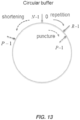
- rate-matching may involve puncturing, repeating, or shortening certain bits of the encoded bits stored in the circular buffer, for example, as illustrated in FIG. 13 .
- puncturing, repeating, or shortening may be determined by the wireless communications device based, at least in part, on the allocated coded block size, M, and the target coded block size, N.
- the wireless communications device performs rate matching by repeating M-N (M minus N) encoded bits (e.g., R bits ) based on the Polar code of size N starting from the zeroth position in the circular buffer and proceeding clockwise around the circular buffer until position R bits -1 in the circular buffer, for example, as illustrated in FIG. 13 .
- R bits may be repeated at the end of the stream of encoded bits stored in the circular buffer.
- N-M encoded bits e.g., P bits
- the wireless communications device shortens N-M encoded bits (e.g., P bits ) based on the Polar code N, starting from position N-1 in the circular buffer and proceeding counterclockwise around the circular buffer, for example, as illustrated in FIG. 13 .
- N-M encoded bits e.g., P bits
- FIG. 14 is a diagram 1400 illustrating a block-level interlacing technique for rate matching, according to previously known techniques.
- the polar encoder 1402 uses a polar code of size N to encode a stream of bits to generate a stream of encoded output bits 1404. That stream of encoded output bits is divided into 16 blocks at 1406. The blocks are then interlaced by being placed in a circular buffer in a different order at 1408. An allocation of transmission resources of size M is allocated for transmission of the stream of bits. If M is less than N, then some of the blocks may be punctured, as shown at 1410, or shortened, as shown at 1412. If M is greater than N, then some of the blocks may be repeated, as shown at 1414.
- This technique of rate matching has a granularity of N/16 (e.g., an entire block of size N/16 may be punctured or shortened), and this can be very large when N is very large, which may be a drawback in some cases.
- FIG. 15 is a diagram 1500 illustrating a bit-level interlacing technique for rate matching, according to previously known techniques.
- the polar encoder 1502 uses a polar code of size N to encode a stream of K bits (e.g., information bits and a CRC) to generate a stream of encoded output bits 1504. That stream of encoded output bits is divided into 4 blocks at 1506. The bits of the middle two blocks are then interlaced by at 1508.
- An allocation of transmission resources (e.g., a coded bit length) of size M is allocated for transmission of the stream of bits. If M is greater than N, then some of the bits may be repeated, as shown at 1510. If M is less than N, then some of the bits may be punctured, as shown at 1512, or shortened, as shown at 1514. This technique of rate matching may have decreased performance when a number of bits to puncture or shorten is greater than N;4.
- aspects of the present disclosure propose an efficient rate-matching scheme for channels using polar codes.
- bits are selected for modification (e.g., puncturing and/or shortening) based on row weights of a Hadamard matrix.
- bits corresponding to the smallest row weights may be punctured to provide better performance than previously known techniques.
- bits corresponding to the largest row weights may be shortened to provide better performance than previously known techniques.
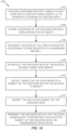
- FIG. 16 illustrates example operations 1600 for wireless communications, for example, for rate-mating of a control channel using polar codes.
- Operations 1600 may be performed by a wireless communications device, such as a base station (BS 110), user equipment 120, and/or wireless communications device 602.
- BS 110 base station
- user equipment 120 user equipment 120
- Operations 1600 begin at 1602 by encoding K information bits using a polar code with a mother code length, N, to generate a stream of encoded bits.
- the wireless communications device stores a portion of the encoded bits in a circular buffer of size N.
- the wireless communications device reorders P blocks of the circular buffer according to row weights of a Hadamard matrix J.
- the wireless communications device interlaces the encoded bits of the blocks having a same row weight.
- the wireless communications device selects, based on the row weights, a subset of the encoded bits in the blocks to modify.
- the wireless communications device modifies the selected subset of the encoded bits.
- the wireless communications device transmits the encoded bits in the P blocks, subsequent to modifying the selected subset of the encoded bits, via transmission resources.
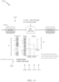
- FIG. 17 is a diagram 1700 of an exemplary algorithm for determining bits to be punctured and/or shortened for rate-matching, in accordance with certain aspects of the present disclosure.
- the encoded (e.g., polar encoded) bits are represented at 1702.
- a wireless communications device divides the mother code length N bits into P blocks, each containing N/P bits. i.e., block! has bits 0 through (N/P)-1, block2 has bits N/P through (N/P)*2-1, etc.
- FIG. 17 is illustrated using a typical value of P of 8, but other values of P that are integral powers of 2 may be used.
- the wireless communications device reorders the blocks according to the row weights of a Hadamard matrix.
- the Hadamard matrix J is constructed with order of log 2 (P).
- the row weights of J may be calculated by adding the values in each row of J.
- the Hadamard matrix of order 3 is reproduced below, with a table showing the row weights.
- sorting the blocks according to row weights of the Hadamard matrix J results in the fifth block being placed before the fourth block.
- the blocks remain in the natural order for blocks corresponding to rows with a same row weight.
- the wireless communications device performs a bit-level interlace of the bits, after the block reordering at 1706.
- the interlacing interlaces bits of blocks having a same row weight.
- the bits from blocks 2, 3, and 5 are interlaced
- the bits from blocks 4, 6, and 7 are interlaced.
- bits selected for puncturing are the 1st N-M bits from 1708. If bits are to be shortened, the bits selected for shortening are the end N-M bits from 1708. The bits selected for shortening are labeled at 1712.
- the modification operation in block 1612 of FIG. 16 may be a repetition operation.
- the wireless communications device may select the first N-M bits in the blocks for repetition.
- row weights of a Hadamard matrix of order 4 are shown in the table below. Row Row weight 1 1 2 2 3 2 4 4 5 2 6 4 7 4 8 8 9 2 10 4 11 4 12 8 13 4 14 8 15 8 16 16
- the methods disclosed herein comprise one or more steps or actions for achieving the described method.
- the method steps and/or actions may be interchanged with one another without departing from the scope of the claims.
- the order and/or use of specific steps and/or actions may be modified without departing from the scope of the claims.
- the techniques described above provide an efficient rate-matching algorithm(s) with a good trade-off between decoding complexity and decoding performance. For example, by using the techniques described above to puncture, repeat, or shorten encoded bits before transmission, decoding complexity and latency at a receiving device may be reduced because these bits do not need to be decoded, which, in turn, saves processing resources and power at the receiving device.
- a phrase referring to "at least one of" a list of items refers to any combination of those items, including single members.
- "at least one of: a, b, or c” is intended to cover a, b, c, a-b, a-c, b-c, and a-b-c, as well as any combination with multiples of the same element (e.g., a-a, a-a-a, a-a-b, a-a-c, a-b-b, a-c-c, b-b, b-b-b, b-b-c, c-c, and c-c-c or any other ordering of a, b, and c).
- determining encompasses a wide variety of actions. For example, “determining” may include calculating, computing, processing, deriving, investigating, looking up (e.g., looking up in a table, a database or another data structure), ascertaining and the like. Also, “determining” may include receiving (e.g., receiving information), accessing (e.g., accessing data in a memory) and the like. Also, “determining” may include resolving, selecting, choosing, establishing and the like.
- a device may have an interface to output a frame for transmission.
- a processor may output a frame, via a bus interface, to an RF front end for transmission.
- a device may have an interface to obtain a frame received from another device.
- a processor may obtain (or receive) a frame, via a bus interface, from an RF front end for transmission.
- the various operations of methods described above may be performed by any suitable means capable of performing the corresponding functions.
- the means may include various hardware and/or software component(s) and/or module(s), including, but not limited to a circuit, an application specific integrated circuit (ASIC), or processor.
- ASIC application specific integrated circuit
- means for transmitting, means for receiving, means for determining, means for performing (e.g., rate-matching), means for encoding, means for, puncturing, means for repeating, means for shortening, and/or means for generating may comprise one or more processors or antennas at the BS 110 or UE 120, such as the transmit processor 220, controller/processor 240, receive processor 238, or antennas 234 at the BS 110 and/or the transmit processor 264, controller/processor 280, receive processor 258, or antennas 252 at the UE 120.
- DSP digital signal processor
- ASIC application specific integrated circuit
- FPGA field programmable gate array
- PLD programmable logic device
- a general-purpose processor may be a microprocessor, but in the alternative, the processor may be any commercially available processor, controller, microcontroller, or state machine.
- a processor may also be implemented as a combination of computing devices, e.g., a combination of a DSP and a microprocessor, a plurality of microprocessors, one or more microprocessors in conjunction with a DSP core, or any other such configuration.
- an example hardware configuration may comprise a processing system in a wireless node.
- the processing system may be implemented with a bus architecture.
- the bus may include any number of interconnecting buses and bridges depending on the specific application of the processing system and the overall design constraints.
- the bus may link together various circuits including a processor, machine-readable media, and a bus interface.
- the bus interface may be used to connect a network adapter, among other things, to the processing system via the bus.
- the network adapter may be used to implement the signal processing functions of the PHY layer.
- a user interface e.g., keypad, display, mouse, joystick, etc.
- the bus may also link various other circuits such as timing sources, peripherals, voltage regulators, power management circuits, and the like, which are well known in the art, and therefore, will not be described any further.
- the processor may be implemented with one or more general-purpose and/or specialpurpose processors. Examples include microprocessors, microcontrollers, DSP processors, and other circuitry that can execute software. Those skilled in the art will recognize how best to implement the described functionality for the processing system depending on the particular application and the overall design constraints imposed on the overall system.
- the functions may be stored or transmitted over as one or more instructions or code on a computer-readable medium.
- Software shall be construed broadly to mean instructions, data, or any combination thereof, whether referred to as software, firmware, middleware, microcode, hardware description language, or otherwise.
- Computer-readable media include both computer storage media and communication media including any medium that facilitates transfer of a computer program from one place to another.
- the processor may be responsible for managing the bus and general processing, including the execution of software modules stored on the machine-readable storage media.
- a computer-readable storage medium may be coupled to a processor such that the processor can read information from, and write information to, the storage medium. In the alternative, the storage medium may be integral to the processor.
- the machine-readable media may include a transmission line, a carrier wave modulated by data, and/or a computer readable storage medium with instructions stored thereon separate from the wireless node, all of which may be accessed by the processor through the bus interface.
- the machine-readable media, or any portion thereof may be integrated into the processor, such as the case may be with cache and/or general register files.
- machine-readable storage media may include, by way of example, RAM (Random Access Memory), flash memory, ROM (Read Only Memory), PROM (Programmable Read-Only Memory), EPROM (Erasable Programmable Read-Only Memory), EEPROM (Electrically Erasable Programmable Read-Only Memory), registers, magnetic disks, optical disks, hard drives, or any other suitable storage medium, or any combination thereof.
- RAM Random Access Memory
- ROM Read Only Memory
- PROM PROM
- EPROM Erasable Programmable Read-Only Memory
- EEPROM Electrical Erasable Programmable Read-Only Memory
- registers magnetic disks, optical disks, hard drives, or any other suitable storage medium, or any combination thereof.
- the machine-readable media may be embodied in a computer-program product.
- a software module may comprise a single instruction, or many instructions, and may be distributed over several different code segments, among different programs, and across multiple storage media.
- the computer-readable media may comprise a number of software modules.
- the software modules include instructions that, when executed by an apparatus such as a processor, cause the processing system to perform various functions.
- the software modules may include a transmission module and a receiving module. Each software module may reside in a single storage device or be distributed across multiple storage devices.
- a software module may be loaded into RAM from a hard drive when a triggering event occurs.
- the processor may load some of the instructions into cache to increase access speed.
- One or more cache lines may then be loaded into a general register file for execution by the processor.
- any connection is properly termed a computer-readable medium.
- the software is transmitted from a website, server, or other remote source using a coaxial cable, fiber optic cable, twisted pair, digital subscriber line (DSL), or wireless technologies such as infrared (IR), radio, and microwave
- the coaxial cable, fiber optic cable, twisted pair, DSL, or wireless technologies such as infrared, radio, and microwave are included in the definition of medium.
- Disk and disc include compact disc (CD), laser disc, optical disc, digital versatile disc (DVD), floppy disk, and Blu-ray ® disc where disks usually reproduce data magnetically, while discs reproduce data optically with lasers.
- computer-readable media may comprise non-transitory computer-readable media (e.g., tangible media).
- computer-readable media may comprise transitory computer-readable media (e.g., a signal). Combinations of the above should also be included within the scope of computer-readable media.
- modules and/or other appropriate means for performing the methods and techniques described herein can be downloaded and/or otherwise obtained by a user terminal and/or base station as applicable.
- a user terminal and/or base station can be coupled to a server to facilitate the transfer of means for performing the methods described herein.
- various methods described herein can be provided via storage means (e.g., RAM, ROM, a physical storage medium such as a compact disc (CD) or floppy disk, etc.), such that a user terminal and/or base station can obtain the various methods upon coupling or providing the storage means to the device.
- storage means e.g., RAM, ROM, a physical storage medium such as a compact disc (CD) or floppy disk, etc.
- CD compact disc
- floppy disk etc.
- any other suitable technique for providing the methods and techniques described herein to a device can be utilized.
Landscapes
- Physics & Mathematics (AREA)
- Engineering & Computer Science (AREA)
- Probability & Statistics with Applications (AREA)
- Theoretical Computer Science (AREA)
- Mathematical Physics (AREA)
- Computer Networks & Wireless Communication (AREA)
- Signal Processing (AREA)
- Algebra (AREA)
- General Physics & Mathematics (AREA)
- Pure & Applied Mathematics (AREA)
- Mobile Radio Communication Systems (AREA)
Claims (11)
- Ein Verfahren (1600) für drahtlose Kommunikationen, aufweisend:Codieren (1602) von K Informationsbits unter Verwendung eines Polarcodes mit einer Mutter-Codelänge N für das Generieren eines Stroms von codierten Bits,Speichern (1604) der codierten Bits in einem Kreispuffer der Größe N,Teilen der codierten Bits in dem Kreispuffer in P Blöcke, wobei jeder Block N/P codierte Bits enthält und wobei P eine ganzzahlige Potenz von 2 ist,Auswählen (1610) eines Teilsatzes der codierten Bits in den P Blöcken für eine Modifikation,Modifizieren (1612) des ausgewählten Teilsatzes der codierten Bits, wobei die Modifikation eine Verkürzung, eine Punktierung oder eine Wiederholung ist, undSenden (1614) der codierten Bits in den P Blöcken auf das Modifizieren des ausgewählten Teilsatzes der codierten Bits folgend, unter Verwendung von Senderessourcen,wobei das Verfahren dadurch gekennzeichnet ist, dass es weiterhin nach dem Teilen und vor dem Auswählen (1610) aufweist:Umordnen (1606) der P Blöcke des Kreispuffers gemäß Reihengewichten einer Hadamard-Matrix J, wobei die Hadamard-Matrix J eine Ordnung aufweist, die gleich log2(P) ist, undVerschachteln (1608) der codierten Bits der umgeordneten Blöcke mit einem gleichen Reihengewicht der Hadamard-Matrix J,wobei das Verfahren dadurch gekennzeichnet ist, dass das Auswählen (1610) auf dem Reihengewichten der Hadamard-Matrix J basiert.
- Verfahren nach Anspruch 1, das weiterhin das Erhalten einer Anzahl von codierten Bits für eine Sendung einer Zuweisung der Senderessourcen aufweist.
- Verfahren nach Anspruch 2, wobei:der Teilsatz die ersten N-M codierten Bits in dem Kreispuffer aufweist, unddas Modifizieren die Punktierungsoperation ist.
- Verfahren nach Anspruch 2, wobei:der Teilsatz die letzten N-M codierten Bits in dem Kreispuffer aufweist, unddas Modifizieren die Verkürzungsoperation ist.
- Verfahren nach Anspruch 2, wobei:der Teilsatz alle codierten Bits in dem Kreispuffer und die ersten N-M codierten Bits in dem Kreispuffer aufweist, unddas Modifizieren die Wiederholungsoperation ist.
- Verfahren nach Anspruch 1, wobei das Umordnen das Umordnen der P Blöcke in einer aufsteigenden Reihenfolge gemäß den Reihengewichten der Hadamard-Matrix J aufweist, wobei Blöcke mit dem gleichen Reihengewicht in einer gleichen relativen Reihenfolge bleiben.
- Verfahren nach Anspruch 1, wobei P gleich 8 ist.
- Verfahren nach Anspruch 3, wobei die punktierten Bits den kleinsten Reihengewichten innerhalb der Blöcke entsprechen.
- Verfahren nach Anspruch 4, wobei die verkürzten Bits den größten Reihengewichten innerhalb der Blöcke entsprechen.
- Eine Vorrichtung (602, 1100) für drahtlose Kommunikationen, die Mittel für das Durchführen des Verfahrens gemäß einem der Ansprüche 1 bis 9 aufweist.
- Ein computerlesbares Medium (606) für drahtlose Kommunikationen, das einen Code aufweist, der bei einer Ausführungsform durch wenigstens einen Prozessor (604) den wenigstens einen Prozessor (604) veranlasst zum Ausführen des Verfahrens gemäß einem der Ansprüche 1 bis 9.
Applications Claiming Priority (1)
| Application Number | Priority Date | Filing Date | Title |
|---|---|---|---|
| PCT/CN2017/097290 WO2019033227A1 (en) | 2017-08-12 | 2017-08-12 | UNIFIED PATTERN OF PERFORATION AND SHORTENING OF POLAR CODES |
Publications (3)
| Publication Number | Publication Date |
|---|---|
| EP3665780A1 EP3665780A1 (de) | 2020-06-17 |
| EP3665780A4 EP3665780A4 (de) | 2021-03-31 |
| EP3665780B1 true EP3665780B1 (de) | 2024-10-02 |
Family
ID=65361708
Family Applications (1)
| Application Number | Title | Priority Date | Filing Date |
|---|---|---|---|
| EP17922027.2A Active EP3665780B1 (de) | 2017-08-12 | 2017-08-12 | Vereinheitlichtes muster zur punktion und verkürzung von polaren codes |
Country Status (4)
| Country | Link |
|---|---|
| US (1) | US11398837B2 (de) |
| EP (1) | EP3665780B1 (de) |
| CN (1) | CN110999090B (de) |
| WO (1) | WO2019033227A1 (de) |
Families Citing this family (6)
| Publication number | Priority date | Publication date | Assignee | Title |
|---|---|---|---|---|
| EP4478652A3 (de) * | 2017-09-29 | 2025-03-05 | Samsung Electronics Co., Ltd. | Verfahren und vorrichtung zur datenübertragung in einem drahtlosen zellularen kommunikationssystem |
| EP3711169B1 (de) * | 2017-11-15 | 2025-08-27 | InterDigital Patent Holdings, Inc. | Urllc-übertragungen mit polaren codes |
| EP3841692B1 (de) * | 2018-08-24 | 2022-06-15 | Telefonaktiebolaget LM Ericsson (publ) | Verbesserungen zur angleichung von begrenzten pufferraten |
| US11050519B2 (en) * | 2018-09-14 | 2021-06-29 | Idac Holdings, Inc. | Methods, apparatus, systems and procedures for hybrid automatic repeat requests (HARQs) using polar codes |
| WO2021221796A1 (en) * | 2020-04-29 | 2021-11-04 | Arris Enterprises Llc | Methods for performing multi-link hybrid automatic repeat request in wireless local area networks and related electronic devices |
| US11502715B2 (en) * | 2020-04-29 | 2022-11-15 | Eagle Technology, Llc | Radio frequency (RF) system including programmable processing circuit performing block coding computations and related methods |
Family Cites Families (8)
| Publication number | Priority date | Publication date | Assignee | Title |
|---|---|---|---|---|
| KR100520159B1 (ko) * | 2003-11-12 | 2005-10-10 | 삼성전자주식회사 | 다중 안테나를 사용하는 직교주파수분할다중 시스템에서간섭신호 제거 장치 및 방법 |
| US7986741B2 (en) * | 2007-09-28 | 2011-07-26 | Samsung Electronics Co., Ltd. | Method and apparatus of improved circular buffer rate matching for turbo-coded MIMO-OFDM wireless systems |
| US8201031B2 (en) * | 2008-08-21 | 2012-06-12 | Telefonaktiebolaget L M Ericsson (Publ) | System and method for removing PDCCH detection errors in a telecommunications network |
| CN103220001B (zh) * | 2012-01-20 | 2016-09-07 | 华为技术有限公司 | 与循环冗余校验级联的极性码的译码方法和译码装置 |
| KR102015121B1 (ko) * | 2012-10-17 | 2019-08-28 | 삼성전자주식회사 | 불휘발성 메모리 장치를 제어하도록 구성되는 컨트롤러 및 컨트롤러의 동작 방법 |
| WO2015058416A1 (zh) * | 2013-10-26 | 2015-04-30 | 华为技术有限公司 | 一种极性码的译码方法及装置 |
| CN105900365B (zh) * | 2014-03-31 | 2019-09-20 | 华为技术有限公司 | 极化码的混合自动重传方法及装置、无线通信装置 |
| RU2571587C2 (ru) | 2014-04-10 | 2015-12-20 | Самсунг Электроникс Ко., Лтд. | Способ и устройство кодирования и декодирования данных в скрученном полярном коде |
-
2017
- 2017-08-12 EP EP17922027.2A patent/EP3665780B1/de active Active
- 2017-08-12 CN CN201780093782.XA patent/CN110999090B/zh active Active
- 2017-08-12 WO PCT/CN2017/097290 patent/WO2019033227A1/en not_active Ceased
- 2017-08-12 US US16/636,499 patent/US11398837B2/en active Active
Also Published As
| Publication number | Publication date |
|---|---|
| WO2019033227A1 (en) | 2019-02-21 |
| US20200259505A1 (en) | 2020-08-13 |
| EP3665780A1 (de) | 2020-06-17 |
| US11398837B2 (en) | 2022-07-26 |
| CN110999090B (zh) | 2023-11-28 |
| CN110999090A (zh) | 2020-04-10 |
| EP3665780A4 (de) | 2021-03-31 |
Similar Documents
| Publication | Publication Date | Title |
|---|---|---|
| CA3046964C (en) | Control channel code rate selection | |
| US11956079B2 (en) | Rate-matching scheme for polar codes | |
| US11533128B2 (en) | Rate-matching scheme for control channels using polar codes | |
| KR102732632B1 (ko) | 비승인 시그널링을 위한 시간 기반 리던던시 버전 결정 | |
| EP3711167B1 (de) | Segmentierung von uplink-steuerungsinformationen für polare codes | |
| WO2019090468A1 (en) | Methods and apparatus for crc concatenated polar encoding | |
| EP3665780B1 (de) | Vereinheitlichtes muster zur punktion und verkürzung von polaren codes | |
| EP3714564B1 (de) | Ringpufferbasierte hybride automatische neuübertragungsanforderung für polare codes | |
| CN111699646A (zh) | 对加扰的有效载荷的决策度量进行组合 | |
| EP3957012B1 (de) | Anpassung von m für design zur polarcode-raten-angleichung |
Legal Events
| Date | Code | Title | Description |
|---|---|---|---|
| STAA | Information on the status of an ep patent application or granted ep patent |
Free format text: STATUS: THE INTERNATIONAL PUBLICATION HAS BEEN MADE |
|
| PUAI | Public reference made under article 153(3) epc to a published international application that has entered the european phase |
Free format text: ORIGINAL CODE: 0009012 |
|
| STAA | Information on the status of an ep patent application or granted ep patent |
Free format text: STATUS: REQUEST FOR EXAMINATION WAS MADE |
|
| 17P | Request for examination filed |
Effective date: 20200114 |
|
| AK | Designated contracting states |
Kind code of ref document: A1 Designated state(s): AL AT BE BG CH CY CZ DE DK EE ES FI FR GB GR HR HU IE IS IT LI LT LU LV MC MK MT NL NO PL PT RO RS SE SI SK SM TR |
|
| AX | Request for extension of the european patent |
Extension state: BA ME |
|
| DAV | Request for validation of the european patent (deleted) | ||
| DAX | Request for extension of the european patent (deleted) | ||
| REG | Reference to a national code |
Ref country code: DE Ref legal event code: R079 Free format text: PREVIOUS MAIN CLASS: H03M0013000000 Ipc: H03M0013130000 Ref document number: 602017085282 Country of ref document: DE |
|
| A4 | Supplementary search report drawn up and despatched |
Effective date: 20210226 |
|
| RIC1 | Information provided on ipc code assigned before grant |
Ipc: H04L 1/00 20060101ALI20210222BHEP Ipc: H03M 13/13 20060101AFI20210222BHEP |
|
| STAA | Information on the status of an ep patent application or granted ep patent |
Free format text: STATUS: EXAMINATION IS IN PROGRESS |
|
| 17Q | First examination report despatched |
Effective date: 20220909 |
|
| GRAP | Despatch of communication of intention to grant a patent |
Free format text: ORIGINAL CODE: EPIDOSNIGR1 |
|
| STAA | Information on the status of an ep patent application or granted ep patent |
Free format text: STATUS: GRANT OF PATENT IS INTENDED |
|
| INTG | Intention to grant announced |
Effective date: 20240424 |
|
| GRAS | Grant fee paid |
Free format text: ORIGINAL CODE: EPIDOSNIGR3 |
|
| GRAA | (expected) grant |
Free format text: ORIGINAL CODE: 0009210 |
|
| STAA | Information on the status of an ep patent application or granted ep patent |
Free format text: STATUS: THE PATENT HAS BEEN GRANTED |
|
| AK | Designated contracting states |
Kind code of ref document: B1 Designated state(s): AL AT BE BG CH CY CZ DE DK EE ES FI FR GB GR HR HU IE IS IT LI LT LU LV MC MK MT NL NO PL PT RO RS SE SI SK SM TR |
|
| REG | Reference to a national code |
Ref country code: GB Ref legal event code: FG4D |
|
| REG | Reference to a national code |
Ref country code: CH Ref legal event code: EP |
|
| REG | Reference to a national code |
Ref country code: DE Ref legal event code: R096 Ref document number: 602017085282 Country of ref document: DE |
|
| REG | Reference to a national code |
Ref country code: IE Ref legal event code: FG4D |
|
| REG | Reference to a national code |
Ref country code: LT Ref legal event code: MG9D |
|
| REG | Reference to a national code |
Ref country code: NL Ref legal event code: MP Effective date: 20241002 |
|
| REG | Reference to a national code |
Ref country code: AT Ref legal event code: MK05 Ref document number: 1729189 Country of ref document: AT Kind code of ref document: T Effective date: 20241002 |
|
| PG25 | Lapsed in a contracting state [announced via postgrant information from national office to epo] |
Ref country code: NL Free format text: LAPSE BECAUSE OF FAILURE TO SUBMIT A TRANSLATION OF THE DESCRIPTION OR TO PAY THE FEE WITHIN THE PRESCRIBED TIME-LIMIT Effective date: 20241002 |
|
| PG25 | Lapsed in a contracting state [announced via postgrant information from national office to epo] |
Ref country code: NL Free format text: LAPSE BECAUSE OF FAILURE TO SUBMIT A TRANSLATION OF THE DESCRIPTION OR TO PAY THE FEE WITHIN THE PRESCRIBED TIME-LIMIT Effective date: 20241002 |
|
| PG25 | Lapsed in a contracting state [announced via postgrant information from national office to epo] |
Ref country code: PT Free format text: LAPSE BECAUSE OF FAILURE TO SUBMIT A TRANSLATION OF THE DESCRIPTION OR TO PAY THE FEE WITHIN THE PRESCRIBED TIME-LIMIT Effective date: 20250203 Ref country code: HR Free format text: LAPSE BECAUSE OF FAILURE TO SUBMIT A TRANSLATION OF THE DESCRIPTION OR TO PAY THE FEE WITHIN THE PRESCRIBED TIME-LIMIT Effective date: 20241002 Ref country code: IS Free format text: LAPSE BECAUSE OF FAILURE TO SUBMIT A TRANSLATION OF THE DESCRIPTION OR TO PAY THE FEE WITHIN THE PRESCRIBED TIME-LIMIT Effective date: 20250202 |
|
| PG25 | Lapsed in a contracting state [announced via postgrant information from national office to epo] |
Ref country code: FI Free format text: LAPSE BECAUSE OF FAILURE TO SUBMIT A TRANSLATION OF THE DESCRIPTION OR TO PAY THE FEE WITHIN THE PRESCRIBED TIME-LIMIT Effective date: 20241002 |
|
| PG25 | Lapsed in a contracting state [announced via postgrant information from national office to epo] |
Ref country code: BG Free format text: LAPSE BECAUSE OF FAILURE TO SUBMIT A TRANSLATION OF THE DESCRIPTION OR TO PAY THE FEE WITHIN THE PRESCRIBED TIME-LIMIT Effective date: 20241002 |
|
| PG25 | Lapsed in a contracting state [announced via postgrant information from national office to epo] |
Ref country code: ES Free format text: LAPSE BECAUSE OF FAILURE TO SUBMIT A TRANSLATION OF THE DESCRIPTION OR TO PAY THE FEE WITHIN THE PRESCRIBED TIME-LIMIT Effective date: 20241002 |
|
| PG25 | Lapsed in a contracting state [announced via postgrant information from national office to epo] |
Ref country code: NO Free format text: LAPSE BECAUSE OF FAILURE TO SUBMIT A TRANSLATION OF THE DESCRIPTION OR TO PAY THE FEE WITHIN THE PRESCRIBED TIME-LIMIT Effective date: 20250102 |
|
| PG25 | Lapsed in a contracting state [announced via postgrant information from national office to epo] |
Ref country code: AT Free format text: LAPSE BECAUSE OF FAILURE TO SUBMIT A TRANSLATION OF THE DESCRIPTION OR TO PAY THE FEE WITHIN THE PRESCRIBED TIME-LIMIT Effective date: 20241002 Ref country code: LV Free format text: LAPSE BECAUSE OF FAILURE TO SUBMIT A TRANSLATION OF THE DESCRIPTION OR TO PAY THE FEE WITHIN THE PRESCRIBED TIME-LIMIT Effective date: 20241002 Ref country code: GR Free format text: LAPSE BECAUSE OF FAILURE TO SUBMIT A TRANSLATION OF THE DESCRIPTION OR TO PAY THE FEE WITHIN THE PRESCRIBED TIME-LIMIT Effective date: 20250103 |
|
| PG25 | Lapsed in a contracting state [announced via postgrant information from national office to epo] |
Ref country code: PL Free format text: LAPSE BECAUSE OF FAILURE TO SUBMIT A TRANSLATION OF THE DESCRIPTION OR TO PAY THE FEE WITHIN THE PRESCRIBED TIME-LIMIT Effective date: 20241002 Ref country code: CZ Free format text: LAPSE BECAUSE OF FAILURE TO SUBMIT A TRANSLATION OF THE DESCRIPTION OR TO PAY THE FEE WITHIN THE PRESCRIBED TIME-LIMIT Effective date: 20241002 |
|
| PG25 | Lapsed in a contracting state [announced via postgrant information from national office to epo] |
Ref country code: RS Free format text: LAPSE BECAUSE OF FAILURE TO SUBMIT A TRANSLATION OF THE DESCRIPTION OR TO PAY THE FEE WITHIN THE PRESCRIBED TIME-LIMIT Effective date: 20250102 |
|
| PG25 | Lapsed in a contracting state [announced via postgrant information from national office to epo] |
Ref country code: SM Free format text: LAPSE BECAUSE OF FAILURE TO SUBMIT A TRANSLATION OF THE DESCRIPTION OR TO PAY THE FEE WITHIN THE PRESCRIBED TIME-LIMIT Effective date: 20241002 |
|
| REG | Reference to a national code |
Ref country code: DE Ref legal event code: R097 Ref document number: 602017085282 Country of ref document: DE |
|
| PG25 | Lapsed in a contracting state [announced via postgrant information from national office to epo] |
Ref country code: DK Free format text: LAPSE BECAUSE OF FAILURE TO SUBMIT A TRANSLATION OF THE DESCRIPTION OR TO PAY THE FEE WITHIN THE PRESCRIBED TIME-LIMIT Effective date: 20241002 |
|
| PG25 | Lapsed in a contracting state [announced via postgrant information from national office to epo] |
Ref country code: EE Free format text: LAPSE BECAUSE OF FAILURE TO SUBMIT A TRANSLATION OF THE DESCRIPTION OR TO PAY THE FEE WITHIN THE PRESCRIBED TIME-LIMIT Effective date: 20241002 |
|
| PG25 | Lapsed in a contracting state [announced via postgrant information from national office to epo] |
Ref country code: RO Free format text: LAPSE BECAUSE OF FAILURE TO SUBMIT A TRANSLATION OF THE DESCRIPTION OR TO PAY THE FEE WITHIN THE PRESCRIBED TIME-LIMIT Effective date: 20241002 |
|
| PG25 | Lapsed in a contracting state [announced via postgrant information from national office to epo] |
Ref country code: SK Free format text: LAPSE BECAUSE OF FAILURE TO SUBMIT A TRANSLATION OF THE DESCRIPTION OR TO PAY THE FEE WITHIN THE PRESCRIBED TIME-LIMIT Effective date: 20241002 |
|
| PG25 | Lapsed in a contracting state [announced via postgrant information from national office to epo] |
Ref country code: IT Free format text: LAPSE BECAUSE OF FAILURE TO SUBMIT A TRANSLATION OF THE DESCRIPTION OR TO PAY THE FEE WITHIN THE PRESCRIBED TIME-LIMIT Effective date: 20241002 |
|
| PLBE | No opposition filed within time limit |
Free format text: ORIGINAL CODE: 0009261 |
|
| STAA | Information on the status of an ep patent application or granted ep patent |
Free format text: STATUS: NO OPPOSITION FILED WITHIN TIME LIMIT |
|
| PG25 | Lapsed in a contracting state [announced via postgrant information from national office to epo] |
Ref country code: SE Free format text: LAPSE BECAUSE OF FAILURE TO SUBMIT A TRANSLATION OF THE DESCRIPTION OR TO PAY THE FEE WITHIN THE PRESCRIBED TIME-LIMIT Effective date: 20241002 |
|
| 26N | No opposition filed |
Effective date: 20250703 |
|
| PGFP | Annual fee paid to national office [announced via postgrant information from national office to epo] |
Ref country code: DE Payment date: 20250709 Year of fee payment: 9 |
|
| PGFP | Annual fee paid to national office [announced via postgrant information from national office to epo] |
Ref country code: GB Payment date: 20250710 Year of fee payment: 9 |
|
| PGFP | Annual fee paid to national office [announced via postgrant information from national office to epo] |
Ref country code: FR Payment date: 20250709 Year of fee payment: 9 |