EP3957012B1 - Anpassung von m für design zur polarcode-raten-angleichung - Google Patents
Anpassung von m für design zur polarcode-raten-angleichung Download PDFInfo
- Publication number
- EP3957012B1 EP3957012B1 EP19925180.2A EP19925180A EP3957012B1 EP 3957012 B1 EP3957012 B1 EP 3957012B1 EP 19925180 A EP19925180 A EP 19925180A EP 3957012 B1 EP3957012 B1 EP 3957012B1
- Authority
- EP
- European Patent Office
- Prior art keywords
- adj
- equal
- setting
- determining
- new
- Prior art date
- Legal status (The legal status is an assumption and is not a legal conclusion. Google has not performed a legal analysis and makes no representation as to the accuracy of the status listed.)
- Active
Links
Images


Classifications
-
- H—ELECTRICITY
- H04—ELECTRIC COMMUNICATION TECHNIQUE
- H04L—TRANSMISSION OF DIGITAL INFORMATION, e.g. TELEGRAPHIC COMMUNICATION
- H04L1/00—Arrangements for detecting or preventing errors in the information received
- H04L1/004—Arrangements for detecting or preventing errors in the information received by using forward error control
- H04L1/0056—Systems characterized by the type of code used
- H04L1/0067—Rate matching
- H04L1/0068—Rate matching by puncturing
-
- H—ELECTRICITY
- H03—ELECTRONIC CIRCUITRY
- H03M—CODING; DECODING; CODE CONVERSION IN GENERAL
- H03M13/00—Coding, decoding or code conversion, for error detection or error correction; Coding theory basic assumptions; Coding bounds; Error probability evaluation methods; Channel models; Simulation or testing of codes
- H03M13/03—Error detection or forward error correction by redundancy in data representation, i.e. code words containing more digits than the source words
- H03M13/05—Error detection or forward error correction by redundancy in data representation, i.e. code words containing more digits than the source words using block codes, i.e. a predetermined number of check bits joined to a predetermined number of information bits
- H03M13/13—Linear codes
-
- H—ELECTRICITY
- H03—ELECTRONIC CIRCUITRY
- H03M—CODING; DECODING; CODE CONVERSION IN GENERAL
- H03M13/00—Coding, decoding or code conversion, for error detection or error correction; Coding theory basic assumptions; Coding bounds; Error probability evaluation methods; Channel models; Simulation or testing of codes
- H03M13/63—Joint error correction and other techniques
- H03M13/635—Error control coding in combination with rate matching
- H03M13/6362—Error control coding in combination with rate matching by puncturing
-
- H—ELECTRICITY
- H04—ELECTRIC COMMUNICATION TECHNIQUE
- H04L—TRANSMISSION OF DIGITAL INFORMATION, e.g. TELEGRAPHIC COMMUNICATION
- H04L1/00—Arrangements for detecting or preventing errors in the information received
- H04L1/004—Arrangements for detecting or preventing errors in the information received by using forward error control
- H04L1/0045—Arrangements at the receiver end
- H04L1/0047—Decoding adapted to other signal detection operation
- H04L1/005—Iterative decoding, including iteration between signal detection and decoding operation
-
- H—ELECTRICITY
- H04—ELECTRIC COMMUNICATION TECHNIQUE
- H04L—TRANSMISSION OF DIGITAL INFORMATION, e.g. TELEGRAPHIC COMMUNICATION
- H04L1/00—Arrangements for detecting or preventing errors in the information received
- H04L1/004—Arrangements for detecting or preventing errors in the information received by using forward error control
- H04L1/0056—Systems characterized by the type of code used
- H04L1/0057—Block codes
Definitions
- Certain aspects of the present disclosure generally relate to wireless communications and, more particularly, to methods and apparatus for adjusting a number of encoded bits, M, in block puncturing and/or shortening calculations for encoding data using a polar code prior to transmission.
- Wireless communication systems are widely deployed to provide various telecommunication services such as telephony, video, data, messaging, and broadcasts.
- Typical wireless communication systems may employ multiple-access technologies capable of supporting communication with multiple users by sharing available system resources (e.g., bandwidth, transmit power).
- multiple-access technologies include Long Term Evolution (LTE) systems, code division multiple access (CDMA) systems, time division multiple access (TDMA) systems, frequency division multiple access (FDMA) systems, orthogonal frequency division multiple access (OFDMA) systems, single-carrier frequency division multiple access (SC-FDMA) systems, and time division synchronous code division multiple access (TD-SCDMA) systems.
- LTE Long Term Evolution
- CDMA code division multiple access
- TDMA time division multiple access
- FDMA frequency division multiple access
- OFDMA orthogonal frequency division multiple access
- SC-FDMA single-carrier frequency division multiple access
- TD-SCDMA time division synchronous code division multiple access
- a wireless multiple-access communication system may include a number of base stations, each simultaneously supporting communication for multiple communication devices, otherwise known as user equipment (UEs).
- UEs user equipment
- a set of one or more base stations may define an e NodeB (eNB).
- eNB e NodeB
- a wireless multiple access communication system may include a number of distributed units (DUs) (e.g., edge units (EUs), edge nodes (ENs), radio heads (RHs), smart radio heads (SRHs), transmission reception points (TRPs), etc.) in communication with a number of central units (CUs) (e.g., central nodes (CNs), access node controllers (ANCs), etc.), where a set of one or more distributed units, in communication with a central unit, may define an access node (e.g., a new radio base station (NR BS), a new radio node-B (NR NB), a network node, 5G NB, gNB, etc.).
- DUs distributed units
- EUs edge units
- ENs edge nodes
- RHs radio heads
- RHs smart radio heads
- TRPs transmission reception points
- CUs central units
- CNs central nodes
- ANCs access node controllers
- NR new radio
- 3GPP Third Generation Partnership Project
- CP cyclic prefix
- DL downlink
- UL uplink
- MIMO multiple-input multiple-output
- QUALCOMM Inc. "Rate-matching scheme for control channel", 3GPP TSG-RAN WG1 RAN1#90 R1-1713470, 25 August 2017 relates to a rate-matching scheme for control channels.
- the one or more aspects comprise the features hereinafter fully described and particularly pointed out in the claims.
- the following description and the annexed drawings set forth in detail certain illustrative features of the one or more aspects. These features are indicative, however, of but a few of the various ways in which the principles of various aspects may be employed, and this description is intended to include all such aspects and their equivalents.
- aspects of the present disclosure provide apparatus, methods, processing systems, and computer readable mediums for adjusting a number of encoded bits, M, in block puncturing and/or shortening calculations for encoding data for transmission.
- the disclosed techniques may improve performance of successive cancellation decoders in decoding transmissions made using polar codes.
- New radio may refer to radios configured to operate according to a new air interface (e.g., other than Orthogonal Frequency Divisional Multiple Access (OFDMA)-based air interfaces) or fixed transport layer (e.g., other than Internet Protocol (IP)).
- NR may include Enhanced mobile broadband (eMBB) services targeting wide bandwidth (e.g. 80 MHz and wider) communications, millimeter wave (mmW) services targeting high carrier frequency (e.g., 27 GHz and higher) communications, massive machine-type communications (mMTC) services targeting non-backward compatible machine-type communications (MTC) techniques, and mission critical services targeting ultra reliable low latency communications (URLLC).
- eMBB Enhanced mobile broadband
- mmW millimeter wave
- mMTC massive machine-type communications
- MTC non-backward compatible machine-type communications
- URLLC ultra reliable low latency communications
- These services may include latency and reliability requirements.
- TTI transmission time intervals
- QoS quality of service
- these services may co-exist
- Rate matching is a process whereby the number of bits to be transmitted is matched to the available bandwidth of the number of bits allowed to be transmitted. In certain instances the amount of data to be transmitted is less than the available bandwidth, in which case all the data to be transmitted (and one or more copies of the data) will be transmitted (a technique called repetition). In other instances the amount of data to be transmitted exceeds the available bandwidth, in which case a certain portion of the data to be transmitted will be omitted from the transmission (a technique called puncturing).
- polar codes may be used to encode a stream of bits for transmission.
- a traditional rate matching scheme e.g., for TBCC codes
- aspects of the present disclosure propose an efficient rate-matching scheme to be used to rate-match a stream of bits encoded using a polar code.
- a CDMA network may implement a radio technology such as universal terrestrial radio access (UTRA), cdma2000, etc.
- UTRA includes wideband CDMA (WCDMA), time division synchronous CDMA (TD-SCDMA), and other variants of CDMA.
- cdma2000 covers IS-2000, IS-95 and IS-856 standards.
- a TDMA network may implement a radio technology such as global system for mobile communications (GSM).
- GSM global system for mobile communications
- An OFDMA network may implement a radio technology such as evolved UTRA (E-UTRA), ultra mobile broadband (UMB), IEEE 802.11 (Wi-Fi), IEEE 802.16 (WiMAX), IEEE 802.20, Flash-OFDM ® , etc.
- E-UTRA evolved UTRA
- UMB ultra mobile broadband
- IEEE 802.11 Wi-Fi
- WiMAX IEEE 802.16
- IEEE 802.20 Flash-OFDM ®
- UTRA and E-UTRA are part of universal mobile telecommunication system (UMTS).
- 3GPP Long Term Evolution (LTE) and LTE-Advanced (LTE-A), in both frequency division duplex (FDD) and time division duplex (TDD), are new releases of UMTS that use E-UTRA, which employs OFDMA on the downlink and SC-FDMA on the uplink.
- LTE Long Term Evolution
- LTE-A LTE-Advanced
- FDD frequency division duplex
- TDD time division duplex
- UTRA, E-UTRA, UMTS, LTE, LTE-A and GSM are described in documents from an organization named "3rd Generation Partnership Project” (3GPP).
- cdma2000 and UMB are described in documents from an organization named “3rd Generation Partnership Project 2" (3GPP2).
- the techniques described herein may be used for the wireless networks and radio technologies mentioned above as well as other wireless networks and radio technologies, such as a 5G next-generation or NR network.
- FIG. 1 illustrates an example wireless network 100, such as a new radio (NR) or 5G network, in which aspects of the present disclosure may be performed, for example, for improving device discovery in a multi-slice network.
- the network 100 may be a multi-slice network, each slice defines as a composition of adequately configured network functions, network applications, and underlying cloud infrastructures that are bundled together to meet the requirement of a specific use case or business model.
- the wireless network 100 may include a number of BSs 110 and other network entities.
- a BS may be a station that communicates with UEs.
- Each BS 110 may provide communication coverage for a particular geographic area.
- the term "cell" can refer to a coverage area of a Node B and/or a Node B subsystem serving this coverage area, depending on the context in which the term is used.
- the term "cell” and eNB, Node B, 5G NB, AP, NR BS, NR BS, BS, or TRP may be interchangeable.
- a cell may not necessarily be stationary, and the geographic area of the cell may move according to the location of a mobile base station.
- the base stations may be interconnected to one another and/or to one or more other base stations or network nodes (not shown) in the wireless network 100 through various types of backhaul interfaces such as a direct physical connection, a virtual network, or the like using any suitable transport network.
- any number of wireless networks may be deployed in a given geographic area.
- Each wireless network may support a particular radio access technology (RAT) and may operate on one or more frequencies.
- a RAT may also be referred to as a radio technology, an air interface, etc.
- a frequency may also be referred to as a carrier, a frequency channel, etc.
- Each frequency may support a single RAT in a given geographic area in order to avoid interference between wireless networks of different RATs.
- NR or 5G RAT networks may be deployed, employing a multi-slice network architecture.
- a BS may provide communication coverage for a macro cell, a pico cell, a femto cell, and/or other types of cell.
- a macro cell may cover a relatively large geographic area (e.g., several kilometers in radius) and may allow unrestricted access by UEs with service subscription.
- a pico cell may cover a relatively small geographic area and may allow unrestricted access by UEs with service subscription.
- a femto cell may cover a relatively small geographic area (e.g., a home) and may allow restricted access by UEs having association with the femto cell (e.g., UEs in a Closed Subscriber Group (CSG), UEs for users in the home, etc.).
- CSG Closed Subscriber Group
- a BS for a macro cell may be referred to as a macro BS.
- a BS for a pico cell may be referred to as a pico BS.
- a BS for a femto cell may be referred to as a femto BS or a home BS.
- the BSs 110a, 110b and 110c may be macro BSs for the macro cells 102a, 102b and 102c, respectively.
- the BS 110x may be a pico BS for a pico cell 102x.
- the BSs 110y and 110z may be femto BS for the femto cells 102y and 102z, respectively.
- a BS may support one or multiple (e.g., three) cells.
- the wireless network 100 may also include relay stations.
- a relay station is a station that receives a transmission of data and/or other information from an upstream station (e.g., a BS or a UE) and sends a transmission of the data and/or other information to a downstream station (e.g., a UE or a BS).
- a relay station may also be a UE that relays transmissions for other UEs.
- a relay station 110r may communicate with the BS 110a and a UE 120r in order to facilitate communication between the BS 110a and the UE 120r.
- a relay station may also be referred to as a relay BS, a relay, etc.
- the wireless network 100 may be a heterogeneous network that includes BSs of different types, e.g., macro BS, pico BS, femto BS, relays, etc. These different types of BSs may have different transmit power levels, different coverage areas, and different impact on interference in the wireless network 100.
- macro BS may have a high transmit power level (e.g., 20 Watts) whereas pico BS, femto BS, and relays may have a lower transmit power level (e.g., 1 Watt).
- the wireless network 100 may support synchronous or asynchronous operation.
- the BSs may have similar frame timing, and transmissions from different BSs may be approximately aligned in time.
- the BSs may have different frame timing, and transmissions from different BSs may not be aligned in time.
- the techniques described herein may be used for both synchronous and asynchronous operation.
- a network controller 130 may couple to a set of BSs and provide coordination and control for these BSs.
- the network controller 130 may communicate with the BSs 110 via a backhaul.
- the BSs 110 may also communicate with one another, e.g., directly or indirectly via wireless or wireline backhaul.
- the UEs 120 may be dispersed throughout the wireless network 100, and each UE may be stationary or mobile.
- a UE may also be referred to as a mobile station, a terminal, an access terminal, a subscriber unit, a station, a Customer Premises Equipment (CPE), a cellular phone, a smart phone, a personal digital assistant (PDA), a wireless modem, a wireless communication device, a handheld device, a laptop computer, a cordless phone, a wireless local loop (WLL) station, a tablet, a camera, a gaming device, a netbook, a smartbook, an ultrabook, a medical device or medical equipment, a biometric sensor/device, a wearable device such as a smart watch, smart clothing, smart glasses, a smart wrist band, smart jewelry (e.g., a smart ring, a smart bracelet, etc.), an entertainment device (e.g., a music device, a video device, a
- CPE Customer Premises Equipment
- Some UEs may be considered evolved or machine-type communication (MTC) devices or evolved MTC (eMTC) devices.
- MTC and eMTC UEs include, for example, robots, drones, remote devices, sensors, meters, monitors, location tags, etc., that may communicate with a BS, another device (e.g., remote device), or some other entity.
- a wireless node may provide, for example, connectivity for or to a network (e.g., a wide area network such as Internet or a cellular network) via a wired or wireless communication link.
- Some UEs may be considered Internet-of-Things (IoT) devices.
- IoT Internet-of-Things
- a solid line with double arrows indicates desired transmissions between a UE and a serving BS, which is a BS designated to serve the UE on the downlink and/or uplink.
- a dashed line with double arrows indicates interfering transmissions between a UE and a BS.
- the spacing of the subcarriers may be 15 kHz and the minimum resource allocation (called a 'resource block') may be 12 subcarriers (or 180 kHz). Consequently, the nominal FFT size may be equal to 128, 256, 512, 1024 or 2048 for system bandwidth of 1.25, 2.5, 5, 10 or 20 megahertz (MHz), respectively.
- the system bandwidth may also be partitioned into subbands. For example, a subband may cover 1.08 MHz (i.e., 6 resource blocks), and there may be 1, 2, 4, 8 or 16 subbands for system bandwidth of 1.25, 2.5, 5, 10 or 20 MHz, respectively.
- aspects of the examples described herein may be associated with LTE technologies, aspects of the present disclosure may be applicable with other wireless communications systems, such as NR/5G.
- NR may utilize OFDM with a CP on the uplink and downlink and include support for half-duplex operation using TDD.
- a single component carrier bandwidth of 100 MHz may be supported.
- NR resource blocks may span 12 sub-carriers with a subcarrier bandwidth of 75 kHz over a 0.1 ms duration.
- Each radio frame may consist of 50 subframes with a length of 10 ms. Consequently, each subframe may have a length of 0.2 ms.
- Each subframe may indicate a link direction (i.e., DL or UL) for data transmission and the link direction for each subframe may be dynamically switched.
- Each subframe may include DL/UL data as well as DL/UL control data.
- UL and DL subframes for NR may be as described in more detail below with reference to FIGs. 9 and 10 .
- Beamforming may be supported and beam direction may be dynamically configured.
- MIMO transmissions with precoding may also be supported.
- MIMO configurations in the DL may support up to 8 transmit antennas with multi-layer DL transmissions up to 8 streams and up to 2 streams per UE.
- Multi-layer transmissions with up to 2 streams per UE may be supported.
- Aggregation of multiple cells may be supported with up to 8 serving cells.
- NR may support a different air interface, other than an OFDM-based.
- NR networks may include entities such CUs and/or DUs.
- a scheduling entity e.g., a base station
- the scheduling entity may be responsible for scheduling, assigning, reconfiguring, and releasing resources for one or more subordinate entities. That is, for scheduled communication, subordinate entities utilize resources allocated by the scheduling entity.
- Base stations are not the only entities that may function as a scheduling entity. That is, in some examples, a UE may function as a scheduling entity, scheduling resources for one or more subordinate entities (e.g., one or more other UEs).
- the UE is functioning as a scheduling entity, and other UEs utilize resources scheduled by the UE for wireless communication.
- a UE may function as a scheduling entity in a peer-to-peer (P2P) network, and/or in a mesh network.
- P2P peer-to-peer
- UEs may optionally communicate directly with one another in addition to communicating with the scheduling entity.
- a scheduling entity and one or more subordinate entities may communicate utilizing the scheduled resources.
- a RAN may include a CU and DUs.
- a NR BS e.g., gNB, 5G Node B, Node B, transmission reception point (TRP), access point (AP)
- NR cells can be configured as access cell (ACells) or data only cells (DCells).
- the RAN e.g., a central unit or distributed unit
- DCells may be cells used for carrier aggregation or dual connectivity, but not used for initial access, cell selection/reselection, or handover. In some cases DCells may not transmit synchronization signals-in some case cases DCells may transmit SS.
- NR BSs may transmit downlink signals to UEs indicating the cell type. Based on the cell type indication, the UE may communicate with the NR BS. For example, the UE may determine NR BSs to consider for cell selection, access, handover, and/or measurement based on the indicated cell type.
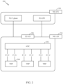
- FIG. 2 illustrates an example logical architecture of a distributed radio access network (RAN) 200, which may be implemented in the wireless communication system illustrated in FIG. 1 .
- a 5G access node 206 may include an access node controller (ANC) 202.
- the ANC may be a central unit (CU) of the distributed RAN 200.
- the backhaul interface to the next generation core network (NG-CN) 204 may terminate at the ANC.
- the backhaul interface to neighboring next generation access nodes (NG-ANs) may terminate at the ANC.
- the ANC may include one or more TRPs 208 (which may also be referred to as BSs, NR BSs, Node Bs, 5G NBs, APs, or some other term). As described above, a TRP may be used interchangeably with "cell.”
- the TRPs 208 may be a DU.
- the TRPs may be connected to one ANC (ANC 202) or more than one ANC (not illustrated).
- ANC ANC
- RaaS radio as a service
- a TRP may include one or more antenna ports.
- the TRPs may be configured to individually (e.g., dynamic selection) or jointly (e.g., joint transmission) serve traffic to a UE.
- the local architecture 200 may be used to illustrate fronthaul definition.
- the architecture may be defined that support fronthauling solutions across different deployment types.
- the architecture may be based on transmit network capabilities (e.g., bandwidth, latency, and/or jitter).
- the architecture may share features and/or components with LTE.
- the next generation AN (NG-AN) 210 may support dual connectivity with NR.
- the NG-AN may share a common fronthaul for LTE and NR.
- the architecture may enable cooperation between and among TRPs 208. For example, cooperation may be preset within a TRP and/or across TRPs via the ANC 202. According to aspects, no inter-TRP interface may be needed or present.
- a dynamic configuration of split logical functions may be present within the architecture 200.
- the Radio Resource Control (RRC) layer, Packet Data Convergence Protocol (PDCP) layer, Radio Link Control (RLC) layer, Medium Access Control (MAC) layer, and a Physical (PHY) layers may be adaptably placed at the DU or CU (e.g., TRP or ANC, respectively).
- a BS may include a central unit (CU) (e.g., ANC 202) and/or one or more distributed units (e.g., one or more TRPs 208).
- CU central unit
- distributed units e.g., one or more TRPs 208.
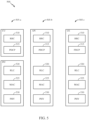
- a centralized RAN unit (C-RU) 304 may host one or more ANC functions.
- the C-RU may host core network functions locally.
- the C-RU may have distributed deployment.
- the C-RU may be closer to the network edge.
- a DU 306 may host one or more TRPs (edge node (EN), an edge unit (EU), a radio head (RH), a smart radio head (SRH), or the like).
- the DU may be located at edges of the network with radio frequency (RF) functionality.
- RF radio frequency
- FIG. 4 illustrates example components of the BS 110 and UE 120 illustrated in FIG. 1 , which may be used to implement aspects of the present disclosure.
- the BS may include a TRP.
- One or more components of the BS 110 and UE 120 may be used to practice aspects of the present disclosure.
- antennas 452, modulator/demodulators 454, TX MIMO processor 466, receive processor 458, transmit processor 464, and/or controller/processor 480 of the UE 120 and/or antennas 434, modulator/demodulators 432, TX MIMO processor 430, transmit processor 420, receive processor 438, and/or controller/processor 440 of the BS 110 may be used to perform the operations described herein and illustrated with reference to FIGs. 15-16 .
- the base station 110 may be the macro BS 110c in FIG. 1 , and the UE 120 may be the UE 120y.
- the base station 110 may also be a base station of some other type.
- the base station 110 may be equipped with antennas 434a through 434t, and the UE 120 may be equipped with antennas 452a through 452r.
- a transmit processor 420 may receive data from a data source 412 and control information from a controller/processor 440.
- the control information may be for the Physical Broadcast Channel (PBCH), Physical Control Format Indicator Channel (PCFICH), Physical Hybrid ARQ Indicator Channel (PHICH), Physical Downlink Control Channel (PDCCH), etc.
- the data may be for the Physical Downlink Shared Channel (PDSCH), etc.
- the processor 420 may process (e.g., encode and symbol map) the data and control information to obtain data symbols and control symbols, respectively.
- the processor 420 may also generate reference symbols, e.g., for the PSS, SSS, and cell-specific reference signal.
- a transmit (TX) multiple-input multiple-output (MIMO) processor 430 may perform spatial processing (e.g., precoding) on the data symbols, the control symbols, and/or the reference symbols, if applicable, and may provide output symbol streams to the modulators (MODs) 432a through 432t.
- Each modulator 432 may process a respective output symbol stream (e.g., for OFDM, etc.) to obtain an output sample stream.
- Each modulator 432 may further process (e.g., convert to analog, amplify, filter, and upconvert) the output sample stream to obtain a downlink signal.
- Downlink signals from modulators 432a through 432t may be transmitted via the antennas 434a through 434t, respectively.
- the antennas 452a through 452r may receive the downlink signals from the base station 110 and may provide received signals to the demodulators (DEMODs) 454a through 454r, respectively.
- Each demodulator 454 may condition (e.g., filter, amplify, downconvert, and digitize) a respective received signal to obtain input samples.
- Each demodulator 454 may further process the input samples (e.g., for OFDM, etc.) to obtain received symbols.
- a MIMO detector 456 may obtain received symbols from all the demodulators 454a through 454r, perform MIMO detection on the received symbols if applicable, and provide detected symbols.
- a receive processor 458 may process (e.g., demodulate, deinterleave, and decode) the detected symbols, provide decoded data for the UE 120 to a data sink 460, and provide decoded control information to a controller/processor 480.
- a transmit processor 464 may receive and process data (e.g., for the Physical Uplink Shared Channel (PUSCH)) from a data source 462 and control information (e.g., for the Physical Uplink Control Channel (PUCCH) from the controller/processor 480.
- the transmit processor 464 may also generate reference symbols for a reference signal.
- the symbols from the transmit processor 464 may be precoded by a TX MIMO processor 466 if applicable, further processed by the demodulators 454a through 454r (e.g., for SC-FDM, etc.), and transmitted to the base station 110.
- the controllers/processors 440 and 480 may direct the operation at the base station 110 and the UE 120, respectively.
- the processor 440 and/or other processors and modules at the base station 110 may perform or direct, e.g., the execution of the functional blocks illustrated in FIG. 6 , and/or other processes for the techniques described herein.
- the processor 480 and/or other processors and modules at the UE 120 may also perform or direct, e.g., the execution of the functional blocks illustrated in FIG. 7 , and/or other processes for the techniques described herein.
- the memories 442 and 482 may store data and program codes for the BS 110 and the UE 120, respectively.
- a scheduler 444 may schedule UEs for data transmission on the downlink and/or uplink.
- a first option 505-a shows a split implementation of a protocol stack, in which implementation of the protocol stack is split between a centralized network access device (e.g., an ANC 202 in FIG. 2 ) and distributed network access device (e.g., DU 208 in FIG. 2 ).
- a centralized network access device e.g., an ANC 202 in FIG. 2
- distributed network access device e.g., DU 208 in FIG. 2
- an RRC layer 510 and a PDCP layer 515 may be implemented by the central unit
- an RLC layer 520, a MAC layer 525, and a PHY layer 530 may be implemented by the DU.
- the CU and the DU may be collocated or non-collocated.
- the first option 505-a may be useful in a macro cell, micro cell, or pico cell deployment.
- a second option 505-b shows a unified implementation of a protocol stack, in which the protocol stack is implemented in a single network access device (e.g., access node (AN), new radio base station (NR BS), a new radio Node-B (NR NB), a network node (NN), or the like.).
- a single network access device e.g., access node (AN), new radio base station (NR BS), a new radio Node-B (NR NB), a network node (NN), or the like.
- the RRC layer 5-10, the PDCP layer 515, the RLC layer 520, the MAC layer 525, and the PHY layer 530 may each be implemented by the AN.
- the second option 505-b may be useful in a femto cell deployment.
- a UE may implement an entire protocol stack 505-c (e.g., the RRC layer 510, the PDCP layer 515, the RLC layer 520, the MAC layer 525, and the PHY layer 530).
- an entire protocol stack 505-c e.g., the RRC layer 510, the PDCP layer 515, the RLC layer 520, the MAC layer 525, and the PHY layer 530.
- FIG. 6 is a schematic diagram 600 that illustrates various components that may be utilized in a wireless communications device 602 that may be employed within the wireless communication system from FIG. 1 .
- the wireless communications device 602 is an example of a device that may be configured to implement the various methods described herein.
- the wireless communications device 602 may be BS 110 from FIG. 1 or any of user equipments 120.
- the wireless communications device 602 may include a processor 604 which controls operation of the wireless communications device 602.
- the processor 604 may also be referred to as a central processing unit (CPU).
- Memory 606 which may include both read-only memory (ROM) and random access memory (RAM), provides instructions and data to the processor 604.
- a portion of the memory 606 may also include non-volatile random access memory (NVRAM).
- the processor 604 typically performs logical and arithmetic operations based on program instructions stored within the memory 606.
- the instructions in the memory 606 may be executable to implement the methods described herein.
- the wireless communications device 602 may also include a housing 608 that may include a transmitter 610 and a receiver 612 to allow transmission and reception of data between the wireless device 602 and a remote location.
- the transmitter 610 and receiver 612 may be combined into a transceiver 614.
- a single or a plurality of transmit antennas 616 may be attached to the housing 608 and electrically coupled to the transceiver 614.
- the wireless communications device 602 may also include (not shown) multiple transmitters, multiple receivers, and multiple transceivers.
- the wireless communications device 602 may also include a signal detector 618 that may be used in an effort to detect and quantify the level of signals received by the transceiver 614.
- the signal detector 618 may detect such signals as total energy, energy per subcarrier per symbol, power spectral density and other signals.
- the wireless communications device 602 may also include a digital signal processor (DSP) 620 for use in processing signals.
- DSP digital signal processor
- the wireless communications device 602 may also include an encoder 622 for use in encoding signals for transmission.
- the encoder may also store the encoded signals in a circular buffer (not shown) and perform rate matching on the encoded signals (e.g., by implementing operations 1700, shown in FIG. 17 ).
- the wireless communication device 602 may include a decoder 624 for use in decoding received signals.
- the various components of the wireless communications device 602 may be coupled together by a bus system 626, which may include a power bus, a control signal bus, and a status signal bus in addition to a data bus.
- the processor 604 may be configured to access instructions stored in the memory 606 to perform connectionless access, in accordance with aspects of the present disclosure discussed below.
- the encoded bitstream 708 may then be stored in circular buffer and rate-matching may be performed on the stored encoded bitstream, for example, according to aspects of the present disclosure described in more detail below. After the encoded bitstream 708 is rate-matched, the encoded bitstream 708 may then be provided to a mapper 710 that generates a sequence of TX symbols 712 that are modulated, amplified and otherwise processed by TX chain 714 to produce an RF signal 716 for transmission through one or more antennas 718.
- a mapper 710 that generates a sequence of TX symbols 712 that are modulated, amplified and otherwise processed by TX chain 714 to produce an RF signal 716 for transmission through one or more antennas 718.
- FIG. 8 is a simplified block diagram illustrating a portion 800 of a wireless device, in accordance with certain aspects of the present disclosure.
- the portion includes an RF modem 810 that may be configured to receive and decode a wirelessly transmitted signal including an encoded message (e.g., a message encoded using a polar code as described below).
- the modem 810 receiving the signal may reside at a user equipment, at a base station, or at any other suitable apparatus or means for carrying out the described functions.
- One or more antennas 802 provides an RF signal 716 (i.e., the RF signal produced in FIG. 7 ) to an access terminal (e.g., UE 120).
- An RX chain 806 processes and demodulates the RF signal 716 and may provide a sequence of symbols 808 to a demapper 812, which produces a bitstream 814 representative of the encoded message.
- a decoder 816 may then be used to decode m-bit information strings from a bitstream that has been encoded using a coding scheme (e.g., a Polar code).
- the decoder 816 may comprise a Viterbi decoder, an algebraic decoder, a butterfly decoder, or another suitable decoder.
- a Viterbi decoder employs the well-known Viterbi algorithm to find the most likely sequence of signaling states (the Viterbi path) that corresponds to a received bitstream 814.
- the bitstream 814 may be decoded based on a statistical analysis of LLRs calculated for the bitstream 814.
- a Viterbi decoder may compare and select the correct Viterbi path that defines a sequence of signaling states using a likelihood ratio test to generate LLRs from the bitstream 814.
- Likelihood ratios can be used to statistically compare the fit of a plurality of candidate Viterbi paths using a likelihood ratio test that compares the logarithm of a likelihood ratio for each candidate Viterbi path (i.e. the LLR) to determine which path is more likely to account for the sequence of symbols that produced the bitstream 814.
- the decoder 816 may then decode the bitstream 814 based on the LLRs to determine the message 818 containing data and/or encoded voice or other content transmitted from the base station (e.g., BS 110).
- FIG. 9 is a diagram 900 showing an example of a DL-centric subframe, which may be used by one or more devices (e.g., BS 110 and/or UE 120) to communicate in the wireless network 100.
- the DL-centric subframe may include a control portion 902.
- the control portion 902 may exist in the initial or beginning portion of the DL-centric subframe.
- the control portion 902 may include various scheduling information and/or control information corresponding to various portions of the DL-centric subframe.
- the control portion 902 may be a physical DL control channel (PDCCH), as indicated in FIG. 9 .
- the DL-centric subframe may also include a DL data portion 904.
- the DL data portion 904 may sometimes be referred to as the payload of the DL-centric subframe.
- the DL data portion 904 may include the communication resources utilized to communicate DL data from the scheduling entity (e.g., UE or BS) to the subordinate entity (e.g., UE).
- the DL data portion 904 may be a physical DL shared channel (PDSCH).
- PDSCH physical DL shared channel
- the DL-centric subframe may also include a common UL portion 906.
- the common UL portion 906 may sometimes be referred to as an UL burst, a common UL burst, and/or various other suitable terms.
- the common UL portion 906 may include feedback information corresponding to various other portions of the DL-centric subframe.
- the common UL portion 906 may include feedback information corresponding to the control portion 902.
- Non-limiting examples of feedback information may include an ACK signal, a NACK signal, a HARQ indicator, and/or various other suitable types of information.
- the common UL portion 906 may include additional or alternative information, such as information pertaining to random access channel (RACH) procedures, scheduling requests (SRs), and various other suitable types of information.
- RACH random access channel
- SRs scheduling requests
- the end of the DL data portion 904 may be separated in time from the beginning of the common UL portion 906.
- This time separation may sometimes be referred to as a gap, a guard period, a guard interval, and/or various other suitable terms.
- This separation provides time for the switch-over from DL communication (e.g., reception operation by the subordinate entity (e.g., UE)) to UL communication (e.g., transmission by the subordinate entity (e.g., UE)).
- DL communication e.g., reception operation by the subordinate entity (e.g., UE)
- UL communication e.g., transmission by the subordinate entity (e.g., UE)
- FIG. 10 is a diagram 1000 showing an example of an UL-centric subframe, which may be used by one or more devices (e.g., BS 110 and/or UE 120) to communicate in the wireless network 100.
- the UL-centric subframe may include a control portion 1002.
- the control portion 1002 may exist in the initial or beginning portion of the UL-centric subframe.
- the control portion 1002 in FIG. 10 may be similar to the control portion described above with reference to FIG. 9 .
- the UL-centric subframe may also include an UL data portion 1004.
- the UL data portion 1004 may sometimes be referred to as the payload of the UL-centric subframe.
- the UL portion may refer to the communication resources utilized to communicate UL data from the subordinate entity (e.g., UE) to the scheduling entity (e.g., UE or BS).
- the control portion 1002 may be a physical DL control channel (PDCCH).
- the end of the control portion 1002 may be separated in time from the beginning of the UL data portion 1004. This time separation may sometimes be referred to as a gap, guard period, guard interval, and/or various other suitable terms. This separation provides time for the switch-over from DL communication (e.g., reception operation by the scheduling entity) to UL communication (e.g., transmission by the scheduling entity).
- the UL-centric subframe may also include a common UL portion 1006.
- the common UL portion 1006 in FIG. 10 may be similar to the common UL portion 1006 described above with reference to FIG. 10 .
- the common UL portion 1006 may additional or alternative include information pertaining to channel quality indicator (CQI), sounding reference signals (SRSs), and various other suitable types of information.
- CQI channel quality indicator
- SRSs sounding reference signals
- One of ordinary skill in the art will understand that the foregoing is merely one example of an UL-centric subframe and alternative structures having similar features may exist without necessarily deviating from the aspects described herein.
- two or more subordinate entities may communicate with each other using sidelink signals.
- Real-world applications of such sidelink communications may include public safety, proximity services, UE-to-network relaying, vehicle-to-vehicle (V2V) communications, Internet of Everything (IoE) communications, IoT communications, mission-critical mesh, and/or various other suitable applications.
- a sidelink signal may refer to a signal communicated from one subordinate entity (e.g., UE1) to another subordinate entity (e.g., UE2) without relaying that communication through the scheduling entity (e.g., UE or BS), even though the scheduling entity may be utilized for scheduling and/or control purposes.
- the sidelink signals may be communicated using a licensed spectrum (unlike wireless local area networks, which typically use an unlicensed spectrum).
- a UE may operate in various radio resource configurations, including a configuration associated with transmitting pilots using a dedicated set of resources (e.g., a radio resource control (RRC) dedicated state, etc.) or a configuration associated with transmitting pilots using a common set of resources (e.g., an RRC common state, etc.).
- RRC radio resource control
- the UE may select a dedicated set of resources for transmitting a pilot signal to a network.
- the UE may select a common set of resources for transmitting a pilot signal to the network.
- a pilot signal transmitted by the UE may be received by one or more network access devices, such as an AN, or a DU, or portions thereof.
- Each receiving network access device may be configured to receive and measure pilot signals transmitted on the common set of resources, and also receive and measure pilot signals transmitted on dedicated sets of resources allocated to the UEs for which the network access device is a member of a monitoring set of network access devices for the UE.
- One or more of the receiving network access devices, or a CU to which receiving network access device(s) transmit the measurements of the pilot signals may use the measurements to identify serving cells for the UEs, or to initiate a change of serving cell for one or more of the UEs.
- Polar codes may be used to encode a stream of bits for transmission.
- Polar codes are the first provably capacity-achieving coding scheme with almost linear (in block length) encoding and decoding complexity.
- Polar codes are widely considered as a candidate for error-correction in the next-generation wireless systems.
- Polar codes have many desirable properties, such as deterministic construction (e.g., based on a fast Hadamard transform), very low and predictable error floors, and simple successive-cancellation (SC) based decoding.
- a number of input bits e.g., information bits
- every estimated bit, û i has a predetermined error probability given that bits u 0 i-1 were correctly decoded, that tends towards either 0 or 0.5. Moreover, the proportion of estimated bits with a low error probability tends towards the capacity of the underlying channel.
- Polar codes exploit a phenomenon called channel polarization by using the most reliable K bits to transmit information, while setting, or freezing, the remaining (N-K) bits to a predetermined value, such as 0, as explained below.
- polar codes transform the channel into N parallel "virtual" channels for the N information bits. If C is a proportion representing the capacity of the channel, then there are almost N*C channels which are completely noise free and there are N*(1 - C) channels which are completely noisy.
- the basic polar coding scheme then involves freezing (i.e., not transmitting) the information bits to be sent along the completely noisy channel and sending information only along the perfect channels. For small-to-medium N, this polarization may not be complete in the sense that there could be several channels which are neither completely useless nor completely noise-free (i.e., channels that are in transition). Depending on the rate of transmission, these channels in transition are either frozen or are used for transmission.
- information allocation i.e., allocation of information or data bits to portions of a codeword
- block rate matching may be performed.
- a sequence designed for a mother code-size, N 2 ⁇ m, is still used, but bits of the codeword corresponding to punctured or shortened bits are not selected as information bits.
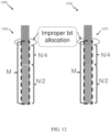
- information bit allocation may be adjusted as shown in FIG. 11 :
- FIG. 11 illustrates an information allocation adjustment (IAA) scheme 1100, according to previously known techniques.
- the number of information bits 1102 allocated to an upper part 1114 and a lower part 1112 of a code 1120 may be further adjusted according to the following algorithms.
- a generator algorithm may then be used to generate the codeword.
- the above described procedure can operate recursively (i.e., adjust information bit allocation in multiple iterations), but this recursive operation may be costly in terms of complexity of the scheme and hence, complexity of a transmitting device configured to perform the procedure recursively.
- One stage bit allocation (1-stage IAA) is typically preferred in practice, but may face large performance losses, especially when codewords are received using successive cancellation (SC) decoding.
- SC successive cancellation
- information bits are adjusted only once, that is, the procedure in 1-stage IAA is to derive K, K + over the upper and lower N/2 bits, respectively, based on K information bits and M coded bits.
- adjustment of M in block puncturing and/or shortening calculations may mitigate and/or resolve the above described issue. Adjustment of M, as described herein, may allow a transmitter to avoid selecting the heavily-punctured subblocks for information bits, thus removing or reducing the effects of worse bit allocation using previously known techniques.
- FIG. 13 is a graph 1300 illustrating successive cancellation (SC) decoding performance of block punctured codes by comparing signal to noise ratios (SNR) at block error rates (BLER) of 0.01 with various numbers of information bits (K) encoded in polar codes.
- the curve 1302 shows the performance of SC decoding of a transmission using a theoretical optimal Gaussian averaging (GA) code using a coding rate of 0.2
- the curve 1304 shows the performance of SC decoding of a transmission using 1-stage IAA and a polarization weighted (PW) sequence for code construction using a coding rate of 0.2.
- Spikes at 1306 and 1308 illustrate degradations of the performance of the 1-stage IAA PW code versus the theoretical optimal code.
- FIG. 14 is a flow diagram of an algorithm 1400 for determining M adj for in block puncturing code construction with 1-stage IAA, according to the invention.
- the algorithm may be used to iteratively calculate M adj , and has 2 rules for ending the iteration (i.e., 2 stopping rules) and determining the final value of M adj to be used in 1-stage IAA.
- the algorithm uses two additional parameters, ⁇ and ⁇ , as well as temporary parameters M ' and N'.
- a processor performing the algorithm begins at block 1402 with setting M adj to zero and setting two temporary parameters, M ' and N' , to initial values of M and N , respectively.
- the processor performing the algorithm determines if M ' is less than half of N ' ( N '/2), and if M ' is less than half of N', then the processor sets a new N' equal to the previous N' /2 , as shown at 1406, and proceeds to return to block 1404.
- the processor continues setting new values for N ' (i.e., equal to the previous value of N' /2) until M' is no longer less than N' /2 , and then proceeds to block 1410.
- the processor performing the algorithm determines if M adj is greater than ⁇ M , and if M adj is greater than ⁇ M , the processor proceeds to block 1412, sets a new M adj equal to the previous M adj + N' /2, and ceases executing the algorithm, i.e., reaches the end at 1450.
- one of the two rules for ending the iterating process is to end iteration when M adj is greater than ⁇ M. If the processor performing the algorithm determines that M adj is not greater than ⁇ M , then the processor proceeds to block 1420.
- the processor determines if M' is less than (1 + ⁇ ) x N' / 2, and, if M ' is less than (1 + ⁇ ) x N' /2, the processor ceases executing the algorithm, i.e., reaches the end at 1450. Thus, another of the two rules for ending the iterating process is to end iteration when M ' is less than (1 + ⁇ ) x N '/2. If the processor determines that M ' is not less than (1 + ⁇ ) x N'/2, then the processor proceeds to block 1430.
- the processor sets a new M adj equal to the previous M adj + N' / 2, sets a new M ' equal to the previous M' - N' / 2, sets a new N' equal to the previous N' /2 , and returns to block 1404.
- the processor reaches the end at 1450, the last calculated M adj is the value to be used for the 1-stage IAA.
- the iterating process is ended when M adj . is greater than ⁇ M .
- FIG. 16 is a graph 1600 illustrating successive cancellation (SC) decoding performance of block punctured codes by comparing signal to noise ratios (SNR) at block error rates (BLER) of 0.01 with various numbers of information bits (K) encoded in polar codes.
- the curve 1602 shows the performance of SC decoding of a transmission using a theoretical optimal Gaussian averaging (GA) code using a coding rate of 0.2
- the curve 1604 shows the performance of SC decoding of a transmission using 1-stage IAA and a polarization weighted (PW) sequence for code construction using a coding rate of 0.2
- the curve 1606 shows the performance of SC decoding of a transmission using 1-stage IAA with an adjustment to M, according to aspects of the present disclosure.
- the curve 1662 shows the performance of SC decoding of a transmission using a theoretical optimal Gaussian averaging (GA) code using a coding rate of 0.6
- the curve 1664 shows the performance of SC decoding of a transmission using 1-stage IAA and a polarization weighted (PW) sequence for code construction using a coding rate of 0.6
- the curve 1666 shows the performance of SC decoding of a transmission using 1-stage IAA with an adjustment to M, according to aspects of the present disclosure.
- the spikes at 1668 and at other locations illustrate degradations of the performance of the 1-stage IAA PW code versus the theoretical optimal code.
- curves at 1612, 1622, and 1632 show the performances using coding rates of 0.3, 0.4, and 0.5.
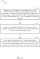
- FIG. 17 illustrates example operations 1700 for wireless communications, according to aspects of the present disclosure. Operations 1700 may be performed by a wireless communications device, such as base station 110 (shown in FIG. 1 ), user equipment 120 (also shown in FIG. 1 ), and/or wireless communications device 602 (shown in FIG. 6 ).
- a wireless communications device such as base station 110 (shown in FIG. 1 ), user equipment 120 (also shown in FIG. 1 ), and/or wireless communications device 602 (shown in FIG. 6 ).
- Operations 1700 begin at block 1702 with the wireless communications device iteratively determining a parameter, M adj , for construction of a polar code of size N for use in encoding K information bits, based on: at least two parameters, ⁇ and ⁇ , related to how many iterations to use in determining M adj , and a number of encoded bits, M.
- M adj a parameter for construction of a polar code of size N for use in encoding K information bits
- ⁇ and ⁇ related to how many iterations to use in determining M adj , and a number of encoded bits, M.
- UE 120 shown in FIG. 1 , iteratively, e.g., as shown above with reference to FIG.
- M adj determines a parameter, M adj , for construction of a polar code of size N for use in encoding K information bits, based on: at least two parameters, ⁇ and ⁇ , related to how many iterations to use in determining M adj , and a number of encoded bits, M.
- operations 1700 continue with the wireless communications device adjusting an information bit allocation of the K information bits to an upper part and a lower part of the polar code based on M adj .
- the UE 120 adjusts an information bit allocation of the K information bits (mentioned in block 1702) to an upper part and a lower part of the polar code based on M adj (i.e., the value of M adj iteratively determined in block 1702).
- Operations 1700 continue at block 1706 with the wireless communications device transmitting a codeword via a wireless medium, wherein the codeword is generated using the polar code and the K information bits according to the allocation.
- the UE 120 transmits a codeword via a wireless medium, wherein the codeword is generated using the polar code and the K information bits (mentioned in block 1702) according to the allocation (i.e., the adjusted information bit allocation from block 1704) to the upper part and the upper part.
- the methods disclosed herein comprise one or more steps or actions for achieving the described method.
- the method steps and/or actions may be interchanged with one another without departing from the scope of the claims.
- the order and/or use of specific steps and/or actions may be modified without departing from the scope of the claims.
- a phrase referring to "at least one of" a list of items refers to any combination of those items, including single members.
- "at least one of: a, b, or c” is intended to cover a, b, c, a-b, a-c, b-c, and a-b-c, as well as any combination with multiples of the same element (e.g., a-a, a-a-a, a-a-b, a-a-c, a-b-b, a-c-c, b-b, b-b-b, b-b-c, c-c, and c-c-c or any other ordering of a, b, and c).
- determining encompasses a wide variety of actions. For example, “determining” may include calculating, computing, processing, deriving, investigating, looking up (e.g., looking up in a table, a database or another data structure), ascertaining and the like. Also, “determining” may include receiving (e.g., receiving information), accessing (e.g., accessing data in a memory) and the like. Also, “determining” may include resolving, selecting, choosing, establishing and the like.
- a device may have an interface to output a frame for transmission.
- a processor may output a frame, via a bus interface, to an RF front end for transmission.
- a device may have an interface to obtain a frame received from another device.
- a processor may obtain (or receive) a frame, via a bus interface, from an RF front end for transmission.
- the various operations of methods described above may be performed by any suitable means capable of performing the corresponding functions.
- the means may include various hardware and/or software component(s) and/or module(s), including, but not limited to a circuit, an application specific integrated circuit (ASIC), or processor.
- ASIC application specific integrated circuit
- means for transmitting, means for receiving, means for determining, means for performing (e.g., rate-matching), means for encoding, means for, puncturing, means for repeating, means for shortening, and/or means for generating may comprise one or more processors or antennas at the BS 110 or UE 120, such as the transmit processor 220, controller/processor 240, receive processor 238, or antennas 234 at the BS 110 and/or the transmit processor 264, controller/processor 280, receive processor 258, or antennas 252 at the UE 120.
- DSP digital signal processor
- ASIC application specific integrated circuit
- FPGA field programmable gate array
- PLD programmable logic device
- a general-purpose processor may be a microprocessor, but in the alternative, the processor may be any commercially available processor, controller, microcontroller, or state machine.
- a processor may also be implemented as a combination of computing devices, e.g., a combination of a DSP and a microprocessor, a plurality of microprocessors, one or more microprocessors in conjunction with a DSP core, or any other such configuration.
- an example hardware configuration may comprise a processing system in a wireless node.
- the processing system may be implemented with a bus architecture.
- the bus may include any number of interconnecting buses and bridges depending on the specific application of the processing system and the overall design constraints.
- the bus may link together various circuits including a processor, machine-readable media, and a bus interface.
- the bus interface may be used to connect a network adapter, among other things, to the processing system via the bus.
- the network adapter may be used to implement the signal processing functions of the PHY layer.
- a user interface e.g., keypad, display, mouse, joystick, etc.
- the functions may be stored or transmitted over as one or more instructions or code on a computer-readable medium.
- Software shall be construed broadly to mean instructions, data, or any combination thereof, whether referred to as software, firmware, middleware, microcode, hardware description language, or otherwise.
- Computer-readable media include both computer storage media and communication media including any medium that facilitates transfer of a computer program from one place to another.
- the processor may be responsible for managing the bus and general processing, including the execution of software modules stored on the machine-readable storage media.
- a computer-readable storage medium may be coupled to a processor such that the processor can read information from, and write information to, the storage medium. In the alternative, the storage medium may be integral to the processor.
- the machine-readable media may include a transmission line, a carrier wave modulated by data, and/or a computer readable storage medium with instructions stored thereon separate from the wireless node, all of which may be accessed by the processor through the bus interface.
- the machine-readable media, or any portion thereof may be integrated into the processor, such as the case may be with cache and/or general register files.
- machine-readable storage media may include, by way of example, RAM (Random Access Memory), flash memory, ROM (Read Only Memory), PROM (Programmable Read-Only Memory), EPROM (Erasable Programmable Read-Only Memory), EEPROM (Electrically Erasable Programmable Read-Only Memory), registers, magnetic disks, optical disks, hard drives, or any other suitable storage medium, or any combination thereof.
- RAM Random Access Memory
- ROM Read Only Memory
- PROM PROM
- EPROM Erasable Programmable Read-Only Memory
- EEPROM Electrical Erasable Programmable Read-Only Memory
- registers magnetic disks, optical disks, hard drives, or any other suitable storage medium, or any combination thereof.
- the machine-readable media may be embodied in a computer-program product.
- any connection is properly termed a computer-readable medium.
- the software is transmitted from a website, server, or other remote source using a coaxial cable, fiber optic cable, twisted pair, digital subscriber line (DSL), or wireless technologies such as infrared (IR), radio, and microwave
- the coaxial cable, fiber optic cable, twisted pair, DSL, or wireless technologies such as infrared, radio, and microwave are included in the definition of medium.
- Disk and disc include compact disc (CD), laser disc, optical disc, digital versatile disc (DVD), floppy disk, and Blu-ray ® disc where disks usually reproduce data magnetically, while discs reproduce data optically with lasers.
- computer-readable media may comprise non-transitory computer-readable media (e.g., tangible media).
- computer-readable media may comprise transitory computer-readable media (e.g., a signal). Combinations of the above should also be included within the scope of computer-readable media.
- modules and/or other appropriate means for performing the methods and techniques described herein can be downloaded and/or otherwise obtained by a user terminal and/or base station as applicable.
- a user terminal and/or base station can be coupled to a server to facilitate the transfer of means for performing the methods described herein.
- various methods described herein can be provided via storage means (e.g., RAM, ROM, a physical storage medium such as a compact disc (CD) or floppy disk, etc.), such that a user terminal and/or base station can obtain the various methods upon coupling or providing the storage means to the device.
- storage means e.g., RAM, ROM, a physical storage medium such as a compact disc (CD) or floppy disk, etc.
- CD compact disc
- floppy disk etc.
- any other suitable technique for providing the methods and techniques described herein to a device can be utilized.
Landscapes
- Engineering & Computer Science (AREA)
- Computer Networks & Wireless Communication (AREA)
- Signal Processing (AREA)
- Physics & Mathematics (AREA)
- Probability & Statistics with Applications (AREA)
- Theoretical Computer Science (AREA)
- Mobile Radio Communication Systems (AREA)
Claims (7)
- Ein Verfahren (1700) für drahtlose Kommunikationen, das umfasst:
iteratives Bestimmen (1702) eines Parameters, Madj, zum Aufbau eines Polarcodes der Größe N zur Verwendung bei einer Codierung von K Informationsbits, basierend auf:zumindest zwei Parametern, α und β, die sich darauf beziehen, wie viele Iterationen bei der Bestimmung von Madj verwendet werden sollen, undeiner Anzahl codierter Bits, M;wobei das iterative Bestimmen von Madj ein Ausführen eines Algorithmus umfasst, der umfasst:Setzen von M'=M;Setzen von N'=N;Setzen von Madj=0;Bestimmen (1404), ob M' kleiner als N'/2 ist;wenn M' kleiner als N'/2 ist, Setzen (1406) eines neuen N' gleich des vorherigen N'/2 auf iterative oder rekursive Weise, bis M' größer oder gleich des neuen N'/2 ist;wenn M' größer oder gleich N'/2 ist:Bestimmen (1410), ob Madj größer ist als αM;wenn Madj größer als αM ist:Setzen (1412) eines neuen Madj gleich dem vorherigen Madj + N'/2 undBeenden (1450) der Ausführung des Algorithmus;wenn Madj kleiner oder gleich αM ist:Bestimmen (1420), ob M' kleiner als (1+β) * (N'/2) ist;wenn M' kleiner als (1+β) * (N'/2) ist:Beenden (1450) der Ausführung des Algorithmus; undwenn M' größer oder gleich (1+β) * (N'/2) ist:Setzen (1430) eines neuen Madj gleich dem vorherigen Madj+N'/2,Setzen (1430) eines neuen M' gleich dem vorherigen M'-N'/2,Setzen (1430) eines neuen N' gleich dem vorherigen N'/2, undFortsetzen des Algorithmus ab dem Schritt des Bestimmens (1404), ob M' kleiner als N'/2 ist,Anpassen (1704) einer Informationsbitzuordnung der K Informationsbits zu einem oberen Teil und einem unteren Teil des Polarcodes basierend auf Madj anstelle M, und Erzeugen eines Codeworts unter Verwendung des Polarcodes und der K Informationsbits gemäß der angepassten Informationsbitzuordnung, wobei das erzeugte Codewort aus den M codierten Bits besteht, die durch Blockpunktierung oder Blockverkürzung erhalten werden, wobei die Informationsbitzuordnung eine einstufige Bitzuordnung ist; undÜbertragen (1706) des erzeugten Codeworts über ein drahtloses Medium. - Das Verfahren gemäß Anspruch 1, das weiter umfasst:Empfangen einer Angabe eines Werts von α in einer Konfiguration; undEmpfangen einer Angabe eines Werts von β in der Konfiguration oder einer anderen Konfiguration.
- Das Verfahren gemäß Anspruch 1, wobei α gleich der Summe von 2-i von i=1 bis zu der Anzahl von Iterationen ist.
- Eine Vorrichtung (600) für drahtlose Kommunikationen, die umfasst:
Mittel, das ausgebildet ist zum iterativen Bestimmen eines Parameters Madj zum Aufbau eines Polarcodes der Größe N zur Verwendung bei einer Codierung von K Informationsbits, basierend auf:zumindest zwei Parametern, α und β, die sich darauf beziehen, wie viele Iterationen bei der Bestimmung von Madj verwendet werden sollen, undeiner Anzahl codierter Bits, M;wobei das Mittel zum iterativen Bestimmen von Madj ein Mittel umfasst zum Ausführen eines Algorithmus, der umfasst:Setzen von M'=M;Setzen von N'=N;Setzen von Madj=0;Bestimmen, ob M' kleiner als N'/2 ist;wenn M' kleiner als N'/2 ist, Setzen eines neuen N' gleich des vorherigen N'/2 auf iterative oder rekursive Weise, bis M' größer oder gleich des neuen N'/2 ist;wenn M' größer oder gleich N'/2 ist:Bestimmen, ob Madj größer ist als αM;wenn Madj größer als αM ist:Setzen eines neuen Madj gleich dem vorherigen Madj + N'/2 undBeenden der Ausführung des Algorithmus;wenn Madj kleiner oder gleich αM ist:Bestimmen (1420), ob M' kleiner als (1+β) * (N'/2) ist;wenn M' kleiner als (1+β) * (N'/2) ist:Beenden (1450) der Ausführung des Algorithmus; undwenn M' größer oder gleich (1+β) * (N'/2) ist:Setzen (1430) eines neuen Madj gleich dem vorherigen Madj+N'/2,Setzen (1430) eines neuen M' gleich dem vorherigen M'-N'/2,Setzen (1430) eines neuen N' gleich dem vorherigen N'/2, undFortsetzen des Algorithmus ab dem Schritt des Bestimmens (1404), ob M' kleiner als N'/2 ist,Mittel, das ausgebildet ist zum Anpassen einer Informationsbitzuordnung der K Informationsbits zu einem oberen Teil und einem unteren Teil des Polarcodes basierend auf Madj anstelle M, und Mittel zum Erzeugen eines Codeworts unter Verwendung des Polarcodes und der K Informationsbits gemäß der angepassten Informationsbitzuordnung, wobei das erzeugte Codewort aus den M codierten Bits besteht, die durch Blockpunktierung oder Blockverkürzung erhalten werden, wobei die Informationsbitzuordnung eine einstufige Bitzuordnung ist; undMittel, das ausgebildet ist zum Übertragen eines Codeworts über ein drahtloses Medium. - Die Vorrichtung gemäß Anspruch 4, die weiter umfasst:Mittel, das ausgebildet ist zum Empfangen einer Angabe eines Werts von α in einer Konfiguration; undMittel, das ausgebildet ist zum Empfangen einer Angabe eines Werts von β in der Konfiguration oder einer anderen Konfiguration.
- Die Vorrichtung gemäß Anspruch 4, wobei α gleich der Summe von 2-i von i=1 bis zu der Anzahl von Iterationen ist.
- Computerlesbares Medium (606) für drahtlose Kommunikationen, das Anweisungen umfasst, die bei Ausführung durch einen Prozessor (604) den Prozessor (604) veranlassen, das Verfahren gemäß einem der Ansprüche 1 bis 3 auszuführen.
Applications Claiming Priority (1)
| Application Number | Priority Date | Filing Date | Title |
|---|---|---|---|
| PCT/CN2019/082637 WO2020210936A1 (en) | 2019-04-15 | 2019-04-15 | Adjusting m for polar codes rate matching design |
Publications (3)
| Publication Number | Publication Date |
|---|---|
| EP3957012A1 EP3957012A1 (de) | 2022-02-23 |
| EP3957012A4 EP3957012A4 (de) | 2022-12-28 |
| EP3957012B1 true EP3957012B1 (de) | 2025-06-25 |
Family
ID=72836790
Family Applications (1)
| Application Number | Title | Priority Date | Filing Date |
|---|---|---|---|
| EP19925180.2A Active EP3957012B1 (de) | 2019-04-15 | 2019-04-15 | Anpassung von m für design zur polarcode-raten-angleichung |
Country Status (4)
| Country | Link |
|---|---|
| US (1) | US12057937B2 (de) |
| EP (1) | EP3957012B1 (de) |
| CN (1) | CN113661666B (de) |
| WO (1) | WO2020210936A1 (de) |
Families Citing this family (1)
| Publication number | Priority date | Publication date | Assignee | Title |
|---|---|---|---|---|
| US12237845B2 (en) | 2021-09-28 | 2025-02-25 | Samsung Electronics Co., Ltd. | Devices and methods for constructing polar like codes |
Family Cites Families (6)
| Publication number | Priority date | Publication date | Assignee | Title |
|---|---|---|---|---|
| WO2017196391A1 (en) * | 2016-05-12 | 2017-11-16 | Intel Corporation | Constructing, representing, and encoding polar codes |
| US10728080B2 (en) | 2016-05-20 | 2020-07-28 | Qualcomm Incorporated | Polar codes and modulation mappings |
| EP3273602B1 (de) * | 2016-07-19 | 2022-01-26 | MediaTek Inc. | Ratenanpassung niedriger komplexität für polare codes |
| US10630346B2 (en) | 2016-08-25 | 2020-04-21 | Qualcomm Incorporated | Carrier aggregation under different subframe structures |
| CN107425941B (zh) * | 2017-06-16 | 2022-11-18 | 华为技术有限公司 | 速率匹配和解速率匹配的方法及装置 |
| US10742350B2 (en) * | 2017-06-19 | 2020-08-11 | Samsung Electronics Co., Ltd. | Method and apparatus of rate-matching for communication and broadcasting systems |
-
2019
- 2019-04-15 CN CN201980095217.6A patent/CN113661666B/zh active Active
- 2019-04-15 WO PCT/CN2019/082637 patent/WO2020210936A1/en not_active Ceased
- 2019-04-15 US US17/593,902 patent/US12057937B2/en active Active
- 2019-04-15 EP EP19925180.2A patent/EP3957012B1/de active Active
Also Published As
| Publication number | Publication date |
|---|---|
| CN113661666B (zh) | 2024-04-02 |
| US12057937B2 (en) | 2024-08-06 |
| US20220190957A1 (en) | 2022-06-16 |
| CN113661666A (zh) | 2021-11-16 |
| EP3957012A1 (de) | 2022-02-23 |
| EP3957012A4 (de) | 2022-12-28 |
| WO2020210936A1 (en) | 2020-10-22 |
Similar Documents
| Publication | Publication Date | Title |
|---|---|---|
| CA3046964C (en) | Control channel code rate selection | |
| US11956079B2 (en) | Rate-matching scheme for polar codes | |
| EP3721571B1 (de) | Zeitbasierte redundanzversionsbestimmung für berechtigungsfreie signalisierung | |
| JP7488046B2 (ja) | Polar符号を使用した制御チャネルのためのレートマッチング方式 | |
| EP3738235B1 (de) | Zuteilung codierter bits zur segmentierung von uplink-steuerungsinformationen (uci) | |
| EP3711167B1 (de) | Segmentierung von uplink-steuerungsinformationen für polare codes | |
| WO2019090468A1 (en) | Methods and apparatus for crc concatenated polar encoding | |
| WO2018129734A1 (en) | Dynamic frozen polar codes | |
| EP3714564B1 (de) | Ringpufferbasierte hybride automatische neuübertragungsanforderung für polare codes | |
| EP3665780B1 (de) | Vereinheitlichtes muster zur punktion und verkürzung von polaren codes | |
| EP3957012B1 (de) | Anpassung von m für design zur polarcode-raten-angleichung |
Legal Events
| Date | Code | Title | Description |
|---|---|---|---|
| STAA | Information on the status of an ep patent application or granted ep patent |
Free format text: STATUS: THE INTERNATIONAL PUBLICATION HAS BEEN MADE |
|
| PUAI | Public reference made under article 153(3) epc to a published international application that has entered the european phase |
Free format text: ORIGINAL CODE: 0009012 |
|
| STAA | Information on the status of an ep patent application or granted ep patent |
Free format text: STATUS: REQUEST FOR EXAMINATION WAS MADE |
|
| 17P | Request for examination filed |
Effective date: 20210922 |
|
| AK | Designated contracting states |
Kind code of ref document: A1 Designated state(s): AL AT BE BG CH CY CZ DE DK EE ES FI FR GB GR HR HU IE IS IT LI LT LU LV MC MK MT NL NO PL PT RO RS SE SI SK SM TR |
|
| DAV | Request for validation of the european patent (deleted) | ||
| DAX | Request for extension of the european patent (deleted) | ||
| A4 | Supplementary search report drawn up and despatched |
Effective date: 20221128 |
|
| RIC1 | Information provided on ipc code assigned before grant |
Ipc: H03M 13/00 20060101ALI20221122BHEP Ipc: H03M 13/13 20060101ALI20221122BHEP Ipc: H04L 1/00 20060101AFI20221122BHEP |
|
| STAA | Information on the status of an ep patent application or granted ep patent |
Free format text: STATUS: EXAMINATION IS IN PROGRESS |
|
| 17Q | First examination report despatched |
Effective date: 20231102 |
|
| GRAP | Despatch of communication of intention to grant a patent |
Free format text: ORIGINAL CODE: EPIDOSNIGR1 |
|
| STAA | Information on the status of an ep patent application or granted ep patent |
Free format text: STATUS: GRANT OF PATENT IS INTENDED |
|
| INTG | Intention to grant announced |
Effective date: 20250122 |
|
| RAP3 | Party data changed (applicant data changed or rights of an application transferred) |
Owner name: QUALCOMM INCORPORATED |
|
| GRAS | Grant fee paid |
Free format text: ORIGINAL CODE: EPIDOSNIGR3 |
|
| GRAA | (expected) grant |
Free format text: ORIGINAL CODE: 0009210 |
|
| STAA | Information on the status of an ep patent application or granted ep patent |
Free format text: STATUS: THE PATENT HAS BEEN GRANTED |
|
| AK | Designated contracting states |
Kind code of ref document: B1 Designated state(s): AL AT BE BG CH CY CZ DE DK EE ES FI FR GB GR HR HU IE IS IT LI LT LU LV MC MK MT NL NO PL PT RO RS SE SI SK SM TR |
|
| REG | Reference to a national code |
Ref country code: GB Ref legal event code: FG4D |
|
| REG | Reference to a national code |
Ref country code: CH Ref legal event code: EP |
|
| REG | Reference to a national code |
Ref country code: CH Ref legal event code: EP |
|
| REG | Reference to a national code |
Ref country code: IE Ref legal event code: FG4D |
|
| REG | Reference to a national code |
Ref country code: DE Ref legal event code: R096 Ref document number: 602019071778 Country of ref document: DE |
|
| PG25 | Lapsed in a contracting state [announced via postgrant information from national office to epo] |
Ref country code: FI Free format text: LAPSE BECAUSE OF FAILURE TO SUBMIT A TRANSLATION OF THE DESCRIPTION OR TO PAY THE FEE WITHIN THE PRESCRIBED TIME-LIMIT Effective date: 20250625 |
|
| REG | Reference to a national code |
Ref country code: LT Ref legal event code: MG9D |
|
| PG25 | Lapsed in a contracting state [announced via postgrant information from national office to epo] |
Ref country code: NO Free format text: LAPSE BECAUSE OF FAILURE TO SUBMIT A TRANSLATION OF THE DESCRIPTION OR TO PAY THE FEE WITHIN THE PRESCRIBED TIME-LIMIT Effective date: 20250925 Ref country code: GR Free format text: LAPSE BECAUSE OF FAILURE TO SUBMIT A TRANSLATION OF THE DESCRIPTION OR TO PAY THE FEE WITHIN THE PRESCRIBED TIME-LIMIT Effective date: 20250926 |
|
| PG25 | Lapsed in a contracting state [announced via postgrant information from national office to epo] |
Ref country code: BG Free format text: LAPSE BECAUSE OF FAILURE TO SUBMIT A TRANSLATION OF THE DESCRIPTION OR TO PAY THE FEE WITHIN THE PRESCRIBED TIME-LIMIT Effective date: 20250625 |
|
| PG25 | Lapsed in a contracting state [announced via postgrant information from national office to epo] |
Ref country code: HR Free format text: LAPSE BECAUSE OF FAILURE TO SUBMIT A TRANSLATION OF THE DESCRIPTION OR TO PAY THE FEE WITHIN THE PRESCRIBED TIME-LIMIT Effective date: 20250625 |
|
| PG25 | Lapsed in a contracting state [announced via postgrant information from national office to epo] |
Ref country code: RS Free format text: LAPSE BECAUSE OF FAILURE TO SUBMIT A TRANSLATION OF THE DESCRIPTION OR TO PAY THE FEE WITHIN THE PRESCRIBED TIME-LIMIT Effective date: 20250925 |
|
| PG25 | Lapsed in a contracting state [announced via postgrant information from national office to epo] |
Ref country code: LV Free format text: LAPSE BECAUSE OF FAILURE TO SUBMIT A TRANSLATION OF THE DESCRIPTION OR TO PAY THE FEE WITHIN THE PRESCRIBED TIME-LIMIT Effective date: 20250625 |
|
| REG | Reference to a national code |
Ref country code: NL Ref legal event code: MP Effective date: 20250625 |
|
| PG25 | Lapsed in a contracting state [announced via postgrant information from national office to epo] |
Ref country code: NL Free format text: LAPSE BECAUSE OF FAILURE TO SUBMIT A TRANSLATION OF THE DESCRIPTION OR TO PAY THE FEE WITHIN THE PRESCRIBED TIME-LIMIT Effective date: 20250625 |
|
| PG25 | Lapsed in a contracting state [announced via postgrant information from national office to epo] |
Ref country code: PT Free format text: LAPSE BECAUSE OF FAILURE TO SUBMIT A TRANSLATION OF THE DESCRIPTION OR TO PAY THE FEE WITHIN THE PRESCRIBED TIME-LIMIT Effective date: 20251027 |
|
| REG | Reference to a national code |
Ref country code: AT Ref legal event code: MK05 Ref document number: 1807707 Country of ref document: AT Kind code of ref document: T Effective date: 20250625 |