EP3665542B1 - Dispositif de réglage autorégulé pour une vanne de régulation de fluide, système de thermorégulation et un système de distribution comprenant celui-ci, ainsi que procédé associé - Google Patents
Dispositif de réglage autorégulé pour une vanne de régulation de fluide, système de thermorégulation et un système de distribution comprenant celui-ci, ainsi que procédé associé Download PDFInfo
- Publication number
- EP3665542B1 EP3665542B1 EP18786704.9A EP18786704A EP3665542B1 EP 3665542 B1 EP3665542 B1 EP 3665542B1 EP 18786704 A EP18786704 A EP 18786704A EP 3665542 B1 EP3665542 B1 EP 3665542B1
- Authority
- EP
- European Patent Office
- Prior art keywords
- temperature
- flow
- self
- regulating
- adjustment device
- Prior art date
- Legal status (The legal status is an assumption and is not a legal conclusion. Google has not performed a legal analysis and makes no representation as to the accuracy of the status listed.)
- Active
Links
- 238000000034 method Methods 0.000 title claims description 23
- 230000004913 activation Effects 0.000 claims description 44
- 238000001994 activation Methods 0.000 claims description 44
- 230000009849 deactivation Effects 0.000 claims description 33
- 239000007788 liquid Substances 0.000 claims description 20
- 238000004364 calculation method Methods 0.000 claims description 19
- 238000001514 detection method Methods 0.000 claims description 18
- 230000008859 change Effects 0.000 claims description 5
- 230000003213 activating effect Effects 0.000 claims 1
- 238000010438 heat treatment Methods 0.000 description 82
- 230000006870 function Effects 0.000 description 35
- 238000012546 transfer Methods 0.000 description 18
- 238000009434 installation Methods 0.000 description 9
- 230000008901 benefit Effects 0.000 description 6
- 230000001105 regulatory effect Effects 0.000 description 6
- 230000006399 behavior Effects 0.000 description 5
- 238000001816 cooling Methods 0.000 description 5
- 230000006978 adaptation Effects 0.000 description 3
- 238000004891 communication Methods 0.000 description 3
- 238000013461 design Methods 0.000 description 3
- 230000008569 process Effects 0.000 description 3
- 230000001960 triggered effect Effects 0.000 description 3
- 238000004378 air conditioning Methods 0.000 description 2
- 238000009529 body temperature measurement Methods 0.000 description 2
- 238000011161 development Methods 0.000 description 2
- 230000018109 developmental process Effects 0.000 description 2
- 238000010586 diagram Methods 0.000 description 2
- 239000012530 fluid Substances 0.000 description 2
- 238000005057 refrigeration Methods 0.000 description 2
- 230000009471 action Effects 0.000 description 1
- 230000003044 adaptive effect Effects 0.000 description 1
- 238000013459 approach Methods 0.000 description 1
- 230000000052 comparative effect Effects 0.000 description 1
- 230000000295 complement effect Effects 0.000 description 1
- 238000010276 construction Methods 0.000 description 1
- 230000001419 dependent effect Effects 0.000 description 1
- 230000005611 electricity Effects 0.000 description 1
- 238000005265 energy consumption Methods 0.000 description 1
- 238000000605 extraction Methods 0.000 description 1
- 230000007274 generation of a signal involved in cell-cell signaling Effects 0.000 description 1
- 238000009413 insulation Methods 0.000 description 1
- 238000012544 monitoring process Methods 0.000 description 1
- 238000005457 optimization Methods 0.000 description 1
- 238000012545 processing Methods 0.000 description 1
- 230000035484 reaction time Effects 0.000 description 1
- 238000009420 retrofitting Methods 0.000 description 1
- 230000003068 static effect Effects 0.000 description 1
- 238000005496 tempering Methods 0.000 description 1
- XLYOFNOQVPJJNP-UHFFFAOYSA-N water Substances O XLYOFNOQVPJJNP-UHFFFAOYSA-N 0.000 description 1
Images


Classifications
-
- F—MECHANICAL ENGINEERING; LIGHTING; HEATING; WEAPONS; BLASTING
- F24—HEATING; RANGES; VENTILATING
- F24D—DOMESTIC- OR SPACE-HEATING SYSTEMS, e.g. CENTRAL HEATING SYSTEMS; DOMESTIC HOT-WATER SUPPLY SYSTEMS; ELEMENTS OR COMPONENTS THEREFOR
- F24D19/00—Details
- F24D19/10—Arrangement or mounting of control or safety devices
- F24D19/1006—Arrangement or mounting of control or safety devices for water heating systems
- F24D19/1009—Arrangement or mounting of control or safety devices for water heating systems for central heating
- F24D19/1015—Arrangement or mounting of control or safety devices for water heating systems for central heating using a valve or valves
- F24D19/1018—Radiator valves
-
- G—PHYSICS
- G05—CONTROLLING; REGULATING
- G05D—SYSTEMS FOR CONTROLLING OR REGULATING NON-ELECTRIC VARIABLES
- G05D23/00—Control of temperature
- G05D23/19—Control of temperature characterised by the use of electric means
- G05D23/1927—Control of temperature characterised by the use of electric means using a plurality of sensors
- G05D23/193—Control of temperature characterised by the use of electric means using a plurality of sensors sensing the temperaure in different places in thermal relationship with one or more spaces
- G05D23/1932—Control of temperature characterised by the use of electric means using a plurality of sensors sensing the temperaure in different places in thermal relationship with one or more spaces to control the temperature of a plurality of spaces
- G05D23/1934—Control of temperature characterised by the use of electric means using a plurality of sensors sensing the temperaure in different places in thermal relationship with one or more spaces to control the temperature of a plurality of spaces each space being provided with one sensor acting on one or more control means
-
- F—MECHANICAL ENGINEERING; LIGHTING; HEATING; WEAPONS; BLASTING
- F24—HEATING; RANGES; VENTILATING
- F24D—DOMESTIC- OR SPACE-HEATING SYSTEMS, e.g. CENTRAL HEATING SYSTEMS; DOMESTIC HOT-WATER SUPPLY SYSTEMS; ELEMENTS OR COMPONENTS THEREFOR
- F24D19/00—Details
- F24D19/10—Arrangement or mounting of control or safety devices
-
- G—PHYSICS
- G05—CONTROLLING; REGULATING
- G05D—SYSTEMS FOR CONTROLLING OR REGULATING NON-ELECTRIC VARIABLES
- G05D23/00—Control of temperature
- G05D23/19—Control of temperature characterised by the use of electric means
- G05D23/1919—Control of temperature characterised by the use of electric means characterised by the type of controller
- G05D23/1921—Control of temperature characterised by the use of electric means characterised by the type of controller using a thermal motor
-
- F—MECHANICAL ENGINEERING; LIGHTING; HEATING; WEAPONS; BLASTING
- F24—HEATING; RANGES; VENTILATING
- F24D—DOMESTIC- OR SPACE-HEATING SYSTEMS, e.g. CENTRAL HEATING SYSTEMS; DOMESTIC HOT-WATER SUPPLY SYSTEMS; ELEMENTS OR COMPONENTS THEREFOR
- F24D2220/00—Components of central heating installations excluding heat sources
- F24D2220/02—Fluid distribution means
- F24D2220/0257—Thermostatic valves
Definitions
- the present application relates to a setting device for the self-regulating setting of a flow control valve of a consumer loop with a heat exchanger in a temperature control system and a temperature control system with the same, as well as a distributor device for the self-regulating distribution of a liquid heat carrier to several consumer loops.
- the application also relates to a corresponding method for the self-regulating setting of a flow rate in a consumer loop and for self-regulating distribution, which achieves a needs-based compensation of partial flows of a liquid heat transfer medium on several consumer loops.
- a technical background of the invention lies in the use of heating and air conditioning systems for rooms, such as in particular underfloor heating, surface heating or cooling ceilings, which are installed in a building in order to provide a weather-independent, selectable room temperature.
- the WO 2015/142879 A1 a retrofit for a system for heat transfer through a liquid, using a thermostat for regulation.
- the retrofit has a circuit, a flow temperature sensor and a return temperature sensor.
- the thermostat outputs a control signal for the valve.
- the hot and cold setpoints can be modified dynamically. This can be done using a readable table or based on a formula based on the flow temperature.
- a feedback can also be provided, by means of which the circuit achieves an opening degree of the valve. Furthermore, a memory for data relating to a course of temperatures, valve positions, etc. can be provided. The thermostat outputs a control signal for the valve position so that the room thermostat is a component that is specific to the overall system that can be retrofitted and that is required for every room.
- the US 2009/0314484 A1 describes a stand-alone flow rate control for a heat exchanger for providing a control signal for an actuator of a flow valve.
- a first and a second temperature sensor measure an inlet and an outlet temperature of a liquid at the heat exchanger.
- a control unit responds to a temperature difference between the input and the output temperature in order to adapt the control signal in such a way that the temperature difference is kept essentially constant.
- the control unit can be a stand-alone device adapted for retrofitting to a conventional valve and actuator. Otherwise, the control unit and the actuator can be formed integrally with the valve, so that an independent unit is created, which only requires installation and connection of the temperature sensors.
- the control is operated according to an algorithm and the valve is operated independently of a central control, as is common in advanced building installations.
- the controller keeps the temperature difference (input / output heat exchanger) at a constant value. This value is preset according to the capacity of the heat exchanger using a DIP switch.
- the regulation of the system does not offer any after the presetting Adaptation options to external or changing circumstances or intelligent adaptation to individual user behavior.
- a compensation system for a floor temperature control arrangement is also known in which a return temperature controller with a temperature sensor detecting the temperature in the respective return is arranged on each return, and in which all return temperature controllers have the same temperature control behavior.
- the return temperature controllers have the same characteristics depending on the temperature and the passage.
- the temperature sensor reports the temperature in the return to a controller, which in turn adjusts an adjustable throttle device such as a valve.
- the return temperature controller ensures that the water leaving the heating circuit always has a predetermined temperature.
- a distributor is provided, into which each return leads with a connection, the return temperature controller being assigned to the connection.
- a method for performing hydraulic balancing in which the return temperature is detected at a heat exchanger and the volume flow through the heat exchanger is controlled as a function of the return temperature.
- a control difference can be formed from the return temperature and a target value for the return temperature, and the volume flow through the heat exchanger can be controlled as a function of the control difference.
- a temperature difference between the flow temperature and the return temperature can be determined so that a control difference is formed from the temperature difference and a target value of the temperature difference, and the volume flow through the heat exchanger is controlled as a function of this control difference.
- the DE 10 2014 202 738 A1 describes a method for automated hydraulic balancing of a heating system.
- an average heating time in particular an average heating time for all heat consumers and / or an average heating time for all rooms around a fixed temperature value, is determined. It the maximum flow openings of the valves are determined depending on this. It is determined whether a heat-up time exceeds or falls below the mean heat-up time.
- the heating system is hydraulically balanced step by step and adapted to changing conditions of the heating system.
- the heating time of the heat consumer or a room is that which is required to heat the heat consumer or a room from an initial temperature to a target temperature.
- the average heating time is then the sum of all heating times divided by the number of existing heat consumers or rooms. To form the sum of all heating times, common communication between the heating circuits or with a common control system, as well as corresponding cabling and its installation or alternative communication interfaces are required.
- the DE 10 2015 222 110 A1 discloses a valve which determines a heating-up time of at least one heat consumer and / or a heating-up time of a room by a temperature difference, the valve having a controllable flow opening.
- a maximum valve position is set as a function of whether an actual heating time exceeds or falls below a predeterminable target heating time, whereby the heating system can be hydraulically adjusted and adapted to changing boundary conditions.
- To determine the actual heating time an instantaneous temperature is measured and stored at an initial point in time. After the time unit has passed, for example 10 minutes, the current temperature is measured again and saved. The actual heating time results from the amount of the difference between the two measured temperature values divided by the time unit that lies between the two temperature measurements.
- the valve takes a temperature measurement at time intervals on the heat exchanger section of a heating circuit laid in the room and / or in the room.
- two temperatures are measured, the valve itself not determining a heating time in relation to the course of these temperatures.
- the EP 2 653 789 A2 teaches a controller that includes a controller with which a temperature difference between the flow temperature and the return temperature a temperature control fluid is detected. Based on this temperature difference, the controller causes the actuator of the valve to set the degree of opening of the valve in such a way that the mean temperature difference between the flow temperature and the return temperature of the temperature control fluid is in a predetermined value range. Furthermore, a thermostat for detecting a room temperature can be provided, which provides temperature data. In this case, again in systems with several temperature control arrangements, a central control with a controller is provided for the several valves.
- the US 2014/321839 A1 discloses a heating element controller for a liquid heating system configured to: determine the duty cycle of a heating element by monitoring the waveform of electrical current to the heating element; Modulating the time of the start of heating by the heating element as a function of an expected duration of the completion of the heating process and of a required time at which the heating process is to be completed; said expected duration being determined as a function of said duty cycle.
- the EP 2 679 930 A1 describes a refrigeration cycle device with a compressor, heat exchangers and an expansion valve, wherein the refrigeration cycle device can control a valve in a bypass.
- the WO 2015/148596 A1 describes a control system that is flexible for retrofit use with multiple types of boiler based heating systems and that includes a thermostat device, a user interface, a processor, a memory and a temperature sensor.
- the control system is designed to selectively control activation of the boiler-based heating system.
- the EP 3 012 705 A1 describes a heat exchange valve assembly, a heating system, and a method of operating a heating system.
- the heat exchanger valve arrangement has a pressure regulating valve which is a valve element comprises, which cooperates with a throttle element and controls a differential pressure. Detection means are also provided for detecting whether the differential pressure exceeds a predetermined minimum value.
- the object of the present invention is to create an alternative setting device and a method for a consumer loop with a heat exchanger in a temperature control system, which set an efficient volume flow of a heat medium through a heat exchanger in a self-regulating manner and continuously adjust it based on previous start-ups .
- a further aspect of the invention consists in creating an alternative temperature control system, an alternative distribution device and a method which distribute a volume flow of the heat transfer medium to a number of consumers in a self-regulating manner as required.
- the adjustment device has the features of claim 1.
- the setting device forms the essential component of a temperature control system according to the invention with an associated room thermostat in which the corresponding method according to the invention is implemented, and is therefore also in need of protection as a separately tradable unit.
- a corresponding temperature control system has the features of claim 10.
- An activation according to the definition of the present disclosure is a switched-on state or a start-up from a standby mode of the setting device or at least the calculation means in the setting device, which is supported by a continuous signal level, triggered by a signal pulse, or applied in the form of a signal Control voltage or control voltage for switching a transistor to a power supply, a power supply supplied directly in the form of a signal or the like is triggered.
- an activation duration refers to the duration from the beginning to the end of the correspondingly triggered switch-on state or commissioning from a standby mode or the duration of reception of a continuous signal level, control voltage, control voltage or power supply, or the duration between two signal pulses that result in a switch-on process and cause a shutdown process.
- a deactivation and a deactivation period are accordingly the complementary state and time period in which or in which there is no operation of the setting device or at least no calculation of the calculation means or activation of the actuator takes place.
- the present invention thus provides for the first time a volume flow and a resulting temperature spread, ie an energy input or energy output between the temperature control source and the room at the heat exchanger, or heating or cooling, specifically based on activation times and / or deactivation times recorded during use to regulate the heating or cooling time of the room concerned in the intended application correspond from an actual room temperature to a given room temperature.
- the self-regulation of the valve setting according to the invention provides the advantage of effectively determining an optimal operating point in relation to an individual installation environment of the heat exchanger in a simple manner and of adapting to it independently.
- the present invention starts at this point in that it records heating times and, in the self-regulation according to the invention, links it with a regulating influence known from the prior art mentioned, which serves to maintain an energy-efficient operating range.
- This control influence affects the temperature difference before and after the heat exchanger, which results from a volume flow and a flow temperature in relation to the ambient or building temperature.
- the self-regulation of the valve setting according to the invention provides the advantage that it intelligently adapts to user behavior and independently optimizes the comfort of a quickly reacting room temperature control within a range of efficient operating points.
- An actual heating duration which is determined by the user profile, e.g. depends on the time the heating is activated and its temperature specifications, continuously brought up to heating periods that correspond to a reaction time of room temperature adjustment that can be perceived as comfortably.
- the self-regulating adjustment device provides the advantage that it can be implemented using simple, inexpensive components with a reliable mode of operation and little wiring and installation effort. For example, there is no need for a central control unit with temperature sensors, actuators and valve position detection from all Consumer loops would have to be connected with heat exchangers. Furthermore, neither room temperature detection nor temperature detection in general and also no communication of such temperature data to a central control unit is required, since a heating period is not required or processed by recording a temperature profile, but rather only the activation signal or deactivation signal of the thermostat is required or processed by the dedicated calculation means of the setting device which can be done in a simple design of a room thermostat without sensors for the current room temperature. Thus, both the room thermostat and the sending and receiving of the signal can be implemented by simple components, since no data or calculated or modeled control signals have to be generated and transmitted by the room thermostat in each room.
- the distribution device for the self-regulating distribution of a liquid heat transfer medium has the features of claim 16.
- the corresponding method for distributing a liquid heat carrier is characterized in particular by the fact that the method according to the invention for the self-regulating setting of a flow of a liquid heat carrier through an externally activatable consumer loop is carried out independently of one another for each consumer loop.
- the self-regulation according to the invention of the distribution of the liquid heat transfer medium or the distribution device are thus carried out by a hydraulic one Parallel connection of consumer loops is formed, in each of which the self-regulation of the valve setting according to the invention takes place independently.
- the self-regulating distributor device provides the advantage in a temperature control system with several consumer loops that it can be installed or retrofitted particularly easily. It can be provided as a preassembled distribution set with the flow control valves and the setting devices, which is only connected to the installed consumer loops and interfaces of room thermostats. After that, the temperature control system, such as an underfloor heating arrangement in particular, is not only fully assembled and is at the same time hydraulically balanced as required.
- the self-regulation of the distribution according to the invention provides the advantage in a temperature control system with several consumer loops that it is particularly simple, i.e. Without further precautions and means, a result is achieved that is at least equivalent to or better than an automatic, needs-based compensation of partial flows of the total volume flow of the heat carrier through the consumer loops.
- the self-regulation of the distribution according to the invention thus achieves a result that is at least equivalent to or better than a coordination of all consumer loops that are used at times in a common floor heating arrangement or the like.
- the needs-based compensation achieved according to the invention corresponds as a result to the objective of a "hydraulic compensation" of a heating system known in the prior art.
- a hydraulic balancing is either carried out by a higher-level control or is determined in hydraulic systems by a heating planner or heating engineer before commissioning and is statically set once. It has been found, however, that the latter case is associated with a high rate of misadjustment, with a static setting per se only being based on one as a pattern serving basic state can be adjusted.
- the basic state serving as a model is often the maximum load case, which occurs only on a very few days in a year, whereas the self-regulation of the distribution according to the invention enables continuous optimization independent of the maximum load case.
- the self-regulation of the distribution according to the invention is dynamic, i. it automatically adapts to individually changing performance requirements or switching the consumer loops on and off. This can be achieved in particular without a multi-wired central control unit and corresponding recordings and calculations for comparing parameters among the consumer loops, and only through a parallel operation or arrangement of the self-regulating valve settings. Therefore, no potentially faulty intervention by an installer is required before commissioning, which also saves work.
- the inventive self-regulation of the distribution implements a needs-based distribution of the partial flows, the ratio of which results on the one hand from the independently self-regulated valve settings and the flow resistances of the consumer loops defined by length and diameter, and on the other hand is limited by the total volume flow of the heat carrier available.
- the control influence of the temperature difference before and after a heat exchanger or consumer loop compensates for the contrary relationship that a large consumer loop with a high flow resistance, which is assigned to a large room with high energy requirements, does not have a smaller but larger partial flow compared to small consumer loops low flow resistance and low energy consumption. However, this is done again without any comparisons or balances by a higher-level controller.
- the inclusion of the resulting heating time according to the invention also resembles events in the building, such as Floor, basement or external wall ratio, and the installation, e.g. unequal proportions of an installed surface heating system to the base area, or the like in a room.
- the setting device can be configured to output the electrical control calculated by the calculation means to the actuator during an activation period, and no electrical control or a predetermined electrical control that corresponds to the closed position of the flow control valve to the actuator during a deactivation period Output actuator.
- the consumer loop is shut off after a heating process, so that excessive energy supply or overshooting of the temperature control is prevented.
- the setting device can be set up to switch off an electrical power supply to the calculation means and / or to the setting device during a deactivation period. This saves electricity during the deactivation periods, which can also extend over a summer, for example.
- the calculation means can be set up to store at least one value of a previous opening position of the flow control valve in the storage means.
- the storage means can contain a previously stored reference value for the activation period and / or a previously stored reference value for the deactivation period.
- a period of time, which is defined as comfortable, for reaching a specified temperature is stored as a target reference value, according to which the self-regulation is based.
- the storage means can contain a previously stored value range for the temperature spread. This makes it possible to ensure in a simple manner that the operating point of the heat exchanger is selected within an energy-efficient range.
- the storage means can contain a previously stored characteristic map with assigned values of activation periods and / or deactivation periods and predetermined temperature spreads for determining the temperature spread.
- a predetermined universal control can be implemented with less processing power.
- the storage means can contain a previously stored control logic for calculating the temperature spread. This allows a more individual regulation to be implemented.
- the setting device can be set up to change the temperature spread as a function of the flow temperature, and / or the setting device can be set up to change a bandwidth of the temperature spread as a function of the flow temperature, and / or the Adjustment device be set up to receive further external signals with operating parameters from the temperature control system via the interface; and the calculation means can be set up to adapt the temperature spread as a function of the operating parameters.
- a control can be implemented that records weather fluctuations or seasons based on a change in the flow temperature and adapts an efficient working point accordingly, or incorporates other comfort-oriented functions that can be specified on a multifunctional room thermostat into the control.
- the thermostat and two or more consumer loops or heating or cooling circuits can be arranged in a room of the building. This makes it possible to supply large rooms with several installed heating or cooling coils with standardized diameters and an overall lower flow resistance, which are controlled by their own setting devices, however, the same room thermostat.
- the thermostat can have a bimetal element which is responsive to the actual room temperature and actuates an output of the activation signal or the deactivation signal.
- the activation signal or deactivation signal can be a binary signal which comprises a switched-on state with a signal level above a predetermined level value and a switched-off state without a signal level or a signal level below the predetermined level value.
- the thermostat can comprise a microcomputer and a temperature sensor for detecting the actual room temperature; wherein the thermostat records a course of the actual room temperature and stores during and / or after the activation signal or the deactivation signal is output; and the thermostat and the setting device can be configured to communicate data on a course of recorded actual room temperatures.
- a multifunctional design of the temperature control system is implemented, which enables adaptive control to further comfort-oriented parameters, such as influencing a heating curve course as a function of an initial and target temperature and / or an outside temperature or a time or the like.
- the activation signal and / or the deactivation signal can be communicated by means of wireless interfaces from the specific thermostat to the associated setting device.
- wireless interfaces from the specific thermostat to the associated setting device.
- wiring from the room thermostat to the setting device can be dispensed with and installation costs can be reduced.
- a connection between a smartphone, tablet PC or the like and a setting device or a thermostat can also be established via such a wireless interface, whereby a further input option for the user is made possible for the system.
- a smaller temperature spread can be determined if at least one previous activation duration is greater than a reference value, or a larger temperature spread can be determined if at least one previous activation duration is smaller than the reference value.
- the self-regulation is based on a time period that has been previously determined to be comfortable to achieve a predetermined one.
- the temperature spread can be determined on the basis of a course of successive, previous activation periods. This enables better adaptation of self-regulation to user behavior, seasons and the like.
- the setting device can have a position detection means which is designed such that a current position of the To capture the actuator. As a result, it is possible to maintain a predetermined travel path, which is necessary depending on the type of actuator.
- the position detection means can be formed from a magnet and a Hall sensor assigned to the magnet. This enables an exact detection and execution of a given travel range.
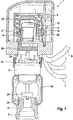
- the adjustment device 1 is mounted on a flow control valve 2.
- the setting device 1 is fastened to the flow control valve 2 by means of a flange 27.
- the flow control valve 2 is built into a return manifold 14.
- the return manifold 14 has a connection piece 18 screwed into it, which connects the return manifold 14 to a consumer loop 3, not shown in detail.
- the flow control valve 2 can also be built into the return manifold 14 in some other way.
- the connection piece 18 can also be pressed, glued, soldered, welded or otherwise fastened into the return manifold.
- the adjustment device 1 comprises an electrically controllable actuator 6.
- the electrically controllable actuator 6 contains an actuating means 20 that is movable in the axial direction.
- the longitudinal axis of the actuating means 20 also coincides with the longitudinal axis of the electrically controllable actuator 6.
- the actuating means 20 is arranged within the electrically controllable actuator 6, has a component 21 which can be changed in length in the axial direction, for example an expansion element 21, in particular a wax cartridge, and is pretensioned by a spiral spring 22 arranged concentrically coaxially with it.
- variable-length component 21 can also be designed as an electrical mini-actuator, although this is often not considered for reasons of cost and because of the suspected noise development.
- spiral spring 22 another suitable means, for example an annular spring assembly or the like, can also generate a pretension.
- the electrically controllable actuator 6 receives signals from a temperature sensor (not shown) on the return manifold 14 with regard to the output-side return temperature T return of the heat transfer medium flowing through.
- the electrically controllable actuator 6 also receives temperature signals via the lines 7 from a temperature sensor on the flow distributor (not shown here) with regard to an inlet-side flow temperature T flow of the heat transfer medium flowing through.
- Another electrical line 9 forms in the present embodiment an interface to an in Figure 1 thermostat not shown.
- Computing means 8 contained in setting device 1 process the signals received via lines 7 and 9 and output corresponding commands or control signals to electrically controllable actuator 6, with the aid of which the expansion element 21 in actuating means 20 is activated or deactivated. In this way, a defined adjustment path or stroke of the actuating means 20 is ultimately realized in the axial direction.
- the actuating means 20 presses in the axial direction on an actuating pin 23 of the flow control valve 2 and thus actuates the same.
- the longitudinal axis of the actuating means 20 and the actuating pin 23 as well as of the flow control valve 2 coincide.
- Axial actuation of the valve pin 23 lifts a valve head, designed as a valve disk 24 in the exemplary embodiment, from a valve seat 25 and thus defines a valve position that corresponds to a specific opening position of the flow control valve 2 or a specific valve opening cross-section.
- the position detection means 15 consists of a magnet 16 which is assigned to the electrically controllable actuator 6 via a radially outwardly protruding arm 26 and is connected to the actuation means 20. In this way, the magnet 16 moves in the axial direction parallel to the expansion element 21 or parallel to the valve plate 24, makes the same stroke or adjustment path with this, and serves as a reference for the respective stroke.
- a Hall sensor 17 arranged opposite the magnet 16 is a further component of the position detection means 15 Cross section of the flow control valve 2 is determined.
- Adjustment device 1 according to the invention shown is in multiple copies in the in Figure 2 explained temperature control system 10 according to the invention installed.
- the exemplary embodiment of the temperature control system 10 according to Fig. 2 contains a distributor device 11 with three adjustment devices 1 which are mounted on the respectively assigned flow control valve 2 by means of respective flanges 27.
- the respective flow valves 2 are built into one of the return manifolds 14.
- the latter On the opposite side of the adjustment device 1 or on the underside of the return manifold 14 viewed in the installation direction, the latter has a connector 18 via which the connection to the respective consumer loop 3 is established.
- the respective consumer loop 3 forms a respective heat exchanger 30.
- the respective output-side return temperature T return of the heat transfer medium flowing through the respective consumer loop 3 is detected with the return temperature sensor 7b.
- the return temperature sensor 7b could also be attached at another suitable point for detecting the respective return temperature, for example immediately after the connection piece 18 on the pipe wall of the consumer loop 3 shown as a line.
- the temperature control system 10 also has a flow distributor 13.
- the flow distributor 13 contains three connection pieces 28 for the three consumer loops 3 shown.
- a temperature detection means 7 is again attached to each connection piece 28, for example a flow temperature sensor 7a, in order to control the respective inlet-side flow temperature T flow of the heat transfer medium flowing through the respective consumer loop 3 capture.
- the flow temperature sensor 7a could also be attached at another suitable point for detecting the respective flow temperature, for example immediately after the connection piece 28 on the pipe wall of the consumer loop 3 shown as a line.
- the flow distributor 13 is connected to the return distributor 14 via a line 29 which contains a temperature control source 4 and a pump 5. With the pump 5, the liquid heat transfer medium, which has been charged with thermal energy or possibly cooled by the temperature control source 4, can be circulated. The heat transfer medium flowing through is transported by the pump 5 to the flow distributor 13, there the heat transfer medium flows into the three consumer loops 3 shown here and through them back to the return distributor 14, the respective flow rate being determined by the flow cross-section of the respective flow control valve 2, which is installed in the return distributor 14 are determined. From the return manifold 14, the flowing heat transfer medium that is pooled there flows back to the pump 5 or to the temperature control source 4.
- a thermostat 12 assigned to the respective consumer loop 3 issues a control signal when there is a need for temperature control.
- the control signal is transmitted from the thermostat 12, for example via an interface 9, here a cable, to the setting device 1.
- the interface 9 could, however, also be designed as a wireless connection.
- the respective setting device 1 determines the respective opening cross-section of the respective flow control valve 2 by means of the respective calculation means 8 as a function of the activation signal or deactivation signal of the respective thermostat 12 and the respectively assigned signals or data of the flow and return temperatures.
- the in the temperature control system 10 according to Figure 2 built-in adjustment devices 1 according to Fig. 1 are in Fig. 3 once again in a block diagram that shows the system components for self-regulation according to the invention.
- a thermostat 12 in particular a room thermostat in a living room of a building, outputs a signal.
- the signal from the thermostat 12 is transferred to an ECU of the setting device 1.
- the ECU also receives temperature signals or data, such as the return temperature T return and the flow temperature T flow .
- a computation means 8, which contains the ECU, is set up to carry out an electrical control of the actuator 6 of the setting device 1, not shown here, in order to implement a stroke of the valve, or the predetermined opening position of the flow control valve 2 assigned to a specific flow cross section adjust.
- the setting device 1 further comprises a time recording means (not shown here) and a storage means which are set up to record and store a previous or current activation duration of the activation signal from the thermostat 12 and / or a deactivation duration between two activations or deactivations, the calculation means 8 with the ECU contained therein is set up to variably determine the temperature spread .DELTA.T setpoint based on an activation duration and / or a deactivation duration.
- Fig. 4 a flowchart is shown which represents steps for a determination of the temperature spread ⁇ T setpoint in the self-regulation according to the invention.
- step S150 which follows on from steps S100 to S140, the possible values of the desired value ⁇ T Soll are limited, specifically to a temperature spread profile between five to fifteen Kelvin or five to fifteen degrees.
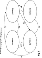
- Fig. 5 a state machine for the representation of logical links in the self-regulation according to the invention is explained.
- the valve position of the flow control valve 2 is regulated.
- the actual spread dT_Ist or ⁇ T Ist is calculated or determined.
- the difference dT_diff or .DELTA.T control difference from the setpoint spread dT_Soll or .DELTA.T setpoint and actual spread becomes dT_Ist or ⁇ T Ist calculated.
- the valve opening cross-section, the valve lift or the valve travel sV is calculated, the same for example regulated via a PID controller, in particular via an I controller, and the valve travel is limited, for example to a minimum of 10 percent. This has the advantage that undesired flow noises are minimized.
- the heating duration is calculated in the controller cycle, which is set to 10 seconds, for example.
- state 2 the valve position is held.
- the actual spread dT_Ist or ⁇ T Ist is calculated.
- the duration or activation duration is counted in the controller cycle.
- the controller cycle is, for example, 10 seconds.
- the heating time is also calculated every 10 seconds.
- the controller cycle can be set to integer seconds between 1 second and 30 seconds; it is preferably set to 5 to 15 seconds, particularly preferably to 10 seconds.
- the target spread is calculated.
- the setpoint dT_Soll or ⁇ T Soll is calculated and the heating duration is then zeroed or reset to zero.
- State 1 is linked to state 2 via function F10.
- function F10 it is checked whether the control difference ⁇ T control difference , ie the amount of the difference ⁇ T setpoint minus ⁇ T actual or from dT_Soll - dT_Ist is less than dT_diff_Max, ie it is checked whether
- dTSoll - dTIst ⁇ dT _ Diff _ Max .
- State 2 is linked in the direction of state 1 via function F20.
- Function F20 checks whether the amount from dT_Soll - dT_Ist is also greater than twice dT_diff_Max and at the same time the duration is greater than or equal to 10 minutes, ie it is checked whether
- State 2 is linked in the direction of state 4 via function F30.
- State 4 is linked to state 3 via function F40.
- RT stands for the control signal from the room thermostat.
- State 3 is in turn linked in the direction of state 2 via function F50.
- function 50 it is determined whether the room thermostat issues a control signal or activation signal.
- State 4 is linked in the direction of state 1 via function F60.
- State 1 is linked to state 4 via function F70.
- Function F70 checks whether the heating duration is longer than 4 hours, ie it is checked whether heating duration > 4 hours.
- the heating time given here as an example of 4 hours can also be set to a suitable value of 2 to 6 hours, for example 3, 4 or 5 hours.
- the present invention thus creates for the first time a setting device 1 for the self-regulating setting of a flow control valve 2 of a consumer loop 3 with heat exchanger 30, in particular in a temperature control system 10 for buildings with a temperature control source 4, a liquid heat transfer medium and a pump 5.
- the invention provides for the first time a distributor device 11 for the self-regulating distribution of a liquid heat transfer medium to at least two or more consumer loops 3 with heat exchangers 30, each of which includes a flow control valve 2, in a temperature control system 10 with a temperature control source 4 and a pump 5, wherein the distribution device 11 has a flow distributor 13 and a return distributor 14.
- the consumer loops 3 are brought together on the input side and the output side, the flow valves 2 being arranged on the flow distributor 13 or the return distributor 14.
- the invention proposes methods suitable for this for the first time.
Claims (22)
- Dispositif de réglage (1) pour le réglage autorégulant d'une soupape de régulation de débit (2) d'une boucle d'utilisateur (3) avec un échangeur de chaleur (30) dans un système d'équilibrage de température (10) de locaux d'un immeuble avec une source d'équilibrage de température (4), un liquide caloporteur et une pompe (5), le dispositif de réglage (1) comprenant :- un organe de réglage (6) à commande électrique conçu pour être couplé à la soupape de régulation de débit (2) pour régler et permettre la saisie d'une position d'ouverture de la soupape de réglage de débit (2) entre une position fermée et une position ouverte, de manière graduelle ou pas à pas par le dispositif de réglage (1),- un moyen de saisie de température (7) pour saisir une température montante (TVorlauf) côté entrant de la boucle d'utilisateur (3), ainsi qu'une température de retour (TRücklauf) côté sortant du liquide caloporteur en circulation,- un moyen de calcul (8) conçu pour calculer une commande électrique de l'organe de commande (6) qui correspond à une position d'ouverture prédéfinie de la vanne de réglage de débit (2) - associée à une certaine section de passage -, en se fondant sur une différence de régulation (ΔTRegeldifferenz),cette différence de régulation, à calculer (ΔTRegeldifferenz) étant formée entre :* une différence de température (ΔIst) de la température montante (TVorlauf) saisie côté entrant par des moyens de saisie de température (7) et une température de retour (TRücklauf), côté sortant, et* et un écart de température (ΔTSoll) prédéfini par le moyen de calcul (8) entre la température de retour (TRücklauf) côté sortant et la température montante (TVorlauf) côté entrant, c'est-à-dire la valeur de la différence (ΔTSoll) moins (ΔIst),- une interface (9) pour recevoir un signal d'activation externe pour activer le moyen de calcul (8) et/ou le dispositif de réglage (1),caractérisé en ce que- le dispositif de réglage (1) comprend un moyen de saisie du temps et un moyen de mémoire conçus pour saisir et enregistrer une durée d'activation antérieure ou actuelle du signal d'activation et/ou une durée de désactivation entre deux activations, et- le moyen de calcul (8) est conçu pour déterminer l'écart de température (ΔTSoll) en se fondant sur la durée d'activation et/ou la durée de désactivation.
- Dispositif de réglage (1) pour le réglage autorégulant d'une vanne de réglage de débit (2) d'une boucle d'utilisateur (3) selon la revendication 1,
caractérisé en ce que
le dispositif de réglage (1) est conçu pour, pendant une durée d'activation, fournir la commande électrique calculée par le moyen de calcul (8) à l'organe de réglage (6) et pendant une durée de désactivation, n'envoyer aucune commande électrique ou une commande électrique prédéfinie correspondant à la position fermée de la vanne de réglage de débit à l'organe de réglage (6). - Dispositif de réglage (1) pour le réglage autorégulant d'une vanne de réglage de débit (2) d'une boucle d'utilisateur (3) selon la revendication 1 ou 2,
caractérisé en ce que
le dispositif de réglage (1) est conçu pour couper l'alimentation électrique du moyen de calcul (8) et/ou du dispositif de réglage (1) pendant une durée de désactivation. - Dispositif de réglage (1) pour le réglage autorégulant d'une vanne de réglage de débit (2) d'une boucle d'utilisateur (3) selon l'une des revendications 1 à 3,
caractérisé en ce que
le moyen de calcul (8) est conçu pour enregistrer au moins une valeur d'une position d'ouverture antérieure de la vanne de réglage de débit (2) dans la mémoire. - Dispositif de réglage (1) pour le réglage autorégulant d'une vanne de réglage de débit (2) d'une boucle d'utilisateur (3) selon l'une des revendications 1 à 4,
caractérisé en ce que
la mémoire contient une valeur de référence préalablement enregistrée pour la durée d'activation et/ou d'une valeur de référence préalablement enregistrée pour la durée de désactivation. - Dispositif de réglage (1) pour le réglage autorégulant d'une vanne de réglage de débit (2) d'une boucle d'utilisateur (3) selon l'une des revendications 1 à 5,
caractérisé en ce que
la mémoire contient une plage de valeurs mémorisées au préalable pour l'écart de température. - Dispositif de réglage (1) pour le réglage autorégulant d'une vanne de réglage de débit (2) d'une boucle d'utilisateur (3) selon l'une des revendications 1 à 6,
caractérisé en ce que
la mémoire contient un champ de caractéristiques préalablement mémorisées avec des valeurs associées de durée d'activation et/ou de durée de désactivation et des écarts de température (ΔTSoll) prédéfinis pour déterminer l'écart de température (ΔTSoll). - Dispositif de réglage (1) pour le réglage autorégulant d'une vanne de réglage de débit (2) d'une boucle d'utilisateur (3) selon l'une des revendications 1 à 7,
caractérisé en ce que
la mémoire contient une logique de commande mémorisée au préalable pour déterminer l'écart de température (ΔTSoll). - Dispositif de réglage (1) pour le réglage autorégulant d'une vanne de réglage de débit (2) d'une boucle d'utilisateur (3) selon l'une des revendications 1 à 8,
caractérisé en ce que
le dispositif de réglage (1) est conçu pour modifier l'écart de température (ΔTSoll) en fonction de la température montante (TVorlauf), et/ou le dispositif de réglage (1) est conçu pour modifier une largeur de bande de l'écart de température (ΔTSoll) en fonction de la température montante (TVorlauf), et/ou
le dispositif de réglage (1) est conçu pour recevoir par l'interface (9) d'autres signaux externes avec des paramètres de fonctionnement du système d'équilibrage de température (10) et le moyen de calcul (8) est conçu pour adapter l'écart de température (ΔTSoll) en fonction des paramètres de fonctionnement. - Système d'équilibrage de température (10) pour équilibrer, de manière autorégulée la température de locaux d'un immeuble comprenant une source d'équilibrage de température (4), au moins une boucle d'utilisateur (3) avec un échangeur de chaleur (30) qui comporte une vanne de régulation de débit (2) ainsi qu'un liquide caloporteur et une pompe (5), au moins un thermostat (12) installé dans un local, un moyen d'entrée pour entrer une valeur correspondant à une température de local prédéfinie (TRaum-Soll) ainsi qu'une interface (9) pour émettre un signal d'activation pour au moins une boucle d'utilisateur (3) dans le local,
dans lequel
le thermostat (12) est conçu pour répondre à une température de local effective (TRaum-Ist), le thermostat (12) émettant le signal d'activation aussi longtemps qu'une tolérance d'écart entre la température de local prédéfinie (TRaum-Soll) et la température réelle de local (TRaum-Ist) est dépassée, caractérisé en ce que
le système d'équilibrage de température (10), pour au moins une boucle d'utilisateur (3), comprend un dispositif de réglage (1) selon l'une des revendications 1 à 9 coopérant avec la vanne de réglage de débit (2) de la boucle d'utilisateur (3) et auquel est associé un signal d'activation ou un signal de désactivation du thermostat (12) installé dans le même local que la boucle d'utilisateur (3). - Système d'équilibrage de température (10) pour l'équilibrage autorégulant de la température de locaux d'un immeuble selon la revendication 10,
caractérisé en ce qu'
un thermostat (12) et deux ou plusieurs boucles d'utilisateur (3) sont installés dans un local de l'immeuble. - Système d'équilibrage de température (10) pour l'équilibrage autorégulant de la température de locaux d'un immeuble selon l'une des revendications 10 ou 11,
caractérisé en ce que
le thermostat (12) comporte un élément bimétal qui répond à la température effective du local (TRaum-Ist) et actionne l'émission du signal d'activation ou du signal de désactivation. - Système d'équilibrage de température pour l'équilibrage autorégulant de la température de locaux d'un immeuble selon l'une des revendications 10 à 12,
caractérisé en ce que
le signal d'activation ou le signal de désactivation est un signal binaire qui comprend un état de marche avec un niveau de signal au-dessus d'une valeur de niveau prédéfinie et un état de coupure sans niveau de signal ou un niveau de signal en dessous d'une valeur de niveau prédéfinie. - Système d'équilibrage de température (10) pour l'équilibrage autorégulant de la température de locaux d'un immeuble selon l'une des revendications 10 à 13,
caractérisé en ce que
le thermostat (12) comprend un microcalculateur et un capteur de température pour saisir la température effective du local (TRaum-Ist),
* le thermostat (12) saisissant l'évolution de la température effective du local (TRaum-Ist) et l'enregistrant pendant et/ou après que le signal d'activation ou le signal de désactivation n'ait été émis, et
le thermostat (12) et le dispositif de réglage (1) sont conçus pour communiquer les données relatives à l'évolution des températures effectivement saisies du local (TRaum-Ist). - Système d'équilibrage de température pour l'équilibrage autorégulant de la température de locaux d'un immeuble selon l'une des revendications 10 à 14,
caractérisé en ce que
le signal d'activation et/ou le signal de désactivation sont transmis par des interfaces sans fil (9) du thermostat (12) vers le dispositif de réglage (1) associé. - Dispositif de distribution (11) pour la répartition auto-régulante d'un liquide caloporteur vers au moins une ou plusieurs boucles d'utilisateur (3) avec un échangeur de chaleur (30) comprenant une vanne de régulation de débit (2) dans un système d'équilibrage de température (10) avec une source d'équilibrage (4) et une pompe (5),- un répartiteur montant (13) et un répartiteur de retour (14) réunissant les boucles d'utilisateur (3) côté entrée et côté sortie, les vannes de régulation de débit (2) étant installées dans le distributeur montant (13) ou le distributeur de retour (14),caractérisé en ce que
le dispositif répartiteur (11) comprend pour chaque vanne de régulation de débit (2), un dispositif de réglage (1) selon l'une des revendications 1 à 9, pour le réglage autorégulant des boucles d'utilisateur (3). - Procédé de réglage autorégulant d'un débit de liquide caloporteur dans une boucle d'utilisateur (3) avec un échangeur de chaleur (30) dans un système d'équilibrage de température (10) pour des immeubles avec une source d'équilibrage (4) et une pompe (5),
le procédé comprenant au moins les étapes suivantes consistant à :a) saisir une température montante (TVorlauf) côté entrant et une température de retour (TRücklauf) côté sortant du liquide caloporteur circulant dans la boucle d'utilisateur (3),b) calculer une différence de régulation (ΔTRegeidifferenz) entre :* une différence de température (ΔTist) correspondant à la température montante (TVorlauf) côté entrant et la température de retour (TRücklauf) côté sortant, et* un écart de température prédéfini (ΔTSoll), c'est-à-dire la valeur de la différence (ΔTSoll) moins (ΔTist),c) calculer et régler une section de passage réglable dans la boucle d'utilisateur (3) en se fondant sur la différence de réglage (ΔTRegeldifferenz),caractérisé par les étapes consistant à :d) saisir une durée d'activation et/ou une durée de désactivation antérieures ou actuelles de la boucle d'utilisateur (3), ete) déterminer l'écart de température variable (ΔTSoll) de la température de retour (TRücklauf) côté sortant et la température montante (TVorlauf) côté montant en se fondant sur la durée d'activation et/ou la durée de désactivation. - Procédé de réglage autorégulant d'un débit de liquide caloporteur dans une boucle d'utilisateur (3) selon la revendication 17,
caractérisé en ce qu'
on détermine un plus petit écart de température (ΔTSoll) si au moins une durée d'activation ou une durée de désactivation antérieures est supérieure à une valeur de référence, ou
on détermine un écart de température (ΔTSoll) plus grand si au moins une durée d'activation ou une durée de désactivation antérieures est inférieure à la valeur de référence. - Procédé de réglage autorégulant d'un débit de liquide caloporteur dans une boucle d'utilisateur (3) selon la revendication 17 ou 18,
caractérisé en ce qu'
on détermine l'écart de température (ΔTSoll) en se fondant sur l'évolution de durée d'activation et/ou de durée de désactivation, successives, antérieures. - Procédé de répartition autorégulant d'un liquide caloporteur entre au moins deux ou plusieurs boucles d'utilisateur (3) avec un échangeur de chaleur dans un système d'équilibrage de température (10) pour des immeubles ayant une source d'équilibrage de température (4) et une pompe (5),
procédé caractérisé en ce que
pour chaque boucle d'utilisateur (3) on effectue le procédé de réglage autorégulant du débit de liquide caloporteur dans une boucle d'utilisateur (3) externe, activable selon l'une des revendications 17-19. - Dispositif de réglage (1) pour le réglage autorégulant d'une vanne de réglage de débit (2) selon l'une des revendications 1 à 9, le dispositif de réglage (1) comprenant en outre :- un moyen de saisie de position (15) conçu pour saisir la position actuelle de l'organe de réglage (6).
- Dispositif de réglage (1) pour le réglage autorégulant d'une vanne de réglage de débit (2) selon la revendication 21,
caractérisé en ce que
le moyen de saisie de position (15) se compose d'un aimant (16) et d'un capteur à effet Hall (17) associé à l'aimant (16).
Priority Applications (3)
| Application Number | Priority Date | Filing Date | Title |
|---|---|---|---|
| PL18786704T PL3665542T3 (pl) | 2017-10-10 | 2018-10-09 | Samoregulujące urządzenie nastawcze dla zaworu do regulujacji przepływu, system do wyrównywania temperatury, jak również urządzenie rozdzielcze z tym samym oraz odnośny sposób |
| SI201830184T SI3665542T1 (sl) | 2017-10-10 | 2018-10-09 | Samoregulirna nastavljalna naprava za regulirni ventil pretoka, sistem za krmiljenje temperature kot tudi distribucijska naprava z le-tem in pa postopek za to |
| HRP20210187TT HRP20210187T1 (hr) | 2017-10-10 | 2021-02-02 | Samoregulatorni prilagodni uređaj za protočni upravljački ventil, temperaturni upravljački sustav i distribucijski uređaj koji ga sadrže, kao i postupak u svezi istoga |
Applications Claiming Priority (2)
| Application Number | Priority Date | Filing Date | Title |
|---|---|---|---|
| DE102017123560.4A DE102017123560A1 (de) | 2017-10-10 | 2017-10-10 | Selbstregulierende Einstellvorrichtung für ein Durchflussregelventil, ein Temperierungssystem als auch eine Verteilervorrichtung mit derselben, sowie Verfahren hierzu |
| PCT/EP2018/077418 WO2019072813A1 (fr) | 2017-10-10 | 2018-10-09 | Dispositif de réglage autorégulateur pour une soupape de régulation de débit, système de mise en température en tant qu'un dispositif de distribution pourvu dudit dispositif de réglage ainsi que procédés correspondants |
Publications (2)
| Publication Number | Publication Date |
|---|---|
| EP3665542A1 EP3665542A1 (fr) | 2020-06-17 |
| EP3665542B1 true EP3665542B1 (fr) | 2020-12-02 |
Family
ID=63862110
Family Applications (1)
| Application Number | Title | Priority Date | Filing Date |
|---|---|---|---|
| EP18786704.9A Active EP3665542B1 (fr) | 2017-10-10 | 2018-10-09 | Dispositif de réglage autorégulé pour une vanne de régulation de fluide, système de thermorégulation et un système de distribution comprenant celui-ci, ainsi que procédé associé |
Country Status (13)
| Country | Link |
|---|---|
| EP (1) | EP3665542B1 (fr) |
| KR (1) | KR102307318B1 (fr) |
| CN (1) | CN111201500B (fr) |
| CA (1) | CA3076442C (fr) |
| DE (1) | DE102017123560A1 (fr) |
| DK (1) | DK3665542T3 (fr) |
| ES (1) | ES2842023T3 (fr) |
| HR (1) | HRP20210187T1 (fr) |
| HU (1) | HUE051820T2 (fr) |
| PL (1) | PL3665542T3 (fr) |
| RU (1) | RU2735734C1 (fr) |
| SI (1) | SI3665542T1 (fr) |
| WO (1) | WO2019072813A1 (fr) |
Families Citing this family (7)
| Publication number | Priority date | Publication date | Assignee | Title |
|---|---|---|---|---|
| DE102018127381A1 (de) | 2018-11-02 | 2020-05-07 | Straub Kg | Selbstregulierende Einstellvorrichtung für ein Durchflussregelventil und Verfahren zur selbstregulierenden Einstellung |
| DE102018127385A1 (de) | 2018-11-02 | 2020-05-07 | Straub Kg | Einstellvorrichtung mit einer optischen Datenschnittstelle, optisches Datenübertragungssystem und Verfahren |
| DE102019120126B4 (de) * | 2019-07-25 | 2021-08-05 | Straub Kg | Einstellvorrichtung und Verfahren zur Ermittlung eines hydraulischen Schwellwerts eines Ventils |
| DE102019120117B4 (de) | 2019-07-25 | 2021-08-19 | Straub Kg | Einstellvorrichtung und Verfahren zur verbesserten Feinregulierung eines Ventilspalts |
| CN112963899B (zh) * | 2021-04-08 | 2023-05-05 | 中嘉能源管理(北京)有限公司 | 一种多阀门多模式调节的精确控制方法及系统 |
| CN113639437A (zh) * | 2021-08-09 | 2021-11-12 | 青岛海尔空调器有限总公司 | 空调器控制方法、装置、电子设备、存储介质及空调器 |
| CN115751663A (zh) * | 2022-11-28 | 2023-03-07 | 贵州电网有限责任公司 | 一种中央空调外机散热负荷自动调节装置和方法 |
Citations (1)
| Publication number | Priority date | Publication date | Assignee | Title |
|---|---|---|---|---|
| DE102013014833A1 (de) * | 2013-09-10 | 2015-03-12 | Stiebel Eltron Gmbh & Co. Kg | Verfahren zur Regelung einer Temperatur |
Family Cites Families (28)
| Publication number | Priority date | Publication date | Assignee | Title |
|---|---|---|---|---|
| DE19911866B4 (de) * | 1999-03-17 | 2018-10-18 | Xylem Ip Holdings Llc | Vorrichtung zum Abgleich von Heizkreisen in Großflächen-Heizungsanlagen |
| EP1393004B1 (fr) * | 2001-05-03 | 2008-08-27 | Matts Lindgren | Procede et systeme permettant de reguler la temperature du flux sortant d'un echangeur de chaleur et de mesurer la chaleur produite |
| DE202004000201U1 (de) * | 2004-01-09 | 2004-04-01 | Fließ, Fernando, Dipl.-Ing. | Elektrischer Signalgeber für thermostatische Stellantriebe |
| EP1852660A1 (fr) * | 2006-05-03 | 2007-11-07 | Roth Werke GmbH | Procédé et dispositif pour le chauffage et/ou refroidissement d'un bâtiment |
| DE102006052124A1 (de) | 2006-11-06 | 2008-05-15 | Danfoss A/S | Abgleichsystem für eine Fußbodentemperierungs-Anordnung |
| US20090314484A1 (en) | 2008-06-18 | 2009-12-24 | Akz Technologies Llc | Standalone flow rate controller for controlling flow rate of cooling or heating fluid through a heat exchanger |
| DE102009004319A1 (de) | 2009-01-10 | 2010-07-22 | Henry Klein | Verfahren, Computerprogramm und Regelgerät für einen temperaturbasierten hydraulischen Abgleich |
| WO2011154003A2 (fr) * | 2010-06-10 | 2011-12-15 | Danfoss A/S | Système d'alimentation de chaleur à un tuyau à régulation de débit |
| JP5965895B2 (ja) * | 2011-02-22 | 2016-08-10 | ジョンソンコントロールズ ヒタチ エア コンディショニング テクノロジー(ホンコン)リミテッド | 冷凍サイクル装置 |
| JP5501282B2 (ja) * | 2011-04-07 | 2014-05-21 | 三菱電機株式会社 | ヒートポンプシステム及びヒートポンプシステムの制御方法 |
| GB201112769D0 (en) | 2011-07-26 | 2011-09-07 | Armstrong Peter M | Immersion controller |
| JP5958912B2 (ja) * | 2011-08-24 | 2016-08-02 | パナソニックIpマネジメント株式会社 | 暖房システムの制御方法及び暖房システム |
| DE102012109206B4 (de) * | 2011-11-30 | 2019-05-02 | Hanon Systems | Ventil-Sensor-Anordnung |
| CH705980B1 (fr) * | 2012-01-12 | 2017-10-31 | Neurobat Ag | Système de régulation de la température dans une installation de chauffage d'un immeuble. |
| CH706146A2 (de) | 2012-02-29 | 2013-08-30 | Oblamatik Ag | Verfahren und System zum Temperieren von Bauteilen. |
| CN103017252B (zh) * | 2012-11-19 | 2015-06-17 | 江苏大学 | 一种室内电热膜地暖控制装置及控制方法 |
| CN203478425U (zh) * | 2013-10-09 | 2014-03-12 | 樱花卫厨(中国)股份有限公司 | 采暖设备的一键智能控制系统 |
| DK2871423T3 (en) * | 2013-11-07 | 2017-08-28 | Grundfos Holding As | Control method for a heating and / or cooling system with at least one load circuit and distributor device for a heating and / or cooling system |
| IL230147A (en) * | 2013-12-24 | 2015-02-26 | Ariel Cohen | Controller programmed for water heating system |
| DE102014202738B4 (de) | 2014-02-14 | 2022-11-17 | Robert Bosch Gmbh | Verfahren zum automatisierten hydraulischen Abgleich einer Heizungsanlage |
| WO2015142879A1 (fr) | 2014-03-18 | 2015-09-24 | Imi Hydronic Engineering, Inc. | Composants intelligents de rattrapage destinés à être utilisés dans un système de transfert de fluide |
| WO2015148596A1 (fr) * | 2014-03-28 | 2015-10-01 | Google Inc. | Dispositif autodidactif de commande de l'environnement pouvant être relocalisé par un utilisateur |
| PL3012705T3 (pl) * | 2014-10-22 | 2017-07-31 | Danfoss A/S | Układ zaworowy wymiennika ciepła, system grzewczy i sposób działania systemu grzewczego |
| WO2016086986A1 (fr) * | 2014-12-03 | 2016-06-09 | Grundfos Holding A/S | Ensemble convertisseur électronique à des fins de montage en rattrapage sur une partie externe d'un boîtier d'une unité de pompage |
| US10077908B2 (en) * | 2014-12-08 | 2018-09-18 | Us Pump Corp. | Method for heating and/or cooling of building interior by use of variable speed pump, programmable logic controller, and temperature sensors at heating/cooling inlet and outlet for maintaining precise temperature |
| US10465919B2 (en) * | 2015-07-28 | 2019-11-05 | B2 Products Ltd. | Modular track wiring assembly for a hydronic system |
| DE102015222110A1 (de) | 2015-11-10 | 2017-05-11 | Robert Bosch Gmbh | Verfahren zum Durchführen eines automatisierten hydraulischen Abgleichs, Ventil und Heizungsanlage hierzu |
| CN106051886A (zh) * | 2016-07-01 | 2016-10-26 | 国网冀北节能服务有限公司 | 一种基于固体蓄热的供热系统 |
-
2017
- 2017-10-10 DE DE102017123560.4A patent/DE102017123560A1/de active Pending
-
2018
- 2018-10-09 RU RU2020112291A patent/RU2735734C1/ru active
- 2018-10-09 PL PL18786704T patent/PL3665542T3/pl unknown
- 2018-10-09 ES ES18786704T patent/ES2842023T3/es active Active
- 2018-10-09 KR KR1020207009988A patent/KR102307318B1/ko active IP Right Grant
- 2018-10-09 CN CN201880065414.9A patent/CN111201500B/zh active Active
- 2018-10-09 CA CA3076442A patent/CA3076442C/fr active Active
- 2018-10-09 SI SI201830184T patent/SI3665542T1/sl unknown
- 2018-10-09 WO PCT/EP2018/077418 patent/WO2019072813A1/fr active Search and Examination
- 2018-10-09 HU HUE18786704A patent/HUE051820T2/hu unknown
- 2018-10-09 DK DK18786704.9T patent/DK3665542T3/da active
- 2018-10-09 EP EP18786704.9A patent/EP3665542B1/fr active Active
-
2021
- 2021-02-02 HR HRP20210187TT patent/HRP20210187T1/hr unknown
Patent Citations (1)
| Publication number | Priority date | Publication date | Assignee | Title |
|---|---|---|---|---|
| DE102013014833A1 (de) * | 2013-09-10 | 2015-03-12 | Stiebel Eltron Gmbh & Co. Kg | Verfahren zur Regelung einer Temperatur |
Also Published As
| Publication number | Publication date |
|---|---|
| RU2735734C1 (ru) | 2020-11-06 |
| KR20200047684A (ko) | 2020-05-07 |
| DK3665542T3 (da) | 2020-12-21 |
| CA3076442A1 (fr) | 2019-04-18 |
| SI3665542T1 (sl) | 2021-03-31 |
| ES2842023T3 (es) | 2021-07-12 |
| WO2019072813A1 (fr) | 2019-04-18 |
| PL3665542T3 (pl) | 2021-07-19 |
| DE102017123560A1 (de) | 2019-04-11 |
| CN111201500B (zh) | 2021-08-10 |
| KR102307318B1 (ko) | 2021-10-01 |
| HUE051820T2 (hu) | 2021-03-29 |
| EP3665542A1 (fr) | 2020-06-17 |
| HRP20210187T1 (hr) | 2021-03-19 |
| CN111201500A (zh) | 2020-05-26 |
| CA3076442C (fr) | 2022-04-12 |
Similar Documents
| Publication | Publication Date | Title |
|---|---|---|
| EP3665542B1 (fr) | Dispositif de réglage autorégulé pour une vanne de régulation de fluide, système de thermorégulation et un système de distribution comprenant celui-ci, ainsi que procédé associé | |
| EP3593055B1 (fr) | Procédé pour faire fonctionner une installation de chauffage | |
| EP1645928B1 (fr) | Procédé de détermination de l'état d'alimentation d'une surface chauffante et régulateur d'état d'alimentation | |
| EP1936288B1 (fr) | Procédé et système destinés à la détection d'un équilibrage hydraulique d'une installation de chauffage | |
| DE102004017593B3 (de) | Kühl- und/oder Heizvorrichtung | |
| CH706146A2 (de) | Verfahren und System zum Temperieren von Bauteilen. | |
| EP2187136A2 (fr) | Procédé de fonctionnement d'un système de transport d'énergie thermique sur un support fluide | |
| EP0729086B1 (fr) | Procédé et dispositif pour réguler un système de chauffage par température basse | |
| EP3936770A1 (fr) | Système de chauffage à équilibrage hydraulique adaptatif automatique | |
| EP3473939B1 (fr) | Procédé de fonctionnement d'une installation de chauffage et installation de chauffage | |
| DE102010053211A1 (de) | Verfahren zum Betreiben eines Heizungssystems | |
| DE102014102275A1 (de) | Verfahren zur Regelung einer Heizungs- und/oder Klimaanlage und Heizungs- und/oder Klimaanlage hierzu | |
| EP3874338B1 (fr) | Procédé de fonctionnement d'une soupape, unité de commande électronique associée et entraînement de soupape | |
| EP3924670A1 (fr) | Procédé pour réguler une pompe de circulation | |
| DE102019120117B4 (de) | Einstellvorrichtung und Verfahren zur verbesserten Feinregulierung eines Ventilspalts | |
| WO2003023288A1 (fr) | Installation de chauffage central | |
| DE102019120126B4 (de) | Einstellvorrichtung und Verfahren zur Ermittlung eines hydraulischen Schwellwerts eines Ventils | |
| EP0192225A2 (fr) | Procédé et dispositif de régulation de température de locaux | |
| EP3168540A1 (fr) | Procédé d'exécution d'un équilibrage hydraulique automatisé, soupape et installation de chauffage associées | |
| EP3874207B1 (fr) | Dispositif de réglage par régulation automatique pour une soupape de régulation de débit, et procédé de réglage par régulation automatique | |
| EP3739267A1 (fr) | Procédé et unité de réglage d'un circuit de chauffage | |
| WO2023217752A1 (fr) | Procédé de surveillance et/ou de commande d'un système de chauffage | |
| DE102020120043A1 (de) | Heizungssystem mit automatischem adaptivem hydraulischem Abgleich | |
| DE10002787B4 (de) | Heizsystem für einen Raum |
Legal Events
| Date | Code | Title | Description |
|---|---|---|---|
| STAA | Information on the status of an ep patent application or granted ep patent |
Free format text: STATUS: UNKNOWN |
|
| STAA | Information on the status of an ep patent application or granted ep patent |
Free format text: STATUS: THE INTERNATIONAL PUBLICATION HAS BEEN MADE |
|
| PUAI | Public reference made under article 153(3) epc to a published international application that has entered the european phase |
Free format text: ORIGINAL CODE: 0009012 |
|
| STAA | Information on the status of an ep patent application or granted ep patent |
Free format text: STATUS: REQUEST FOR EXAMINATION WAS MADE |
|
| GRAP | Despatch of communication of intention to grant a patent |
Free format text: ORIGINAL CODE: EPIDOSNIGR1 |
|
| STAA | Information on the status of an ep patent application or granted ep patent |
Free format text: STATUS: GRANT OF PATENT IS INTENDED |
|
| 17P | Request for examination filed |
Effective date: 20200313 |
|
| AK | Designated contracting states |
Kind code of ref document: A1 Designated state(s): AL AT BE BG CH CY CZ DE DK EE ES FI FR GB GR HR HU IE IS IT LI LT LU LV MC MK MT NL NO PL PT RO RS SE SI SK SM TR |
|
| AX | Request for extension of the european patent |
Extension state: BA ME |
|
| INTG | Intention to grant announced |
Effective date: 20200617 |
|
| RAP1 | Party data changed (applicant data changed or rights of an application transferred) |
Owner name: EUT EDELSTAHL UMFORMTECHNIK GMBH |
|
| GRAS | Grant fee paid |
Free format text: ORIGINAL CODE: EPIDOSNIGR3 |
|
| GRAA | (expected) grant |
Free format text: ORIGINAL CODE: 0009210 |
|
| STAA | Information on the status of an ep patent application or granted ep patent |
Free format text: STATUS: THE PATENT HAS BEEN GRANTED |
|
| AK | Designated contracting states |
Kind code of ref document: B1 Designated state(s): AL AT BE BG CH CY CZ DE DK EE ES FI FR GB GR HR HU IE IS IT LI LT LU LV MC MK MT NL NO PL PT RO RS SE SI SK SM TR |
|
| DAV | Request for validation of the european patent (deleted) | ||
| DAX | Request for extension of the european patent (deleted) | ||
| REG | Reference to a national code |
Ref country code: GB Ref legal event code: FG4D Free format text: NOT ENGLISH |
|
| REG | Reference to a national code |
Ref country code: AT Ref legal event code: REF Ref document number: 1341629 Country of ref document: AT Kind code of ref document: T Effective date: 20201215 Ref country code: CH Ref legal event code: NV Representative=s name: P&TS SA, CH Ref country code: CH Ref legal event code: EP |
|
| REG | Reference to a national code |
Ref country code: DE Ref legal event code: R096 Ref document number: 502018003204 Country of ref document: DE |
|
| REG | Reference to a national code |
Ref country code: DK Ref legal event code: T3 Effective date: 20201215 |
|
| REG | Reference to a national code |
Ref country code: IE Ref legal event code: FG4D Free format text: LANGUAGE OF EP DOCUMENT: GERMAN |
|
| REG | Reference to a national code |
Ref country code: HR Ref legal event code: TUEP Ref document number: P20210187T Country of ref document: HR |
|
| REG | Reference to a national code |
Ref country code: RO Ref legal event code: EPE |
|
| REG | Reference to a national code |
Ref country code: NL Ref legal event code: FP |
|
| REG | Reference to a national code |
Ref country code: FI Ref legal event code: FGE |
|
| REG | Reference to a national code |
Ref country code: HR Ref legal event code: T1PR Ref document number: P20210187 Country of ref document: HR |
|
| REG | Reference to a national code |
Ref country code: SE Ref legal event code: TRGR |
|
| REG | Reference to a national code |
Ref country code: SK Ref legal event code: T3 Ref document number: E 36442 Country of ref document: SK |
|
| REG | Reference to a national code |
Ref country code: GR Ref legal event code: EP Ref document number: 20210400219 Country of ref document: GR Effective date: 20210316 |
|
| REG | Reference to a national code |
Ref country code: HU Ref legal event code: AG4A Ref document number: E051820 Country of ref document: HU |
|
| PG25 | Lapsed in a contracting state [announced via postgrant information from national office to epo] |
Ref country code: NO Free format text: LAPSE BECAUSE OF FAILURE TO SUBMIT A TRANSLATION OF THE DESCRIPTION OR TO PAY THE FEE WITHIN THE PRESCRIBED TIME-LIMIT Effective date: 20210302 Ref country code: RS Free format text: LAPSE BECAUSE OF FAILURE TO SUBMIT A TRANSLATION OF THE DESCRIPTION OR TO PAY THE FEE WITHIN THE PRESCRIBED TIME-LIMIT Effective date: 20201202 |
|
| PG25 | Lapsed in a contracting state [announced via postgrant information from national office to epo] |
Ref country code: BG Free format text: LAPSE BECAUSE OF FAILURE TO SUBMIT A TRANSLATION OF THE DESCRIPTION OR TO PAY THE FEE WITHIN THE PRESCRIBED TIME-LIMIT Effective date: 20210302 Ref country code: LV Free format text: LAPSE BECAUSE OF FAILURE TO SUBMIT A TRANSLATION OF THE DESCRIPTION OR TO PAY THE FEE WITHIN THE PRESCRIBED TIME-LIMIT Effective date: 20201202 |
|
| REG | Reference to a national code |
Ref country code: LT Ref legal event code: MG9D Ref country code: ES Ref legal event code: FG2A Ref document number: 2842023 Country of ref document: ES Kind code of ref document: T3 Effective date: 20210712 |
|
| PG25 | Lapsed in a contracting state [announced via postgrant information from national office to epo] |
Ref country code: SM Free format text: LAPSE BECAUSE OF FAILURE TO SUBMIT A TRANSLATION OF THE DESCRIPTION OR TO PAY THE FEE WITHIN THE PRESCRIBED TIME-LIMIT Effective date: 20201202 Ref country code: EE Free format text: LAPSE BECAUSE OF FAILURE TO SUBMIT A TRANSLATION OF THE DESCRIPTION OR TO PAY THE FEE WITHIN THE PRESCRIBED TIME-LIMIT Effective date: 20201202 Ref country code: LT Free format text: LAPSE BECAUSE OF FAILURE TO SUBMIT A TRANSLATION OF THE DESCRIPTION OR TO PAY THE FEE WITHIN THE PRESCRIBED TIME-LIMIT Effective date: 20201202 Ref country code: PT Free format text: LAPSE BECAUSE OF FAILURE TO SUBMIT A TRANSLATION OF THE DESCRIPTION OR TO PAY THE FEE WITHIN THE PRESCRIBED TIME-LIMIT Effective date: 20210405 |
|
| REG | Reference to a national code |
Ref country code: DE Ref legal event code: R097 Ref document number: 502018003204 Country of ref document: DE |
|
| PG25 | Lapsed in a contracting state [announced via postgrant information from national office to epo] |
Ref country code: IS Free format text: LAPSE BECAUSE OF FAILURE TO SUBMIT A TRANSLATION OF THE DESCRIPTION OR TO PAY THE FEE WITHIN THE PRESCRIBED TIME-LIMIT Effective date: 20210402 |
|
| PLBE | No opposition filed within time limit |
Free format text: ORIGINAL CODE: 0009261 |
|
| STAA | Information on the status of an ep patent application or granted ep patent |
Free format text: STATUS: NO OPPOSITION FILED WITHIN TIME LIMIT |
|
| REG | Reference to a national code |
Ref country code: HR Ref legal event code: ODRP Ref document number: P20210187 Country of ref document: HR Payment date: 20210921 Year of fee payment: 4 |
|
| PG25 | Lapsed in a contracting state [announced via postgrant information from national office to epo] |
Ref country code: AL Free format text: LAPSE BECAUSE OF FAILURE TO SUBMIT A TRANSLATION OF THE DESCRIPTION OR TO PAY THE FEE WITHIN THE PRESCRIBED TIME-LIMIT Effective date: 20201202 |
|
| 26N | No opposition filed |
Effective date: 20210903 |
|
| PG25 | Lapsed in a contracting state [announced via postgrant information from national office to epo] |
Ref country code: MC Free format text: LAPSE BECAUSE OF FAILURE TO SUBMIT A TRANSLATION OF THE DESCRIPTION OR TO PAY THE FEE WITHIN THE PRESCRIBED TIME-LIMIT Effective date: 20201202 |
|
| PG25 | Lapsed in a contracting state [announced via postgrant information from national office to epo] |
Ref country code: LU Free format text: LAPSE BECAUSE OF NON-PAYMENT OF DUE FEES Effective date: 20211009 |
|
| REG | Reference to a national code |
Ref country code: HR Ref legal event code: ODRP Ref document number: P20210187 Country of ref document: HR Payment date: 20220920 Year of fee payment: 5 |
|
| PG25 | Lapsed in a contracting state [announced via postgrant information from national office to epo] |
Ref country code: CY Free format text: LAPSE BECAUSE OF FAILURE TO SUBMIT A TRANSLATION OF THE DESCRIPTION OR TO PAY THE FEE WITHIN THE PRESCRIBED TIME-LIMIT Effective date: 20201202 |
|
| REG | Reference to a national code |
Ref country code: HR Ref legal event code: ODRP Ref document number: P20210187 Country of ref document: HR Payment date: 20230914 Year of fee payment: 6 |
|
| PGFP | Annual fee paid to national office [announced via postgrant information from national office to epo] |
Ref country code: TR Payment date: 20230920 Year of fee payment: 6 Ref country code: RO Payment date: 20230927 Year of fee payment: 6 Ref country code: IT Payment date: 20230914 Year of fee payment: 6 Ref country code: FI Payment date: 20230915 Year of fee payment: 6 |
|
| PGFP | Annual fee paid to national office [announced via postgrant information from national office to epo] |
Ref country code: SK Payment date: 20230921 Year of fee payment: 6 Ref country code: PL Payment date: 20230915 Year of fee payment: 6 Ref country code: NL Payment date: 20231031 Year of fee payment: 6 Ref country code: HR Payment date: 20230914 Year of fee payment: 6 Ref country code: GR Payment date: 20230925 Year of fee payment: 6 Ref country code: DK Payment date: 20230929 Year of fee payment: 6 Ref country code: BE Payment date: 20230926 Year of fee payment: 6 |
|
| PGFP | Annual fee paid to national office [announced via postgrant information from national office to epo] |
Ref country code: GB Payment date: 20231030 Year of fee payment: 6 |
|
| PGFP | Annual fee paid to national office [announced via postgrant information from national office to epo] |
Ref country code: ES Payment date: 20231102 Year of fee payment: 6 |
|
| PGFP | Annual fee paid to national office [announced via postgrant information from national office to epo] |
Ref country code: SI Payment date: 20230922 Year of fee payment: 6 Ref country code: SE Payment date: 20231017 Year of fee payment: 6 Ref country code: IE Payment date: 20231026 Year of fee payment: 6 Ref country code: HU Payment date: 20230919 Year of fee payment: 6 Ref country code: FR Payment date: 20231023 Year of fee payment: 6 Ref country code: DE Payment date: 20231012 Year of fee payment: 6 Ref country code: CZ Payment date: 20231006 Year of fee payment: 6 Ref country code: CH Payment date: 20231102 Year of fee payment: 6 Ref country code: AT Payment date: 20231024 Year of fee payment: 6 |