EP3664578A1 - Gargerätevorrichtung - Google Patents
Gargerätevorrichtung Download PDFInfo
- Publication number
- EP3664578A1 EP3664578A1 EP19211263.9A EP19211263A EP3664578A1 EP 3664578 A1 EP3664578 A1 EP 3664578A1 EP 19211263 A EP19211263 A EP 19211263A EP 3664578 A1 EP3664578 A1 EP 3664578A1
- Authority
- EP
- European Patent Office
- Prior art keywords
- induction
- target
- heating
- power
- control unit
- Prior art date
- Legal status (The legal status is an assumption and is not a legal conclusion. Google has not performed a legal analysis and makes no representation as to the accuracy of the status listed.)
- Pending
Links
- 238000010411 cooking Methods 0.000 title claims abstract description 93
- 230000006698 induction Effects 0.000 claims abstract description 261
- 238000010438 heat treatment Methods 0.000 claims abstract description 226
- 230000006735 deficit Effects 0.000 claims abstract description 32
- 230000004913 activation Effects 0.000 claims abstract description 20
- 230000000737 periodic effect Effects 0.000 claims abstract description 6
- 230000003252 repetitive effect Effects 0.000 claims abstract description 5
- 238000000034 method Methods 0.000 claims description 22
- 239000003990 capacitor Substances 0.000 claims description 11
- 239000011159 matrix material Substances 0.000 description 38
- 230000001276 controlling effect Effects 0.000 description 8
- 230000008569 process Effects 0.000 description 8
- 230000006870 function Effects 0.000 description 6
- 230000008878 coupling Effects 0.000 description 5
- 238000010168 coupling process Methods 0.000 description 5
- 238000005859 coupling reaction Methods 0.000 description 5
- 238000010586 diagram Methods 0.000 description 5
- 230000005672 electromagnetic field Effects 0.000 description 5
- 230000010363 phase shift Effects 0.000 description 5
- 238000004364 calculation method Methods 0.000 description 4
- 230000001105 regulatory effect Effects 0.000 description 4
- 230000005291 magnetic effect Effects 0.000 description 3
- 239000004065 semiconductor Substances 0.000 description 3
- 230000005684 electric field Effects 0.000 description 2
- 230000001965 increasing effect Effects 0.000 description 2
- 230000007704 transition Effects 0.000 description 2
- 230000033228 biological regulation Effects 0.000 description 1
- 230000008859 change Effects 0.000 description 1
- 238000010276 construction Methods 0.000 description 1
- 230000003247 decreasing effect Effects 0.000 description 1
- 230000001419 dependent effect Effects 0.000 description 1
- 238000001514 detection method Methods 0.000 description 1
- 238000011161 development Methods 0.000 description 1
- 230000018109 developmental process Effects 0.000 description 1
- 238000009826 distribution Methods 0.000 description 1
- 230000009977 dual effect Effects 0.000 description 1
- 230000005294 ferromagnetic effect Effects 0.000 description 1
- 230000005669 field effect Effects 0.000 description 1
- 230000001939 inductive effect Effects 0.000 description 1
- 238000004519 manufacturing process Methods 0.000 description 1
- 229910044991 metal oxide Inorganic materials 0.000 description 1
- 150000004706 metal oxides Chemical class 0.000 description 1
- 230000002441 reversible effect Effects 0.000 description 1
- 230000003595 spectral effect Effects 0.000 description 1
- 238000003860 storage Methods 0.000 description 1
- 230000002123 temporal effect Effects 0.000 description 1
- 230000016776 visual perception Effects 0.000 description 1
Images


Classifications
-
- H—ELECTRICITY
- H05—ELECTRIC TECHNIQUES NOT OTHERWISE PROVIDED FOR
- H05B—ELECTRIC HEATING; ELECTRIC LIGHT SOURCES NOT OTHERWISE PROVIDED FOR; CIRCUIT ARRANGEMENTS FOR ELECTRIC LIGHT SOURCES, IN GENERAL
- H05B6/00—Heating by electric, magnetic or electromagnetic fields
- H05B6/02—Induction heating
- H05B6/06—Control, e.g. of temperature, of power
- H05B6/062—Control, e.g. of temperature, of power for cooking plates or the like
- H05B6/065—Control, e.g. of temperature, of power for cooking plates or the like using coordinated control of multiple induction coils
Definitions
- the invention relates to a cooking device according to the preamble of claim 1 and a method for operating a cooking device according to the preamble of claim 11.
- Cooking devices and in particular hobs are already known from the prior art, which have inductors which are operated with matched heating frequencies to avoid acoustically perceptible coupling noises, control schemes for controlling inductors for heating cooking utensils as a result of increased customer requirements for control quality and functionality of a cooktop can be determined in a complex process of finding and calculating, which places high demands on production and on built-in components and therefore results in high costs.
- the publication EP 1 951 003 B1 discloses in this context a method for the simultaneous, inductive operation of two inductors of an induction hob to avoid the occurrence of coupling noises and an uneven power network load, the inductors together with a first heating frequency and in a second time interval with the method in a first time interval a second heating frequency which is different from the first heating frequency.
- the publication also discloses US 7,910,865 B2 a method for operating an induction hob, in which the inductors are operated with a common heating frequency during one operating mode and with different heating frequencies during another operating mode, the heating frequencies having a frequency spacing between 15 kHz and 25 kHz.
- the object of the invention is, in particular, to provide a generic cooking device with improved properties with regard to control.
- the object is achieved by the features of claims 1 and 11, while advantageous refinements and developments of the invention can be found in the subclaims.
- the invention is based on a cooking device device, in particular a cooktop device and preferably an induction cooktop device, with a control unit which is provided in at least one periodic continuous heating operating state for repetitive activation and energy supply of at least one first induction target and at least one second induction target with an operating period.
- control unit be provided to operate each of the induction targets with a power surplus in at least one time interval of the operating period and with a power deficit in relation to the respective target heating power in at least one further time interval of the operating period.
- the configuration according to the invention makes it possible to provide a generic cooking appliance device with improved properties with regard to particularly simplified control and in particular with regard to low-noise operation.
- Simplified control can significantly reduce the effort required to find feasible control schemes. In this way, in particular inexpensive and / or less powerful components can be used.
- the effort to control a desired heating output desired by an operator can advantageously be reduced with a number of induction targets.
- simple performance control can be made possible. In this way, in particular an unfavorable acoustic load on an operator can be avoided, as a result of which in particular a high level of operating comfort and in particular a positive operating impression can be achieved with the operator, in particular with regard to acoustic quality.
- Flicker according to a flicker standard in particular according to DIN EN 61000-3-3, can preferably be at least largely avoided by advantageously controlling individual induction targets.
- a reliable configuration can preferably be achieved in relation to a target heating output requested by the operator.
- several induction targets can advantageously be operated simultaneously with low noise and with a flicker-controlled load on a supply network.
- a “cooking device device”, advantageously a “cooktop device” and particularly advantageously an “induction cooktop device” is intended to mean in particular at least a part, in particular a sub-assembly, of a cooking device, in particular a baking oven, for example an induction baking oven, and advantageously a cooktop and particularly advantageously an induction cooktop will. It is advantageous is a cooking appliance in a household appliance having the cooking appliance device.
- a household appliance designed as a cooking appliance could, for example, be an oven and / or a microwave and / or a grill appliance and / or a steam cooking appliance.
- a domestic appliance designed as a cooking appliance is advantageously a hob and preferably an induction hob.
- An “energy supply” is to be understood in particular to mean the provision of electrical energy in the form of an electrical voltage, an electrical current and / or an electrical and / or electromagnetic field from at least one energy source.
- An “energy source” is to be understood in particular as a unit which provides electrical energy in the form of an electrical voltage, an electrical current and / or an electrical and / or electromagnetic field of at least one further unit and / or at least one electrical circuit.
- the energy source can in particular be an electrical current phase of a power supply network.
- the energy source can provide a maximum output of 3.7 kW.
- An inverter unit can advantageously be arranged between the energy source and at least one induction target, preferably all induction targets, in order to provide a high-frequency supply voltage with a suitable heating frequency.
- the energy source can in particular also have an inverter unit.
- the inverter unit can have at least one, in particular at least two or even more, inverters for providing a high-frequency supply voltage with a suitable heating frequency for induction
- a “control unit” is to be understood in particular to mean an electronic unit which is preferably at least partially integrated in a control and / or regulating unit of a cooking appliance device, in particular a hob device, advantageously an induction hob device, and which is provided in particular for at least one inverter unit of the cooking device device to control and / or regulate with at least one inverter, in particular a resonance inverter and / or a dual half-bridge inverter.
- the control unit evaluates a signal provided by a unit, in particular a sensor and / or detection unit, according to which the control unit can initiate a special process and / or operating state, in particular if at least one condition is met.
- the control unit preferably comprises a computing unit and, in particular, in addition to the computing unit Storage unit with a control and / or regulation program stored therein, which is intended to be executed by the computing unit.
- the cooking device device can have a switching unit.
- the switching unit is controlled by the control unit, the switching unit in particular establishing an electrical connection between at least one energy source and at least one energy consumer, for example one of the induction targets.
- the switching unit can in particular have at least one electromechanical or semiconductor-based switching element and can be provided for establishing at least one electrical connection between at least one energy source and at least one induction target.
- a “switching element” is to be understood in particular as an element which is intended to establish and / or separate an electrically conductive connection between two points, in particular contacts of the switching element.
- the switching element preferably has at least one control contact via which it can be switched.
- the switching element is designed as a semiconductor switching element, in particular as a transistor, for example as a metal oxide semiconductor field effect transistor (MOSFET), advantageously as a bipolar transistor with a preferably insulated gate electrode (IGBT).
- MOSFET metal oxide semiconductor field effect transistor
- IGBT insulated gate electrode
- the switching element is designed as a mechanical and / or electromechanical switching element, in particular as a relay.
- an “induction target” is to be understood in particular to mean an inductor or a plurality of inductors, which / is in particular part of the cooking device device, with a cookware set up above the inductor and / or the plurality of inductors, the inductor or the plurality of Inductors in at least one particularly special operating state, in particular in at least one continuous heating operating state, in particular are jointly provided for inductively heating the cookware set up over the inductor or the plurality of inductors.
- the inductors of the induction target can each provide the same heating output in comparison with one another in at least the continuous heating operating state.
- the control unit advantageously controls the inductors of an induction target with the same heating frequency.
- a single inductor of the induction target can deliver a different heating power over time during at least the continuous heating operating state.
- the control unit is in particular intended to define at least one induction target.
- the control unit can define several induction targets.
- the cooking device device has in particular at least one inductor, in particular a plurality on inductors.
- An “inductor” is to be understood here in particular to mean an element which, in at least one continuous heating operating state, supplies energy to at least one cookware for the purpose of heating the cookware, in particular in the form of an alternating magnetic field which is provided in a metallic, preferably at least partially ferromagnetic Heating means, in particular cookware, cause eddy currents and / or magnetic reversal effects, which are converted into heat.
- the inductor has, in particular, at least one induction coil and is in particular intended to supply energy to the cookware in the form of an alternating magnetic field with a heating frequency.
- the inductor is in particular arranged below and advantageously in the vicinity of at least one mounting plate of the cooking device device.
- the plurality of inductors can be arranged in a matrix, the inductors arranged in a matrix being able to form a variable cooking surface.
- the inductors can be combined with one another to form induction targets of any size, in particular with different contours.
- inductors can also be arranged in the form of a classic cooking mirror, in particular with two, three, four or five heating zones.
- a “continuous heating operating state” is to be understood in particular to mean an operating state in which a particular activation of a unit, in particular of at least two induction targets, takes place and / or a special method and / or a special algorithm is applied to the unit, in particular to the induction targets, the control unit in particular operates the induction targets in a coordinated manner.
- the continuous heating operating state lasts, in particular uninterrupted in time, at least 1 s, preferably at least 10 s, advantageously at least 60 s and particularly preferably at least 300 s, electrical energy in the form of an output heating power which is advantageously not equal to 0 and in particular being supplied to at least one induction target corresponds in a time average to a target heating output.
- the temperature increase of the cookware and / or the food to be cooked is in particular 0.5 ° C., advantageously 1 ° C., preferably 5 ° C. and particularly advantageously more than 10 ° C.
- a mass fraction of the food is a phase transition experiences 1%, advantageously 5%, preferably 10% and particularly advantageously more than 20%.
- the control unit provides in particular at least one output heating output of at least the first and / or second induction target, advantageously at least a large part of the output heating output of the first and / or second induction target and preferably all output heating outputs of the first and / or second induction target by means of a heating frequency and / or by means of of mutually phase-shifted control signals and / or by means of a duty cycle.
- An “output heating power” of the first and / or second induction target is to be understood in particular to mean an electrical power which inductors of the first and / or second induction target provide cookware of the first and / or second induction target for heating within a time interval in at least one continuous heating operating state.
- “Repetitive control” of a unit is to be understood here to mean, in particular, a control of the unit that repeats itself periodically in at least one continuous heating operating state, in particular with an electrical signal.
- An “electrical average power” is to be understood to mean, in particular, electrical power supplied over a period of time, in particular over an operating period, in particular the induction target. The average electrical power preferably corresponds to a target heating power set by the operator.
- An “operating period” is to be understood in particular as a period of time during which the induction target is operated in a continuous heating operating state. In particular, the induction target is activated during the operating period, electrical energy being able to be supplied to the induction target, it being possible for the electrical energy to be negligible.
- the operating period is preferably divided into at least two time intervals during which, in particular, the induction target is supplied with a respective constant electrical energy.
- a “time interval” is to be understood in particular as a time span whose duration is longer than 0 s and shorter than the operating period, with a duration of all time intervals of the operating period corresponding exactly to a duration of the operating period.
- individual time intervals can have a different duration from one another.
- a “power surplus” of an induction target is to be understood in particular as a power whose average value relates to the average power over a time interval of the induction target.
- the excess power can be achieved by applying an alternating electromagnetic field with a heating frequency that is different from a target frequency, a target heating power required and / or set by the operator being provided when the induction target is operated with the target frequency.
- the excess power can be achieved when the cooktop device is operated in a ZVS mode with a heating frequency which is lower than the target frequency.
- the excess power can be achieved when the hob device is operated in a ZCS mode with a heating frequency that is higher than the target frequency.
- a “ZVS mode” is to be understood in particular as a zero voltageswitching mode in which a voltage with a value of approximately zero is present when a switch element is switched.
- a “ZCS mode” is to be understood in particular as a zero-current switching mode in which a current with a value approximately equal to zero is present when a switch element is switched.
- the heating frequencies are selected by the control unit in such a way that the heating frequencies do not generate intermodulation interference signals that are audible to humans with average hearing.
- the intermodulation interference signals are produced by coupling at least two heating frequencies which have a frequency spacing from one another of less than 17 kHz.
- the control unit can select an activation sequence from a catalog of activation sequences, in particular in the continuous heating operating state for a control scheme for controlling induction targets.
- the control unit could operate the induction targets with a substantially the same heating frequency in order to avoid intermodulation interference signals.
- the control unit could operate the induction targets with heating frequencies which differ by at least 17 kHz in the continuous heating operating state to avoid intermodulation interference signals.
- the control unit could alternatively or additionally deactivate at least one induction target in the continuous heating operating state to avoid intermodulation interference signals and operate at least one further induction target different from the induction target with a specific heating frequency.
- the control unit could avoid the avoidance in the continuous heating operating state of intermodulation interference signals that operate induction targets with phase-shifted control signals of the same heating frequency.
- a “power deficit” is to be understood in particular as a power whose mean value in relation to a time interval falls below the average power of an induction target.
- the power deficit can be achieved by applying an alternating electromagnetic field with a heating frequency that is different from a target frequency, with a power required and / or set by the operator being provided when the induction target is operated with the target frequency.
- the power deficit can be achieved when the cooking appliance device is operated in a ZVS mode with a heating frequency that is higher than the target frequency.
- the power deficit can be achieved when the cooking appliance device is operated in a ZCS mode with a heating frequency which is lower than the target frequency.
- control unit be provided to operate each of the induction targets with a power surplus in exactly one time interval of the operating period and with a power deficit in relation to the respective target heating power in exactly another time interval of the operating period.
- a physically plausible control scheme can be created, it being possible in particular to ensure that the calculated durations of the time intervals always have positive values.
- the surplus and deficit have the same amount.
- a temporal sequence of the time interval with the excess power and the further time interval with the power deficit of an induction target is advantageous.
- a time interval can have any number of power surpluses and / or power deficits, wherein the number of power surpluses and / or power deficits can in particular correspond to a maximum of a number of the induction targets.
- control unit be provided to vary the induction targets in the remaining ones, which differ from the time interval and the further time interval To operate time intervals of the operating period with the respective target heating output.
- a number of remaining time intervals is a value of greater than or equal to 1.
- a number of the induction targets which the control unit operates with the respective target heating power is arbitrary in one of the remaining time intervals, in particular a maximum equal to the number of induction targets. In this way, advantageous control of induction targets can be realized.
- a number of the time intervals of the operating period be greater than a number of the induction targets.
- the number of time intervals is preferably exactly 1 greater than the number of induction targets. In particular, this can minimize a time duration of the selection process for activation sequences. This advantageously enables a reliable and / or physically plausible adjustment of the time intervals.
- a minimum number of time intervals in the continuous heating operating state is 3.
- a minimum number of induction targets in the continuous heating operating state is 2.
- the control unit be provided to allow flicker to be controlled in the control of the induction targets and to keep at least one flicker parameter within at least one admissibility interval.
- the flicker parameter represents a relationship between a change in the total output heating power in a time interval with respect to a previous time interval and a duration of the time interval.
- the admissibility interval is advantageously a maximum value of 400 Ws -1 . This can simplify the selection process of activation sequences for controlling the induction targets. This also enables a controlled load on a supply voltage network.
- "Flicker” is to be understood in particular as a subjective impression of an instability of a visual perception, which is caused in particular by a light stimulus, the luminance or spectral distribution of which fluctuates over time. In particular, flicker can be caused by a voltage drop in a mains voltage.
- a total output heating power of the induction targets falls below a total output target heating power of the induction targets in at least one time interval.
- the total output heating power of the induction targets exceeds the total output target heating power of the induction targets in at least one time interval.
- a “total output heating power” is to be understood in particular as a sum of the output heating powers of all induction targets in a time interval.
- An “output heating power” of one of the induction targets is to be understood in particular to mean an electrical power that consumes the induction target in at least one continuous heating operating state with at least one cookware set up for heating the cookware.
- the output heating power could be characterized by at least one electrical current.
- the induction target could, for example, convert the output heating output in at least one conduction element of at least one inductor of the induction target at least partially, advantageously at least in large part and preferably completely into a heat flow and provide the heat flow in particular for heating at least one cookware.
- the inductor could provide a particularly high-frequency alternating electromagnetic field, in particular in at least one continuous heating operating state, in particular by means of the electric current, which could be converted into heat in particular in a cookware.
- a “total target heating output” is to be understood as a sum of the target heating outputs of all induction targets. In particular, the total nominal output heating power has a constant value in all time intervals over the entire operating period.
- the control unit advantageously operates the induction targets in such a way that an average total output heating power corresponds at least substantially to a total target heating power.
- An “average total output heating power” is to be understood in particular as a total output heating power averaged over the operating period.
- “at least essentially” is to be understood in particular to mean that a deviation from a predetermined value is in particular less than 25%, preferably less than 10% and particularly preferably less than 5% of the predetermined value. In this way, in particular, a heating power set by the operator can be at least essentially delivered and in particular customer satisfaction can thereby be promoted.
- the cooking appliance device has a resonance capacitor unit which is connected to both induction targets in at least one special continuous heating operating state.
- induction targets are connected to a common resonance capacitor unit, in particular to a common capacitor of the resonance capacitor unit, electrical coupling occurs, which advantageously enables control of the induction targets to control output heating powers with control signals that are phase-shifted with respect to one another. In this way, an inexpensive construction can be realized.
- the control unit can control both induction targets with the same heating frequency.
- control unit be provided to operate the induction targets with control signals which are phase-shifted with respect to one another in the special continuous heating operating state.
- control signals which are phase-shifted with respect to one another in the special continuous heating operating state.
- a phase shift of the control signals can assume a value between -180 ° and +180 °.
- the control signal is advantageously present as electrical voltage and / or electrical current.
- control signals have the same heating frequency. This enables an advantageous control of heating frequencies.
- a cooking device in particular a cooktop, is proposed with at least one cooking device device according to the invention, as a result of which particularly low-noise operation and advantageously a simplified selection process of activation sequences for controlling the induction targets can take place.
- the invention is also based on a method for operating a cooking device device, in particular a cooktop device, in which at least one first induction target and at least one second induction target are repetitively controlled with an operating period and supplied with energy in at least one periodic continuous heating operating state.
- each of the induction targets be operated with a power surplus in at least one time interval of the operating period and with a power deficit in relation to the respective target heating power in at least one further time interval of the operating period.
- Flicker according to a flicker standard in particular according to DIN EN 61000-3-3, can preferably be at least largely avoided by advantageously controlling individual induction targets.
- a reliable configuration can preferably be achieved in relation to a target heating output requested by the operator.
- several induction targets can advantageously be operated simultaneously with low noise and with a flicker-controlled load on a supply network.
- each induction target be operated with a power surplus in exactly one time interval of the operating period and with a power deficit in relation to the respective target heating power in exactly another time interval of the operating period.
- a physically plausible control scheme can be created, with a particular duration of the time intervals being positive.
- the induction targets be operated with the respective target heating power in the remaining time intervals of the operating period, which are different from the time interval and the further time interval. In this way, advantageous control of induction targets can be realized. In addition, power losses which can lead to thermal losses and thus to a worsening of a cooking process can thereby be minimized.
- the cooking device device should not be limited to the application and embodiment described above.
- the cooking device device can be a Fulfillment of a mode of operation described herein have a number that differs from a number of individual elements, components and units mentioned here.
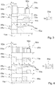
- FIG 1 shows a cooking device 30 designed as a hob 32.
- the cooking device 30 is designed as an induction hob 40.
- the cooking device 30 is designed as a classic induction hob 38 with four cooking zones 82. It is conceivable that the cooking device 30 is designed as a matrix hob.
- the cooking device 30 has a cooking device device 10.
- the cooking device device 10 is designed as an induction hob device.
- the cooking appliance device 10 has a base plate 42 for at least one cooking utensil 44.
- the set-up plate 42 is provided for setting up cookware 44.
- the set-up plate 42 is designed as a hob plate.
- the cooking device device 10 has a plurality of inductors 36.
- An inductor 36 is assigned to exactly one cooking zone 82. It is conceivable that in the case of a matrix hob, the inductors 36 are arranged in a matrix. The inductors 36 are each arranged under the respective cooking zone 82. Each inductor 36 has at least one induction coil. In the present exemplary embodiment, the cooking device device 10 has four inductors 36.
- the inductors 36 are arranged below the mounting plate 42.
- the inductors 36 are each intended to heat a cookware 44 placed on the base plate 42 above the inductors 36 in a continuous heating operating state.
- the cooking appliance device 10 has a control panel 34 for the input and / or selection of operating parameters by an operator, for example a target heating output 24 and / or a cooking time.
- the control panel 34 is designed as a display 46.
- the control panel 34 is provided for outputting a value of an operating parameter to the operator.
- the cooking device device 10 has a control unit 12.
- the control unit 12 is provided for carrying out actions and / or algorithms and / or changing settings as a function of operating parameters entered by an operator, such as for example a target heating output 24 and / or a cooking time.
- the control unit 12 defines induction targets 14, 50 based on the cookware 44 set up on the stand plate 42.
- two induction targets 14, 50 are defined by the control unit 12 based on the cookware 44 set up on the stand plate 42 and by the inductors 36, via which the cookware 44 are placed defined.
- An induction target 14, 50 has exactly one inductor 36.
- an induction target 14, 50 can have a plurality of inductors 36.
- An induction target 14, 50 has at least one cookware 44.
- the control unit 12 can define a plurality of induction targets 14, 50.
- An output heating power 48 of each induction target 14, 50 is significantly dependent on the heating frequency applied to the induction target 14, 50.
- the output heating power 48 of an induction target 14, 50 increases with a decreasing heating frequency.
- the output heating power 48 of an induction target 14, 50 drops with increasing heating frequency.
- the control unit 12 preferably operates the cooking device device 10 in the ZVS mode.
- an energy source supplies the induction targets 14, 50 with electrical energy.
- the energy source is an electrical current phase of a power supply network.
- the cooking appliance device 10a can have at least one inverter unit 70a for providing at least one heating frequency for the respective induction target 14a, 50a (cf. Figure 2 ).
- the control unit 12 is provided in the continuous heating mode for repetitive activation and power supply of the first induction target 14 and the second induction target 14 from the energy source.
- the control unit 12 is provided in the continuous heating operating state for the periodic activation and energy supply of the induction targets 14, 50.
- FIG 2 shows an embodiment of the cooking device 10a in a first embodiment with two induction targets 14a, 50a defined by a control unit 12a of the cooking device 10a.
- the control unit 12a defines a first and a second induction target 14a, 50a.
- the cooking appliance device 10a has a first and a second resonant inverter unit 70a, 84a.
- the inverter units 70a, 84a provide a heating frequency for the induction targets 14a, 50a.
- the inverter units 70a, 84a independently supply the induction targets 14a, 50a with electrical ones Energy.
- the first inverter unit 70a is assigned to the first induction target 14a.
- the second inverter unit 84a is assigned to the second induction target 50a.
- the cooking appliance device 10a has one electromechanical switch element 60a per one induction target 14a, 50a.
- the switch element 60a is designed as a relay 62a.
- the induction targets 14a, 50a can be connected to the electrical power supply by the relays 62a.
- the cooking appliance device 10a each has a resonance capacitor unit 28a per one induction target 14a, 50a. Each induction target 14a, 50a can be controlled individually with a respective heating frequency.
- control unit 12a In the continuous heating mode, the control unit 12a operates the induction targets 14a, 50a while avoiding intermodulation interference signals (cf. Fig. 3 ). In the continuous heating operating state, the control unit 12a sets output powers of the induction targets 14a, 50a via a respective heating frequency.
- the control unit 12a selects an activation sequence from a catalog of activation sequences in the continuous heating operating state. For example, in the continuous heating operating state to avoid intermodulation interference signals, the control unit 12a could operate the first induction target 14a and / or the second induction target 50a at least essentially with a substantially the same heating frequency.
- control unit 12a could operate the first induction target 14a and / or the second induction target 50a in the continuous heating operating state to avoid intermodulation interference signals with heating frequencies which differ by at least 17 kHz.
- control unit 12a could alternatively or additionally deactivate at least one of the induction targets 14a, 50a and operate at least one of the induction targets 14a, 50a with a specific heating frequency to avoid intermodulation interference signals.
- control unit 12a operates the induction targets 14a, 50a periodically over an entire cooking time.
- the cooking time is divided into operating periods 16a.
- the operating period 16a has three time intervals 18a t 1 , t 2 , t 3 (cf. Figure 3 ).
- control unit 12a operates the first induction target 14a in a first time interval 18a t 1 of the operating period 16a with a power surplus 20a compared to the target heating power 24a of the first induction target 14a.
- control unit 12a operates the first induction target 14a in a second time interval t 2 18a of the operating period 16a with a power deficit 22a compared to the target heating power 24a of the first induction target 14a.
- control unit 12a operates the first induction target 14a in a third time interval 18a t 3 of the operating period 16a with the target heating power 24a of the first induction target 14a.
- the control unit 12a operates the first induction target 14a in exactly one time interval 18a with an excess power 20a.
- the control unit 12a operates the first induction target 14a in exactly one time interval 18a with a power deficit 22a.
- control unit 12a operates the second induction target 50a in a first time interval 18a t 1 of the operating period 16a with the target heating power 24a of the second induction target 50a.
- the control unit 12a operates the second induction target 50a in a second time interval 18a t 2 of the operating period 16a with an excess power 20a compared to the target heating power 24a of the second induction target 50a.
- the control unit 12a operates the second induction target 50a in the third time interval 18a t 3 of the operating period 16a with a power deficit 22a compared to the target heating power 24a of the second induction target 50a.
- the control unit 12a operates the second induction target 50a in exactly one time interval 18a with an excess power 20a.
- the control unit 12a operates the second induction target 50a in exactly one time interval 18a with a power deficit 22a.
- control scheme 64a for two induction targets 14a, 50a has an operating period 16a with three time intervals 18a t 1 , t 2 , t 3 .
- the control unit 12a operates two induction targets 14a, 50a in three time intervals 18a t 1 , t 2 , t 3 .
- a number of the time intervals 18a is exactly 1 greater than a number of the induction targets 14a, 50a.
- Corresponding deviations from the output heating powers 48a of the induction targets 14a, 50a in the individual time intervals 18a from the target heating powers 24a are shown in the form of an S matrix 56a.
- the S matrix 56a contains characters + and -.
- the plus sign + stands for a surplus power 20a.
- the minus sign - stands for a performance deficit 22a.
- the output heating powers 48a, which correspond to the respective target heating powers 24a, are shown as zeros.
- the S matrix 56a gives that in Figure 3 shown control scheme 64a.
- the control unit 12a allows flicker to be controlled when the induction targets 14a, 50a are activated.
- a total output heating power 52a of the induction targets 14a, 50a lies above a total output target heating power 54a.
- the total output target heating power 54a is a sum of the target heating powers of the induction targets 14a, 50a.
- the total output heating power 52a of the induction targets 14a, 50a corresponds to the total output target heating power 54a.
- the total output heating power 52a of the induction targets 14a, 50a is below the total output target heating power 54a.
- a difference ⁇ P indicates a greatest difference between the total output heating powers 52a of time intervals 18a adjacent in time in a continuous continuous heating operating state. The greatest difference exists between the total output heating power 52a in the first time interval 18a t 1 and the total output heating power 52a in the last time interval 18a t 3 , since in the continuous continuous heating operating state the control scheme 64a repeats and thus the first time interval 18a t 1 the last time interval 18a t 3 will follow in a next operating period.
- the difference ⁇ P based on a duration of the operating period 16a determines a flicker parameter 26a.
- the control unit 12a keeps the flicker parameter 26a within an admissibility interval.
- the admissibility interval is regulated according to a flicker standard, in particular according to the DIN EN 61000-3-3 standard.
- FIG. 4 An exemplary representation of a control scheme 64a for three induction targets 14a, 50a, 66a is shown. The following description is essentially limited to the differences between the representations of the control diagrams 64a, whereby the features and functions that remain the same are described in the description of FIGS Figure 3 can be referred.
- the operating period 16a has four time intervals 18a t 1 , t 2 , t 3 , t 4 .
- the control unit 12a operates the first induction target 14a in a first time interval 18a t 1 with an excess power 20a.
- the control unit 12a operates the first induction target 14a in a second time interval 18a t 2 with a power deficit 22a.
- the Control unit 12a operates the first induction target 14a in a third and fourth time interval 18a t 3 , t 4 each with a target heating power 24a.
- the control unit 12a operates the second induction target 50a in a first and fourth time interval 18a t 1 , t 4 each with a target heating power 24a.
- the control unit 12a operates the second induction target 50a in a second time interval 18a t 2 with an excess power 20a.
- the control unit 12a operates the second induction target 50a in a third time interval 18a t 3 with a power deficit 22a.
- the control unit 12a operates the third induction target 66a in a first and second time interval 18a t 1 , t 2 each with a target heating power 24a.
- the control unit 12a operates the third induction target 66a in a third time interval 18a t 3 with an excess power 20a.
- the control unit 12a operates the third induction target 66a in a fourth time interval 18a t 4 with a power deficit 22a.
- Corresponding activation sequences 58a are shown in the form of an S matrix 56a.
- the S matrix 56a has exactly one power surplus 20a and exactly one power deficit 22a in each row.
- a number of columns of the S matrix 56a is 1 higher than a number of rows of the S matrix 56a.
- the number of columns of the S matrix 56a represents a number of the time intervals 18a.
- the number of rows of the S matrix 56a represents a number of the induction targets 14a, 50a, 66a.
- the control unit 12a allows flicker to be controlled when the induction targets 14a, 50a, 66a are activated.
- a total output heating power 52a of the induction targets 14a, 50a, 66a lies above a total output target heating power 54a.
- the total output target heating power 54a is a sum of the target heating powers 24a of the induction targets 14a, 50a, 66a.
- the total output heating power 52a of the induction targets 14a, 50a, 66a corresponds to the total output target heating power 54a.
- the total output heating power 52a of the induction targets 14a, 50a, 66a is below the total output target heating power 54a.
- a difference ⁇ P indicates a greatest difference between the total output heating powers 52a of adjacent time intervals 18a in the case of a continuous continuous heating operating state.
- the greatest difference is between the total output heating power 52a in the last time interval 18a t 4 and the total output heating power 52a in the first time interval 18a t 1 , since the control scheme is in the continuous continuous heating operating state 64a repeats itself and thus the first time interval 18a t 1 follows the last time interval 18a t 4 .
- the control unit 12a keeps the flicker parameter 26a within an admissibility interval.
- the admissibility interval is regulated according to a flicker standard, in particular according to the DIN EN 61000-3-3 standard.
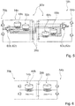
- FIG. 5 shows a further embodiment of the cooking device device 10b in a cost-effective embodiment with four induction targets 14b, 50b, 66b, 68b defined by a control unit 12b of the cooking device device 10b.
- the cooking appliance device 10b has a control unit 12b.
- the control unit 12b defines four induction targets 14b, 50b, 66b, 68b.
- the cooking appliance device 10b has two resonant inverter units 70b, 84b each with a half bridge 80b.
- the cooking appliance device 10b has six switch elements 60b.
- the switch elements 60b are designed as relays 62b.
- the control unit 12b controls the switch elements 60b as a function of a number of the induction targets 14b, 50b, 66b, 68b.
- the control unit 12b operates the induction targets 14b, 50b, 66b, 68b from different resonant inverter units 70b, 84b. In the event that three or more induction targets 14b, 50b, 66b, 68b are defined, the control unit 12b controls the switch elements 60b such that they switch at least one of the two resonant inverter units 70b, 84b between two induction targets 14b, 50b, 66b, 68b.
- induction targets 14b, 50b, 66b, 68b At least two induction targets 14b, 50b, 66b, 68b are connected to one of the two resonant inverter units 70b, 84b by the switch elements 60b. If there are three or more induction targets 14b, 50b, 66b, 68b, at least two induction targets 14b, 50b, 66b, 68b are connected to one of the two resonance capacitor units 28b.
- induction targets 14b, 50b, 66b, 68b defined by the control unit 12b are shown.
- Two induction targets 14b, 50b, 66b, 68b are connected to one of the resonant inverter units 70b, 84b by the switch elements 60b.
- Two induction targets 14b, 50b, 66b, 68b are connected to one of the resonance capacitor units 28b.
- Figure 6 shows two induction targets 14b, 50b in a simplified circuit diagram Figure 5 connected to a common resonance capacitor unit 28b.
- the induction targets 14b, 50b are connected to different resonant inverter units 70b, 84b.
- no switch elements 60b are shown.
- the control unit 12b changes into a special continuous heating operating state.
- the control unit 12b operates the induction targets 14b, 50b simultaneously.
- the control unit 12b operates both resonant inverter units 70b, 84b simultaneously.
- the control unit 12b controls output heating powers 48b of the induction targets 14b, 50b by means of control signals which are phase-shifted relative to one another in order to control the two induction targets 14b, 50b.
- a phase shift between the control signals can be implemented by controlling the resonant inverter units 70b, 84b by the control unit 12b.
- the control signals which are phase-shifted with respect to one another have the same heating frequency.
- Figure 7 shows an exemplary representation of a control scheme 64b for two induction targets 14b, 50b in the cost-effective embodiment of the cooking device device 10b.
- the control unit 12b operates the induction targets 14b, 50b during simultaneous operation with control signals of the same heating frequency which are phase-shifted with respect to one another.
- the operating period 16b has three time intervals 18b t 1 , t 2 , t 3 .
- the control unit 12b operates the first induction target 14b in a first time interval 18b t 1 with an excess power 20b.
- the control unit 12b operates the first induction target 14b in a second time interval 18b t 2 with a power deficit 22b.
- the control unit 12b operates the first induction target 14b in a third time interval 18b t 3 with a target heating power 24b.
- the control unit 12b operates the second induction target 50b in a first time interval 18b t 1 with a target heating power 24b.
- the control unit 12b operates the second induction target 50b in a second time interval 18b t 2 with an excess power 20b.
- the control unit 12b operates the second induction target 50b in a third time interval 18b t 3 with a power deficit 22b
- the control unit 12b operates the first and the second induction target 14b, 50b in the special continuous heating operating state with control signals of the same heating frequency f 1 .
- the control signals have a mutual phase shift ⁇ 1 .
- control unit 12b operates the first and the second induction target 14b, 50b in the special continuous heating operating state with control signals of the same heating frequency f 2 .
- the control signals have a mutual phase shift ⁇ 2 .
- Corresponding deviations from the output heating powers 48b of the induction targets 14b, 50bin in the individual time intervals 18b with respect to the target heating powers 24b are shown in the form of an S matrix 56b.
- the S matrix 56b has exactly one power surplus 20b and exactly one power deficit 22b in each row.
- a number of columns of the S matrix 56b is 1 higher than a number of rows of the S matrix 56b.
- the number of columns of the S matrix 56b represents a number of the time intervals 18b.
- the number of rows of the S matrix 56b represents a number of the induction targets 14b, 50b.
- the control unit 12b allows flicker to be controlled in the control of the induction targets 14b, 50b.
- a total output heating power 52b of the induction targets 14b, 50b lies above a total output target heating power 54b.
- the total output target heating power 54b is a sum of the target heating powers 24b of the induction targets 14b, 50b.
- the total output heating power 52b of the induction targets 14b, 50b corresponds to the total output target heating power 54b.
- the total output heating power 52b of the induction targets 14b, 50b is below the total output target heating power 54b (cf. Figure 7 ).
- a difference ⁇ P indicates a greatest difference between the total output heating powers 52b from adjacent time intervals 18b in the case of a continuous continuous heating operating state.
- the greatest difference is between the total output heating power 52b in the last time interval 18b t 3 and the total output heating power 52b in the first time interval 18b t 1 is present since, in the continuous continuous heating operating state, the control scheme 64b repeats and thus the first time interval 18b t 1 follows the last time interval 18b t 3 .
- the difference ⁇ P based on a duration of the operating period 16b determines a flicker parameter 26b.
- the control unit 12b keeps the flicker parameter 26b within an admissibility interval.
- the admissibility interval is regulated according to a flicker standard, in particular according to the DIN EN 61000-3-3 standard.
- Figure 8 shows an exemplary representation of a further control scheme 64b for two induction targets 14b, 50b in the cost-efficient embodiment of the cooking device device 10b.
- the control unit 12b operates the induction targets 14b, 50b during simultaneous operation with control signals of the same heating frequency which are phase-shifted with respect to one another.
- the operating period 16b has three time intervals 18b t 1 , t 2 , t 3 .
- the control unit 12b operates the first induction target 14b in a first time interval 18b t 1 with an excess power 20b.
- the control unit 12b operates the first induction target 14b in a second time interval 18b t 2 with a power deficit 22b.
- the control unit 12b operates the first induction target 14b in a third time interval 18b t 3 with a target heating power 24b.
- the control unit 12b operates the second induction target 50b in a first time interval 18b t 1 with a target heating power 24b.
- the control unit 12b operates the second induction target 50b in a second time interval 18b t 2 with an excess power 20b.
- the control unit 12b operates the second induction target 50b in a third time interval 18b t 3 with a power deficit 22b.
- the control unit 12b operates the first and the second induction target 14b, 50b with control signals of the same heating frequency f 1 with a mutual phase shift ⁇ 1 .
- Corresponding activation sequences 58b are shown in the form of an S matrix 56b.
- the S matrix 56b has exactly one power surplus 20b and exactly one power deficit 22b in each row.
- a number of columns of the S matrix 56b is 1 higher than a number of rows of the S matrix 56b.
- the number of columns of the S matrix 56b represents a number of the time intervals 18b.
- the number of rows of the S matrix 56b represents a number of the induction targets 14b, 50b.
- Figure 9 shows a method for operating the cooking device device 10.
- a number of induction targets 14, 50, 66, 68 are determined and a dimension of an S matrix 56 is determined.
- a number of rows of the S matrix 56 is equal to a number of the induction targets 14, 50, 66, 68.
- a number of columns of the S matrix 56 is 1 higher than a number of rows of the S matrix 56.
- the number of Columns of the S matrix 56 are equal to a number of time intervals 18 of an operating period 16.
- a control scheme 64 is sought, taking into account boundary conditions defined in the S matrix 56.
- the control scheme 64 has activation sequences 58.
- the activation sequences 58 have controls of the induction targets 14, 50, 66, 68 which are free of intermodulation interference signals from a catalog of activation sequences 58.
- Output heating powers 48 are summarized in a power matrix P when the control scheme 64 determined in the search step 74 is applied to the induction targets 14, 50, 66, 68.
- a number of rows n of the power matrix P is equal to a number of the induction targets 14, 50, 66, 68.
- a number of columns m of the power matrix P is equal to a number of time intervals 18. The number of columns m of the power matrix P is larger by 1 as the number of rows n of the power matrix P.
- a component P nm indicates an output power of an nth induction target in an mth time interval 18.
- a component P 11 indicates an output power of the first induction target 14 in the first time interval 18.
- a target heating power 24 requested by an operator for the induction targets 14, 50, 66, 68 is summarized.
- the target heating power vector b is a column vector of length n.
- An nth component b 1 of the target heating power vector b represents a target heating power 24 of an nth induction target 14 set by the operator.
- a second component b 2 of the target heating power vector b represents , for example, a target heating power 24 of the second induction target 50 set by the operator.
- the duration of the time intervals 18 are summarized in a duration vector x .
- the time duration vector x is a column vector of length m.
- An mth component x m of the time duration vector x represents the time duration of an mth time interval 18.
- a second component x 2 of the time duration vector x represents , for example, the time duration of the second time interval 18.
- the time duration vector x is unknown.
- the time duration vector x is calculated in the calculation step 76.
- the time periods of the time intervals 18 are calculated.
- the components of the duration vector x take non-negative values.
- the induction targets 14, 50, 66, 68 are operated in a continuous heating operating state in accordance with the control scheme 64, taking into account the time duration vector x .
Applications Claiming Priority (1)
| Application Number | Priority Date | Filing Date | Title |
|---|---|---|---|
| ES201831181A ES2764740A1 (es) | 2018-12-04 | 2018-12-04 | Dispositivo de aparato de cocción |
Publications (1)
| Publication Number | Publication Date |
|---|---|
| EP3664578A1 true EP3664578A1 (de) | 2020-06-10 |
Family
ID=68655409
Family Applications (1)
| Application Number | Title | Priority Date | Filing Date |
|---|---|---|---|
| EP19211263.9A Pending EP3664578A1 (de) | 2018-12-04 | 2019-11-25 | Gargerätevorrichtung |
Country Status (2)
| Country | Link |
|---|---|
| EP (1) | EP3664578A1 (es) |
| ES (1) | ES2764740A1 (es) |
Citations (6)
| Publication number | Priority date | Publication date | Assignee | Title |
|---|---|---|---|---|
| EP1951003A1 (en) * | 2007-01-23 | 2008-07-30 | Whirlpool Corporation | Control method for induction cooking hob and induction cooking hob adapted to carry out such method |
| DE102008042512A1 (de) * | 2008-09-30 | 2010-04-01 | BSH Bosch und Siemens Hausgeräte GmbH | Kochfeld und Verfahren zum Betreiben eines Kochfelds |
| US7910865B2 (en) | 2005-05-04 | 2011-03-22 | E.G.O. Elektro-Geraetebau Gmbh | Method and arrangement for supplying power to several induction coils in an induction apparatus |
| EP2469970A2 (de) * | 2010-12-27 | 2012-06-27 | BSH Bosch und Siemens Hausgeräte GmbH | Gargerätevorrichtung |
| WO2012131526A1 (de) * | 2011-03-30 | 2012-10-04 | BSH Bosch und Siemens Hausgeräte GmbH | Induktionsheizvorrichtung |
| EP2911472A2 (de) * | 2013-12-20 | 2015-08-26 | BSH Hausgeräte GmbH | Gargerätevorrichtung, insbesondere Kochfeldvorrichtung, mit einer Mehrzahl von Wechselrichtern |
Family Cites Families (1)
| Publication number | Priority date | Publication date | Assignee | Title |
|---|---|---|---|---|
| ES2564888B1 (es) * | 2014-09-24 | 2017-01-05 | BSH Electrodomésticos España S.A. | Dispositivo de aparato de cocción y procedimiento para la puesta en funcionamiento de un dispositivo de aparato de cocción |
-
2018
- 2018-12-04 ES ES201831181A patent/ES2764740A1/es not_active Withdrawn
-
2019
- 2019-11-25 EP EP19211263.9A patent/EP3664578A1/de active Pending
Patent Citations (7)
| Publication number | Priority date | Publication date | Assignee | Title |
|---|---|---|---|---|
| US7910865B2 (en) | 2005-05-04 | 2011-03-22 | E.G.O. Elektro-Geraetebau Gmbh | Method and arrangement for supplying power to several induction coils in an induction apparatus |
| EP1951003A1 (en) * | 2007-01-23 | 2008-07-30 | Whirlpool Corporation | Control method for induction cooking hob and induction cooking hob adapted to carry out such method |
| EP1951003B1 (en) | 2007-01-23 | 2009-12-09 | Whirlpool Corporation | Control method for induction cooking hob and induction cooking hob adapted to carry out such method |
| DE102008042512A1 (de) * | 2008-09-30 | 2010-04-01 | BSH Bosch und Siemens Hausgeräte GmbH | Kochfeld und Verfahren zum Betreiben eines Kochfelds |
| EP2469970A2 (de) * | 2010-12-27 | 2012-06-27 | BSH Bosch und Siemens Hausgeräte GmbH | Gargerätevorrichtung |
| WO2012131526A1 (de) * | 2011-03-30 | 2012-10-04 | BSH Bosch und Siemens Hausgeräte GmbH | Induktionsheizvorrichtung |
| EP2911472A2 (de) * | 2013-12-20 | 2015-08-26 | BSH Hausgeräte GmbH | Gargerätevorrichtung, insbesondere Kochfeldvorrichtung, mit einer Mehrzahl von Wechselrichtern |
Also Published As
| Publication number | Publication date |
|---|---|
| ES2764740A1 (es) | 2020-06-04 |
Similar Documents
| Publication | Publication Date | Title |
|---|---|---|
| EP2236004B1 (de) | Induktionskochfeld mit einer mehrzahl von induktionsheizkörpern | |
| EP2342943B1 (de) | Kochfeld und verfahren zum betreiben eines kochfelds | |
| EP1683257B1 (de) | Verfahren zur vermeidung bzw. reduktion von störschall in einer umrichterschaltung bei gleichzeitigem betrieb mehrerer ausgänge | |
| EP2586271B1 (de) | Kochmuldenvorrichtung | |
| WO2018116063A1 (de) | Gargerätevorrichtung und verfahren zum betrieb einer gargerätevorrichtung | |
| EP2469970B1 (de) | Gargerätevorrichtung | |
| EP2506663B1 (de) | Gargerätevorrichtung | |
| EP2506665A2 (de) | Gargerätevorrichtung | |
| EP2506666B1 (de) | Gargerätevorrichtung | |
| EP2911472B2 (de) | Gargerätevorrichtung, insbesondere Kochfeldvorrichtung, mit einer Mehrzahl von Wechselrichtern | |
| EP2469972B1 (de) | Gargerätevorrichtung sowie Verfahren zum Steuern der Gargerätevorrichtung bei dem eine Flickerkenngrösse iterativ verkleinert wird. | |
| EP3641497B1 (de) | Gargerätevorrichtung | |
| WO2020229336A1 (de) | Gargerätevorrichtung | |
| EP3664578A1 (de) | Gargerätevorrichtung | |
| EP3641494B1 (de) | Gargerätevorrichtung | |
| EP2469971B1 (de) | Gargerätevorrichtung | |
| DE102012201237A1 (de) | Hausgerätevorrichtung | |
| EP2506664B1 (de) | Gargerätevorrichtung | |
| EP2945461B1 (de) | Gargerätevorrichtung | |
| DE102019218792A1 (de) | Gargerätevorrichtung | |
| EP3484242A1 (de) | Induktionsgargerätevorrichtung | |
| DE102019215954A1 (de) | Gargerätevorrichtung | |
| EP2590475B1 (de) | Induktionsheizvorrichtung | |
| WO2020229335A1 (de) | Gargerätevorrichtung | |
| DE102019219622A1 (de) | Garofenvorrichtung |
Legal Events
| Date | Code | Title | Description |
|---|---|---|---|
| PUAI | Public reference made under article 153(3) epc to a published international application that has entered the european phase |
Free format text: ORIGINAL CODE: 0009012 |
|
| STAA | Information on the status of an ep patent application or granted ep patent |
Free format text: STATUS: THE APPLICATION HAS BEEN PUBLISHED |
|
| AK | Designated contracting states |
Kind code of ref document: A1 Designated state(s): AL AT BE BG CH CY CZ DE DK EE ES FI FR GB GR HR HU IE IS IT LI LT LU LV MC MK MT NL NO PL PT RO RS SE SI SK SM TR |
|
| AX | Request for extension of the european patent |
Extension state: BA ME |
|
| STAA | Information on the status of an ep patent application or granted ep patent |
Free format text: STATUS: REQUEST FOR EXAMINATION WAS MADE |
|
| 17P | Request for examination filed |
Effective date: 20201210 |
|
| RBV | Designated contracting states (corrected) |
Designated state(s): AL AT BE BG CH CY CZ DE DK EE ES FI FR GB GR HR HU IE IS IT LI LT LU LV MC MK MT NL NO PL PT RO RS SE SI SK SM TR |
|
| GRAP | Despatch of communication of intention to grant a patent |
Free format text: ORIGINAL CODE: EPIDOSNIGR1 |
|
| STAA | Information on the status of an ep patent application or granted ep patent |
Free format text: STATUS: GRANT OF PATENT IS INTENDED |
|
| INTG | Intention to grant announced |
Effective date: 20240202 |
|
| GRAS | Grant fee paid |
Free format text: ORIGINAL CODE: EPIDOSNIGR3 |