EP3664556A1 - Verfahren zur übertragung eines uplink-signals eines endgeräts in einem drahtloskommunikationssystem und endgerät mit verwendung des verfahrens - Google Patents
Verfahren zur übertragung eines uplink-signals eines endgeräts in einem drahtloskommunikationssystem und endgerät mit verwendung des verfahrens Download PDFInfo
- Publication number
- EP3664556A1 EP3664556A1 EP18841905.5A EP18841905A EP3664556A1 EP 3664556 A1 EP3664556 A1 EP 3664556A1 EP 18841905 A EP18841905 A EP 18841905A EP 3664556 A1 EP3664556 A1 EP 3664556A1
- Authority
- EP
- European Patent Office
- Prior art keywords
- transmission
- terminal
- resource set
- grant
- resource
- Prior art date
- Legal status (The legal status is an assumption and is not a legal conclusion. Google has not performed a legal analysis and makes no representation as to the accuracy of the status listed.)
- Granted
Links
Images


Classifications
-
- H—ELECTRICITY
- H04—ELECTRIC COMMUNICATION TECHNIQUE
- H04L—TRANSMISSION OF DIGITAL INFORMATION, e.g. TELEGRAPHIC COMMUNICATION
- H04L5/00—Arrangements affording multiple use of the transmission path
- H04L5/0091—Signalling for the administration of the divided path, e.g. signalling of configuration information
- H04L5/0096—Indication of changes in allocation
- H04L5/0098—Signalling of the activation or deactivation of component carriers, subcarriers or frequency bands
-
- H—ELECTRICITY
- H04—ELECTRIC COMMUNICATION TECHNIQUE
- H04W—WIRELESS COMMUNICATION NETWORKS
- H04W72/00—Local resource management
- H04W72/04—Wireless resource allocation
-
- H—ELECTRICITY
- H04—ELECTRIC COMMUNICATION TECHNIQUE
- H04L—TRANSMISSION OF DIGITAL INFORMATION, e.g. TELEGRAPHIC COMMUNICATION
- H04L1/00—Arrangements for detecting or preventing errors in the information received
- H04L1/004—Arrangements for detecting or preventing errors in the information received by using forward error control
- H04L1/0056—Systems characterized by the type of code used
- H04L1/0061—Error detection codes
-
- H—ELECTRICITY
- H04—ELECTRIC COMMUNICATION TECHNIQUE
- H04L—TRANSMISSION OF DIGITAL INFORMATION, e.g. TELEGRAPHIC COMMUNICATION
- H04L25/00—Baseband systems
- H04L25/02—Details ; arrangements for supplying electrical power along data transmission lines
- H04L25/0202—Channel estimation
- H04L25/0224—Channel estimation using sounding signals
- H04L25/0226—Channel estimation using sounding signals sounding signals per se
-
- H—ELECTRICITY
- H04—ELECTRIC COMMUNICATION TECHNIQUE
- H04L—TRANSMISSION OF DIGITAL INFORMATION, e.g. TELEGRAPHIC COMMUNICATION
- H04L5/00—Arrangements affording multiple use of the transmission path
- H04L5/003—Arrangements for allocating sub-channels of the transmission path
- H04L5/0048—Allocation of pilot signals, i.e. of signals known to the receiver
- H04L5/0051—Allocation of pilot signals, i.e. of signals known to the receiver of dedicated pilots, i.e. pilots destined for a single user or terminal
-
- H—ELECTRICITY
- H04—ELECTRIC COMMUNICATION TECHNIQUE
- H04W—WIRELESS COMMUNICATION NETWORKS
- H04W72/00—Local resource management
- H04W72/20—Control channels or signalling for resource management
- H04W72/21—Control channels or signalling for resource management in the uplink direction of a wireless link, i.e. towards the network
-
- H—ELECTRICITY
- H04—ELECTRIC COMMUNICATION TECHNIQUE
- H04W—WIRELESS COMMUNICATION NETWORKS
- H04W76/00—Connection management
- H04W76/10—Connection setup
- H04W76/11—Allocation or use of connection identifiers
-
- H—ELECTRICITY
- H04—ELECTRIC COMMUNICATION TECHNIQUE
- H04W—WIRELESS COMMUNICATION NETWORKS
- H04W76/00—Connection management
- H04W76/20—Manipulation of established connections
- H04W76/27—Transitions between radio resource control [RRC] states
-
- H—ELECTRICITY
- H04—ELECTRIC COMMUNICATION TECHNIQUE
- H04W—WIRELESS COMMUNICATION NETWORKS
- H04W72/00—Local resource management
- H04W72/20—Control channels or signalling for resource management
- H04W72/23—Control channels or signalling for resource management in the downlink direction of a wireless link, i.e. towards a terminal
Definitions
- the present disclosure relates to wireless communication and, more particularly, to a method for transmitting an uplink signal in a wireless communication system and a terminal using the same method.
- MTC massive machine type communications
- next generation radio access technology considering enhanced mobile broadband communication (eMBB), massive MTC (mMTC), ultrareliable and low latency communication (URLLC) is discussed.
- eMBB enhanced mobile broadband communication
- mMTC massive MTC
- URLLC ultrareliable and low latency communication
- This new technology may be called new radio access technology (new RAT or NR) in the present disclosure for convenience.
- the UE does not perform UL transmission without a grant when there is no uplink data to be actually transmitted. In this case, there may be a problem that it is ambiguous for the base station as to whether UL transmission is properly configured in the UE.
- a plurality of resource sets that can be used for UL transmission without grant may be configured, and activation/deactivation of grant-free UL transmission may be performed by one-time signaling.
- activation/deactivation of grant-free UL transmission may be performed by one-time signaling.
- RRC radio resource control
- the present disclosure provides a method for transmitting an uplink signal of a terminal in a wireless communication system, and a terminal using the same method.
- a method for transmitting an uplink (UL) signal of a terminal in a wireless communication system comprises receiving activation information for activating or deactivating a specific resource set from among a plurality of resource sets; and when the activation information activates the specific resource set, performing grant-free UL transmission using a resource belonging to the specific resource set.
- the activation information may be received through downlink control information (DCI).
- DCI downlink control information
- the activation information may comprise an identity (ID) of the specific resource set.
- the UL transmission may be a transmission of a physical uplink shared channel (PUSCH).
- PUSCH physical uplink shared channel
- the grant-free UL transmission may be transmitting, by the terminal, the PUSCH using any of resources belonging to the specific resource set without a UL grant for scheduling the PUSCH.
- a response to the activation information may be transmitted by the terminal.
- An acknowledgement to the activation information may be transmitted as the response.
- a sounding reference signal may be transmitted as the response.
- Channel state information may be transmitted as the response.
- a physical random access channel may be transmitted as the response.
- PRACH physical random access channel
- the plurality of resource sets may be configured by a radio resource control (RRC) signal.
- RRC radio resource control
- At least one resource set from among the plurality of resource sets may be used for a fallback operation in an RRC reconfiguration period.
- a physical layer signal indicating use of the at least one resource set may be further received.
- the activation information may use a scrambling or cyclic redundancy check (CRC) masking sequence specific to the specific resource set.
- CRC cyclic redundancy check
- a terminal comprising a transceiver configured to transmit and receive a radio signal; and a processor configured to operate with being connected to the transceiver, wherein the processor is further configured to receive activation information for activating or deactivating a specific resource set from among a plurality of resource sets, and, when the activation information activates the specific resource set, perform grant-free uplink (UL) transmission using a resource belonging to the specific resource set.
- a transceiver configured to transmit and receive a radio signal
- a processor configured to operate with being connected to the transceiver, wherein the processor is further configured to receive activation information for activating or deactivating a specific resource set from among a plurality of resource sets, and, when the activation information activates the specific resource set, perform grant-free uplink (UL) transmission using a resource belonging to the specific resource set.
- UL uplink
- a signal for setting (activating/deactivating) grant-free UL transmission indicates which resource set among resource sets that can be used for grant-free UL transmission, thereby reducing ambiguity as to a resource used for grant-free UL transmission.
- a resource set used for a fallback operation is introduced/used in an RRC reconfiguration period, thereby reducing ambiguity as to a resource set to be used in the RRC reconfiguration period.
- RRC radio resource control
- FIG. 1 shows a conventional wireless communication system.
- the wireless communication system may be referred to as an Evolved-UMTS Terrestrial Radio Access Network (E-UTRAN) or a Long Term Evolution (LTE)/LTE-A system.
- E-UTRAN Evolved-UMTS Terrestrial Radio Access Network
- LTE Long Term Evolution
- LTE-A Long Term Evolution
- the E-UTRAN includes at least one base station (BS) 20 which provides a control plane and a user plane to a user equipment (UE) 10.
- the UE 10 may be fixed or mobile, and may be referred to as another terminology, such as a mobile station (MS), a user terminal (UT), a subscriber station (SS), a mobile terminal (MT), a wireless device, etc.
- the BS 20 is generally a fixed station that communicates with the UE 10 and may be referred to as another terminology, such as an evolved node-B (eNB), a base transceiver system (BTS), an access point, etc.
- eNB evolved node-B
- BTS base transceiver system
- access point etc.
- the BSs 20 are interconnected by means of an X2 interface.
- the BSs 20 are also connected by means of an S1 interface to an evolved packet core (EPC) 30, more specifically, to a mobility management entity (MME) through S1-MME and to a serving gateway (S-GW) through S1-U.
- EPC evolved packet core
- MME mobility management entity
- S-GW serving gateway
- the EPC 30 includes an MME, an S-GW, and a packet data network-gateway (P-GW).
- the MME has access information of the UE or capability information of the UE, and such information is generally used for mobility management of the UE.
- the S-GW is a gateway having an E-UTRAN as an end point.
- the P-GW is a gateway having a PDN as an end point.
- Layers of a radio interface protocol between the UE and the network can be classified into a first layer (L1), a second layer (L2), and a third layer (L3) based on the lower three layers of the open system interconnection (OSI) model that is well-known in the communication system.
- a physical (PHY) layer belonging to the first layer provides an information transfer service by using a physical channel
- a radio resource control (RRC) layer belonging to the third layer serves to control a radio resource between the UE and the network.
- the RRC layer exchanges an RRC message between the UE and the BS.
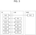
- FIG. 2 is a diagram showing a wireless protocol architecture for a user plane.
- FIG. 3 is a diagram showing a wireless protocol architecture for a control plane.
- the user plane is a protocol stack for user data transmission.
- the control plane is a protocol stack for control signal transmission.
- a PHY layer provides an upper layer with an information transfer service through a physical channel.
- the PHY layer is connected to a medium access control (MAC) layer which is an upper layer of the PHY layer through a transport channel.
- MAC medium access control
- Data is transferred between the MAC layer and the PHY layer through the transport channel.
- the transport channel is classified according to how and with what characteristics data is transferred through a radio interface.
- the physical channel may be modulated according to an Orthogonal Frequency Division Multiplexing (OFDM) scheme, and use the time and frequency as radio resources.
- OFDM Orthogonal Frequency Division Multiplexing
- the functions of the MAC layer include mapping between a logical channel and a transport channel and multiplexing and demultiplexing to a transport block that is provided through a physical channel on the transport channel of a MAC Service Data Unit (SDU) that belongs to a logical channel.
- SDU MAC Service Data Unit
- the MAC layer provides service to a Radio Link Control (RLC) layer through the logical channel.
- RLC Radio Link Control
- the functions of the RLC layer include the concatenation, segmentation, and reassembly of an RLC SDU.
- QoS Quality of Service
- RB Radio Bearer
- the RLC layer provides three types of operation mode: Transparent Mode (TM), Unacknowledged Mode (UM), and Acknowledged Mode (AM).
- TM Transparent Mode
- UM Unacknowledged Mode
- AM Acknowledged Mode
- AM RLC provides error correction through an Automatic Repeat Request (ARQ).
- ARQ Automatic Repeat Request
- the RRC layer is defined only on the control plane.
- the RRC layer is related to the configuration, reconfiguration, and release of radio bearers, and is responsible for control of logical channels, transport channels, and PHY channels.
- An RB means a logical route that is provided by the first layer (PHY layer) and the second layers (MAC layer, the RLC layer, and the PDCP layer) in order to transfer data between UE and a network.
- the function of a Packet Data Convergence Protocol (PDCP) layer on the user plane includes the transfer of user data and header compression and ciphering.
- the function of the PDCP layer on the user plane further includes the transfer and encryption/integrity protection of control plane data.
- PDCP Packet Data Convergence Protocol
- What an RB is configured means a process of defining the characteristics of a wireless protocol layer and channels in order to provide specific service and configuring each detailed parameter and operating method.
- An RB can be divided into two types of a Signaling RB (SRB) and a Data RB (DRB).
- SRB Signaling RB
- DRB Data RB
- the SRB is used as a passage through which an RRC message is transmitted on the control plane
- the DRB is used as a passage through which user data is transmitted on the user plane.
- the UE If RRC connection is established between the RRC layer of UE and the RRC layer of an E-UTRAN, the UE is in the RRC connected state. If not, the UE is in the RRC idle state.
- a downlink transport channel through which data is transmitted from a network to UE includes a broadcast channel (BCH) through which system information is transmitted and a downlink shared channel (SCH) through which user traffic or control messages are transmitted. Traffic or a control message for downlink multicast or broadcast service may be transmitted through the downlink SCH, or may be transmitted through an additional downlink multicast channel (MCH).
- BCH broadcast channel
- SCH downlink shared channel
- Traffic or a control message for downlink multicast or broadcast service may be transmitted through the downlink SCH, or may be transmitted through an additional downlink multicast channel (MCH).
- MCH downlink multicast channel
- an uplink transport channel through which data is transmitted from UE to a network includes a random access channel (RACH) through which an initial control message is transmitted and an uplink shared channel (SCH) through which user traffic or control messages are transmitted.
- RACH random access channel
- SCH uplink shared channel
- Logical channels that are placed over the transport channel and that are mapped to the transport channel include a broadcast control channel (BCCH), a paging control channel (PCCH), a common control channel (CCCH), a multicast control channel (MCCH), and a multicast traffic channel (MTCH).
- BCCH broadcast control channel
- PCCH paging control channel
- CCCH common control channel
- MCCH multicast control channel
- MTCH multicast traffic channel
- the physical channel includes several OFDM symbols in the time domain and several subcarriers in the frequency domain.
- One subframe includes a plurality of OFDM symbols in the time domain.
- An RB is a resources allocation unit, and includes a plurality of OFDM symbols and a plurality of subcarriers.
- each subframe may use specific subcarriers of specific OFDM symbols (e.g., the first OFDM symbol) of the corresponding subframe for a physical downlink control channel (PDCCH), that is, an L1/L2 control channel.
- PDCCH physical downlink control channel
- a Transmission Time Interval (TTI) is a unit time for subframe transmission.
- new radio access technology new RAT, NR
- next generation radio access technology considering enhanced mobile broadband communication (eMBB), massive MTC (mMTC), ultrareliable and low latency communication (URLLC) is discussed.
- eMBB enhanced mobile broadband communication
- mMTC massive MTC
- URLLC ultrareliable and low latency communication
- This new technology may be called new radio access technology (new RAT or NR) in the present disclosure for convenience.
- FIG. 4 illustrates a system structure of a next generation radio access network (NG-RAN) to which NR is applied.
- NG-RAN next generation radio access network
- the NG-RAN may include a gNB and/or an eNB that provides user plane and control plane protocol termination to a terminal.
- FIG. 4 illustrates the case of including only gNBs.
- the gNB and the eNB are connected by an Xn interface.
- the gNB and the eNB are connected to a 5G core network (5GC) via an NG interface.
- 5GC 5G core network
- the gNB and the eNB are connected to an access and mobility management function (AMF) via an NG-C interface and connected to a user plane function (UPF) via an NG-U interface.
- AMF access and mobility management function
- UPF user plane function
- the gNB may provide functions of inter-cell radio resource management (Inter Cell RRM), radio bearer management (RB control), connection mobility control, radio admission control, and measurement setup and provision, dynamic resource allocation, and the like.
- the AMF may provide functions such as NAS security, idle state mobility handling, and the like.
- the UPF may provide functions such as mobility anchoring, PDU processing, and the like.
- FIG. 5 illustrates an example of a frame structure that may be applied in NR
- a frame may be composed of 10 milliseconds (ms) and include 10 subframes each composed of 1 ms.
- One or a plurality of slots may be included in a subframe according to subcarrier spacings.
- the following table 2 illustrates the number of slots in a frame (N frame, ⁇ slot ), the number of slots in a subframe (N subframe, ⁇ slot ), the number of symbols in a slot (N slot symb ), and the like, according to subcarrier spacing configurations ⁇ .
- [Table 2] ⁇ N symb slot N slot frame , ⁇ N slot subframe , ⁇ 0 14 10 1 1 14 20 2 2 14 40 4 3 14 80 8 4 14 160 16
- a slot may include a plurality of orthogonal frequency division multiplexing (OFDM) symbols.
- the plurality of OFDM symbols in the slot may be divided into downlink symbols (denoted as D), flexible symbols (denoted as X), and uplink symbols (denoted as U).
- the format of the slot may be determined according to which of the D, X, and U are configured in the slot as the OFDM symbols.
- the terminal may be configured with the format of the slot through a higher layer signal, the format of the slot through DCI, or the format of the slot based on a combination of the higher layer signal and the DCI.
- a physical downlink control channel may include one or more control channel elements (CCEs) as illustrated in the following table.
- CCEs control channel elements
- the PDCCH may be transmitted through a resource including 1, 2, 4, 8, or 16 CCEs.
- the CCE includes six resource element groups (REGs), and one REG includes one resource block in a frequency domain and one orthogonal frequency division multiplexing (OFDM) symbol in a time domain.
- REGs resource element groups
- OFDM orthogonal frequency division multiplexing
- the terminal may receive the PDCCH in the CORESET.
- FIG. 6 illustrates CORESET
- the CORESET includes N CORESET RB number of resource blocks in the frequency domain, and N CORESET symb ⁇ ⁇ 1, 2, 3 ⁇ number of symbols in the time domain.
- N CORESET RB and N CORESET symb may be provided by a base station via higher layer signaling.
- a plurality of CCEs (or REGs) may be included in the CORESET.
- the UE may attempt to detect a PDCCH in units of 1, 2, 4, 8, or 16 CCEs in the CORESET.
- PDCCH candidates One or a plurality of CCEs in which PDCCH detection may be attempted may be referred to as PDCCH candidates.
- a plurality of CORESETs may be configured for the terminal.
- FIG. 7 is a diagram illustrating a difference between a related art control region and the CORESET in NR
- a control region 300 in the related art wireless communication system (e.g., LTE/LTE-A) is configured over the entire system band used by a base station (BS). All the terminals, excluding some (e.g., eMTC/NB-IoT terminal) supporting only a narrow band, must be able to receive wireless signals of the entire system band of the BS in order to properly receive/decode control information transmitted by the BS.
- BS base station
- CORESETs 301, 302, and 303 are radio resources for control information to be received by the terminal and may use only a portion, rather than the entirety of the system bandwidth.
- the BS may allocate the CORESET to each UE and may transmit control information through the allocated CORESET. For example, in FIG. 6 , a first CORESET 301 may be allocated to UE 1, a second CORESET 302 may be allocated to UE 2, and a third CORESET 303 may be allocated to UE 3.
- the terminal may receive control information from the BS, without necessarily receiving the entire system band.
- the CORESET may include a UE-specific CORESET for transmitting UE-specific control information and a common CORESET for transmitting control information common to all UEs.
- FIG. 8 illustrates a carrier bandwidth part that has been newly introduced in NR
- the carrier bandwidth part may be simply abbreviated as a bandwidth part (BWP).
- BWP bandwidth part
- various numerologies e.g., various subcarrier spacings
- NR may define a common resource block (CRB) for a given numerology on a given carrier.
- CRB common resource block
- the bandwidth part is a set of contiguous physical resource blocks (PRBs) selected from contiguous subsets of common resource blocks (CRBs) for a given numerology on a given carrier.
- PRBs physical resource blocks
- CRBs common resource blocks
- a common resource block may be determined according to a numerology for which carrier bandwidth, for example, a subcarrier spacing, is used.
- the common resource block may be indexed from the lowest frequency of the carrier bandwidth (starting from 0), and a resource grid based on the common resource block may be defined (referred to as a common resource block resource grid).
- the bandwidth part may be indicated based on a CRB having the lowest index (referred to as CRB 0).
- CRB 0 The CRB 0 having the lowest index may be also referred to as point A.
- i-th bandwidth part may be indicated by NstartBWP,i and NsizeBWP,i.
- NstartBWP,i may indicate a start CRB of the i-th BWP on the basis of CRB
- NsizeBWP,i may indicate the size of the i-th bandwidth in the frequency domain (for example, based on a PRB unit).
- PRBs in each BWP may be indexed from 0.
- the index of the CRB in each BWP may be mapped to the index of the PRB.
- a terminal may be configured with up to four downlink bandwidth parts in downlink, but only one downlink bandwidth part may be activated at a given time point. The terminal does not expect to receive a PDSCH, a PDCCH, a CSI-RS, etc. out of the downlink bandwidth part activated among the downlink bandwidth parts.
- Each downlink bandwidth part may include at least one CORESET.
- the terminal may be configured with up to four uplink bandwidth parts in uplink, but only one uplink bandwidth part may be activated at a given time point.
- the terminal does not transmit a PUSCH, a PUCCH, etc. out of the uplink bandwidth part activated among the uplink bandwidth parts.
- the bandwidth part may have a feature of enabling a terminal incapable of supporting the broadband to operate.
- FIG. 9 illustrates an example of a frame structure for new radio access technology.
- a structure in which a control channel and a data channel are time-division-multiplexed within one TTI, as shown in FIG. 9 can be considered as a frame structure in order to minimize latency.
- a shaded region represents a downlink control region and a black region represents an uplink control region.
- the remaining region may be used for downlink (DL) data transmission or uplink (UL) data transmission.
- DL transmission and UL transmission are sequentially performed within one subframe and thus DL data can be transmitted and UL ACK/NACK can be received within the subframe. Consequently, a time required from occurrence of a data transmission error to data retransmission is reduced, thereby minimizing latency in final data transmission.
- a time gap for a base station and a terminal to switch from a transmission mode to a reception mode or from the reception mode to the transmission mode may be required.
- some OFDM symbols at a time when DL switches to UL may be set to a guard period (GP) in the self-contained subframe structure.
- Wavelengths are shortened in millimeter wave (mmW) and thus a large number of antenna elements can be installed in the same area. That is, the wavelength is 1 cm at 30 GHz and thus a total of 100 antenna elements can be installed in the form of a 2-dimensional array at an interval of 0.5 lambda (wavelength) in a panel of 4 ⁇ 4 cm. Accordingly, it is possible to increase a beamforming (BF) gain using a large number of antenna elements to increase coverage or improve throughput in mmW.
- BF beamforming
- TXRU transceiver unit
- independent beamforming per frequency resource can be performed.
- installation of TXRUs for all of about 100 antenna elements decreases effectiveness in terms of cost. Accordingly, a method of mapping a large number of antenna elements to one TXRU and controlling a beam direction using an analog phase shifter is considered.
- Such analog beamforming can form only one beam direction in all bands and thus cannot provide frequency selective beamforming.
- Hybrid beamforming (BF) having a number B of TXRUs which is smaller than Q antenna elements can be considered as an intermediate form of digital BF and analog BF.
- the number of directions of beams which can be simultaneously transmitted are limited to B although it depends on a method of connecting the B TXRUs and the Q antenna elements.
- FIG. 10 illustrates an existing UL transmission method.
- a terminal receives an UL grant at a time point T1 and transmits UL data at a time point T2.
- At least one of a time resource and a frequency resource used for the UL data transmission may be indicated by the UL grant, which may be also expressed as the UL data transmission is scheduled by the UL grant.
- the time points T1 and T2 may be predetermined, the time point T2 may be indicated by the UL grant, or the time point T2 may be determined dependently on the time point T1.
- the present disclosure relates to uplink grant-free UL transmission.
- a physical layer (L1) signaling method for efficiently operating when (re)configuring a resource for grant-free UL transmission (UL transmission), and an operating method during an RRC reconfiguration period are proposed.
- the introduction of a method of greatly reducing transmission latency depending on the application field is considered.
- introduction of a method in which UL transmission is started by determination of a terminal (the method which can be referred to as a grant-free UL transmission since UL transmission is started without a UL grant) is considered.
- the base station may set a resource set for grant-free UL transmission and may instruct or inform the terminal of the resource set.
- the terminal may start UL transmission even without a UL grant.
- Resources for grant-free UL transmission may be configured through RRC configuration and/or physical layer (L1) signaling.
- the present disclosure proposes a method for reducing ambiguity when configuring resources for grant-free UL transmission.
- information indicated by the base station, an operation of the base station, an operation of the terminal, or information indicated by the terminal are merely examples, and it is obvious that the idea of the present disclosure may be extended and applied to a reverse situation (that is, in which the roles of the base station and the terminal are reversed) or a situation a situation of being replaced with another node.
- a reverse situation that is, in which the roles of the base station and the terminal are reversed
- a situation a situation of being replaced with another node may be extended and applied even to downlink transmission, sidelink transmission, and the like.
- a resource for grant-free UL transmission (hereinafter, referred to as a GF resource) may be a resource after L1 signaling is transmitted.
- the L1 signaling may indicate at least a frequency resource for grant-free UL transmission.
- timing information on 1) downlink control signals and downlink data and/or 2) uplink grant and uplink data may be set semi-statically or dynamically indicated in DCI.
- a time point at which the resource starts may be set based on timing information in L1 signaling and L1 signaling.
- timing information (a specific value and/or a range of values and/or whether it is semi-statically or dynamically changeable) may be set independently of grant-free UL transmission.
- timing information may be different depending on the setting.
- a grant-free UL transmission resource (GF resource) may be set from slots corresponding to timing information indicated by an L1 signal. If semi-static timing is applied, it may be set based on UL grant-to-UL data timing. The above scheme may be applied to activation and/or deactivation and/or modification.
- the terminal does not always need to transmit a PUSCH in a resource for grant-free UL transmission (GF resources) and may transmit the PUSCH only when there is at least UL traffic. That is, the UE does not transmit the PUSCH in the GF resource, for example, 1) when an L1 signal for configuring the GF resource is properly detected but there is no UL traffic, or 2) when (there is UL traffic) the L1 signal for configuring the GF resource is not properly detected.
- GF resources grant-free UL transmission
- the fact that the terminal has not transmitted the PUSCH in the GF resource is not enough to allow the base station to know whether or not the terminal has not detected the L1 signal for configuring the GF resource, and thus, there may be ambiguity between the terminal and the base station.
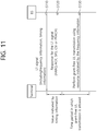
- FIG. 11 illustrates an example of signaling between a terminal and a base station for a grant-free UL transmission operation.
- the base station transmits an L1 signal (physical layer signal) for configuring grant-free UL transmission in a terminal (e.g., activation/deactivation of grant-free UL transmission and configuration of a resource/resource set for performing grant-free UL transmission) (S110).
- the L1 signal may include, for example, frequency information indicating a frequency available to be used for grant-free UL transmission and timing information indicating a time when grant-free UL transmission is allowed/supported.
- the terminal transmits a response to the L1 signal to the base station (S120). That is, in the present disclosure, the terminal may send a response signal to the L1 signal.
- Embodiment 1 The terminal may perform HARQ-ACK feedback with respect to the L1 signal for activation and/or deactivation.
- the timing of the HARQ-ACK feedback may be after a specific time point from when the corresponding L1 signal is received.
- the specific time point may be the same as a UL grant-to-UL data timing or may be a timing difference between resources for an L1 signal for grant-free UL transmission. If the timing is dynamically indicated by the L1 signal, the timing may be changed according to the indication.
- Embodiment 2 A sounding reference signal (SRS) request field may exist in the L1 signal for activation and/or deactivation.
- the SRS may be used as a response signal to the L1 signal.
- a time point at which the SRS is transmitted may be the first resource indicated through the L1 signal.
- the SRS may be transmitted after a certain period of time (or predefined or signaled by a higher layer and/or set by a dynamic indication) from a time point when the L1 signal is received.
- Embodiment 3 A CSI request field may exist in the L1 signal for activation and/or deactivation.
- the CSI may be used as a response signal to the L1 signal.
- UL data may or may not be transmitted from the first resource, and thus, the same location and method of mapping CSI with or without UL data may be used to avoid ambiguity.
- Embodiment 4 When the terminal receives an L1 signal for activation and/or deactivation, the terminal may transmit a PRACH in response thereto.
- the above scheme may have an advantage when it comes to adjusting UL synch in advance in starting grant-free UL transmission. More specifically, whether to transmit the PRACH may be indicated by the L1 signal.
- grant-free UL transmission may be possible after a time point indicated by the timing information (or during a time period) based on the time point at which the L1 signal is received.
- grant-free UL transmission In a time period in which grant-free UL transmission is possible, the terminal performs grant-free UL transmission to the base station (S130). At this point, grant-free UL transmission may be performed using a resource indicated by the frequency information.
- FIG. 12 illustrates a method of performing grant-free UL transmission.
- the terminal receives activation information for activating or deactivating a specific resource set from a plurality of resource sets (S210), and, when the activation information activates a resource set, grant-free UL transmission is performed using a resource belonging to the specific resource set (S220).
- the activation information may be received through downlink control information (DCI).
- the activation information may include an identity (ID) of the specific resource set.
- the UL transmission may be a physical uplink shared channel (PUSCH) transmission, and the grant-free UL transmission may indicate that the terminal transmits the PUSCH using any resource from among resources belonging to the specific resource set without an uplink grant for scheduling the PUSCH.
- PUSCH physical uplink shared channel
- a plurality of resource sets for grant-free UL transmission may be configured.
- the base station may configure a resource set for UL transmission for UL SPS and latency reduction, and, even for the latency reduction purpose, various resource sets may be set according to the amount or characteristics of traffic.
- each resource set is to be configured based on an RRC configuration without an L1 signal or based on the L1 signal may be designated for each resource set. Then, it may be advantageous especially when an application of grant-free UL transmission is different.
- whether a resource set is to be configured based on an RRC configuring method without an L1 signal or based on the L1 signal may be set UE-specifically. In this case, whether to use or not the resource set may be determined according to the reliability of the L1 signal.
- the payload size of the signal may be excessively large.
- overhead may be reduced by setting candidate parameters for the plurality of resource sets through an RRC signal and selecting one of the candidates through an L1 signal.
- an L1 signal for activation or deactivation of each resource set may be supported.
- the L1 signal may include information indicating a resource set ID or which grant-free UL transmission in the corresponding DCI.
- the L1 signal for activation or deactivation of each resource set may have different data scrambles and/or cyclic redundancy check (CRC) masking sequences.
- CRC cyclic redundancy check
- FIG. 13 illustrates an example of an operation of a terminal when a plurality of resource sets for grant-free UL transmission is configured.
- the terminal may receive configuration information for configuring a plurality of resource sets for grant-free UL transmission, for example, a first resource set and a second resource set.
- the configuration information may be transmitted by the base station using the RRC signal or an L1 signal.
- the terminal may receive a signal for activating (or deactivating, and activating is herein described as an example) a specific resource set, for example, a first resource set, from among the plurality of resource sets.
- the activation signal may be an L1 signal and may include information indicating the specific resource set, for example, an ID of the specific resource set.
- the terminal may perform grant-free UL transmission through any resource determined by the selection of the terminal from among resources belonging to the first resource set.
- a resource set may be configured in the form of RRC configuration before UL traffic occurs.
- RRC configuration since the amount or characteristic of traffic changes as time passes, it may be necessary to change a resource set, and the change may be performed through an RRC reconfiguration process.
- gNB base station
- at least a resource set to be used for the fallback operation in setting a resource set for grant-free UL transmission may be configured.
- the base station may need to instruct the UE whether to use the resource set.
- the base station may instruct the terminal through an L1 signal (e.g., PDCCH and/or PDSCH) to perform grant-free UL transmission using a specific resource set for a fallback operation.
- the base station may instruct the terminal through a media access (MAC) message to perform the grant-free UL transmission using a specific resource set (for a fallback operation).
- MAC media access
- FIG. 14 illustrates another example of an uplink signal transmission method of a terminal in a wireless communication system.
- a base station transmits an RRC configuration to a terminal (S310).
- the RRC configuration may include, for example, information for configuring a first resource set for grant-free UL transmission and a fallback resource set for a fallback operation.
- the terminal may perform grant-free UL transmission using resources in the first resource set (S320).
- an amount or characteristics of traffic of the terminal may be changed (S330).
- the terminal may request the RRC reconfiguration to the base station (S340).
- the base station first transmits an L1 signal or a media access control (MAC) message indicating "grant-free UL transmission" using the fallback resource set to the terminal (S350). Then, the terminal performs grant-free UL transmission using the fallback resource set in the RRC reconfiguration period (S360).
- MAC media access control
- the base station transmits an RRC reconfiguration message to the terminal (S370).
- the RRC reconfiguration message may set/indicate a second resource set for grant-free UL transmission.
- the terminal performs grant-free transmission using resources in the second resource set (S380).
- the second resource set may be resources determined in consideration of the changed amount/characteristic of the terminal traffic, and thus, the grant-free UL transmission of the terminal may be more efficient.
- FIG. 15 is a block diagram of an apparatus in which an embodiment of the present disclosure is implemented.
- an apparatus 100 includes a processor 110, a memory 120, and a transceiver 130.
- the processor 110 implements the proposed functions, processes, and/or methods.
- the memory 120 is connected to the processor 110 and stores various types of information for driving the processor 110.
- the transceiver 130 is connected to the processor 110 to transmit and/or receive a radio signal.
- the device 100 may be a base station or a terminal.
- the processor 110 may include an application-specific integrated circuit (ASIC), a different chipset, a logic circuit, a data processing device, and/or a converter for converting baseband signals and radio signals to and from each other.
- the memory 120 may include a read-only memory (ROM), a random access memory (RAM), a flash memory, a memory card, a storage medium, and/or any other storage device.
- the transceiver 130 may include one or more antennas for transmitting and/or receiving radio signals.
- the above-described technique may be implemented as a module (a process, a function, etc.) for performing the above-described function.
- the module may be stored in the memory 120 and executed by the processor 110.
- the memory 120 may be provided inside or outside the processor 110 and may be connected to the processor 110 using any of various well-known means.
Landscapes
- Engineering & Computer Science (AREA)
- Signal Processing (AREA)
- Computer Networks & Wireless Communication (AREA)
- Power Engineering (AREA)
- Mobile Radio Communication Systems (AREA)
Applications Claiming Priority (2)
| Application Number | Priority Date | Filing Date | Title |
|---|---|---|---|
| US201762540552P | 2017-08-02 | 2017-08-02 | |
| PCT/KR2018/008740 WO2019027251A1 (ko) | 2017-08-02 | 2018-08-01 | 무선 통신 시스템에서 단말의 상향링크 신호 전송 방법 및 상기 방법을 이용하는 단말 |
Publications (3)
| Publication Number | Publication Date |
|---|---|
| EP3664556A1 true EP3664556A1 (de) | 2020-06-10 |
| EP3664556A4 EP3664556A4 (de) | 2021-03-10 |
| EP3664556B1 EP3664556B1 (de) | 2024-10-02 |
Family
ID=65232919
Family Applications (1)
| Application Number | Title | Priority Date | Filing Date |
|---|---|---|---|
| EP18841905.5A Active EP3664556B1 (de) | 2017-08-02 | 2018-08-01 | Verfahren zur übertragung eines uplink-signals eines endgeräts in einem drahtloskommunikationssystem und endgerät mit verwendung des verfahrens |
Country Status (4)
| Country | Link |
|---|---|
| US (1) | US11310018B2 (de) |
| EP (1) | EP3664556B1 (de) |
| CN (1) | CN111034321B (de) |
| WO (1) | WO2019027251A1 (de) |
Families Citing this family (3)
| Publication number | Priority date | Publication date | Assignee | Title |
|---|---|---|---|---|
| CN111278172B (zh) * | 2019-03-27 | 2022-08-02 | 维沃移动通信有限公司 | 指示方法、终端设备和网络侧设备 |
| US11483862B2 (en) * | 2019-07-02 | 2022-10-25 | Qualcomm Incorporated | Configured grant resource validation |
| CN113079570B (zh) * | 2020-01-03 | 2023-06-30 | 大唐移动通信设备有限公司 | 传输方法及设备 |
Family Cites Families (10)
| Publication number | Priority date | Publication date | Assignee | Title |
|---|---|---|---|---|
| WO2013015637A2 (ko) * | 2011-07-26 | 2013-01-31 | 엘지전자 주식회사 | 상향링크 신호 전송방법 및 사용자기기, 상향링크 신호 수신방법 및 기지국 |
| US9516658B2 (en) * | 2012-08-02 | 2016-12-06 | Lg Electronics Inc. | Method for transmitting and receiving uplink signal on basis of interference measurement in base station cooperative wireless communication system and device for same |
| WO2015119465A1 (ko) * | 2014-02-08 | 2015-08-13 | 엘지전자 주식회사 | 무선 자원의 용도 변경을 지원하는 무선 통신 시스템에서 폴백(fallback) 모드의 상향링크 신호 송신 방법 및 이를 위한 장치 |
| CN107409413B (zh) * | 2015-04-15 | 2021-06-04 | 苹果公司 | 蜂窝网络中用于机器类型通信的方法和装置 |
| WO2017038337A1 (ja) * | 2015-08-31 | 2017-03-09 | 京セラ株式会社 | 無線端末及び基地局 |
| WO2017039564A1 (en) | 2015-09-04 | 2017-03-09 | Intel Corporation | Grant-less pusch uplink |
| US20180035459A1 (en) * | 2016-07-29 | 2018-02-01 | Huawei Technologies Co., Ltd. | Coexistence of Grant-Based and Grant-Free Uplink Transmissions in a Channel |
| WO2018031620A1 (en) * | 2016-08-12 | 2018-02-15 | Intel IP Corporation | Uplink grant-free noma (non-orthogonal multiple access) transmissions |
| CN116209048A (zh) * | 2017-03-22 | 2023-06-02 | Idac控股公司 | 用于在新型无线电(nr)系统中执行功率控制的方法 |
| US11122612B2 (en) * | 2017-06-15 | 2021-09-14 | Samsung Electronics Co., Ltd. | Logical channel mapping to grant free transmission |
-
2018
- 2018-08-01 EP EP18841905.5A patent/EP3664556B1/de active Active
- 2018-08-01 CN CN201880052578.8A patent/CN111034321B/zh active Active
- 2018-08-01 WO PCT/KR2018/008740 patent/WO2019027251A1/ko not_active Ceased
- 2018-08-01 US US16/635,114 patent/US11310018B2/en active Active
Also Published As
| Publication number | Publication date |
|---|---|
| US20200252190A1 (en) | 2020-08-06 |
| EP3664556A4 (de) | 2021-03-10 |
| EP3664556B1 (de) | 2024-10-02 |
| CN111034321B (zh) | 2023-08-25 |
| US11310018B2 (en) | 2022-04-19 |
| WO2019027251A1 (ko) | 2019-02-07 |
| CN111034321A (zh) | 2020-04-17 |
Similar Documents
| Publication | Publication Date | Title |
|---|---|---|
| US11477791B2 (en) | Resource allocation-related signaling method in wireless communication system and device using same | |
| EP3637911B1 (de) | Von endgerät in einem drahtloskommunikationssystem durchgeführtes verfahren zum empfangen eines downlink-steuerungskanals und endgerät mit verwendung davon | |
| EP3968719B1 (de) | Verfahren zur zuteilung von ressourcen in einem drahtlosen kommunikationssystem und vorrichtung damit | |
| US11363628B2 (en) | Method and apparatus for performing uplink transmission with pre-allocated beams in wireless communication system | |
| US12075421B2 (en) | Method for transmitting uplink control information of terminal in wireless communication system and terminal using method | |
| EP3605931B1 (de) | Verfahren für ein endgerät zur übertragung von signalen für v2x-kommunikation in einem drahtlosen kommunikationssystem und das verfahren verwendende endgerät | |
| EP3592070B1 (de) | Leistungszuteilungsverfahren für ein endgerät mit mehreren trägern und endgerät mit verwendung davon | |
| EP3840510B1 (de) | Verfahren zum empfangen eines downlink-signals in einem drahtlosen kommunikationssystem und endgerät damit | |
| US11265848B2 (en) | Method and device for transmitting grant-free-based uplink data in wireless communication system | |
| US11540311B2 (en) | Method and apparatus for transmitting grant-free based uplink data in wireless communication system | |
| EP3651534B1 (de) | Verfahren und vorrichtung zur einstellung der konfliktfenstergrösse in einem drahtlosen kommunikationssystem und vorrichtung mit dem verfahren | |
| EP3664556B1 (de) | Verfahren zur übertragung eines uplink-signals eines endgeräts in einem drahtloskommunikationssystem und endgerät mit verwendung des verfahrens | |
| KR20190087989A (ko) | 무선 통신 시스템에서 단말의 슬롯 타입 결정 방법 및 상기 방법을 이용하는 단말 | |
| EP4657940A1 (de) | Betriebsverfahren einer vorrichtung in einem drahtloskommunikationssystem und vorrichtung mit verwendung des verfahrens | |
| EP4693969A1 (de) | Betriebsverfahren einer vorrichtung in einem drahtloskommunikationssystem und vorrichtung mit verwendung des verfahrens |
Legal Events
| Date | Code | Title | Description |
|---|---|---|---|
| STAA | Information on the status of an ep patent application or granted ep patent |
Free format text: STATUS: THE INTERNATIONAL PUBLICATION HAS BEEN MADE |
|
| PUAI | Public reference made under article 153(3) epc to a published international application that has entered the european phase |
Free format text: ORIGINAL CODE: 0009012 |
|
| STAA | Information on the status of an ep patent application or granted ep patent |
Free format text: STATUS: REQUEST FOR EXAMINATION WAS MADE |
|
| 17P | Request for examination filed |
Effective date: 20200225 |
|
| AK | Designated contracting states |
Kind code of ref document: A1 Designated state(s): AL AT BE BG CH CY CZ DE DK EE ES FI FR GB GR HR HU IE IS IT LI LT LU LV MC MK MT NL NO PL PT RO RS SE SI SK SM TR |
|
| AX | Request for extension of the european patent |
Extension state: BA ME |
|
| DAV | Request for validation of the european patent (deleted) | ||
| DAX | Request for extension of the european patent (deleted) | ||
| A4 | Supplementary search report drawn up and despatched |
Effective date: 20210209 |
|
| RIC1 | Information provided on ipc code assigned before grant |
Ipc: H04W 72/12 20090101AFI20210203BHEP Ipc: H04L 1/00 20060101ALI20210203BHEP Ipc: H04W 72/04 20090101ALI20210203BHEP |
|
| STAA | Information on the status of an ep patent application or granted ep patent |
Free format text: STATUS: EXAMINATION IS IN PROGRESS |
|
| 17Q | First examination report despatched |
Effective date: 20220902 |
|
| REG | Reference to a national code |
Ref country code: DE Ref legal event code: R079 Free format text: PREVIOUS MAIN CLASS: H04W0072120000 Ipc: H04W0072040000 Ref country code: DE Ref legal event code: R079 Ref document number: 602018075021 Country of ref document: DE Free format text: PREVIOUS MAIN CLASS: H04W0072120000 Ipc: H04W0072040000 |
|
| GRAP | Despatch of communication of intention to grant a patent |
Free format text: ORIGINAL CODE: EPIDOSNIGR1 |
|
| STAA | Information on the status of an ep patent application or granted ep patent |
Free format text: STATUS: GRANT OF PATENT IS INTENDED |
|
| RIC1 | Information provided on ipc code assigned before grant |
Ipc: H04W 72/23 20230101ALN20240307BHEP Ipc: H04W 72/04 20090101AFI20240307BHEP |
|
| INTG | Intention to grant announced |
Effective date: 20240321 |
|
| GRAS | Grant fee paid |
Free format text: ORIGINAL CODE: EPIDOSNIGR3 |
|
| GRAA | (expected) grant |
Free format text: ORIGINAL CODE: 0009210 |
|
| STAA | Information on the status of an ep patent application or granted ep patent |
Free format text: STATUS: THE PATENT HAS BEEN GRANTED |
|
| AK | Designated contracting states |
Kind code of ref document: B1 Designated state(s): AL AT BE BG CH CY CZ DE DK EE ES FI FR GB GR HR HU IE IS IT LI LT LU LV MC MK MT NL NO PL PT RO RS SE SI SK SM TR |
|
| REG | Reference to a national code |
Ref country code: GB Ref legal event code: FG4D |
|
| REG | Reference to a national code |
Ref country code: CH Ref legal event code: EP |
|
| REG | Reference to a national code |
Ref country code: IE Ref legal event code: FG4D |
|
| REG | Reference to a national code |
Ref country code: DE Ref legal event code: R096 Ref document number: 602018075021 Country of ref document: DE |
|
| REG | Reference to a national code |
Ref country code: LT Ref legal event code: MG9D |
|
| REG | Reference to a national code |
Ref country code: NL Ref legal event code: MP Effective date: 20241002 |
|
| REG | Reference to a national code |
Ref country code: AT Ref legal event code: MK05 Ref document number: 1729400 Country of ref document: AT Kind code of ref document: T Effective date: 20241002 |
|
| PG25 | Lapsed in a contracting state [announced via postgrant information from national office to epo] |
Ref country code: NL Free format text: LAPSE BECAUSE OF FAILURE TO SUBMIT A TRANSLATION OF THE DESCRIPTION OR TO PAY THE FEE WITHIN THE PRESCRIBED TIME-LIMIT Effective date: 20241002 |
|
| PG25 | Lapsed in a contracting state [announced via postgrant information from national office to epo] |
Ref country code: NL Free format text: LAPSE BECAUSE OF FAILURE TO SUBMIT A TRANSLATION OF THE DESCRIPTION OR TO PAY THE FEE WITHIN THE PRESCRIBED TIME-LIMIT Effective date: 20241002 |
|
| PG25 | Lapsed in a contracting state [announced via postgrant information from national office to epo] |
Ref country code: PT Free format text: LAPSE BECAUSE OF FAILURE TO SUBMIT A TRANSLATION OF THE DESCRIPTION OR TO PAY THE FEE WITHIN THE PRESCRIBED TIME-LIMIT Effective date: 20250203 Ref country code: IS Free format text: LAPSE BECAUSE OF FAILURE TO SUBMIT A TRANSLATION OF THE DESCRIPTION OR TO PAY THE FEE WITHIN THE PRESCRIBED TIME-LIMIT Effective date: 20250202 Ref country code: HR Free format text: LAPSE BECAUSE OF FAILURE TO SUBMIT A TRANSLATION OF THE DESCRIPTION OR TO PAY THE FEE WITHIN THE PRESCRIBED TIME-LIMIT Effective date: 20241002 |
|
| PG25 | Lapsed in a contracting state [announced via postgrant information from national office to epo] |
Ref country code: FI Free format text: LAPSE BECAUSE OF FAILURE TO SUBMIT A TRANSLATION OF THE DESCRIPTION OR TO PAY THE FEE WITHIN THE PRESCRIBED TIME-LIMIT Effective date: 20241002 |
|
| PG25 | Lapsed in a contracting state [announced via postgrant information from national office to epo] |
Ref country code: BG Free format text: LAPSE BECAUSE OF FAILURE TO SUBMIT A TRANSLATION OF THE DESCRIPTION OR TO PAY THE FEE WITHIN THE PRESCRIBED TIME-LIMIT Effective date: 20241002 |
|
| PG25 | Lapsed in a contracting state [announced via postgrant information from national office to epo] |
Ref country code: ES Free format text: LAPSE BECAUSE OF FAILURE TO SUBMIT A TRANSLATION OF THE DESCRIPTION OR TO PAY THE FEE WITHIN THE PRESCRIBED TIME-LIMIT Effective date: 20241002 |
|
| PG25 | Lapsed in a contracting state [announced via postgrant information from national office to epo] |
Ref country code: NO Free format text: LAPSE BECAUSE OF FAILURE TO SUBMIT A TRANSLATION OF THE DESCRIPTION OR TO PAY THE FEE WITHIN THE PRESCRIBED TIME-LIMIT Effective date: 20250102 |
|
| PG25 | Lapsed in a contracting state [announced via postgrant information from national office to epo] |
Ref country code: AT Free format text: LAPSE BECAUSE OF FAILURE TO SUBMIT A TRANSLATION OF THE DESCRIPTION OR TO PAY THE FEE WITHIN THE PRESCRIBED TIME-LIMIT Effective date: 20241002 Ref country code: LV Free format text: LAPSE BECAUSE OF FAILURE TO SUBMIT A TRANSLATION OF THE DESCRIPTION OR TO PAY THE FEE WITHIN THE PRESCRIBED TIME-LIMIT Effective date: 20241002 Ref country code: GR Free format text: LAPSE BECAUSE OF FAILURE TO SUBMIT A TRANSLATION OF THE DESCRIPTION OR TO PAY THE FEE WITHIN THE PRESCRIBED TIME-LIMIT Effective date: 20250103 |
|
| PG25 | Lapsed in a contracting state [announced via postgrant information from national office to epo] |
Ref country code: PL Free format text: LAPSE BECAUSE OF FAILURE TO SUBMIT A TRANSLATION OF THE DESCRIPTION OR TO PAY THE FEE WITHIN THE PRESCRIBED TIME-LIMIT Effective date: 20241002 Ref country code: CZ Free format text: LAPSE BECAUSE OF FAILURE TO SUBMIT A TRANSLATION OF THE DESCRIPTION OR TO PAY THE FEE WITHIN THE PRESCRIBED TIME-LIMIT Effective date: 20241002 |
|
| PG25 | Lapsed in a contracting state [announced via postgrant information from national office to epo] |
Ref country code: RS Free format text: LAPSE BECAUSE OF FAILURE TO SUBMIT A TRANSLATION OF THE DESCRIPTION OR TO PAY THE FEE WITHIN THE PRESCRIBED TIME-LIMIT Effective date: 20250102 |
|
| PG25 | Lapsed in a contracting state [announced via postgrant information from national office to epo] |
Ref country code: SM Free format text: LAPSE BECAUSE OF FAILURE TO SUBMIT A TRANSLATION OF THE DESCRIPTION OR TO PAY THE FEE WITHIN THE PRESCRIBED TIME-LIMIT Effective date: 20241002 |
|
| REG | Reference to a national code |
Ref country code: DE Ref legal event code: R097 Ref document number: 602018075021 Country of ref document: DE |
|
| PG25 | Lapsed in a contracting state [announced via postgrant information from national office to epo] |
Ref country code: DK Free format text: LAPSE BECAUSE OF FAILURE TO SUBMIT A TRANSLATION OF THE DESCRIPTION OR TO PAY THE FEE WITHIN THE PRESCRIBED TIME-LIMIT Effective date: 20241002 |
|
| PG25 | Lapsed in a contracting state [announced via postgrant information from national office to epo] |
Ref country code: EE Free format text: LAPSE BECAUSE OF FAILURE TO SUBMIT A TRANSLATION OF THE DESCRIPTION OR TO PAY THE FEE WITHIN THE PRESCRIBED TIME-LIMIT Effective date: 20241002 |
|
| PG25 | Lapsed in a contracting state [announced via postgrant information from national office to epo] |
Ref country code: RO Free format text: LAPSE BECAUSE OF FAILURE TO SUBMIT A TRANSLATION OF THE DESCRIPTION OR TO PAY THE FEE WITHIN THE PRESCRIBED TIME-LIMIT Effective date: 20241002 |
|
| PG25 | Lapsed in a contracting state [announced via postgrant information from national office to epo] |
Ref country code: SK Free format text: LAPSE BECAUSE OF FAILURE TO SUBMIT A TRANSLATION OF THE DESCRIPTION OR TO PAY THE FEE WITHIN THE PRESCRIBED TIME-LIMIT Effective date: 20241002 |
|
| PG25 | Lapsed in a contracting state [announced via postgrant information from national office to epo] |
Ref country code: IT Free format text: LAPSE BECAUSE OF FAILURE TO SUBMIT A TRANSLATION OF THE DESCRIPTION OR TO PAY THE FEE WITHIN THE PRESCRIBED TIME-LIMIT Effective date: 20241002 |
|
| PLBE | No opposition filed within time limit |
Free format text: ORIGINAL CODE: 0009261 |
|
| STAA | Information on the status of an ep patent application or granted ep patent |
Free format text: STATUS: NO OPPOSITION FILED WITHIN TIME LIMIT |
|
| PG25 | Lapsed in a contracting state [announced via postgrant information from national office to epo] |
Ref country code: SE Free format text: LAPSE BECAUSE OF FAILURE TO SUBMIT A TRANSLATION OF THE DESCRIPTION OR TO PAY THE FEE WITHIN THE PRESCRIBED TIME-LIMIT Effective date: 20241002 |
|
| 26N | No opposition filed |
Effective date: 20250703 |
|
| PGFP | Annual fee paid to national office [announced via postgrant information from national office to epo] |
Ref country code: DE Payment date: 20250707 Year of fee payment: 8 |
|
| PGFP | Annual fee paid to national office [announced via postgrant information from national office to epo] |
Ref country code: GB Payment date: 20250707 Year of fee payment: 8 |