EP3664485A1 - Signalement de l'état de mobilité en rrc-idle - Google Patents
Signalement de l'état de mobilité en rrc-idle Download PDFInfo
- Publication number
- EP3664485A1 EP3664485A1 EP20152078.0A EP20152078A EP3664485A1 EP 3664485 A1 EP3664485 A1 EP 3664485A1 EP 20152078 A EP20152078 A EP 20152078A EP 3664485 A1 EP3664485 A1 EP 3664485A1
- Authority
- EP
- European Patent Office
- Prior art keywords
- mobile telephone
- mobility state
- base station
- power consumption
- rrc
- Prior art date
- Legal status (The legal status is an assumption and is not a legal conclusion. Google has not performed a legal analysis and makes no representation as to the accuracy of the status listed.)
- Granted
Links
- 238000000034 method Methods 0.000 claims description 91
- 238000004891 communication Methods 0.000 abstract description 63
- 238000005259 measurement Methods 0.000 description 49
- 230000008859 change Effects 0.000 description 38
- 230000004044 response Effects 0.000 description 18
- 238000010586 diagram Methods 0.000 description 17
- 230000007704 transition Effects 0.000 description 13
- 238000012544 monitoring process Methods 0.000 description 11
- 230000011664 signaling Effects 0.000 description 11
- 230000015654 memory Effects 0.000 description 6
- 238000004590 computer program Methods 0.000 description 5
- 230000008901 benefit Effects 0.000 description 4
- 230000004048 modification Effects 0.000 description 4
- 238000012986 modification Methods 0.000 description 4
- VJYFKVYYMZPMAB-UHFFFAOYSA-N ethoprophos Chemical compound CCCSP(=O)(OCC)SCCC VJYFKVYYMZPMAB-UHFFFAOYSA-N 0.000 description 3
- 230000001413 cellular effect Effects 0.000 description 2
- 230000001419 dependent effect Effects 0.000 description 2
- 230000000694 effects Effects 0.000 description 2
- 238000005265 energy consumption Methods 0.000 description 2
- 230000007246 mechanism Effects 0.000 description 2
- 230000003287 optical effect Effects 0.000 description 2
- 230000006399 behavior Effects 0.000 description 1
- 230000005540 biological transmission Effects 0.000 description 1
- 239000000872 buffer Substances 0.000 description 1
- 230000015556 catabolic process Effects 0.000 description 1
- 238000006731 degradation reaction Methods 0.000 description 1
- 238000005516 engineering process Methods 0.000 description 1
- 230000002349 favourable effect Effects 0.000 description 1
- 230000006870 function Effects 0.000 description 1
- 230000007774 longterm Effects 0.000 description 1
- 238000012423 maintenance Methods 0.000 description 1
- 238000010295 mobile communication Methods 0.000 description 1
- 239000013307 optical fiber Substances 0.000 description 1
- 230000000737 periodic effect Effects 0.000 description 1
- 230000008569 process Effects 0.000 description 1
- 239000004065 semiconductor Substances 0.000 description 1
- 238000012546 transfer Methods 0.000 description 1
Images


Classifications
-
- H—ELECTRICITY
- H04—ELECTRIC COMMUNICATION TECHNIQUE
- H04W—WIRELESS COMMUNICATION NETWORKS
- H04W8/00—Network data management
- H04W8/02—Processing of mobility data, e.g. registration information at HLR [Home Location Register] or VLR [Visitor Location Register]; Transfer of mobility data, e.g. between HLR, VLR or external networks
- H04W8/08—Mobility data transfer
-
- H—ELECTRICITY
- H04—ELECTRIC COMMUNICATION TECHNIQUE
- H04W—WIRELESS COMMUNICATION NETWORKS
- H04W52/00—Power management, e.g. TPC [Transmission Power Control], power saving or power classes
- H04W52/02—Power saving arrangements
- H04W52/0209—Power saving arrangements in terminal devices
- H04W52/0212—Power saving arrangements in terminal devices managed by the network, e.g. network or access point is master and terminal is slave
- H04W52/0222—Power saving arrangements in terminal devices managed by the network, e.g. network or access point is master and terminal is slave in packet switched networks
-
- H—ELECTRICITY
- H04—ELECTRIC COMMUNICATION TECHNIQUE
- H04W—WIRELESS COMMUNICATION NETWORKS
- H04W24/00—Supervisory, monitoring or testing arrangements
- H04W24/02—Arrangements for optimising operational condition
-
- H—ELECTRICITY
- H04—ELECTRIC COMMUNICATION TECHNIQUE
- H04W—WIRELESS COMMUNICATION NETWORKS
- H04W36/00—Hand-off or reselection arrangements
- H04W36/24—Reselection being triggered by specific parameters
- H04W36/32—Reselection being triggered by specific parameters by location or mobility data, e.g. speed data
- H04W36/324—Reselection being triggered by specific parameters by location or mobility data, e.g. speed data by mobility data, e.g. speed data
-
- H—ELECTRICITY
- H04—ELECTRIC COMMUNICATION TECHNIQUE
- H04W—WIRELESS COMMUNICATION NETWORKS
- H04W48/00—Access restriction; Network selection; Access point selection
- H04W48/08—Access restriction or access information delivery, e.g. discovery data delivery
- H04W48/12—Access restriction or access information delivery, e.g. discovery data delivery using downlink control channel
-
- H—ELECTRICITY
- H04—ELECTRIC COMMUNICATION TECHNIQUE
- H04W—WIRELESS COMMUNICATION NETWORKS
- H04W8/00—Network data management
- H04W8/22—Processing or transfer of terminal data, e.g. status or physical capabilities
-
- H—ELECTRICITY
- H04—ELECTRIC COMMUNICATION TECHNIQUE
- H04W—WIRELESS COMMUNICATION NETWORKS
- H04W36/00—Hand-off or reselection arrangements
-
- H—ELECTRICITY
- H04—ELECTRIC COMMUNICATION TECHNIQUE
- H04W—WIRELESS COMMUNICATION NETWORKS
- H04W36/00—Hand-off or reselection arrangements
- H04W36/0005—Control or signalling for completing the hand-off
- H04W36/0083—Determination of parameters used for hand-off, e.g. generation or modification of neighbour cell lists
- H04W36/0085—Hand-off measurements
-
- H—ELECTRICITY
- H04—ELECTRIC COMMUNICATION TECHNIQUE
- H04W—WIRELESS COMMUNICATION NETWORKS
- H04W36/00—Hand-off or reselection arrangements
- H04W36/24—Reselection being triggered by specific parameters
- H04W36/32—Reselection being triggered by specific parameters by location or mobility data, e.g. speed data
-
- H—ELECTRICITY
- H04—ELECTRIC COMMUNICATION TECHNIQUE
- H04W—WIRELESS COMMUNICATION NETWORKS
- H04W48/00—Access restriction; Network selection; Access point selection
- H04W48/20—Selecting an access point
-
- H—ELECTRICITY
- H04—ELECTRIC COMMUNICATION TECHNIQUE
- H04W—WIRELESS COMMUNICATION NETWORKS
- H04W64/00—Locating users or terminals or network equipment for network management purposes, e.g. mobility management
- H04W64/006—Locating users or terminals or network equipment for network management purposes, e.g. mobility management with additional information processing, e.g. for direction or speed determination
-
- H—ELECTRICITY
- H04—ELECTRIC COMMUNICATION TECHNIQUE
- H04W—WIRELESS COMMUNICATION NETWORKS
- H04W76/00—Connection management
- H04W76/10—Connection setup
-
- H—ELECTRICITY
- H04—ELECTRIC COMMUNICATION TECHNIQUE
- H04W—WIRELESS COMMUNICATION NETWORKS
- H04W76/00—Connection management
- H04W76/20—Manipulation of established connections
-
- H—ELECTRICITY
- H04—ELECTRIC COMMUNICATION TECHNIQUE
- H04W—WIRELESS COMMUNICATION NETWORKS
- H04W76/00—Connection management
- H04W76/20—Manipulation of established connections
- H04W76/27—Transitions between radio resource control [RRC] states
-
- H—ELECTRICITY
- H04—ELECTRIC COMMUNICATION TECHNIQUE
- H04W—WIRELESS COMMUNICATION NETWORKS
- H04W76/00—Connection management
- H04W76/30—Connection release
- H04W76/38—Connection release triggered by timers
-
- Y—GENERAL TAGGING OF NEW TECHNOLOGICAL DEVELOPMENTS; GENERAL TAGGING OF CROSS-SECTIONAL TECHNOLOGIES SPANNING OVER SEVERAL SECTIONS OF THE IPC; TECHNICAL SUBJECTS COVERED BY FORMER USPC CROSS-REFERENCE ART COLLECTIONS [XRACs] AND DIGESTS
- Y02—TECHNOLOGIES OR APPLICATIONS FOR MITIGATION OR ADAPTATION AGAINST CLIMATE CHANGE
- Y02D—CLIMATE CHANGE MITIGATION TECHNOLOGIES IN INFORMATION AND COMMUNICATION TECHNOLOGIES [ICT], I.E. INFORMATION AND COMMUNICATION TECHNOLOGIES AIMING AT THE REDUCTION OF THEIR OWN ENERGY USE
- Y02D30/00—Reducing energy consumption in communication networks
- Y02D30/70—Reducing energy consumption in communication networks in wireless communication networks
Definitions
- the present invention relates to a communication system and to components thereof for configuring mobile or fixed communication devices.
- the invention has particular, but not exclusive, relevance to optimisation of power consumption and mobility for user equipment used in Long Term Evolution (LTE) Advanced systems as currently defined in associated 3rd Generation Partnership Project (3GPP) standards documentation.
- LTE Long Term Evolution
- 3GPP 3rd Generation Partnership Project
- a base station provides User Equipment (UE), such as mobile telephones, access to a core network (and hence to other user equipment or other network nodes) via one or more of its cells.
- UE User Equipment
- UE User Equipment
- a core network and hence to other user equipment or other network nodes
- RRC Radio Resource Control
- 3GPP TS 25.331 3GPP TS 25.331.
- RRC handles the control plane signalling of Layer 3 between mobile telephones and the Radio Access Network (RAN), and includes, inter alia, functions for broadcasting system information, paging, connection establishment and release, radio bearer establishment, reconfiguration and release, mobility procedures, and power control.
- mobile telephones may operate either in an 'RRC idle mode' or an 'RRC connected mode', the latter of which includes a 'CELL_PCH' (Cell Paging channel) and a 'URA_PCH' (URA Paging channel) modes, a 'CELL_FACH' (Forward access channel) mode, and a 'CELL_DCH' (Dedicated Channel) mode.
- a 'CELL_PCH' Cell Paging channel
- a 'URA_PCH' UAA Paging channel
- a 'CELL_FACH' Forward access channel
- 'CELL_DCH' Dedicated Channel
- Mobile telephones benefit from the lowest energy consumption in the RRC idle mode (i.e. when there is no data transmitted between the base station and the mobile telephone).
- the states in the RRC connected mode in order of power consumption, from the highest to lowest, are: 'CELL_DCH', 'CELL_FACH', 'CELL_PCH' and 'URA_PCH'.
- a mobile telephone's power consumption is generally about 50 percent less when operating in the 'CELL_FACH' mode, and about 98-99 percent less when operating in one of the PCH modes, compared to the 'CELL_DCH' mode.
- the base station controls the transition between the various operating modes for each mobile telephone within its cell(s). Since the setting up and termination of an RRC connection between the base station and the mobile telephone requires exchanging of signalling messages and hence utilises valuable system resources, and also takes some time to complete, the transition from connected to idle mode is only allowed under specific circumstances as defined in the 3GPP TS 25.331 standard, the contents of which are incorporated herein by reference. For example, the serving base station might instruct a mobile telephone to enter the RRC idle mode only after it has confirmed that there is no more data to be transmitted to/from the particular mobile telephone (e.g. both uplink and downlink buffers are empty).
- RRC protocol provides inactivity timers to control transitions to lower energy consuming states (i.e. when no data is transmitted within a certain time period), thereby preserving battery life of the mobile telephones whenever possible whilst also ensuring that the transition to idle mode does not happen too soon.
- a so-called 'T1' timer controls the mobile telephone's transition from DCH to FACH mode
- a 'T2' timer controls transition from FACH to PCH mode
- a'T3' timer controls transition from PCH to idle mode.
- Different inactivity timer values can be set and broadcast by the base station, which result in different overall energy consumption of the mobile telephones (both active and idle) served by the given base station. It is therefore important to select these timers such that each mobile telephone can benefit from the most optimal power consumption.
- base stations may optimise power consumption by configuring a so-called Discontinuous Reception (DRX) and/or Discontinuous Transmission (DTX). Both techniques are based on reducing the mobile telephone's transceiver duty cycle while in active operation.
- DRX Discontinuous Reception
- DTX Discontinuous Transmission
- DRX In DRX mode, the base station sets a cycle during which the mobile telephone is operational for a certain period of time and the base station transmits all scheduling and paging information (for this mobile telephone) during this period only. The mobile telephone can thus turn off its transceiver for the rest of the DRX cycle. DRX also applies to the RRC idle mode with a longer cycle time than in connected mode.
- the mobile telephone In DTX mode, the mobile telephone does not turn off its transceiver completely, but keeps monitoring the Physical Downlink Control Channel (PDCCH) to be able to receive data from the base station without undue delay.
- PDCCH Physical Downlink Control Channel
- the mobile telephone's data throughput is reduced in proportion to the achieved power savings.
- a trigger for handing over a mobile telephone to a new cell may be based on measurements of the cells performed by the particular mobile telephone.
- the type of triggers and the related measurements to be performed by mobile telephones are detailed in section 5.5.4 of the 3GPP TS 36.331 standard.
- the above standard defines measurement report triggering related to eight different event types (Events A1 to A6, B1, and B2) that the base station may configure for user equipment within its cell(s).
- such triggers may generally relate to an event when the mobile telephone's serving cell (or a neighbouring cell) becomes better (or becomes worse) than either a pre-defined threshold or a pre-determined offset value.
- LTE base stations receive periodic signal measurement reports from each served mobile device, which contain information about the perceived signal quality on a given frequency band used by (or being a candidate frequency band for) that mobile device. These signal measurement reports are then used by the base stations in their decision to allocate certain parts of their bandwidth to the served mobile devices and also to hand over mobile devices to other base stations (or other frequency bands / other radio access technologies (RATs)) when the signal quality does not meet the established criteria.
- RATs radio access technologies
- the handing over of a mobile device might be necessary, for example, when the mobile device has moved away from the given base station, and also when an interference problem has arisen.
- Such measurement reports can be sent only by mobile telephones operating in the RRC connected mode.
- mobile telephones whilst in the RRC idle mode, mobile telephones are programmed to select (or camp on) a 'serving' cell having the best quality signal so that when new data is to be transmitted to/from these mobile telephones, they can benefit from the most favourable signal conditions.
- an idle mobile telephone detects a new cell with better signal quality than the current serving cell, e.g. due to the mobile telephone changing its location, the mobile telephone performs a so-called cell reselection procedure (i.e. a sort of handover for idle user equipment).
- cell reselection procedure i.e. a sort of handover for idle user equipment.
- an idle mode mobile telephone does not inform the network about the selected new cell as long as this cell is within the same 'tracking area' (i.e.
- the radio network transmits system information and UE specific paging messages within the whole tracking area thus making it possible to initiate communication to/from the mobile telephone regardless of the current cell it camps on. Further details of the cell reselection procedure are disclosed in the 3GPP TS 36.304 standard, the contents of which are incorporated herein by reference.
- 3GPP has defined three mobility states: low-mobility (i.e. UE moving at pedestrian speed), medium-mobility (i.e. UE moving at medium speed e.g. in a slow-moving vehicle, such as a bus), and high-mobility (i.e. UE moving at high speed e.g. in a fast-moving vehicle, such as a high speed train) state.
- low-mobility i.e. UE moving at pedestrian speed
- medium-mobility i.e. UE moving at medium speed e.g. in a slow-moving vehicle, such as a bus
- high-mobility i.e. UE moving at high speed e.g. in a fast-moving vehicle, such as a high speed train
- Mobile telephones operate in the low-mobility state unless pre-defined criteria are met for switching to either the medium-mobility or the high-mobility state.
- the parameters needed to establish a high-mobility and/or medium-mobility state are chosen and broadcast
- the duration for evaluating the number of cell reselections i.e. a 'TCRmax' parameter
- the maximum number of cell reselections to enter high-mobility state i.e. an 'NCR_H' parameter
- the maximum number of cell reselections to enter medium-mobility state i.e. an 'NCR_M' parameter
- a number of speed dependent scaling factors i.e. a 'TCRmaxHyst' parameter.
- the mobile telephone uses the number of handovers instead of the number of cell reselections.
- the mobile telephone enters into the corresponding mobility state and changes its behaviour accordingly.
- mobile telephones in the medium or high mobility state are moving away from the serving cell at a faster speed than mobile telephones in the normal mobility state, such fast moving mobile telephones might reach the edge of the serving cell sooner where they may experience unfavourable signal conditions before the cell reselection process is completed. Therefore, mobile telephones can change the timing of cell reselection in dependence of their current mobility state so that a new serving cell can be established in a timely manner. For example, in the high-mobility state, cell reselection might start as much as 7 seconds sooner than it would if the mobile telephone were in the low-mobility state.
- the exact timing of cell reselection is determined by the mobile telephone based on the number of cells visited within a specified time window (e.g. using the values of TCRmax, NCR_H, NCR_M and TCRmaxHyst) and an appropriate scaling factor.
- the type of applications running on a particular mobile telephone also influence its overall power consumption. It is known that there are a range of device types that are capable of running a wide variety of data applications, often in parallel. Such diversity in device and application type creates a corresponding diversity in the traffic profiles that must be efficiently supported by the RANs to which these devices (e.g. mobile telephones) are connected.
- applications running on mobile telephones may be designed without consideration for the characteristics of cellular networks and may thus exhibit data traffic profiles that are not well suited to wireless connections. Therefore, it is very difficult for the network to find the right balance between UE power consumption and other factors, such as user experience, data transfer latency, network efficiency and control plane signalling overhead.
- RRC state control mechanisms and DRX configurations may be optimized for particular applications (or application types). However, these configurations may not remain optimal anymore when new applications are installed/started/stopped on the mobile telephone thus changing the traffic profile exhibited by the particular mobile telephone over time. In fact, they might lead to too frequent RRC state transitions and to excessive signalling loads (in the core network as well as the RAN). Alternatively, the RRC connected mode may be maintained for extended periods of time, although this may result in a higher power consumption than in idle mode and may also place additional demands on system resources and their management, particularly for very large connected mode user populations.
- 3GPP is seeking to optimise operation of mobile telephones (i.e. to provide a better user experience and improve battery life) by allowing the provision of assistance indication from the mobile telephones to the base station.
- assistance indication can be used by a serving base station for configuring the parameters used by mobile telephones operating in connected RRC mode.
- the assistance indication can also be used for configuring connection release parameters.
- the suggested assistance indication can be e.g. in the form of a 1-bit "UE preference for power optimized configuration" indication sent from the mobile telephone to the base station. By sending this indication, the mobile telephone can communicate its preference, i.e. whether or not to use a configuration that is primarily optimized for power saving (e.g. using a longer DRX cycle or a shorter RRC connection release timer).
- the present invention aims to provide an improved communication system and improved components of the communication system which overcome or at least alleviate one or more of the above issues.
- the invention provides a method performed by a mobile telephone for providing information to a communication system comprising a plurality of base stations, the method comprising: establishing a current mobility state of said mobile telephone; determining whether said current mobility state should be sent to said communication system; generating information identifying the current mobility state of said mobile telephone if it is determined that the current mobility state should be sent to said communication system; and sending said information identifying the current mobility state of said mobile telephone to at least one of said plurality of base stations.
- the current mobility state might be established by counting the number of cell reselections and/or handovers performed by said mobile telephone over a pre-determined time period.
- the information identifying the current mobility state might identify one of a low-mobility state, a medium-mobility state, or a high-mobility state.
- the determining step might comprise determining whether said current mobility state should be reported in response to a change in said mobility state.
- the determining step might comprise determining whether said current mobility state needs to be reported in response to receiving a request from at least one of said plurality of base stations.
- the determining step might also comprise determining whether said current mobility state should be reported when a pre-determined amount of time has passed since the information was last sent or since a previous change in said mobility state.
- the information identifying the current mobility state might be send using at least one radio resource control (RRC) protocol message including an information element.
- RRC radio resource control
- the mobile telephone receives a non access stratum (NAS) message (e.g. an 'NAS configuration Mobile-Originated (MO) data' message) configuring said mobile telephone for sending said information identifying the current mobility state of said mobile telephone to one of said plurality of base stations.
- NAS non access stratum
- MO Mobile-Originated
- the current power consumption state of said mobile telephone might be established and sent to said one of said plurality of base stations.
- Said current mobility state might be sent to said one of said plurality of base stations if is determined that said one of said plurality of base stations has configured said power consumption state.
- the invention provides a method performed by a mobile telephone for providing information to a communication system comprising a plurality of base stations, the method comprising: establishing a current power consumption state of said mobile telephone; determining whether said current power consumption state should be sent to said communication system; generating information identifying the current power consumption state of said mobile telephone if it is determined that the current power consumption state should be sent to said communication system; and sending said information identifying the current power consumption state of said mobile telephone to at least one of said plurality of base stations.
- the information identifying the current power consumption state might identify one of a default power consumption state, or an optimised power consumption state.
- the determining step might comprise determining whether said current power consumption state should be reported in response to a change in said power consumption state.
- the determining step might comprise determining whether said current power consumption state needs to be reported in response to receiving a request from at least one of said plurality of base stations.
- the request might comprise at least one of a system broadcast information message, a cell Radio Resource Control (RRC) measurement configuration message, and a non-access stratum (NAS) configuration message.
- RRC Radio Resource Control
- NAS non-access stratum
- the determining step might also comprise determining whether said current power consumption state should be reported when a pre-determined amount of time has passed since the information was last sent or since a previous change in said power consumption state.
- the information identifying the current power consumption state might be sent using at least one radio resource control (RRC) protocol message including an information element.
- RRC radio resource control
- the at least one RRC message might be sent when said mobile telephone changes its operation from an RRC idle mode to an RRC connected mode.
- the RRC message might comprise at least one of an 'RRC Connection Setup Complete' message, an 'RRC Measurement Report' message, a mobility state report message, and a power consumption state message.
- the method might further comprise receiving a non access stratum (NAS) message (e.g. an 'NAS configuration MO data' message) configuring said mobile telephone for sending said information identifying the current power consumption state of said mobile telephone to one of said plurality of base stations.
- NAS non access stratum
- a current mobility state of said mobile telephone might be established and sent to said one of said plurality of base stations.
- the invention provides a method performed by a base station, the method comprising: receiving information identifying a current mobility state of a mobile telephone served by said base station.
- the invention provides a method performed by a base station, the method comprising: receiving information identifying a current power consumption state of a mobile telephone served by said base station.
- the base station might configure at least one operating parameter of said mobile telephone, in which case said configuring might be based on said received information.
- the operating parameter might be at least one of an inactivity timer, a discontinuous operation mode, a cell reselection parameter, and a reporting condition.
- the operating parameter might be transmitted to the mobile telephone.
- the method might further comprise transmitting a request to said mobile telephone to provide said information.
- the request might comprise broadcast system information.
- the request might comprise at least one radio resource control (RRC) protocol message including an information element.
- RRC protocol message might be an 'RRC Connection Reconfiguration' message.
- the request might comprise at least one non-access stratum configuration message.
- the method might further comprise configuring said mobile telephone to provide said information in response to a change in said mobility state of said mobile telephone.
- the method might configure the mobile telephone to provide said information in response to a change in said power consumption state of said mobile telephone.
- the method might also configure said mobile telephone to provide said information periodically.
- the base station might receive said information via another network entity, e.g. a neighbour base station.
- the base station might receive said information over an X2 interface from said neighbour base station.
- the method might also comprise obtaining, from another network entity, subscription information identifying whether said mobile telephone is configured to provide said information.
- This other network entity might be a home subscriber server (HSS) or a mobility management entity (MME) and the subscription information might be included in an 'Initial Context Setup Request' message.
- HSS home subscriber server
- MME mobility management entity
- the subscription information might be included in a 'Subscription Data' information element embedded in said 'Initial Context Setup Request' message.
- the invention provides a mobile telephone for providing information to a communication system comprising a plurality of base stations, the mobile telephone comprising: means for establishing a current mobility state of said mobile telephone; means for determining whether said current mobility state should be sent to said communication system; means for generating information identifying the current mobility state of said mobile telephone if it is determined that the current mobility state should be sent to said communication system; and means for sending said information identifying the current mobility state of said mobile telephone to at least one of said plurality of base stations.
- the invention also provides a mobile telephone for providing information to a communication system comprising a plurality of base stations, the mobile telephone comprising: means for establishing a current power consumption state of said mobile telephone; means for determining whether said current power consumption state should be sent to said communication system; means for generating information identifying the current power consumption state of said mobile telephone if it is determined that the current power consumption state should be sent to said communication system; and means for sending said information identifying the current power consumption state of said mobile telephone to at least one of said plurality of base stations.
- the invention also provides a base station, comprising means for receiving information identifying a current mobility state of a mobile telephone served by said base station.
- the invention further provides a base station, comprising means for receiving information identifying a current power consumption state of a mobile telephone served by said base station.
- the base station might further comprise means for configuring at least one operating parameter of said mobile telephone based on said received information.
- the operating parameter might comprise at least one of an inactivity timer, a discontinuous operation mode, and a cell reselection parameter.
- Another aspect of the present invention provides a computer program product comprising computer implementable instructions for causing a programmable computer device to become configured as a mobile telephone as described above.
- the computer software products may be provided on a carrier signal or on a recording medium, such as a CD, DVD or the like.
- a short DRX cycle i.e. when the mobile telephone's transceiver is instructed to turn on more frequently
- a correctly set up DRX cycle allows for appropriate timing of cell reselection and/or handover related signalling by the mobile telephones.
- Fig. 1 schematically illustrates a mobile (cellular) telecommunication system 1 that includes user equipment, e.g. mobile telephones 3-1 to 3-4 served by base stations 5-1 and 5-2.
- the base stations 5-1 and 5-2 each operate a number of cells (i.e. Cell 1 and Cell 2, respectively), within which they provide access to a core network 7 for the mobile telephones 3.
- Cell 1 and Cell 2 belong to the same tracking area.
- the base stations 5 are coupled to each other via an X2 interface.
- the base stations 5 are also coupled to a core network 7 that includes, amongst other, a Mobility Management Entity (MME) 9 that manages the mobility of mobile telephones 3 within the core network 7, and a Home Subscriber Server (HSS) 11 which stores and enforces user subscription related configuration.
- MME Mobility Management Entity
- HSS Home Subscriber Server
- the core network 7 is also coupled (e.g. via a gateway (not shown)) to a so-called Open Mobile Alliance Device Management (OMA DM) entity 13 that configures the mobile telephones 3.
- OMA DM Open Mobile Alliance Device Management
- mobile telephone 3-1 enters the coverage area of the current serving cell (i.e. Cell 1 of base station 5-1) from another cell (not shown), as indicated by arrow A.
- the mobile telephone 3-1 operates in RRC idle mode and has selected Cell 1 to camp on because Cell 1 provides the best signal quality.
- this particular mobile telephone 3-1 has already performed a number of cell reselections within a specified time frame, thus it determines that its mobility state has changed (e.g. it is now in the medium or high mobility state instead of normal mobility state or vice versa). It has also detected, e.g. by listening to broadcast system information (or by any other suitable way), that the serving base station 5-1 needs information regarding the mobility state of this mobile telephone 3-1 (or that of each mobile telephone 3 served by this base station 5-1).
- the mobile telephone 3-1 triggers an RRC connection establishment with the network, by generating and sending an RRC connection request message to the serving base station 5-1.
- the base station 5-1 responds with an RRC connection setup message which contains the necessary configuration for the mobile telephone 3-1 to communicate with the network and causes the mobile telephone 3-1 to transition from RRC idle mode to RRC connected mode.
- the mobile telephone 3-1 provides, to the network, information identifying its current mobility state using a suitable RRC message, such as a message confirming to the base station 5-1 that the RRC connection setup is complete.
- This information allows the network to reconfigure RRC connection release timing (i.e. set inactivity timers T1 to T3) for the mobile telephone 3-1 accordingly.
- the network may select relatively longer DRX cycle values if the mobile telephone's mobility state is reported to be low and relatively short DRX cycle values if the mobility state is reported to be medium or high.
- the mobile telephone 3-1 does not send or receive data anymore before it is leaving Cell 1 (as indicated by arrow B), it might return to RRC idle mode if the timers configured by the base station 5-1 have expired. In this case, the idle mobile telephone 3-1 selects a new cell to camp on (e.g. Cell 2 operated by base station 5-2), according to the procedures described above. If this subsequent cell reselection does not result in a change of its mobility state as well, the mobile telephone 3-1 maintains its idle mode RRC operation and does not report its mobility state to the new serving base station 5-2 after the cell reselection is complete.
- a new cell to camp on e.g. Cell 2 operated by base station 5-2
- the new serving base station 5-2 since the network has been previously informed (i.e. via base station 5-1) about the current mobility state of the mobile telephone 3-1, the new serving base station 5-2 has sufficient information to configure RRC connection release timing for the mobile telephone 3-1, in case the mobile telephone 3-1 establishes an RRC connection again whilst located within the coverage area of Cell 2. This might be possible, in case the neighbouring base stations 5-1 and 5-2 exchange information with each other regarding a particular mobile telephone's 3 mobility state using e.g. the X2 interface.
- Fig. 1 also illustrates a second mobile telephone 3-2 served by base station 5-1 in its Cell 1.
- This mobile telephone 3-2 might be operating in either the RRC Idle or the RRC Connected state.
- this mobile telephone 3-2 (or its user) has just started (or terminated) a number of applications, which causes a change in its power consumption state (e.g. from a default power consumption state to an optimised power consumption state, or vice versa).
- the mobile telephone 3-2 e.g. its operating system
- the base station 5-1 broadcasts (or communicates to the mobile telephone 3-2 in another suitable way) a request that it needs information regarding the power consumption state of this mobile telephone 3-2 (or that of each mobile telephone 3 served by this base station 5-1).
- the mobile telephone 3-2 upon detecting a change in its power consumption state, generates a power consumption state report for sending to the serving base station 5-1.
- the generated power consumption state report is sent to the network after the mobile telephone 3-2 generates and sends an RRC connection request message to the serving base station 5-1.
- the base station 5-1 then provides the necessary configuration for the mobile telephone 3-2 to be able to communicate with the network, which causes the mobile telephone 3-2 to transition from RRC idle mode to RRC connected mode.
- the mobile telephone 3-2 transmits, to the network, information identifying its current power consumption state (e.g. default, optimised, normal, medium, or high power consumption state) using a suitable RRC message, such as a message confirming to the base station 5-1 that the RRC connection setup is complete.
- a suitable RRC message such as a message confirming to the base station 5-1 that the RRC connection setup is complete.
- the transmitted information allows the network to reconfigure the RRC parameters used by this mobile telephone 3-2 accordingly.
- the network may instruct this mobile telephone 3-2 to change its DRX/DTX configuration, or change its connection release timing (i.e. set inactivity timers T1 to T3) in dependence of the indicated power consumption state.
- the mobile telephone 3 provides assistance information to the base station 5 currently serving the mobile telephone 3, if possible, whenever there is a change in its mobility state and/or its power consumption state.
- optimised battery usage can be achieved without compromising on support for mobility and/or the ability to send/ receive data by applications installed on the mobile telephone 3.
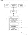
- Fig. 2 is a block diagram illustrating the main components of the mobile telephone 3 shown in Fig. 1 .
- the mobile telephone 3 includes a transceiver circuit 31 which transmits signals to, and receives signals from, the base station 5 via antenna 33.
- the operation of the transceiver circuit 31 is controlled by a controller 37 in accordance with software stored in memory 39.
- the software includes, among other things, an operating system 41, a communications control module 43, a radio resource control module 44, a mobility state determination module 45; a power consumption monitoring module 47, a measurement and reporting module 48; and an open mobile alliance device management module 49.
- the communications control module 43 controls communication with the base station 5 including, for example, allocation of resources to be used by the transceiver circuit 31 in its communications with the base station 5.
- the radio resource control module 44 controls the transition between various RRC modes and handles associated RRC signalling to/from the base station 5.
- the power consumption monitoring module 47 monitors applications running on the mobile telephone 3 and determines a current and/or desired power consumption state accordingly.
- the measurement and reporting module 48 performs signal measurements according to measurement events configured by the base station 5. The measurement and reporting module 48 also generates and sends measurement reports to the configuring base station 5.
- the open mobile alliance device management module 49 is operable to interface with the OMA DM entity 13 in the core network 7 for receiving and storing configuration parameters for the provision of information related to the operating state of the mobile telephone 3.
- Fig. 3 is a block diagram illustrating the main components of a donor base station 5.
- the base station 5 is a fixed communications node providing services to user equipment 3 within its coverage area.
- the base station 5 includes a transceiver circuit 51 which transmits signals to, and receives signals from, the mobile telephone 3 via at least one antenna 53.
- the base station 5 also transmits signals to and receives signals from the core network 7 and other neighbouring base stations 5 via a network interface 55 (for communicating with neighbouring base stations 5 and with the core network 7).
- the operation of the transceiver circuit 51 is controlled by a controller 57 in accordance with software stored in memory 59.
- the software includes, among other things, an operating system 61, a communications control module 63, a radio resource control module 65, a handover module 67, and a user equipment power management module 69.
- the communications control module 63 controls communications between the base station 5 and the mobile telephones 3, and the network devices such as the MME 9, the HSS 11, and the OMA DM 13.
- the radio resource control module 65 controls the radio communication resources used between the base station 5 and the mobile telephones 3 attached thereto.
- the handover module 67 configures measurements for the mobile telephones 3 to be carried out in relation to handover to another cell.
- the handover module 67 also configures mobility state and/or power consumption state reporting for the attached mobile telephones 3.
- the user equipment power management module 69 configures operation modes for the attached mobile telephones 3 (e.g. usage and parameters of DRX/DTX modes, connection release timers, RRC inactivity timers), in dependence of the mobility state and/or power consumption state reported by each mobile telephone 3.
- operation modes for the attached mobile telephones 3 e.g. usage and parameters of DRX/DTX modes, connection release timers, RRC inactivity timers
- the mobile telephone 3 and the base station 5 are described for ease of understanding as having a number of discrete modules (such as the communications control modules and the operation and maintenance modules). Whilst these modules may be provided in this way for certain applications, for example where an existing system has been modified to implement the invention, in other applications, for example in systems designed with the inventive features in mind from the outset, these modules may be built into the overall operating system or code and so these modules may not be discernible as discrete entities. These modules may also be implemented in software, hardware, firmware or a mix of these.
- Fig. 4 shows an example timing diagram illustrating a method performed by components of the communication system 1 when reporting a change in the mobility state of a mobile telephone 3.
- the mobile telephone 3 is operating in the RRC Idle mode.
- it receives a mobility state report request from the base station 5, e.g. as part of the system information that is being broadcast by this base station 5 within its cell(s).
- step s405 when the mobility state determination module 45 detects a change in the mobile telephone's 3 mobility state, it generates a mobility state report for sending to the network as soon as an RRC connection is established.
- the RRC module 44 initiates an RRC connection with the network by generating and sending (via the transceiver circuit 31) an 'RRC connection Request' message to the base station 5.
- the base station 5 provides the necessary RRC parameters by sending, in step s409, an 'RRC Connection Setup' message back to the mobile telephone 3.
- step s411 using the received RRC parameters, the mobile telephone 3 transitions into RRC connected mode operation, by changing the operation of its RRC module 44 accordingly.
- the RRC connected mode enables the mobile telephone 3 to send or receive data to/from the base station 5.
- the RRC module 44 generates and sends, to the base station 5, an 'RRC Connection Setup Complete' message, and also includes in this message the mobility state report generated by the mobility state determination module 45 in step s405.
- the base station 5 stores the received mobility state report, and makes it available to its RRC module 65, handover module 67, and UE power management module 69 to adjust their operation accordingly.
- the RRC module 65 selects new inactivity timers for this particular mobile telephone 3, by taking into account the reported mobility state.
- the base station 5 may share the received mobility state information with a further network node via its network interface 55 (e.g. with a neighbouring base station using the X2 interface).
- an idle mobile telephone can estimate its mobility by counting the number of serving cell changes in a given period of time and classify itself as either being in a normal, medium, or high mobility state.
- the base station broadcasts a request as part of the system information, which instructs the mobile telephone currently operating in the RRC Idle mode to report its mobility state to the network.
- Fig. 5 shows an example timing diagram illustrating a method performed by components of the communication system 1 when reporting a change in the power consumption state of a mobile telephone 3.
- This embodiment generally follows the first embodiment, however, instead of mobility state reporting, power consumption state reporting is performed.
- the mobile telephone 3 is operating in the RRC Idle mode.
- it receives a power consumption state report request from the base station 5, e.g. as part of the system information that is being broadcast by this base station 5 within its cell(s).
- step s505 when the power consumption monitoring module 47 detects a change in the mobile telephone's 3 power consumption state, it generates a power consumption state report for sending to the network as soon as an RRC connection is available. If an RRC connection is not already established, the RRC module 44, in step 507, generates and sends (via the transceiver circuit 31) an 'RRC connection Request' message to the base station 5. In response to this, the base station 5 provides the necessary RRC parameters by sending, in step s509, an 'RRC Connection Setup' message back to the mobile telephone 3.
- step s511 using the received RRC parameters, the mobile telephone 3 transitions into RRC connected mode operation, by changing the operation of its RRC module 44 accordingly.
- the RRC connected mode enables the mobile telephone 3 to send or receive data to/from the base station 5.
- step s513 the RRC module 44 generates and sends, to the base station 5, an 'RRC Connection Setup Complete' message, and also includes in this message the power consumption state report generated by the power consumption monitoring module 47 in step s505.
- step s515 the base station 5 stores the received power consumption state report, and makes it available to its RRC module 65, handover module 67, and UE power management module 69 to adjust their operation accordingly.
- the UE power management module 69 selects new operating parameters for this particular mobile telephone 3, by taking into account the reported power consumption state. For example, the UE power management module 69 might instruct the RRC module 65 to initiate a DRX/DTX mode operation for this mobile telephone 3. If this particular mobile telephone 3 is already operating in the DRX/DTX mode, the RRC module 65 might adjust the duty cycle so that further power savings can be achieved.
- the base station 5 may share the received power consumption state information with a further network node via its network interface 55 (e.g. with a neighbouring base station using the X2 interface).
- the mobile telephone can be instructed to report its power consumption state to the network.
- Fig. 6 shows an example timing diagram illustrating another method performed by components of the communication system 1 when reporting a change in the mobility state of a mobile telephone 3.
- the mobile telephone 3 is already operating in the RRC connected mode and is exchanging data with e.g. other user equipment or a network node via a cell of the serving base station 5.
- the base station's handover module 67 In step s603, the base station's handover module 67 generates and sends (via the transceiver circuit 51) an 'RRC Connection Reconfiguration' message to the mobile telephone 3.
- This message requests the mobile telephone 3 to perform measurements in relation to determining the timing of a handover to another base station. It does this by including in this message a 'MeasConfig' information element (IE), which specifies the kind of measurements and the conditions under which the measurements need to be initiated by the mobile telephone 3.
- IE 'MeasConfig' information element
- the 'MeasConfig' IE includes measurement parameters for at least one of the event types (i.e.
- Such parameters may specify, for example, a threshold signal level for a current serving cell, below which signal level the mobile telephone 3 will start the configured measurements. This will effectively result in the mobile telephone 3 performing a search for other base station cells to which it can be handed over when it is experiencing a degradation in signal quality within the current cell (e.g. due to the mobile telephone 3 moving away from the current base station 5).
- the 'RRC Connection Reconfiguration' message also includes a mobility state request for the mobile telephone 3, which is embedded in e.g. a 'ReportConfigEUTRA' IE within the 'RRC Connection Reconfiguration' message.
- the mobile telephone 3 configures, in step s605, its measurement and reporting module 48 in accordance with the received 'MeasConfig' IE and starts monitoring whether or not a condition defined therein is met.
- the mobile telephone 3 also configures its mobility state determination module 45 to monitor and report any change in the mobile telephone's 3 mobility state.
- step s607 the mobile telephone 3 confirms that the configuration has been successful by generating and sending an 'RRC Connection Reconfiguration Complete' message to the base station 5.
- the mobility state determination module 45 detects, in step s609, a change in the mobile telephone's 3 mobility state (e.g. due to the number of cell changes within the period specified by the TCRmax timer has changed), it proceeds to step s611 and generates a mobility state report according to the 'ReportConfigEUTRA' IE provided earlier by the base station 5.
- the measurement and reporting module 48 generates and sends a measurement report, in step s613, to the base station 5 in an 'RRC Measurement Report' message.
- This measurement report includes the mobility state report generated in step s611.
- this measurement report might also include the results of any cell measurements that the mobile telephone 3 has performed based on the received MeasConfig IE.
- the base station 5 After the base station 5 has received the Measurement Report, it stores the received mobility state report, in step s615, and makes it available to its RRC module 65, handover module 67, and UE power management module 69 to adjust their operation accordingly.
- the mobile telephone 3 reports its changed mobility state to the network as part of the radio measurement procedure, i.e. without unnecessary delay or without requiring a dedicated procedure to be initiated for the mobility state reporting. Consequently, this solution saves valuable system resources.
- Fig. 7 shows an example timing diagram illustrating another method performed by components of the communication system 1 when reporting a change in the power consumption state of a mobile telephone 3. This example is similar to the one discussed above with reference to Fig. 6 , however, instead of mobility state, power consumption state is reported.
- the mobile telephone 3 is already operating in the RRC connected mode and is exchanging data with e.g. other user equipment or a network node via a cell of the serving base station 5.
- the base station's handover module 67 In step s703, the base station's handover module 67 generates and sends (via the transceiver circuit 51) an 'RRC Connection Reconfiguration' message to the mobile telephone 3.
- This message requests the mobile telephone 3 to perform measurements in relation to determining the timing of a handover to another base station. It does this by including in this message a 'MeasConfig' information element (IE), as discussed above.
- the 'RRC Connection Reconfiguration' message also includes a power consumption state request for the mobile telephone 3, which is embedded in e.g. a 'ReportConfigEUTRA' IE within the 'RRC Connection Reconfiguration' message.
- the mobile telephone 3 configures, in step s705, its measurement and reporting module 48 in accordance with the received 'MeasConfig' IE and starts monitoring whether or not a condition defined therein is met.
- the mobile telephone 3 also configures its power consumption monitoring module 47 to monitor and report any change in the mobile telephone's 3 power consumption state.
- step s707 the mobile telephone 3 confirms that the configuration has been successful by generating and sending an 'RRC Connection Reconfiguration Complete' message to the base station 5.
- step s709 When the power consumption monitoring module 47 detects, in step s709, a change in the mobile telephone's 3 power consumption state (e.g. due to an application being turned on/off or an uplink/downlink transmit queue being emptied), it proceeds to step s711 and generates a power consumption state report according to the 'ReportConfigEUTRA' IE provided earlier by the base station 5.
- the measurement and reporting module 48 generates and sends a measurement report, in step s713, to the base station 5 in an 'RRC Measurement Report' message.
- This measurement report includes the power consumption state report generated in step s711.
- this measurement report might also include the results of any cell measurements that the mobile telephone 3 has performed based on the received MeasConfig IE.
- the base station 5 After the base station 5 has received the Measurement Report, it stores the received power consumption state report, in step s715, and makes it available to its RRC module 65, handover module 67, and UE power management module 69 to adjust their operation accordingly.
- the mobile telephone 3 reports its changed power consumption state to the network as part of the radio measurement procedure, i.e. without unnecessary delay or without requiring a dedicated procedure to be initiated for the power consumption state reporting.
- Fig. 8 shows an example timing diagram illustrating a method performed by components of the communication system 1 when exchanging optimised power consumption and/or mobility configuration between the home subscriber server 11 and the serving base station 5.
- some mobile telephones 3 might not support mobility state and/or power consumption state reporting and related optimisation. Therefore, before configuring such reporting, i.e. before performing step s603 or s703, the base station 5 might advantageously verify whether or not a particular mobile telephone 3 supports this feature.
- Table 1 illustrates some of the information stored in the home subscriber server 11 for each mobile telephone 3.
- information related to the UE context and whether or not optimized power consumption and/or mobility state reporting is supported is stored in the HSS 11 as follows:
- IMSI International Mobile Subscriber Identity
- Table 2 illustrates some of the information stored in the Mobility Management Entity 9 for each mobile telephone 3.
- information related to the UE context and whether or not optimized power consumption and/or mobility state reporting is supported is stored in the MME 9 as follows:
- IMSI is the main reference key ... ... Optimized power consumption Whether the UE can be configured for optimized power consumption Mobility state Whether UE can be configured for mobility state handling
- the base station 5 generates and sends, to the MME 9, an 'Initial UE Message', which includes an 'Attach Request' received from one of the mobile telephones (not shown) served by this base station 5.
- 'Attach Request' is typically generated by the mobile telephone upon first transitioning from RRC Idle to RRC Connected state, and is transmitted towards the core network 7 within an RRC Connection Setup Complete message sent to the base station 5.
- the MME 9 When the MME 9 receives the 'Attach Request', it generates and sends, in step s803, an 'Update Location Request' to the HSS 11. This message informs the HSS 11 about the mobile telephone's new location, i.e. its current serving base station / cell.
- the HSS retrieves from its UE context table the relevant subscription data for optimised power consumption and/or mobility state for the particular mobile telephone that provided the 'Attach Request'.
- the HSS 11 also generates and sends, in step s805, an 'Update LocationAck' message to the MME 9, and includes in this message an indication whether or not power consumption and/or mobility state reporting is supported by this mobile telephone.
- the HSS 11 includes this indication in e.g. a 'Subscription Data' IE embedded in the 'Update Location Ack' message.
- step s807 the MME 9 generates and sends, to the serving base station 5, an 'Initial Context Setup Request' message, and includes in this message the received 'Subscription Data' IE comprising the indication whether or not power consumption and/or mobility state reporting is supported by the particular mobile telephone.
- the MME 9 might also update its own UE context table if necessary.
- step s809 after the base station 5 has received the indication (included in the 'Subscription Data' IE) from the MME 9, it configures measurements and reporting for the mobile telephone accordingly. For example, if the received indication indicates that the particular mobile telephone supports mobility state reporting, the base station 5 proceeds to step s603 of Fig. 6 . Alternatively, if the received indication indicates that the particular mobile telephone supports power consumption state reporting, the base station 5 proceeds to step s703 of Fig. 7 .
- the indication included in the 'Subscription Data' IE
- Fig. 9 shows an example timing diagram illustrating a further method performed by components of the communication system 1 when reporting a change in the mobility state and/or power consumption state of a mobile telephone 3.
- an OMA DM entity 13 e.g. an application
- step s900 the mobile telephone 3 is attached to the network (either in RRC idle or RRC connected mode) via the base station 5.
- the OMA DM entity 13 In step s901, the OMA DM entity 13 generates and sends, via the base station 5, a non-access stratum (NAS) configuration message to the mobile telephone 3.
- the OMA DM entity 13 includes in this message, e.g. in the 'NAS configuration MO data' message shown in Fig. 9 , a mobility state request and/or power consumption state request in an information element, such as the 'lowerPowerConsumptionReportRequestforRRC' IE and/or the 'mobilityState-ReportRequestforRRC' IE, respectively.
- This message informs the mobile telephone 3 that it is allowed to report on its power consumption state and mobility state to the serving base station 5.
- the OMA DM entity 13 might also indicate a time periodicity for reporting the mobile telephone's 3 mobility state and/or power consumption state, using a suitable information element, such as a 'periodicityForlowerPowerConsumptionReportforRRC' IE and/or a 'periodicityFormobilityStateReportforRRC' IE, respectively.
- a suitable information element such as a 'periodicityForlowerPowerConsumptionReportforRRC' IE and/or a 'periodicityFormobilityStateReportforRRC' IE, respectively.
- the OMA DM entity 13 might also indicate a condition for reporting the mobile telephone's 3 mobility state and/or power consumption state, using an information element, such as a 'conditionForlowerPowerConsumptionReportforRRC' IE and/or a 'conditionFormobilityStateReportforRRC' IE, respectively.
- Such condition might include e.g. an update of the mobility state and
- the OMA DM module 49 of the mobile telephone 3 receives, and stores in memory 39 the received mobility state request and/or power consumption state request.
- the OMA DM module 49 also instructs the mobility state determination module 45 and/or the power consumption monitoring module 47 to generate an appropriate mobility state report and/or power consumption report, respectively.
- this report might be generated either immediately upon receiving the request(s), only upon a change in the mobility state and/or power consumption state of the mobile telephone 3, or periodically.
- step s905 the RRC module 44 generates and sends, to the base station 5, an RRC message, and includes in this message the mobility state report and/or power consumption report generated in step s903.
- the base station 5 stores the received power consumption state report and makes it available to its RRC module 65, handover module 67, and UE power management module 69 to adjust their operation accordingly.
- the mobile telephone's 3 NAS layer interfaces with the RRC module 44 to generate and provide an appropriate mobility state report and/or power consumption report to the network, based on the configuration provided by the OMA DM entity 13.
- Such configuration might include a time period for the sending of the mobility state and/or power consumption state report.
- Such configuration might include a condition for the sending the mobility state and/or power consumption state report(s). Therefore, in this example, there is no need for the base station 5 to generate a configuration for the mobile telephone's 3 a mobility state report and/or power consumption report.
- the base station requests the mobile telephone to report changes in its mobility state and/or power consumption state by sending an RRC Connection Reconfiguration message
- the network might use a System Information Block (SIB) message to transmit the mobility state request and/or power consumption report request to the mobile telephone.
- SIB System Information Block
- the mobile telephone reports its mobility state and/or power consumption state in an SIB response message.
- the mobile telephone generates and sends a mobility state and/or power consumption state report upon detecting a change in its respective mobility state and/or power consumption state.
- mobility state and/or power consumption state report might be generated and/or sent by the mobile telephone to the base station periodically, even if a change in the mobile telephone's mobility state and/or power consumption state is not detected.
- the mobility state request and/or power consumption report request is included in a ReportConfigEUTRA information element.
- request(s) might be included in any other suitable information element, such as the MeasConfig IE, or any other existing or dedicated information element.
- request(s) might be transmitted from the base station to the mobile telephone in any part (e.g. a header, payload, etc) of a suitable message.
- Such messages might be addressed and sent to a single mobile telephone, or sent to a group of mobile telephones, or sent to all mobile telephones (including idle and connected ones) served by this base station.
- the Subscription Data information element originates from the HSS (i.e. at step s805). However, it will be appreciated that in the absence of this information element, the MME might also generate and add this information element, at step s807, using its own UE context table.
- a mobile telephone based telecommunications system was described.
- the signalling techniques described in the present application can be employed in other communications system.
- Other communications nodes or devices may include user devices such as, for example, personal digital assistants, laptop computers, web browsers, etc.
- user devices such as, for example, personal digital assistants, laptop computers, web browsers, etc.
- the system can be used in a network having one or more fixed computing devices as well as or instead of the mobile communicating devices.
- the base station and the mobile telephone are described, for ease of understanding, as having a number of discrete modules. Whilst these modules may be provided in this way for certain applications, for example where an existing system has been modified to implement the invention, in other applications, for example in systems designed with the inventive features in mind from the outset, these modules may be built into the overall operating system or code and so these modules may not be discernible as discrete entities. These modules may also be implemented in software, hardware, firmware or a mix of these.
- the mobile telephone and the base station will include transceiver circuitry.
- this circuitry will be formed by dedicated hardware circuits.
- part of the transceiver circuitry may be implemented as software run by the corresponding controller.
- the software modules may be provided in compiled or un-compiled form and may be supplied to the base station or the relay station as a signal over a computer network, or on a recording medium. Further, the functionality performed by part or all of this software may be performed using one or more dedicated hardware circuits.
- Non-transitory computer readable media include any type of tangible storage media. Examples of non-transitory computer readable media include magnetic storage media (such as floppy disks, magnetic tapes, hard disk drives, etc.), optical magnetic storage media (e.g.
- the software modules may be provided to a computer using any type of transitory computer readable media.
- transitory computer readable media include electric signals, optical signals, and electromagnetic waves.
- Transitory computer readable media can provide the software modules to a computer via a wired communication line (e.g. electric wires, and optical fibers) or a wireless communication line.
Applications Claiming Priority (3)
| Application Number | Priority Date | Filing Date | Title |
|---|---|---|---|
| GB1213970.5A GB2504701A (en) | 2012-08-06 | 2012-08-06 | Determining current state of a mobile device |
| PCT/JP2013/004560 WO2014024411A1 (fr) | 2012-08-06 | 2013-07-26 | Système de communication |
| EP13827610.0A EP2742707B1 (fr) | 2012-08-06 | 2013-07-26 | Système de communication |
Related Parent Applications (2)
| Application Number | Title | Priority Date | Filing Date |
|---|---|---|---|
| EP13827610.0A Division EP2742707B1 (fr) | 2012-08-06 | 2013-07-26 | Système de communication |
| EP13827610.0A Division-Into EP2742707B1 (fr) | 2012-08-06 | 2013-07-26 | Système de communication |
Publications (2)
| Publication Number | Publication Date |
|---|---|
| EP3664485A1 true EP3664485A1 (fr) | 2020-06-10 |
| EP3664485B1 EP3664485B1 (fr) | 2023-07-19 |
Family
ID=46934924
Family Applications (2)
| Application Number | Title | Priority Date | Filing Date |
|---|---|---|---|
| EP13827610.0A Active EP2742707B1 (fr) | 2012-08-06 | 2013-07-26 | Système de communication |
| EP20152078.0A Active EP3664485B1 (fr) | 2012-08-06 | 2013-07-26 | Signalement de l'état de mobilité en rrc-idle |
Family Applications Before (1)
| Application Number | Title | Priority Date | Filing Date |
|---|---|---|---|
| EP13827610.0A Active EP2742707B1 (fr) | 2012-08-06 | 2013-07-26 | Système de communication |
Country Status (8)
| Country | Link |
|---|---|
| US (1) | US20150173017A1 (fr) |
| EP (2) | EP2742707B1 (fr) |
| JP (3) | JP6210109B2 (fr) |
| AU (1) | AU2013301054B2 (fr) |
| GB (1) | GB2504701A (fr) |
| IL (2) | IL236843B (fr) |
| RU (1) | RU2607978C2 (fr) |
| WO (1) | WO2014024411A1 (fr) |
Families Citing this family (17)
| Publication number | Priority date | Publication date | Assignee | Title |
|---|---|---|---|---|
| JP5391316B1 (ja) * | 2012-07-20 | 2014-01-15 | 株式会社Nttドコモ | 移動通信方法及び移動局 |
| GB2504701A (en) * | 2012-08-06 | 2014-02-12 | Nec Corp | Determining current state of a mobile device |
| CN106576296B (zh) * | 2014-03-26 | 2020-08-07 | 瑞典爱立信有限公司 | 取决于终端与接入点之间的相对速度的小区选择 |
| US9854620B2 (en) * | 2014-03-26 | 2017-12-26 | Telefonaktiebolaget Lm Ericsson | Connection setup between a mobile terminal and a moving base station based on joint movement detection |
| US20150365856A1 (en) * | 2014-06-17 | 2015-12-17 | Qualcomm Incorporated | Managing radio resource control (rrc) state transitions at a user equipment |
| US20160006661A1 (en) * | 2014-07-02 | 2016-01-07 | Acer Incorporated | Traffic classification methods, and apparatuses using the same |
| WO2016123809A1 (fr) | 2015-02-06 | 2016-08-11 | 华为技术有限公司 | Procédé et dispositif d'optimisation de signalisation |
| US11012577B2 (en) * | 2016-05-18 | 2021-05-18 | Telefonaktiebolaget Lm Ericsson (Publ) | Method for enabling differentiated charging support |
| WO2017222290A1 (fr) * | 2016-06-21 | 2017-12-28 | 엘지전자 주식회사 | Procédé pour rapporter l'état de commande de ressource radio rrc d'un terminal et appareil pour le prende en charge |
| US10015070B1 (en) * | 2016-06-28 | 2018-07-03 | Sprint Spectrum L.P. | Systems and methods for extending a handover trigger point for a wireless device operating in a connected mode |
| KR102290689B1 (ko) * | 2016-08-23 | 2021-08-17 | 후아웨이 테크놀러지 컴퍼니 리미티드 | 단말의 이동성 패턴을 관리하는 방법 및 장치 |
| WO2018069311A1 (fr) * | 2016-10-11 | 2018-04-19 | Telefonaktiebolaget Lm Ericsson (Publ) | Procédés et appareil destinés à adapter une comptabilité de commutation srs pour une procédure de mesure |
| EP3590282A1 (fr) * | 2017-03-03 | 2020-01-08 | Intel IP Corporation | Train à grande vitesse en nr (new radio) |
| WO2020193840A1 (fr) * | 2019-03-27 | 2020-10-01 | Nokia Technologies Oy | Signalement de consommation d'énergie de dispositif sans fil |
| US11229012B2 (en) * | 2019-11-18 | 2022-01-18 | Verzon Patent and Licensing Inc. | Dynamic modification of device band and radio access technology information |
| KR20210119217A (ko) * | 2020-03-24 | 2021-10-05 | 삼성전자주식회사 | 무선통신시스템에서 고정단말의 전력소모를 줄이기 위한 방법 및 장치 |
| WO2023136555A1 (fr) * | 2022-01-12 | 2023-07-20 | Samsung Electronics Co., Ltd. | Procédé et appareil pour réduire la consommation d'énergie dans un dispositif sans fil |
Citations (3)
| Publication number | Priority date | Publication date | Assignee | Title |
|---|---|---|---|---|
| WO2010017012A1 (fr) * | 2008-08-06 | 2010-02-11 | Interdigital Patent Holdings, Inc. | Procédures pour un fonctionnement en mode veille à évolution à long terme |
| WO2014010977A1 (fr) * | 2012-07-11 | 2014-01-16 | 엘지전자 주식회사 | Procédé de compte-rendu d'informations d'état de mobilité dans un système de communication sans fil et appareil le prenant en charge |
| EP2883375A1 (fr) * | 2012-07-12 | 2015-06-17 | LG Electronics Inc. | Procédé et appareil de transmission d'informations associées à la mobilité dans un système de communication sans fil |
Family Cites Families (83)
| Publication number | Priority date | Publication date | Assignee | Title |
|---|---|---|---|---|
| US6658262B1 (en) * | 1999-12-27 | 2003-12-02 | Telefonaktiebolget Lm Ericsson (Publ) | Method and system for power control order message management |
| KR100645743B1 (ko) * | 2001-12-28 | 2006-11-13 | 엘지노텔 주식회사 | 아이엠티-2000 시스템에서의 파워 관리 방법 |
| EP1520436B1 (fr) * | 2002-07-01 | 2006-06-21 | Nokia Corporation | Systeme et procede de distribution de messages de promotion a un terminal de communication |
| CN1198419C (zh) * | 2003-01-16 | 2005-04-20 | 大唐移动通信设备有限公司 | 基于下行导引时隙的功率控制方法 |
| US7020689B2 (en) * | 2003-03-07 | 2006-03-28 | Wegener Communications, Inc. | System and method for command transmission utilizing an email return path |
| KR100547771B1 (ko) * | 2003-03-13 | 2006-01-31 | 삼성전자주식회사 | 무선 랜 시스템에서 무선 접속 노드의 전력 제어 방법 |
| JP4218387B2 (ja) * | 2003-03-26 | 2009-02-04 | 日本電気株式会社 | 無線通信システム、基地局及びそれらに用いる無線リンク品質情報補正方法並びにそのプログラム |
| KR20050105286A (ko) * | 2003-03-26 | 2005-11-03 | 인터디지탈 테크날러지 코포레이션 | 고속 하향링크 패킷 접속 서비스의 제공 방법 및 그의 무선다중셀 통신 시스템 |
| EP1625673B1 (fr) * | 2003-05-13 | 2007-03-14 | Koninklijke Philips Electronics N.V. | Systeme de radiocommunications |
| US7808944B2 (en) * | 2003-11-21 | 2010-10-05 | Interdigital Technology Corporation | Wireless communication method and apparatus for controlling the transmission power of downlink and uplink coded composite transport channels based on discontinuous transmission state values |
| WO2005086403A1 (fr) * | 2004-02-27 | 2005-09-15 | Telefonaktiebolaget L M Ericsson | Optimisation d'utilisation de ressources dans un reseau a commutation par paquets |
| JP4458247B2 (ja) * | 2004-05-12 | 2010-04-28 | 日本電気株式会社 | 無線基地局装置設定システムおよび無線基地局装置設定方法 |
| WO2006004465A1 (fr) * | 2004-07-01 | 2006-01-12 | Telefonaktiebolaget L M Ericsson (Publ) | Commande de la puissance dans un reseau de communications et procede correspondant |
| EP1760933B1 (fr) * | 2004-08-06 | 2012-03-14 | Panasonic Corporation | Régulation par rétroaction pour des services multicast et broadcast |
| JP4538357B2 (ja) * | 2005-03-29 | 2010-09-08 | 株式会社エヌ・ティ・ティ・ドコモ | 伝送速度制御方法、移動局、無線基地局及び無線回線制御局 |
| EP1878131B1 (fr) * | 2005-05-04 | 2017-04-19 | Nokia Technologies Oy | Procédé, dispositif et programme informatique permettant de signaler des tailles d'étapes de régulation de puissance configurables pour un accès par paquets en voie ascendante à grande vitesse (hsupa) |
| US8150440B2 (en) * | 2005-09-23 | 2012-04-03 | Research In Motion Limited | System and method for reducing power consumed by a wireless communication device |
| US8045473B2 (en) * | 2005-11-28 | 2011-10-25 | Cisco Technology, Inc. | Tailored relief for congestion on application servers for real time communications |
| JP4589250B2 (ja) * | 2006-02-21 | 2010-12-01 | 富士通株式会社 | 無線通信システムにおける電力制御装置 |
| KR20080018148A (ko) * | 2006-08-23 | 2008-02-27 | 한국전자통신연구원 | 패킷 기반 셀룰라 시스템에서 방송 및 멀티캐스트 서비스데이터의 전송 및 수신 방법 |
| US7742448B2 (en) * | 2006-11-07 | 2010-06-22 | Motorola, Inc. | Optimizing topology learning in a multihop network |
| EP2127417B1 (fr) * | 2007-01-08 | 2016-11-02 | Nokia Technologies Oy | Procédé, appareil et système permettant de fournir des rapports concernant la qualité d'une voie d'un système de communication |
| US20080188260A1 (en) * | 2007-02-02 | 2008-08-07 | Motorola, Inc. | Method and apparatus for uplink power control in a communication system |
| RU2429567C2 (ru) * | 2007-02-12 | 2011-09-20 | Эл Джи Электроникс Инк. | Способы и процедуры для высокоскоростного доступа пользовательского оборудования |
| MX2009009507A (es) * | 2007-03-08 | 2009-10-12 | Interdigital Tech Corp | Carga de paginacion de compensacion y actualizaciones de area de seguimiento de asignacion. |
| EP1973355A1 (fr) * | 2007-03-19 | 2008-09-24 | Nokia Siemens Networks Gmbh & Co. Kg | Procédé et appareil de configuration de temporisateurs de mode |
| KR101325920B1 (ko) * | 2007-05-02 | 2013-11-07 | 삼성전자주식회사 | 업링크 제어 정보 전송 방법 및 이를 위한 단말 장치 |
| JP5321466B2 (ja) * | 2007-10-09 | 2013-10-23 | 日本電気株式会社 | 無線通信システム、無線通信方法、基地局、基地局の制御方法、及び基地局の制御プログラム |
| WO2009073525A1 (fr) * | 2007-11-29 | 2009-06-11 | Interdigital Patent Holdings, Inc. | Procédé et appareil pour un transfert adaptatif |
| US20100329150A1 (en) * | 2008-02-01 | 2010-12-30 | Johan Nielsen | Configuration of a node in a communications network |
| US8228855B2 (en) * | 2008-03-24 | 2012-07-24 | Qualcomm Incorporated | Uplink power headroom definition for E-DCH in CELL—FACH |
| WO2009154038A1 (fr) * | 2008-06-16 | 2009-12-23 | 日本電気株式会社 | Module de commande de station de base, station de base sans fil, dispositif de commande de station de base et procédé de commande de station de base |
| CN101651899B (zh) * | 2008-08-12 | 2012-12-05 | 中兴通讯股份有限公司 | Lte rrc连接重建立请求方法、原因值设置方法及终端 |
| CN101651903B (zh) * | 2008-08-12 | 2012-07-18 | 中兴通讯股份有限公司 | 一种控制终端运动状态评估的方法及终端 |
| US9155099B2 (en) * | 2008-10-27 | 2015-10-06 | Nec Corporation | Base station, radio communications system, control method of base station, radio communications method and control program |
| AU2009313191B2 (en) * | 2008-11-10 | 2014-03-13 | Blackberry Limited | Method and apparatus of transition to a battery efficient state or configuration by indicating end of data transmission in long term evolution |
| CN102224745A (zh) * | 2008-11-20 | 2011-10-19 | 诺基亚公司 | 基于通过用户设备的位置定位的无线系统改进 |
| JP5578082B2 (ja) * | 2008-11-26 | 2014-08-27 | 日本電気株式会社 | 基地局、基地局の送信電力制御方法、処理装置、プログラム、及び通信システム |
| TW201029489A (en) * | 2009-01-22 | 2010-08-01 | Htc Corp | Method of handling radio resource control connection establishment for a wireless communication system and related communication device |
| WO2010103534A2 (fr) * | 2009-02-23 | 2010-09-16 | Kumar Praveen | Démarrage d'un réseau de communications sans fil à l'aide d'un signal sans fil |
| CN101909322B (zh) * | 2009-06-03 | 2015-05-20 | 中兴通讯股份有限公司 | 一种移动终端及其上报移动状态的方法 |
| WO2011024310A1 (fr) * | 2009-08-31 | 2011-03-03 | 富士通株式会社 | Système de communication mobile, dispositif de station mobile, dispositif de station de base, et procédé de réduction des interférences d'onde électrique |
| WO2011039969A1 (fr) * | 2009-09-29 | 2011-04-07 | パナソニック株式会社 | Appareil de communication sans fil, station de base de communication sans fil et système de communication sans fil |
| KR101617888B1 (ko) * | 2010-01-08 | 2016-05-04 | 삼성전자주식회사 | 이동통신 시스템에서 고절전 수신모드 디바이스 통신을 위한 페이징 방법 및 장치와 그 시스템 |
| EP2852209B1 (fr) * | 2010-01-08 | 2017-03-29 | Interdigital Patent Holdings, Inc. | Procédé et unité de transmission/reception pour fournir de l'information d'identité d'une cellule CSG à un eNodeB |
| US20120287790A1 (en) * | 2010-01-11 | 2012-11-15 | Min Huang | Method and Apparatus |
| US8768335B2 (en) * | 2010-01-27 | 2014-07-01 | Lg Electronics Inc. | Method of performing a minimization of drive test (MDT) for specific area in wireless communication system |
| US8744534B2 (en) * | 2010-04-30 | 2014-06-03 | Apple Inc. | Methods and apparatus for preserving battery resources in a mobile communication device |
| US10536910B2 (en) * | 2010-05-28 | 2020-01-14 | Qualcomm Incorporated | Apparatus and method for random access channel power prioritization |
| US8842582B2 (en) * | 2010-06-04 | 2014-09-23 | Qualcomm Incorporated | Reducing power consumption by taking advantage of superior in-circuit duplexer performance |
| GB2483057B (en) * | 2010-08-20 | 2012-11-28 | Wireless Tech Solutions Llc | Apparatus, method and system for managing data transmission |
| GB2484347A (en) * | 2010-10-08 | 2012-04-11 | Nec Corp | Initiating energy saving mode based on the activity of mobile communications equipment over an LTE-A interface |
| KR101910899B1 (ko) * | 2010-11-05 | 2019-01-07 | 삼성전자 주식회사 | 이동통신 시스템에서 단말이 Power Headroom을 계산하는 방법 및 장치 |
| US9100913B2 (en) * | 2010-11-15 | 2015-08-04 | Samsung Electronics Co., Ltd. | Method and apparatus for optimizing power consumption of a terminal in a mobile communication system |
| US8934362B2 (en) * | 2011-01-06 | 2015-01-13 | Mediatek Inc. | Power control method to mitigate interference for in-device coexistence |
| AU2011364649A1 (en) * | 2011-04-08 | 2013-10-17 | Nokia Technologies Oy | Modification of mobility priority based on speed of user equipment and priority for cell operation |
| US9769763B2 (en) * | 2011-04-26 | 2017-09-19 | Telefonaktiebolaget L M Ericsson | Nodes and method for power control |
| US9030979B2 (en) * | 2011-05-11 | 2015-05-12 | Qualcomm Incorporated | Reducing power consumption in multi-threaded processor mobile devices |
| JP6055467B2 (ja) * | 2011-06-21 | 2016-12-27 | テレフオンアクチーボラゲット エルエム エリクソン(パブル) | アップリンク送信の送信電力制御を行うユーザ装置およびその装置における方法 |
| US9054749B2 (en) * | 2011-06-29 | 2015-06-09 | Broadcom Corporation | Optimizing power consumption in a near field communications (NFC) environment |
| KR101973462B1 (ko) * | 2011-07-08 | 2019-08-26 | 엘지전자 주식회사 | 접속 해제를 수행하는 방법 및 그 단말 |
| EP2753947B1 (fr) * | 2011-09-05 | 2017-10-25 | Nokia Technologies Oy | Transmission de paquets de positionnement |
| JP5662913B2 (ja) * | 2011-09-16 | 2015-02-04 | 株式会社日立製作所 | 無線通信システム及び基地局 |
| WO2013062388A2 (fr) * | 2011-10-27 | 2013-05-02 | 삼성전자 주식회사 | Procédé et appareil pour réduire de manière efficace la consommation d'énergie d'un terminal dans un système de communication mobile |
| US9014093B2 (en) * | 2011-11-02 | 2015-04-21 | Industrial Technology Research Institute | Direct communication method and direct communication device and coordinator device using the same |
| EP2749090B1 (fr) * | 2011-11-21 | 2020-04-15 | Telefonaktiebolaget LM Ericsson (publ) | Système de télécommunications amélioré, station de base, équipement utilisateur et procédé permettant de garantir des connexions de grande qualité |
| EP3253083B1 (fr) * | 2012-01-18 | 2021-03-24 | LG Electronics Inc. | Procédé et dispositif de commande sur la base de priorités multiples dans un système de communication sans fil |
| US9414409B2 (en) * | 2012-02-06 | 2016-08-09 | Samsung Electronics Co., Ltd. | Method and apparatus for transmitting/receiving data on multiple carriers in mobile communication system |
| US9526091B2 (en) * | 2012-03-16 | 2016-12-20 | Intel Corporation | Method and apparatus for coordination of self-optimization functions in a wireless network |
| WO2013147499A1 (fr) * | 2012-03-26 | 2013-10-03 | 삼성전자 주식회사 | Procédé et dispositif pour la préservation de données de mobilité lors d'une transition d'état d'un terminal, et pour un nouvel accès réussi dans un réseau cellulaire hétérogène dans un système de communication mobile |
| US8594699B1 (en) * | 2012-05-01 | 2013-11-26 | Blackberry Limited | Determining speed dependent scaling factors |
| US9515757B2 (en) * | 2012-05-11 | 2016-12-06 | Intel Corporation | Systems and methods for enhanced user equipment assistance information in wireless communication systems |
| US8874103B2 (en) * | 2012-05-11 | 2014-10-28 | Intel Corporation | Determining proximity of user equipment for device-to-device communication |
| US9014064B2 (en) * | 2012-05-11 | 2015-04-21 | Intel Corporation | Scheduling and hybrid automatic repeat request (HARQ) timing indication for an uplink-downlink (UL-DL) reconfiguration |
| CN104115534A (zh) * | 2012-05-18 | 2014-10-22 | 联发科技股份有限公司 | 用于功耗优化的增强ue数据传输 |
| CN104335644B (zh) * | 2012-06-08 | 2020-04-10 | 诺基亚技术有限公司 | 增强的节能优化配置处理 |
| US20150208264A1 (en) * | 2012-07-03 | 2015-07-23 | Nokia Corporation | Method and apparatus for adapting minimisation of drive testing reports to operational mode of user equipment using assistance information |
| US9693306B2 (en) * | 2012-07-11 | 2017-06-27 | Blackberry Limited | Mechanisms to support UE power preference signaling |
| US9516601B2 (en) * | 2012-07-19 | 2016-12-06 | Lg Electronics Inc. | Method and apparatus for determining transmission power of uplink control channel in wireless communication system |
| US9125137B2 (en) * | 2012-07-26 | 2015-09-01 | Lg Electronics Inc. | Method and terminal for applying an extended access barring |
| US9025461B2 (en) * | 2012-08-01 | 2015-05-05 | Qualcomm Incorporated | Power optimized behavior in mesh networks |
| US9445364B2 (en) * | 2012-08-02 | 2016-09-13 | Telefonaktiebolaget L M Ericsson (Publ) | Systems and methods for blocking excessive transmitter message signaling |
| GB2504701A (en) * | 2012-08-06 | 2014-02-12 | Nec Corp | Determining current state of a mobile device |
-
2012
- 2012-08-06 GB GB1213970.5A patent/GB2504701A/en not_active Withdrawn
-
2013
- 2013-07-26 EP EP13827610.0A patent/EP2742707B1/fr active Active
- 2013-07-26 RU RU2015103912A patent/RU2607978C2/ru active
- 2013-07-26 US US14/344,401 patent/US20150173017A1/en active Pending
- 2013-07-26 WO PCT/JP2013/004560 patent/WO2014024411A1/fr active Application Filing
- 2013-07-26 AU AU2013301054A patent/AU2013301054B2/en active Active
- 2013-07-26 EP EP20152078.0A patent/EP3664485B1/fr active Active
- 2013-07-26 JP JP2015506023A patent/JP6210109B2/ja active Active
-
2015
- 2015-01-22 IL IL236843A patent/IL236843B/en active IP Right Grant
-
2017
- 2017-09-13 JP JP2017175517A patent/JP6500957B2/ja active Active
-
2018
- 2018-08-05 IL IL260977A patent/IL260977B/en active IP Right Grant
-
2019
- 2019-03-15 JP JP2019048155A patent/JP6760426B2/ja active Active
Patent Citations (4)
| Publication number | Priority date | Publication date | Assignee | Title |
|---|---|---|---|---|
| WO2010017012A1 (fr) * | 2008-08-06 | 2010-02-11 | Interdigital Patent Holdings, Inc. | Procédures pour un fonctionnement en mode veille à évolution à long terme |
| WO2014010977A1 (fr) * | 2012-07-11 | 2014-01-16 | 엘지전자 주식회사 | Procédé de compte-rendu d'informations d'état de mobilité dans un système de communication sans fil et appareil le prenant en charge |
| US20150172907A1 (en) * | 2012-07-11 | 2015-06-18 | Lg Electronics Inc. | Method for reporting mobility state information in wireless communication system, and apparatus for supporting same |
| EP2883375A1 (fr) * | 2012-07-12 | 2015-06-17 | LG Electronics Inc. | Procédé et appareil de transmission d'informations associées à la mobilité dans un système de communication sans fil |
Non-Patent Citations (3)
| Title |
|---|
| CATT: "Analysis of UE Assistance Information for eDDA", 3GPP DRAFT; R2-122159 ANALYSES OF UE ASSISTANCE INFORMATION FOR EDDA, 3RD GENERATION PARTNERSHIP PROJECT (3GPP), MOBILE COMPETENCE CENTRE ; 650, ROUTE DES LUCIOLES ; F-06921 SOPHIA-ANTIPOLIS CEDEX ; FRANCE, vol. RAN WG2, no. Prague, Czech Republic; 20120521 - 20120525, 15 May 2012 (2012-05-15), XP050607159 * |
| CHINA UNICOM: "Discussion on UE Mobility Assistant Information", vol. RAN WG2, no. Qingdao, China; 20120813 - 20120817, 3 August 2012 (2012-08-03), XP050665045, Retrieved from the Internet <URL:http://www.3gpp.org/ftp/tsg_ran/WG2_RL2/TSGR2_79/Docs/> [retrieved on 20120803] * |
| QUALCOMM INCORPORATED ET AL: "Proposal for UE Assistance Information", 3GPP DRAFT; R2-122831_PROPOSAL FOR UE ASSISTANCE INFORMATION, 3RD GENERATION PARTNERSHIP PROJECT (3GPP), MOBILE COMPETENCE CENTRE ; 650, ROUTE DES LUCIOLES ; F-06921 SOPHIA-ANTIPOLIS CEDEX ; FRANCE, vol. RAN WG2, no. Prague, Czech Republic; 20120521 - 20120525, 15 May 2012 (2012-05-15), XP050607415 * |
Also Published As
| Publication number | Publication date |
|---|---|
| JP2015524626A (ja) | 2015-08-24 |
| IL260977B (en) | 2020-02-27 |
| JP2019115065A (ja) | 2019-07-11 |
| JP6760426B2 (ja) | 2020-09-23 |
| US20150173017A1 (en) | 2015-06-18 |
| RU2015103912A (ru) | 2016-08-27 |
| GB201213970D0 (en) | 2012-09-19 |
| WO2014024411A1 (fr) | 2014-02-13 |
| RU2607978C2 (ru) | 2017-01-11 |
| AU2013301054B2 (en) | 2015-04-16 |
| GB2504701A (en) | 2014-02-12 |
| IL236843B (en) | 2018-08-30 |
| JP6210109B2 (ja) | 2017-10-11 |
| JP2018011339A (ja) | 2018-01-18 |
| JP6500957B2 (ja) | 2019-04-17 |
| EP2742707A4 (fr) | 2015-11-11 |
| EP2742707A1 (fr) | 2014-06-18 |
| AU2013301054A1 (en) | 2014-04-03 |
| EP3664485B1 (fr) | 2023-07-19 |
| EP2742707B1 (fr) | 2020-02-26 |
Similar Documents
| Publication | Publication Date | Title |
|---|---|---|
| EP3664485B1 (fr) | Signalement de l'état de mobilité en rrc-idle | |
| US20210385749A1 (en) | Mobile telephone, apparatus, method and computer implementable instructions product | |
| JP6471828B1 (ja) | 無線通信システムと方法と無線基地局と制御局 | |
| KR102023446B1 (ko) | eNodeB, MME, eNodeB의 방법, 및 MME의 방법 | |
| JP6048592B2 (ja) | 低電力の無線通信装置の移動及び接続の管理 | |
| RU2578166C1 (ru) | Экономия энергии пользовательским оборудованием для межмашинной связи | |
| US20170048918A1 (en) | Macro-cell assisted small cell discovery and activation | |
| CN110225570B (zh) | 无线接入电信系统中的系统信息分配的方法、终端和小区 | |
| EP3031289B1 (fr) | Procédés, appareils et système pour déterminer des paramètres contribuant à l'état de connexion | |
| EP2982188B1 (fr) | Équipement utilisateur, noeud de réseau, et procédés pour gérer un mode de cycle de réception discontinue étendu | |
| KR101296578B1 (ko) | Lte 네트워크를 위한 페이징 노드 장치 및 페이징 방법 | |
| AU2015203413B2 (en) | Communication system | |
| JP2023544937A (ja) | 無線ネットワークにおけるページングリソース選択およびシステム情報伝送/入手のための方法、デバイス、システム | |
| KR20190052465A (ko) | 페이징 처리 장치 및 방법 | |
| WO2014025301A1 (fr) | Mécanisme permettant de rapporter des informations d'assistance relatives à la mobilité d'un ue | |
| WO2023206304A1 (fr) | Procédé et appareil de configuration pour cellule d'économie d'énergie de réseau | |
| WO2024062424A1 (fr) | Réduction de la consommation d'énergie d'un système de communication sans fil |
Legal Events
| Date | Code | Title | Description |
|---|---|---|---|
| PUAI | Public reference made under article 153(3) epc to a published international application that has entered the european phase |
Free format text: ORIGINAL CODE: 0009012 |
|
| STAA | Information on the status of an ep patent application or granted ep patent |
Free format text: STATUS: REQUEST FOR EXAMINATION WAS MADE |
|
| 17P | Request for examination filed |
Effective date: 20200115 |
|
| AC | Divisional application: reference to earlier application |
Ref document number: 2742707 Country of ref document: EP Kind code of ref document: P |
|
| AK | Designated contracting states |
Kind code of ref document: A1 Designated state(s): AL AT BE BG CH CY CZ DE DK EE ES FI FR GB GR HR HU IE IS IT LI LT LU LV MC MK MT NL NO PL PT RO RS SE SI SK SM TR |
|
| STAA | Information on the status of an ep patent application or granted ep patent |
Free format text: STATUS: EXAMINATION IS IN PROGRESS |
|
| STAA | Information on the status of an ep patent application or granted ep patent |
Free format text: STATUS: EXAMINATION IS IN PROGRESS |
|
| 17Q | First examination report despatched |
Effective date: 20201106 |
|
| RBV | Designated contracting states (corrected) |
Designated state(s): AL AT BE BG CH CY CZ DE DK EE ES FI FR GB GR HR HU IE IS IT LI LT LU LV MC MK MT NL NO PL PT RO RS SE SI SK SM TR |
|
| RIC1 | Information provided on ipc code assigned before grant |
Ipc: H04W 64/00 20090101ALN20220512BHEP Ipc: H04W 36/00 20090101ALN20220512BHEP Ipc: H04W 48/20 20090101ALN20220512BHEP Ipc: H04W 52/02 20090101ALN20220512BHEP Ipc: H04W 76/27 20180101ALI20220512BHEP Ipc: H04W 48/12 20090101ALI20220512BHEP Ipc: H04W 76/28 20180101ALI20220512BHEP Ipc: H04W 8/08 20090101AFI20220512BHEP |
|
| RIC1 | Information provided on ipc code assigned before grant |
Ipc: H04W 64/00 20090101ALN20220530BHEP Ipc: H04W 36/00 20090101ALN20220530BHEP Ipc: H04W 48/20 20090101ALN20220530BHEP Ipc: H04W 52/02 20090101ALN20220530BHEP Ipc: H04W 76/27 20180101ALI20220530BHEP Ipc: H04W 48/12 20090101ALI20220530BHEP Ipc: H04W 76/28 20180101ALI20220530BHEP Ipc: H04W 8/08 20090101AFI20220530BHEP |
|
| GRAP | Despatch of communication of intention to grant a patent |
Free format text: ORIGINAL CODE: EPIDOSNIGR1 |
|
| STAA | Information on the status of an ep patent application or granted ep patent |
Free format text: STATUS: GRANT OF PATENT IS INTENDED |
|
| INTG | Intention to grant announced |
Effective date: 20220719 |
|
| GRAJ | Information related to disapproval of communication of intention to grant by the applicant or resumption of examination proceedings by the epo deleted |
Free format text: ORIGINAL CODE: EPIDOSDIGR1 |
|
| STAA | Information on the status of an ep patent application or granted ep patent |
Free format text: STATUS: EXAMINATION IS IN PROGRESS |
|
| INTC | Intention to grant announced (deleted) | ||
| RIC1 | Information provided on ipc code assigned before grant |
Ipc: H04W 64/00 20090101ALN20221212BHEP Ipc: H04W 36/00 20090101ALN20221212BHEP Ipc: H04W 48/20 20090101ALN20221212BHEP Ipc: H04W 52/02 20090101ALN20221212BHEP Ipc: H04W 76/27 20180101ALI20221212BHEP Ipc: H04W 48/12 20090101ALI20221212BHEP Ipc: H04W 76/28 20180101ALI20221212BHEP Ipc: H04W 8/08 20090101AFI20221212BHEP |
|
| GRAP | Despatch of communication of intention to grant a patent |
Free format text: ORIGINAL CODE: EPIDOSNIGR1 |
|
| STAA | Information on the status of an ep patent application or granted ep patent |
Free format text: STATUS: GRANT OF PATENT IS INTENDED |
|
| RIC1 | Information provided on ipc code assigned before grant |
Ipc: H04W 64/00 20090101ALN20230109BHEP Ipc: H04W 36/00 20090101ALN20230109BHEP Ipc: H04W 48/20 20090101ALN20230109BHEP Ipc: H04W 52/02 20090101ALN20230109BHEP Ipc: H04W 76/27 20180101ALI20230109BHEP Ipc: H04W 48/12 20090101ALI20230109BHEP Ipc: H04W 76/28 20180101ALI20230109BHEP Ipc: H04W 8/08 20090101AFI20230109BHEP |
|
| INTG | Intention to grant announced |
Effective date: 20230208 |
|
| GRAS | Grant fee paid |
Free format text: ORIGINAL CODE: EPIDOSNIGR3 |
|
| GRAA | (expected) grant |
Free format text: ORIGINAL CODE: 0009210 |
|
| STAA | Information on the status of an ep patent application or granted ep patent |
Free format text: STATUS: THE PATENT HAS BEEN GRANTED |
|
| AC | Divisional application: reference to earlier application |
Ref document number: 2742707 Country of ref document: EP Kind code of ref document: P |
|
| AK | Designated contracting states |
Kind code of ref document: B1 Designated state(s): AL AT BE BG CH CY CZ DE DK EE ES FI FR GB GR HR HU IE IS IT LI LT LU LV MC MK MT NL NO PL PT RO RS SE SI SK SM TR |
|
| REG | Reference to a national code |
Ref country code: GB Ref legal event code: FG4D |
|
| REG | Reference to a national code |
Ref country code: CH Ref legal event code: EP |
|
| REG | Reference to a national code |
Ref country code: DE Ref legal event code: R096 Ref document number: 602013084291 Country of ref document: DE |
|
| REG | Reference to a national code |
Ref country code: IE Ref legal event code: FG4D |
|
| REG | Reference to a national code |
Ref country code: LT Ref legal event code: MG9D |
|
| REG | Reference to a national code |
Ref country code: NL Ref legal event code: MP Effective date: 20230719 |
|
| PGFP | Annual fee paid to national office [announced via postgrant information from national office to epo] |
Ref country code: DE Payment date: 20230719 Year of fee payment: 11 |
|
| REG | Reference to a national code |
Ref country code: AT Ref legal event code: MK05 Ref document number: 1590698 Country of ref document: AT Kind code of ref document: T Effective date: 20230719 |
|
| PG25 | Lapsed in a contracting state [announced via postgrant information from national office to epo] |
Ref country code: NL Free format text: LAPSE BECAUSE OF FAILURE TO SUBMIT A TRANSLATION OF THE DESCRIPTION OR TO PAY THE FEE WITHIN THE PRESCRIBED TIME-LIMIT Effective date: 20230719 |
|
| PG25 | Lapsed in a contracting state [announced via postgrant information from national office to epo] |
Ref country code: GR Free format text: LAPSE BECAUSE OF FAILURE TO SUBMIT A TRANSLATION OF THE DESCRIPTION OR TO PAY THE FEE WITHIN THE PRESCRIBED TIME-LIMIT Effective date: 20231020 |
|
| PG25 | Lapsed in a contracting state [announced via postgrant information from national office to epo] |
Ref country code: IS Free format text: LAPSE BECAUSE OF FAILURE TO SUBMIT A TRANSLATION OF THE DESCRIPTION OR TO PAY THE FEE WITHIN THE PRESCRIBED TIME-LIMIT Effective date: 20231119 |
|
| PG25 | Lapsed in a contracting state [announced via postgrant information from national office to epo] |
Ref country code: SE Free format text: LAPSE BECAUSE OF FAILURE TO SUBMIT A TRANSLATION OF THE DESCRIPTION OR TO PAY THE FEE WITHIN THE PRESCRIBED TIME-LIMIT Effective date: 20230719 Ref country code: RS Free format text: LAPSE BECAUSE OF FAILURE TO SUBMIT A TRANSLATION OF THE DESCRIPTION OR TO PAY THE FEE WITHIN THE PRESCRIBED TIME-LIMIT Effective date: 20230719 Ref country code: PT Free format text: LAPSE BECAUSE OF FAILURE TO SUBMIT A TRANSLATION OF THE DESCRIPTION OR TO PAY THE FEE WITHIN THE PRESCRIBED TIME-LIMIT Effective date: 20231120 Ref country code: NO Free format text: LAPSE BECAUSE OF FAILURE TO SUBMIT A TRANSLATION OF THE DESCRIPTION OR TO PAY THE FEE WITHIN THE PRESCRIBED TIME-LIMIT Effective date: 20231019 Ref country code: LV Free format text: LAPSE BECAUSE OF FAILURE TO SUBMIT A TRANSLATION OF THE DESCRIPTION OR TO PAY THE FEE WITHIN THE PRESCRIBED TIME-LIMIT Effective date: 20230719 Ref country code: LT Free format text: LAPSE BECAUSE OF FAILURE TO SUBMIT A TRANSLATION OF THE DESCRIPTION OR TO PAY THE FEE WITHIN THE PRESCRIBED TIME-LIMIT Effective date: 20230719 Ref country code: IS Free format text: LAPSE BECAUSE OF FAILURE TO SUBMIT A TRANSLATION OF THE DESCRIPTION OR TO PAY THE FEE WITHIN THE PRESCRIBED TIME-LIMIT Effective date: 20231119 Ref country code: HR Free format text: LAPSE BECAUSE OF FAILURE TO SUBMIT A TRANSLATION OF THE DESCRIPTION OR TO PAY THE FEE WITHIN THE PRESCRIBED TIME-LIMIT Effective date: 20230719 Ref country code: GR Free format text: LAPSE BECAUSE OF FAILURE TO SUBMIT A TRANSLATION OF THE DESCRIPTION OR TO PAY THE FEE WITHIN THE PRESCRIBED TIME-LIMIT Effective date: 20231020 Ref country code: FI Free format text: LAPSE BECAUSE OF FAILURE TO SUBMIT A TRANSLATION OF THE DESCRIPTION OR TO PAY THE FEE WITHIN THE PRESCRIBED TIME-LIMIT Effective date: 20230719 Ref country code: AT Free format text: LAPSE BECAUSE OF FAILURE TO SUBMIT A TRANSLATION OF THE DESCRIPTION OR TO PAY THE FEE WITHIN THE PRESCRIBED TIME-LIMIT Effective date: 20230719 |
|
| PG25 | Lapsed in a contracting state [announced via postgrant information from national office to epo] |
Ref country code: PL Free format text: LAPSE BECAUSE OF FAILURE TO SUBMIT A TRANSLATION OF THE DESCRIPTION OR TO PAY THE FEE WITHIN THE PRESCRIBED TIME-LIMIT Effective date: 20230719 |
|
| REG | Reference to a national code |
Ref country code: CH Ref legal event code: PL |
|
| REG | Reference to a national code |
Ref country code: BE Ref legal event code: MM Effective date: 20230731 |
|
| PG25 | Lapsed in a contracting state [announced via postgrant information from national office to epo] |
Ref country code: LU Free format text: LAPSE BECAUSE OF NON-PAYMENT OF DUE FEES Effective date: 20230726 |
|
| PG25 | Lapsed in a contracting state [announced via postgrant information from national office to epo] |
Ref country code: LU Free format text: LAPSE BECAUSE OF NON-PAYMENT OF DUE FEES Effective date: 20230726 |
|
| PG25 | Lapsed in a contracting state [announced via postgrant information from national office to epo] |
Ref country code: ES Free format text: LAPSE BECAUSE OF FAILURE TO SUBMIT A TRANSLATION OF THE DESCRIPTION OR TO PAY THE FEE WITHIN THE PRESCRIBED TIME-LIMIT Effective date: 20230719 |
|
| PG25 | Lapsed in a contracting state [announced via postgrant information from national office to epo] |
Ref country code: SM Free format text: LAPSE BECAUSE OF FAILURE TO SUBMIT A TRANSLATION OF THE DESCRIPTION OR TO PAY THE FEE WITHIN THE PRESCRIBED TIME-LIMIT Effective date: 20230719 Ref country code: RO Free format text: LAPSE BECAUSE OF FAILURE TO SUBMIT A TRANSLATION OF THE DESCRIPTION OR TO PAY THE FEE WITHIN THE PRESCRIBED TIME-LIMIT Effective date: 20230719 Ref country code: ES Free format text: LAPSE BECAUSE OF FAILURE TO SUBMIT A TRANSLATION OF THE DESCRIPTION OR TO PAY THE FEE WITHIN THE PRESCRIBED TIME-LIMIT Effective date: 20230719 Ref country code: EE Free format text: LAPSE BECAUSE OF FAILURE TO SUBMIT A TRANSLATION OF THE DESCRIPTION OR TO PAY THE FEE WITHIN THE PRESCRIBED TIME-LIMIT Effective date: 20230719 Ref country code: DK Free format text: LAPSE BECAUSE OF FAILURE TO SUBMIT A TRANSLATION OF THE DESCRIPTION OR TO PAY THE FEE WITHIN THE PRESCRIBED TIME-LIMIT Effective date: 20230719 Ref country code: CZ Free format text: LAPSE BECAUSE OF FAILURE TO SUBMIT A TRANSLATION OF THE DESCRIPTION OR TO PAY THE FEE WITHIN THE PRESCRIBED TIME-LIMIT Effective date: 20230719 Ref country code: SK Free format text: LAPSE BECAUSE OF FAILURE TO SUBMIT A TRANSLATION OF THE DESCRIPTION OR TO PAY THE FEE WITHIN THE PRESCRIBED TIME-LIMIT Effective date: 20230719 Ref country code: CH Free format text: LAPSE BECAUSE OF NON-PAYMENT OF DUE FEES Effective date: 20230731 Ref country code: MC Free format text: LAPSE BECAUSE OF FAILURE TO SUBMIT A TRANSLATION OF THE DESCRIPTION OR TO PAY THE FEE WITHIN THE PRESCRIBED TIME-LIMIT Effective date: 20230719 |