EP3664375B1 - Paketverarbeitungsverfahren und netzwerkvorrichtung - Google Patents
Paketverarbeitungsverfahren und netzwerkvorrichtung Download PDFInfo
- Publication number
- EP3664375B1 EP3664375B1 EP17922213.8A EP17922213A EP3664375B1 EP 3664375 B1 EP3664375 B1 EP 3664375B1 EP 17922213 A EP17922213 A EP 17922213A EP 3664375 B1 EP3664375 B1 EP 3664375B1
- Authority
- EP
- European Patent Office
- Prior art keywords
- packet
- network device
- conversion module
- moment
- media conversion
- Prior art date
- Legal status (The legal status is an assumption and is not a legal conclusion. Google has not performed a legal analysis and makes no representation as to the accuracy of the status listed.)
- Active
Links
Images
Classifications
-
- H—ELECTRICITY
- H04—ELECTRIC COMMUNICATION TECHNIQUE
- H04J—MULTIPLEX COMMUNICATION
- H04J3/00—Time-division multiplex systems
- H04J3/02—Details
- H04J3/06—Synchronising arrangements
- H04J3/0635—Clock or time synchronisation in a network
- H04J3/0638—Clock or time synchronisation among nodes; Internode synchronisation
- H04J3/0644—External master-clock
-
- H—ELECTRICITY
- H04—ELECTRIC COMMUNICATION TECHNIQUE
- H04J—MULTIPLEX COMMUNICATION
- H04J3/00—Time-division multiplex systems
- H04J3/02—Details
- H04J3/06—Synchronising arrangements
- H04J3/0635—Clock or time synchronisation in a network
- H04J3/0638—Clock or time synchronisation among nodes; Internode synchronisation
- H04J3/0658—Clock or time synchronisation among packet nodes
- H04J3/0661—Clock or time synchronisation among packet nodes using timestamps
- H04J3/0667—Bidirectional timestamps, e.g. NTP or PTP for compensation of clock drift and for compensation of propagation delays
-
- H—ELECTRICITY
- H04—ELECTRIC COMMUNICATION TECHNIQUE
- H04J—MULTIPLEX COMMUNICATION
- H04J3/00—Time-division multiplex systems
- H04J3/02—Details
- H04J3/06—Synchronising arrangements
- H04J3/0635—Clock or time synchronisation in a network
- H04J3/0638—Clock or time synchronisation among nodes; Internode synchronisation
- H04J3/0658—Clock or time synchronisation among packet nodes
- H04J3/0661—Clock or time synchronisation among packet nodes using timestamps
- H04J3/067—Details of the timestamp structure
-
- H—ELECTRICITY
- H04—ELECTRIC COMMUNICATION TECHNIQUE
- H04J—MULTIPLEX COMMUNICATION
- H04J3/00—Time-division multiplex systems
- H04J3/02—Details
- H04J3/06—Synchronising arrangements
- H04J3/0635—Clock or time synchronisation in a network
- H04J3/0685—Clock or time synchronisation in a node; Intranode synchronisation
- H04J3/0697—Synchronisation in a packet node
-
- H—ELECTRICITY
- H04—ELECTRIC COMMUNICATION TECHNIQUE
- H04L—TRANSMISSION OF DIGITAL INFORMATION, e.g. TELEGRAPHIC COMMUNICATION
- H04L7/00—Arrangements for synchronising receiver with transmitter
- H04L7/04—Speed or phase control by synchronisation signals
-
- H—ELECTRICITY
- H04—ELECTRIC COMMUNICATION TECHNIQUE
- H04J—MULTIPLEX COMMUNICATION
- H04J3/00—Time-division multiplex systems
- H04J3/02—Details
- H04J3/06—Synchronising arrangements
- H04J3/0635—Clock or time synchronisation in a network
- H04J3/0682—Clock or time synchronisation in a network by delay compensation, e.g. by compensation of propagation delay or variations thereof, by ranging
Definitions
- This application relates to the network communications field, and in particular, to a packet processing method and a network device in the network communications field.
- PTP Precision Time Protocol
- a core idea of the IEEE 1588 protocol is to use a master-slave clock mode.
- a master device periodically issues PTP packets, a slave device receives timestamp information sent by the master device.
- a master-slave line time delay and a master-slave time offset are calculated based on the timestamp information, and a local time is adjusted by using the time offset, so that a slave device time is kept consistent with a master device time, to implement time synchronization.
- the IEEE 1588 protocol requires that a delay between a stamping point and a physical layer medium (for example, an optical fiber) be stable and that there be no asymmetric delay change.
- a delay in a PHY chip is largely considered.
- internal processing such as first in first out (First-In-First-Out, FIFO), also exists between the stamping point and an egress of a media conversion module, and a delay of the internal processing is uncertain.
- An existing solution is to estimate a delay of the media conversion module based on internal circuit processing. In this solution, the obtained delay may be inaccurate, resulting in relatively low synchronization performance of the 1588 protocol.
- US2010309932 relates to method and system for compensated time stamping for time-sensitive network communications.
- US2016043823 relates to method, apparatus, and system for generating timestamp.
- WO2007137085 relates to network time protocol precision timestamping service.
- US2005207387 relates to method and apparatus for aligning time references when separated by an unreliable data packet network.
- This application provides a packet processing method and a network device, so as to accurately determine a delay of processing a packet by a media conversion module, and help improve synchronization performance of a 1588 protocol.
- a communications network and a communications device have a strict requirement for clock synchronization.
- the mobile communications system also has a stricter requirement for clock synchronization precision.
- IEEE 1588 was originally generated because precise time control is required in the industrial control field. However, because the IEEE 1588 supports hardware stamping, the IEEE 1588 can obtain high-precision time synchronization of a sub-microsecond ⁇ s level.
- the IEEE 1588 was introduced into a telecommunications network by the International Telecommunication Union-Telecommunication Standardization Sector (International Telecommunication Union-Telecommunication Sector, ITU-T) to provide precise time synchronization for a time division wireless system such as time division-synchronous code division multiple access (Time Division-Synchronous Code Division Multiple Access, TD-SCDMA), code division multiple access 2000 (Code Division Multiple Access 2000, CDMA 2000), or long term evolution-time division duplex (Long Term Evolution-Time Division Duplex, LTE-TDD).
- time division-synchronous code division multiple access Time Division-Synchronous Code Division Multiple Access, TD-SCDMA
- code division multiple access 2000 Code Division Multiple Access 2000
- CDMA 2000 Code Division Multiple Access 2000
- LTE-TDD Long Term Evolution-Time Division Duplex
- the following describes in detail a concept, a term, and a requirement of time synchronization, and a technical principle, a networking scenario, and a deployment consideration of the 1588 protocol from a technical perspective.
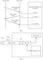
- FIG 1 is a schematic diagram of a time synchronization process of an IEEE 1588 protocol. Used packets are a synchronization (Sync) packet, a delay request (Delay_Req) packet, and a delay response (Delay_Resp) packet.
- a master clock sends a Sync packet to a slave clock at a moment t 1 , where the Sync packet carries a sending time of a t 1 timestamp of the Sync packet.
- the slave clock receives the Sync packet at a moment t 2 , generates a t 2 timestamp locally, and obtains the t 1 timestamp from the Sync packet.
- the slave clock sends a Delay_Req packet to the master clock at a moment t 3 , and generates a t 3 timestamp locally.
- the master clock receives the Delay_Req packet at a moment t 4 , and generates a t 4 timestamp locally. Then, the master clock adds the t 4 timestamp to the Delay_Resp packet, and returns the Delay _Resp packet including the t 4 timestamp to the slave clock.
- the slave clock receives the Delay _Resp packet, and extracts the t 4 timestamp from the packet. In this way, the slave clock obtains four timestamps.
- a master-slave line Delay and a master-slave time Offset can be calculated from the four timestamps.
- a line delay from the master clock to the slave clock is set to a delay 1
- a line delay from the slave clock to the master clock is set to a delay 2.
- Delay T 2 ⁇ T 1 + T 4 ⁇ T 3 2
- Offset T 2 ⁇ T 1 ⁇ T 4 ⁇ T 3 2
- the slave clock can adjust time of the slave clock based on a calculated offset value, so as to implement synchronization with the master clock.
- the foregoing calculation is based on an assumption that the link delay from the master clock to the slave clock is equal to the link delay from the slave clock to the master clock.
- FIG 2 is a schematic diagram of a possible application scenario according to an embodiment of this application.
- FIG 2 is a partial internal structural diagram of a network device.
- the network device includes an optical module, a PHY chip, a system clock, and a 1588 protocol unit, and delays before and after the optical module are a delay 1 and a delay 2 respectively.
- the PHY may be implemented by using a field programmable gate array (field programmable gate array, FPGA) or an application-specific integrated circuit (application specific integrated circuit, ASIC).
- the PHY may include a serdes, a bit demultiplexer (bit demultiplexer, bit demux) circuit, a first in first out buffer (first in first out buffer, FIFO buffer), a descrambling circuit, and an aggregation circuit.
- the PHY may be a component in a network interface card (network interface card, NIC), and the NIC may be a line card (line card, LC) or a physical interface card (physical interface card, PIC).
- the PHY may be connected to a media access controller (media access controller, MAC) by using a media independent interface (media independence interface, MII).
- the PHY chip may include one PHY or a plurality of PHYs.
- the optical module is used for optical-to-electrical conversion.
- a transmitting interface converts an electrical signal into an optical signal.
- a receiving interface converts the optical signal into the electrical signal.
- 1588 is actually a master-slave synchronization system.
- the master clock periodically issues PTP time synchronization and time information
- the slave clock port receives timestamp information sent by the master clock port.
- the system calculates a master-slave line time delay and a master-slave time offset based on the timestamp information, and adjusts a local time by using the time offset, so that a frequency and a phase of a slave device time are kept consistent with those of a master device time.
- the 1588 protocol can simultaneously implement frequency synchronization and phase synchronization.
- the system clock is a clock system.
- the system clock is a circuit that includes an oscillator (a signal source), a timing wake-up device, a frequency divider, and the like.
- the system clock is a pulse of an entire system.
- a processor needs to be driven by the clock to complete instruction execution.
- a timestamp generated when the network device sends a packet is completed by a service chip next preceding the media conversion module.
- a timestamp generated when the network device receives a packet is completed by a service chip next following the media conversion module.
- the timestamp generated when the network device sends the packet does not consider a time period during which the packet passes through the media conversion module, and a time of actually sending the packet should be later than the timestamp generated when the packet is sent.
- the timestamp generated when the network device receives the packet does not consider a time period during which the packet passes through the media conversion module.
- the time of actually receiving the packet should be earlier than the timestamp generated when the packet is received.
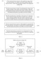
- FIG 3 is a schematic block diagram of a packet processing method 100 according to an embodiment of this application.
- the method 100 may be performed by a control unit in a network device.
- the control unit may be implemented by a CPU or an FPGA.
- the method 100 includes the following steps.
- a first network device receives a first packet by using a first receiving interface of a media conversion module of the first network device, where the first packet includes a first alignment marker AM.
- the first network device sends a second packet by using a first sending interface of the media conversion module, where the second packet includes the first AM, and the second packet is the first packet processed by the media conversion module.
- the first network device calculates a time interval T 1 between a time at which the media conversion module receives the first packet including the first AM and a time at which the media conversion module sends the second packet including the first AM.
- the first network device receives a third packet by using the first receiving interface, and sends, by using the first sending interface, the third packet processed by the media conversion module.
- the first network device uses the T 1 to compensate for a first timestamp at which the first network device receives or sends the third packet.
- the media conversion module is an optical module.
- the optical module may further convert the electrical signal into the optical signal.
- optical module As an example to describe the technical solutions in this embodiment of this application in detail.
- a data stream may be input into the media conversion module, and the data stream may include a plurality of packets.
- the data stream may be data of a physical layer
- the packet may be data of a MAC layer.
- the data stream may include a plurality of data blocks, and each data block in the data stream is obtained by performing physical layer encoding on an Ethernet frame stream.
- An alignment marker (alignment marker, AM) is periodically inserted after the physical layer encoding is performed on the Ethernet frame stream. Such a cycle may be referred to as a data cycle.
- the AM is also a data block. Inserting the AM into the data stream may mean that the AM is included in a packet. For ease of understanding, the following first describes in detail the data block in the data stream.
- the physical layer encoding may be 8-bit/10-bit encoding, or may be 64-bit/66-bit encoding.
- a quantity of bits included in one data block is 10.
- a quantity of bits included in one data block is 66.
- two bits may be a synchronization header.
- two bits may be a synchronization header.
- data transmitted in one data cycle may be 16384 data blocks.
- the 16384 data blocks include the AM and 16383 data blocks.
- the AM is transmitted before the 16383 data blocks.
- a quantity of bits included in each of the 16384 data blocks is 64.
- the data transmitted in one data cycle includes one AM and a plurality of data blocks, and the plurality of data blocks form a data block group.
- data blocks other than the AM in the data transmitted in one data cycle are data blocks in the data block group.
- the quantity of bits included in each of the plurality of data blocks is equal to the quantity of bits included in the AM.
- steps S110, S120, and S130 may be performed only once, and the calculated T 1 is stored in the first network device.
- the T 1 may be directly used to compensate for the timestamp at which the third packet is sent or received.
- steps S 140 and S150 may be performed for a plurality of times.
- the third packet may be the first packet.
- the first network device may compensate, in real time, the timestamp at which the first network device receives or sends the first packet.
- the first network device may add, to the first packet at the first sending interface of the media conversion module, an interval between the time at which the first packet arrives at the first receiving interface and the time at which the first packet arrives at the first sending interface, so that the second network device can calculate an accurate moment at which the first network device sends the first packet.
- the third packet may further be a packet received after the first network device receives the first packet by using the second receiving interface.
- the first network device may calculate a delay in advance, and perform compensation in a subsequent packet. This example is used to describe this application in the following, but this embodiment of this application is not limited thereto.
- a time interval before and after a packet passes through the media conversion module is recorded, and the time interval is used to correct a timestamp of sending or receiving a packet. This can accurately determine the delay of the packet through internal processing of the media conversion module, and further improve synchronization performance of a 1588 protocol.
- the calculating, by the first network device, a time interval T 1 between a time at which the media conversion module receives the first packet including the first AM and a time at which the media conversion module sends the second packet including the first AM includes: recording, by the first network device, a first moment when receiving the first packet by using the first receiving interface and when determining that the first packet includes the first AM; recording, by the first network device, a second moment when sending the second packet by using the first sending interface and when determining that the second packet includes the first AM; and determining, by the first network device, a time interval between the first moment and the second moment as the time interval T 1 .
- the first network device may start a counter at the first moment.
- the first network device may stop the counter at the second moment, and obtain a count value N, where N is a positive integer, and a clock cycle of the counter is t. Further, the first network device may determine N * t as the T 1 . It should be understood that the clock cycle t of the counter may mean that the count value is increased by 1 at an interval of a time t.
- the delay measurement method may be implemented by both hardware and software.
- a media conversion module 200 of the network device in FIG 4 is used as an example to describe the technical solutions in this embodiment of this application in detail.
- the media conversion module 200 includes at least a network interface 210, a service processing unit 220, and a delay measurement unit 230.
- the media conversion module 200 may be configured to perform some or all of the steps or the procedures of the method 100 for measuring a delay in this embodiment of this application.
- a processing requirement of the service processing unit 220 is that parallel-to-serial conversion of data usually needs to be performed by using the network interface 210.
- the network interface may be a serdes interface, and the serdes interface may be either a serializer or a deserializer.
- Parallel-to-serial conversion is a mainstream time division multiplexing (time division multiplexing, TDM) and peer-to-peer (peer-to-peer, P2P) serial communications technology.
- TDM time division multiplexing
- P2P peer-to-peer
- a plurality of low rate parallel signals are converted into high rate serial signals at a transmit end, and high rate serial signals are transmitted through a transmission medium (an optical cable or a copper wire).
- the high rate serial signals are converted back into low rate parallel signals at a receive end.
- the data stream after the parallel-to-serial conversion may be a data stream into which an AM has been inserted.
- inserting the AM into the data stream may be performed by the media conversion module 200, or may be performed by a service chip before the data stream flows into the media conversion module 200. This is not limited in this embodiment of this application.
- a data stream that passes through the network interface 210 may be bypassed to the delay measurement unit 230.
- the delay measurement unit 230 may identify a specific AM in the data stream.
- the data stream is further processed by the service processing unit 220, and before the data stream flows out of the network interface 210, the data stream is bypassed to the delay measurement unit 230 again, and the specific AM is identified again.
- the delay measurement unit 230 may respectively generate two pulse signals, and the two pulse signals are recorded as an FP1 and an FP2 respectively.
- a timer may be started inside the delay measurement unit 230, and the FP1 and the FP2 are used as a start and an end of the timer.
- a time recorded by the timer at an end moment may be a delay during which the data stream passes through the service processing unit 220.
- a high-frequency counter may be started inside the delay measurement unit 230.
- the FP1 and the FP2 are used as a start and an end of the counter, and a product of a value recorded by the high-frequency counter at an end moment and a cycle of the high-frequency counter may be used as a delay during which the data stream passes through the service processing unit 220.
- the delay measured by the delay measurement unit 230 may be used to correct a timestamp at which the network device receives or sends some packets.
- the method further includes: receiving, by the first network device, a fourth packet by using a second receiving interface of the media conversion module, where the fourth packet includes a second AM; sending, by the first network device, a fifth packet by using a second sending interface of the media conversion module, where the fifth packet includes the second AM, and the fifth packet is the fourth packet processed by the media conversion module; calculating, by the first network device, a time interval T 2 between a time at which the media conversion module receives the fourth packet including the second AM and a time at which the media conversion module sends the fifth packet including the second AM; and receiving, by the first network device, a sixth packet by using the second receiving interface, and sending, by using the second sending interface, the sixth packet processed by the media conversion module, where a receiving direction and a sending direction of the third packet are opposite to those of the sixth packet, and the first network device uses the T 2 to compensate for a second timestamp at which the first network device receives or sends the sixth packet.
- the sixth packet may be the fourth packet, or the sixth packet is a packet received after the first network device receives the fourth packet by using the second receiving interface.
- the media conversion module 200 may be a media conversion module of a network device.
- a delay during which a data stream in either of the receiving direction and the sending direction of the network device passes through the service processing unit 220 in the media conversion module 200 may be measured by using the foregoing method 100.
- the any direction may be the sending direction or the receiving direction.
- a delay during which a data stream in the other direction passes through the service processing unit in the media conversion module 200 may be measured by using an existing delay measurement method.
- the delay of the media conversion module may be estimated based on internal circuit processing.
- the method 100 may also be applied in two directions of the network device, to be specific, the method 100 is used in both the receiving direction and the sending direction. This is not limited in this embodiment of this application.
- the receiving interface and the sending interface in this embodiment of this application may be multiplexed, to be specific, it may be understood that the first receiving interface may be the second sending interface, and the first sending interface may be the second receiving interface. A delay in one direction may be first measured, and then a delay in the other direction is measured.
- a delay of internal processing of the media conversion module is used to compensate for timestamps in both the receiving direction and the sending direction. This can further improve synchronization performance of a 1588 protocol.
- the third packet is a packet that is sent by a first service chip of the first network device to a second network device by using the media conversion module, and that the first network device uses the T 1 to compensate for a first timestamp at which the first network device sends the third packet includes: using, by the first network device, a sum of the first timestamp and the T 1 as a moment at which the first network device sends the third packet to the second network device, where the first timestamp is a moment at which the third packet arrives at the first receiving interface.
- the packet when the first network device sends the packet to the second network device, the packet first needs to be processed by using the service chip in the first network device, and then the processed packet is sent by using the media conversion module.
- the third packet may be a packet processed by the first service chip.
- the third packet is a packet that is sent by a second network device to a second service chip of the first network device by using the media conversion module, and that the first network device uses the T 1 to compensate for a first timestamp at which the first network device receives the third packet includes: using, by the first network device, a difference between the first timestamp and the T 1 as a moment at which the first network device receives the third packet, where the first timestamp is a moment at which the third packet arrives at the first sending interface.
- a 1588 clock synchronization system usually includes a master device and a slave device that exchange a packet.
- both the master device and the slave device may include the media conversion module 200.
- the foregoing method 100 may be used to correct the timestamps of the receiving direction and the sending direction of the master device.
- the slave device is used as an example.
- the slave device may use a sum of the measured T 1 and the timestamp of sending a packet as a moment of sending the packet to the master device, and the slave device may also use a difference between the measured T 2 and the timestamp of receiving the packet as a moment of receiving the packet sent by the master device.
- the master device may add the measured T 1 to the packet so that the slave device may calculate an accurate moment at which the master device sends the packet.
- using the method 100 to correct the timestamp for any direction of any device in the 1588 clock synchronization system helps improve the synchronization performance of the 1588 protocol.
- the third packet is a synchronization packet sent by a second network device to the first network device, where the synchronization packet carries a third timestamp at which the second network device sends the synchronization packet.
- the sixth packet is a delay request packet sent by the first network device to the second network device, where the second network device is a master device of the first network device, and the first network device is a slave device of the second network device.
- the method further includes: obtaining, by the first network device from the synchronization packet, a moment t 1 at which the second network device sends the synchronization packet; and that the first network device uses the T 1 to compensate for the first timestamp at which the first network device receives the third packet includes: using, by the first network device, a difference between the first timestamp and the T 1 as a moment t 2 at which the first network device receives the synchronization packet, where the first timestamp is a moment at which the synchronization packet arrives at the first sending interface; and that the first network device uses the T 2 to compensate for the second timestamp at which the first network device sends the sixth packet includes: using, by the first network device, a sum of the second timestamp and the T 2 as a moment t 3 at which the first network device sends the delay request packet, where the second timestamp is a moment at which the delay request packet arrives at the second receiving interface; and the method further includes: receiving, by the first network device, a delay response packet sent by the
- the synchronization packet, the delay request packet, and the delay response packet in this embodiment of this application are the same as a Sync packet, a Delay _Req packet, and a Delay _Resp packet in an existing 1588 protocol clock synchronization system.
- the three types of packets are all event packets, to be specific, are used to generate and communicate timing packets. For a relationship between packets, refer to FIG 1 and the description of FIG 1 . For brevity, details are not described herein again.
- packet types are merely used as an example for description, or may also be packets of another type. This is not limited in this embodiment of this application.
- the delay measurement method 100 is used for a receiving direction and a sending direction of the master device and the slave device. It is assumed that a timestamp of the Sync packet sent by the master device is t 1 , a delay in the sending direction measured by the master device by using the delay measurement method 100 is T1, a delay in the receiving direction measured by the slave device by using the delay measurement method 100 is T2, a timestamp at which the slave device receives the Sync packet is t2, a timestamp at which the slave device sends the Delay _Req packet to the master device is t3, a delay in the sending direction measured by the slave device by using the delay measurement method 100 is T3, a delay in the receiving direction measured by the master device by using the delay measurement method 100 is T4, and a timestamp at which the master device receives the Delay _Req packet is t4.
- the slave device may substitute (t1 + T1), (t2 - T2), (t
- the foregoing data cycle of periodically inserting the AM into the data stream may be greater than a delay of processing the data stream by the service processing unit 220.
- the data cycle may be less than or equal to the delay of processing the data stream by the service processing unit 220.
- the periodically inserted AM may be identified.
- the AM inserted into a same data stream may be sequentially labelled from 0, 1, ....
- the two identified AMs need to be the same AM, that is, AMs having a same label.
- the same AM separately identified at the ingress and the egress may be a same bit or byte that separately identifies the same AM at the ingress and the egress, for example, may be a first bit. This is not limited in this embodiment of this application, provided that a same location of the same AM is used.
- the delay measurement unit 230 in the media conversion module 200 may also be a control unit outside the media conversion module 200.
- the data stream bypassed from the network interface 210 may be input to a control unit, such as a CPU, outside the media conversion module 200 by using another interface.
- the CPU records a delay during which the data stream passes through the service processing unit 220.
- the network device 300 further includes: a second receiving unit, configured to receive a fourth packet by using a second receiving interface of the media conversion module, where the fourth packet includes a second AM; a second sending unit, configured to send a fifth packet by using a second sending interface of the media conversion module, where the fifth packet includes the second AM, and the fifth packet is the fourth packet processed by the media conversion module; a second calculation unit, configured to calculate a time interval T 2 between a time at which the media conversion module receives the fourth packet including the second AM and a time at which the media conversion module sends the fifth packet including the second AM, where the second receiving unit is further configured to receive a sixth packet by using the second receiving interface, the second sending unit is further configured to send, by using the second sending interface, the sixth packet processed by the media conversion module, and a receiving direction and a sending direction of the third packet are opposite to those of the sixth packet; and a second processing unit, configured to use the T 2 to compensate for a second timestamp at which the first network
- the first calculation unit 330 is specifically configured to: start a counter at the first moment; stop the counter at the second moment, and obtain a count value N, where N is a positive integer and a clock cycle of the counter is t; and determine N * t as the T 1 .
- the third packet is a packet that is sent by a first service chip of the first network device to a second network device by using the media conversion module.
- the first processing unit 340 is specifically configured to: use a sum of the first timestamp and the T 1 as a moment at which the first network device sends the third packet to the second network device, where the first timestamp is a moment at which the third packet arrives at the first receiving interface.
- the third packet is a packet that is sent by a second network device to a second service chip of the first network device by using the media conversion module.
- the first compensation unit 340 is specifically configured to: use a difference between the first timestamp and the T 1 as a moment at which the first network device receives the third packet, where the first timestamp is a moment at which the third packet arrives at the first sending interface.
- the third packet is a synchronization packet sent by the second network device to the first network device, where the synchronization packet carries a third timestamp at which the second network device sends the synchronization packet.
- the sixth packet is a delay request packet sent by the first network device to the second network device, where the second network device is a master device of the first network device, and the first network device is a slave device of the second network device.
- the network device further includes: a first obtaining unit, configured to obtain, from the synchronization packet, a moment t 1 at which the second network device sends the synchronization packet, where the first processing unit 340 is specifically configured to use a difference between the first timestamp and the T 1 as a moment t 2 at which the first network device receives the synchronization packet, the first timestamp is a moment at which the synchronization packet arrives at the first sending interface, the second processing unit is specifically configured to use a sum of the second timestamp and the T 2 as a moment t 3 at which the first network device sends the delay request packet, and the second timestamp is a moment at which the delay request packet arrives at the second receiving interface; a third receiving unit, configured to receive a delay response packet sent by the second network device, where the delay response packet carries a fourth timestamp at which the second network device receives the delay request packet; a second obtaining unit, configured to obtain, from the delay response packet, a moment t 4 at which the second network device
- the media conversion module is an optical module.
- the network device 300 in this embodiment of this application may correspond to the first network device in the method embodiment of this application.
- the foregoing and other operations and/or functions of the units in the network device 300 are respectively intended to implement the corresponding procedures of the method 100 in FIG 3 .
- details are not described herein again.
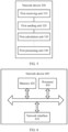
- FIG 6 is a schematic block diagram of a network device 400 for measuring a delay according to an embodiment of this application.
- the network device 400 is a first network device.
- the network device 400 includes a network interface 410, a memory 420, and a processor 430.
- the network interface includes: a receiving interface and/or a sending interface, configured to receive or send a packet.
- the memory is configured to store an instruction.
- the processor is configured to: control a first receiving interface of a media conversion module of the first network device to receive a first packet, where the first packet includes a first alignment marker AM; control a first sending interface of the media conversion module to send a second packet, where the second packet includes the first AM, and the second packet is the first packet processed by the media conversion module; calculate a time interval T 1 between a time at which the media conversion module receives the first packet including the first AM and a time at which the media conversion module sends the second packet including the first AM; control the network interface to receive a third packet by using the first receiving interface, and control the network interface to send, by using the first sending interface, the third packet processed by the media conversion module; and use the T 1 to compensate for a first timestamp at which the first network device receives or sends the third packet.
- the network device in this embodiment of this application records a time interval before and after a packet passes through the media conversion module, and uses the time interval to correct a timestamp of sending or receiving the packet. This can accurately determine the delay of the packet through internal processing of the media conversion module, and further improve synchronization performance of a 1588 protocol.
- the processor 430 may be a CPU.
- the processor 430 may further be another general-purpose processor, a digital signal processor (Digital Signal Processor, DSP), an application-specific integrated circuit (Application Specific Integrated Circuit, ASIC), a field programmable gate array (Field Programmable Gate Array, FPGA) or another programmable logic device, a discrete gate or a transistor logic device, a discrete hardware component, or the like.
- DSP Digital Signal Processor
- ASIC Application Specific Integrated Circuit
- FPGA Field Programmable Gate Array
- the general-purpose processor may be a microprocessor, or the processor may be any conventional processor or the like.
- the memory 420 may include a read-only memory and a random access memory, and provide an instruction and data to the processor 430.
- a part of the memory 420 may further include a non-volatile random access memory.
- the memory 420 may further store information about a device type.
- content in the foregoing methods can be implemented by using a hardware integrated logic circuit in the processor 430, or by using instructions in a form of software.
- the content of the method disclosed with reference to the embodiments of this application may be directly performed by a hardware processor, or may be performed by using a combination of hardware in the processor and a software module.
- a software module may be located in a mature storage medium in the art, such as a random access memory, a flash memory, a read-only memory, a programmable read-only memory, an electrically erasable programmable memory, a register, or the like.
- the storage medium is located in the memory 420, and the processor 430 reads information in the memory 420 and completes the content in the foregoing methods in combination with hardware of the processor 430. To avoid repetition, details are not described herein again.
- a first calculation unit, a second calculation unit, a third calculation unit, a first processing unit, a second processing unit, a first obtaining unit, and a second obtaining unit in the network device 300 may be implemented by the processor 430 in FIG 6 , and sending units and receiving units in the network device 300 may be implemented by the network interface 410 in FIG 6 .
- the disclosed system, apparatus, and method may be implemented in other manners.
- the described apparatus embodiment is merely an example.
- the unit division is merely logical function division and may be other division in actual implementation.
- a plurality of units or components may be combined or integrated into another system, or some features may be ignored or not performed.
- the displayed or discussed mutual couplings or direct couplings or communication connections may be implemented by using some interfaces.
- the indirect couplings or communication connections between the apparatuses or units may be implemented in electronic, mechanical, or other forms.
- the units described as separate parts may or may not be physically separate, and parts displayed as units may or may not be physical units, may be located in one position, or may be distributed on a plurality of network units. Some or all of the units may be selected depending on actual requirements to achieve the objectives of the solutions of the embodiments.
- the functions When the functions are implemented in the form of a software functional unit and sold or used as an independent product, the functions may be stored in a computer-readable storage medium. Based on such an understanding, the technical solutions of this application essentially, or the part contributing to the prior art, or some of the technical solutions may be implemented in a form of a software product.
- the computer software product is stored in a storage medium, and includes several instructions for instructing a computer device (which may be a personal computer, a server, or a network device) to perform all or some of the steps of the methods described in the embodiments of this application.
- the foregoing storage medium includes: any medium that can store program code, such as a USB flash drive, a removable hard disk, a read-only memory (Read-Only Memory, ROM), a random access memory (Random Access Memory, RAM), a magnetic disk, or an optical disc.
- program code such as a USB flash drive, a removable hard disk, a read-only memory (Read-Only Memory, ROM), a random access memory (Random Access Memory, RAM), a magnetic disk, or an optical disc.
Landscapes
- Engineering & Computer Science (AREA)
- Computer Networks & Wireless Communication (AREA)
- Signal Processing (AREA)
- Data Exchanges In Wide-Area Networks (AREA)
- Synchronisation In Digital Transmission Systems (AREA)
Claims (14)
- Paketverarbeitungsverfahren, wobei das Verfahren durch eine erste Netzwerkvorrichtung durchgeführt wird, wobei die erste Netzwerkvorrichtung ein Medienkonvertierungsmodul und einen Dienstchip umfasst, wobei das Medienkonvertierungsmodul ein optisches Modul ist und dazu konfiguriert ist, ein von einer zweiten Netzwerkvorrichtung empfangenes Eingangssignal von einem optischen Signaltyp in einen elektrischen Signaltyp zu konvertieren und das Eingangssignal dem Dienstchip bereitzustellen, und ferner dazu konfiguriert ist, ein von dem Dienstchip empfangenes Ausgangssignal von dem elektrischen Signaltyp in den optischen Signaltyp zu konvertieren und das Signal an die zweite Netzwerkvorrichtung zu senden, und wobei der Dienstchip dazu konfiguriert ist, eine Zeitstempelung von eingehenden und ausgehenden Paketen durchzuführen, und wobei das Verfahren Folgendes umfasst:Empfangen (S110) eines ersten Pakets von der zweiten Netzwerkvorrichtung unter Verwendung einer ersten Empfangsschnittstelle des Medienkonvertierungsmoduls, wobei das erste Paket einen ersten Ausrichtungsmarker, AM (alignment marker), umfasst, wobei das erste Paket in einem ersten Datenstrom beinhaltet ist, der durch Durchführen einer Codierung der physischen Schicht an einem ersten Ethernet-Frame-Strom erlangt wird, und der erste AM periodisch eingefügt wird, nachdem die Codierung der physischen Schicht an dem ersten Ethernet-Frame-Strom durchgeführt wurde;Senden (S120) eines zweiten Pakets an den Dienstchip unter Verwendung einer ersten Sendeschnittstelle des Medienkonvertierungsmoduls, wobei das zweite Paket den ersten AM umfasst und das zweite Paket das erste Paket ist, das durch das Medienkonvertierungsmodul verarbeitet wird;Berechnen (S130) einer Empfangszeitverzögerung T1 durch die erste Netzwerkvorrichtung zwischen einem Zeitpunkt, zu dem das Medienkonvertierungsmodul das erste den ersten AM umfassende Paket empfängt, und einem Zeitpunkt, zu dem das Medienkonvertierungsmodul das zweite den ersten AM umfassende Paket sendet; undEmpfangen (S140) eines dritten Pakets unter Verwendung der ersten Empfangsschnittstelle des Medienkonvertierungsmoduls und Senden des dritten Pakets nach Verarbeiten durch das Medienkonvertierungsmodul unter Verwendung der ersten Sendeschnittstelle des Medienkonvertierungsmoduls, undBestimmen (S150) eines Zeitpunkts, zu dem die erste Netzwerkvorrichtung das dritte Paket empfängt, basierend auf der Empfangszeitverzögerung T1 und einem ersten Zeitstempel, der durch den Dienstchip generiert wird, wenn das dritte Paket empfangen wird.
- Verfahren gemäß Anspruch 1, wobei das Verfahren ferner Folgendes umfasst:Empfangen eines vierten Pakets von dem Dienstchip unter Verwendung einer zweiten Empfangsschnittstelle des Medienkonvertierungsmoduls, wobei das vierte Paket einen zweiten AM umfasst, wobei das vierte Paket in einem zweiten Datenstrom beinhaltet ist, der durch Durchführen einer Codierung der physischen Schicht an einem zweiten Ethernet-Frame-Strom erlangt wird, und der zweite AM periodisch eingefügt wird, nachdem die Codierung der physischen Schicht an dem zweiten Ethernet-Frame-Strom durchgeführt wurde;Senden eines fünften Pakets an die zweite Netzwerkvorrichtung unter Verwendung einer zweiten Sendeschnittstelle des Medienkonvertierungsmoduls, wobei das fünfte Paket den zweiten AM umfasst und das fünfte Paket das vierte Paket ist, das durch das Medienkonvertierungsmodul verarbeitet wird;Berechnen einer Sendezeitverzögerung T2 durch die erste Netzwerkvorrichtung zwischen einem Zeitpunkt, zu dem das Medienkonvertierungsmodul das vierte den zweiten AM umfassende Paket empfängt, und einem Zeitpunkt, zu dem das Medienkonvertierungsmodul das fünfte den zweiten AM umfassende Paket sendet; undEmpfangen eines sechsten Pakets unter Verwendung der zweiten Empfangsschnittstelle des Medienkonvertierungsmoduls und Senden des sechsten Pakets nach Verarbeiten durch das Medienkonvertierungsmodul an die zweite Netzwerkvorrichtung, und Bestimmen eines Zeitpunkts, zu dem die erste Netzwerkvorrichtung das sechste Paket empfängt, basierend auf der Sendezeitverzögerung T2 und einem zweiten Zeitstempel, der durch den Dienstchip generiert wird, wenn das vierte Paket gesendet wird.
- Verfahren gemäß Anspruch 1 oder 2, wobei der Schritt des Berechnens (S130) einer Empfangszeitverzögerung T1 durch die erste Netzwerkvorrichtung zwischen einem Zeitpunkt, zu dem das Medienkonvertierungsmodul das erste den ersten AM umfassende Paket empfängt, und einem Zeitpunkt, zu dem das Medienkonvertierungsmodul das zweite den ersten AM umfassende Paket sendet, Folgendes umfasst:Aufzeichnen eines ersten Zeitpunkts, wenn das erste Paket unter Verwendung der ersten Empfangsschnittstelle empfangen wird und wenn bestimmt wird, dass das erste Paket den ersten AM umfasst; Aufzeichnen eines zweiten Zeitpunkts, wenn das zweite Paket unter Verwendung der ersten Sendeschnittstelle gesendet wird und wenn bestimmt wird, dass das zweite Paket den ersten AM umfasst; undBestimmen eines Zeitintervalls zwischen dem ersten Zeitpunkt und dem zweiten Zeitpunkt als das Zeitintervall T1.
- Verfahren gemäß Anspruch 3, wobei der Schritt des Bestimmens eines Zeitintervalls zwischen dem ersten Zeitpunkt und dem zweiten Zeitpunkt als das Zeitintervall T1 Folgendes umfasst:Starten eines Zählers zu dem ersten Zeitpunkt;Anhalten des Zählers zu dem zweiten Zeitpunkt und Erlangen eines Zählwertes N, wobei N eine positive ganze Zahl ist und ein Taktzyklus des Zählers t ist; undBestimmen von N * t als das T1.
- Verfahren gemäß einem der Ansprüche 1 bis 4, wobei der Schritt des Bestimmens eines Zeitpunkts, zu dem die erste Netzwerkvorrichtung das dritte Paket empfängt, basierend auf der Empfangszeitverzögerung T1 und einem ersten Zeitstempel, der durch den Dienstchip generiert wird, wenn das dritte Paket gesendet wird, Folgendes umfasst:
Verwenden einer Differenz zwischen dem ersten Zeitstempel und dem T1 als einen Zeitpunkt, zu dem die erste Netzwerkvorrichtung das dritte Paket empfängt. - Verfahren gemäß einem der Ansprüche 2 bis 4, wobei der Schritt des Bestimmens eines Zeitpunkts, zu dem die erste Netzwerkvorrichtung das sechste Paket empfängt, basierend auf der Sendezeitverzögerung T2 und einem zweiten Zeitstempel, der durch den Dienstchip generiert wird, wenn das vierte Paket gesendet wird, Folgendes umfasst:
Verwenden einer Summe des zweiten Zeitstempels und des T2 als einen Zeitpunkt, zu dem die erste Netzwerkvorrichtung das sechste Paket an die zweite Netzwerkvorrichtung sendet. - Verfahren gemäß Anspruch 2, wobei das dritte Paket ein Synchronisierungspaket ist, das durch eine zweite Netzwerkvorrichtung an die erste Netzwerkvorrichtung gesendet wird, das Synchronisierungspaket einen dritten Zeitstempel trägt, zu dem die zweite Netzwerkvorrichtung das Synchronisierungspaket sendet, das sechste Paket ein Verzögerungsanforderungspaket ist, das durch die erste Netzwerkvorrichtung an die zweite Netzwerkvorrichtung gesendet wird, die zweite Netzwerkvorrichtung eine Mastervorrichtung der ersten Netzwerkvorrichtung ist, die erste Netzwerkvorrichtung eine Slavevorrichtung der zweiten Netzwerkvorrichtung ist, und das Verfahren ferner Folgendes umfasst:Erlangen eines Zeitpunkts t1 durch die erste Netzwerkvorrichtung aus dem Synchronisierungspaket, zu dem die zweite Netzwerkvorrichtung das Synchronisierungspaket sendet; undVerwenden einer Differenz zwischen dem ersten Zeitstempel und dem T1 durch die erste Netzwerkvorrichtung als einen Zeitpunkt t2, zu dem die erste Netzwerkvorrichtung das Synchronisierungspaket empfängt; undVerwenden einer Summe des zweiten Zeitstempels und des T2 als einen Zeitpunkt t3 durch die erste Netzwerkvorrichtung, zu dem die erste Netzwerkvorrichtung das Verzögerungsanforderungspaket sendet; unddas Verfahren ferner Folgendes umfasst:Empfangen eines Verzögerungsantwortpakets, das durch die zweite Netzwerkvorrichtung gesendet wird, durch die erste Netzwerkvorrichtung, wobei das Verzögerungsantwortpaket einen vierten Zeitstempel trägt, zu dem die zweite Netzwerkvorrichtung das Verzögerungsantwortpaket empfängt;Erlangen eines Zeitpunkts t4 durch die erste Netzwerkvorrichtung aus dem Verzögerungsantwortpaket, zu dem die zweite Netzwerkvorrichtung das Verzögerungsantwortpaket empfängt; undBerechnen eines Zeitversatzes zwischen der ersten Netzwerkvorrichtung und der zweiten Netzwerkvorrichtung basierend auf dem t2, dem t2, dem t3 und dem t4 durch die erste Netzwerkvorrichtung.
- Erste Netzwerkvorrichtung, umfassend ein Medienkonvertierungsmodul und einen Dienstchip, wobei das Medienkonvertierungsmodul ein optisches Modul ist und dazu konfiguriert ist, ein von einer zweiten Netzwerkvorrichtung empfangenes Eingangssignal von einem optischen Signaltyp in einen elektrischen Signaltyp zu konvertieren und das Eingangssignal dem Dienstchip bereitzustellen, und ferner dazu konfiguriert ist, ein von dem Dienst empfangenes Ausgangssignal von dem elektrischen Signaltyp in den optischen Signaltyp zu konvertieren und das Signal an die zweite Netzwerkvorrichtung zu senden, und wobei der Dienstchip dazu konfiguriert ist, eine Zeitstempelung von eingehenden und ausgehenden Paketen durchzuführen, und wobei die Netzwerkvorrichtung einen Speicher und einen Prozessor umfasst, wobei der Speicher dazu konfiguriert ist, einen Satz von Anweisungen zu speichern, die, wenn sie von dem Prozessor ausgeführt werden, die erste Netzwerkvorrichtung veranlassen, die folgenden Schritte durchzuführen:Empfangen (S110) eines ersten Pakets von der zweiten Netzwerkvorrichtung unter Verwendung einer ersten Empfangsschnittstelle des Medienkonvertierungsmoduls, wobei das erste Paket einen ersten Ausrichtungsmarker, AM, umfasst, wobei das erste Paket in einem ersten Datenstrom beinhaltet ist, der durch Durchführen einer Codierung der physischen Schicht an einem ersten Ethernet-Frame-Strom erlangt wird, und der erste AM periodisch eingefügt wird, nachdem die Codierung der physischen Schicht an dem ersten Ethernet-Frame-Strom durchgeführt wurde;Senden (S120) eines zweiten Pakets an den Dienstchip unter Verwendung einer ersten Sendeschnittstelle des Medienkonvertierungsmoduls, wobei das zweite Paket den ersten AM umfasst und das zweite Paket das erste Paket ist, das durch das Medienkonvertierungsmodul verarbeitet wird;Berechnen (S130) einer Empfangszeitverzögerung T1 zwischen einem Zeitpunkt, zu dem das Medienkonvertierungsmodul das erste den ersten AM umfassende Paket empfängt, und einem Zeitpunkt, zu dem das Medienkonvertierungsmodul das zweite den ersten AM umfassende Paket sendet; undEmpfangen (S140) eines dritten Pakets unter Verwendung der ersten Empfangsschnittstelle des Medienkonvertierungsmoduls und Senden des dritten Pakets nach Verarbeiten durch das Medienkonvertierungsmodul unter Verwendung der ersten Sendeschnittstelle des Medienkonvertierungsmoduls, undBestimmen (S150) eines Zeitpunkts, zu dem die erste Netzwerkvorrichtung das dritte Paket empfängt, basierend auf der Empfangszeitverzögerung T1 und einem ersten Zeitstempel, der durch den Dienstchip generiert wird, wenn das dritte Paket gesendet wird.
- Erste Netzwerkvorrichtung gemäß Anspruch 8, wobei der Prozessor ferner veranlasst wird, die folgenden Schritte durchzuführen:Empfangen eines vierten Pakets von dem Dienstchip unter Verwendung einer zweiten Empfangsschnittstelle des Medienkonvertierungsmoduls, wobei das vierte Paket einen zweiten AM umfasst, wobei das vierte Paket in einem zweiten Datenstrom beinhaltet ist, der durch Durchführen einer Codierung der physischen Schicht an einem zweiten Ethernet-Frame-Strom erlangt wird, und der zweite AM periodisch eingefügt wird, nachdem die Codierung der physischen Schicht an dem zweiten Ethernet-Frame-Strom durchgeführt wurde;Senden eines fünften Pakets an die zweite Netzwerkvorrichtung unter Verwendung einer zweiten Sendeschnittstelle des Medienkonvertierungsmoduls, wobei das fünfte Paket den zweiten AM umfasst und das fünfte Paket das vierte Paket ist, das durch das Medienkonvertierungsmodul verarbeitet wird;Berechnen einer Sendezeitverzögerung T2 zwischen einem Zeitpunkt, zu dem das Medienkonvertierungsmodul das vierte den zweiten AM umfassende Paket empfängt, und einem Zeitpunkt, zu dem das Medienkonvertierungsmodul das fünfte den zweiten AM umfassende Paket sendet; undEmpfangen eines sechsten Pakets unter Verwendung der zweiten Empfangsschnittstelle des Medienkonvertierungsmoduls und Senden des sechsten Pakets nach Verarbeiten durch das Medienkonvertierungsmodul an die zweite Netzwerkvorrichtung, und Bestimmen eines Zeitpunkts, zu dem die erste Netzwerkvorrichtung das sechste Paket empfängt, basierend auf der Sendezeitverzögerung T2 und einem zweiten Zeitstempel, der durch den Dienstchip generiert wird, wenn das vierte Paket gesendet wird.
- Erste Netzwerkvorrichtung gemäß Anspruch 8, wobei der Schritt des Berechnens (S130) einer Empfangszeitverzögerung T1 zwischen einem Zeitpunkt, zu dem das Medienkonvertierungsmodul das erste den ersten AM umfassende Paket empfängt, und einem Zeitpunkt, zu dem das Medienkonvertierungsmodul das zweite den ersten AM umfassende Paket sendet, Folgendes umfasst:Aufzeichnen eines ersten Zeitpunkts, wenn das erste Paket unter Verwendung der ersten Empfangsschnittstelle empfangen wird und wenn bestimmt wird, dass das erste Paket den ersten AM umfasst; Aufzeichnen eines zweiten Zeitpunkts, wenn das zweite Paket unter Verwendung der ersten Sendeschnittstelle gesendet wird und wenn bestimmt wird, dass das zweite Paket den ersten AM umfasst; undBestimmen eines Zeitintervalls zwischen dem ersten Zeitpunkt und dem zweiten Zeitpunkt als das Zeitintervall T1.
- Erste Netzwerkvorrichtung gemäß Anspruch 10, wobei der Schritt des Bestimmens eines Zeitintervalls zwischen dem ersten Zeitpunkt und dem zweiten Zeitpunkt als das Zeitintervall T1 Folgendes umfasst:Starten eines Zählers zu dem ersten Zeitpunkt;Anhalten des Zählers zu dem zweiten Zeitpunkt und Erlangen eines Zählwertes N, wobei N eine positive ganze Zahl ist und ein Taktzyklus des Zählers t ist; undBestimmen von N * t als das T1.
- Erste Netzwerkvorrichtung gemäß einem der Ansprüche 8 bis 11, wobei der Schritt des Bestimmens eines Zeitpunkts, zu dem die erste Netzwerkvorrichtung das dritte Paket empfängt, basierend auf der Empfangszeitverzögerung T1 und einem ersten Zeitstempel, der durch den Dienstchip generiert wird, wenn das dritte Paket empfangen wird, Folgendes umfasst:
Verwenden einer Differenz zwischen dem ersten Zeitstempel und dem T1 als einen Zeitpunkt, zu dem die erste Netzwerkvorrichtung das dritte Paket empfängt. - Erste Netzwerkvorrichtung gemäß einem der Ansprüche 9 bis 12, wobei der Schritt des Bestimmens eines Zeitpunkts, zu dem die erste Netzwerkvorrichtung das sechste Paket empfängt, basierend auf der Sendezeitverzögerung T2 und einem zweiten Zeitstempel, der durch den Dienstchip generiert wird, wenn das vierte Paket gesendet wird, Folgendes umfasst:
Verwenden einer Summe des zweiten Zeitstempels und des T2 als einen Zeitpunkt, zu dem die erste Netzwerkvorrichtung das sechste Paket an die zweite Netzwerkvorrichtung sendet. - Erste Netzwerkvorrichtung gemäß einem der Ansprüche 8 bis 13, wobei das dritte Paket ein Synchronisierungspaket ist, das durch eine zweite Netzwerkvorrichtung an die erste Netzwerkvorrichtung gesendet wird, das Synchronisierungspaket einen dritten Zeitstempel trägt, zu dem die zweite Netzwerkvorrichtung das Synchronisierungspaket sendet, das sechste Paket ein Verzögerungsanforderungspaket ist, das durch die erste Netzwerkvorrichtung an die zweite Netzwerkvorrichtung gesendet wird, die zweite Netzwerkvorrichtung eine Mastervorrichtung der ersten Netzwerkvorrichtung ist, die erste Netzwerkvorrichtung eine Slavevorrichtung der zweiten Netzwerkvorrichtung ist, und wobei der Prozessor ferner veranlasst wird, die folgenden Schritte durchzuführen:Erlangen eines Zeitpunkts t1 aus dem Synchronisierungspaket, zu dem die zweite Netzwerkvorrichtung das Synchronisierungspaket sendet; undVerwenden einer Differenz zwischen dem ersten Zeitstempel und dem T1 als einen Zeitpunkt t2, zu dem die erste Netzwerkvorrichtung das Synchronisierungspaket empfängt; undVerwenden einer Summe des zweiten Zeitstempels und des T2 als einen Zeitpunkt t3, zu dem die erste Netzwerkvorrichtung das Verzögerungsanforderungspaket sendet; unddie erste Netzwerkvorrichtung ferner zu Folgendem konfiguriert ist:Empfangen eines Verzögerungsantwortpakets, das durch die zweite Netzwerkvorrichtung gesendet wird, wobei das Verzögerungsantwortpaket einen vierten Zeitstempel trägt, zu dem die zweite Netzwerkvorrichtung das Verzögerungsantwortpaket empfängt;Erlangen eines Zeitpunkts t4 aus dem Verzögerungsantwortpaket, zu dem die zweite Netzwerkvorrichtung das Verzögerungsantwortpaket empfängt; undBerechnen eines Zeitversatzes zwischen der ersten Netzwerkvorrichtung und der zweiten Netzwerkvorrichtung basierend auf dem t1, dem t2, dem t3 und dem t4.
Applications Claiming Priority (1)
| Application Number | Priority Date | Filing Date | Title |
|---|---|---|---|
| PCT/CN2017/098685 WO2019036943A1 (zh) | 2017-08-23 | 2017-08-23 | 一种报文处理的方法和网络设备 |
Publications (3)
| Publication Number | Publication Date |
|---|---|
| EP3664375A1 EP3664375A1 (de) | 2020-06-10 |
| EP3664375A4 EP3664375A4 (de) | 2020-08-12 |
| EP3664375B1 true EP3664375B1 (de) | 2024-10-09 |
Family
ID=65438374
Family Applications (1)
| Application Number | Title | Priority Date | Filing Date |
|---|---|---|---|
| EP17922213.8A Active EP3664375B1 (de) | 2017-08-23 | 2017-08-23 | Paketverarbeitungsverfahren und netzwerkvorrichtung |
Country Status (4)
| Country | Link |
|---|---|
| US (2) | US11245483B2 (de) |
| EP (1) | EP3664375B1 (de) |
| CN (2) | CN109699199B (de) |
| WO (1) | WO2019036943A1 (de) |
Families Citing this family (17)
| Publication number | Priority date | Publication date | Assignee | Title |
|---|---|---|---|---|
| CN108023723B (zh) * | 2016-11-04 | 2021-07-09 | 华为技术有限公司 | 频率同步的方法以及从时钟 |
| CN111464252B (zh) * | 2019-01-22 | 2023-01-06 | 华为技术有限公司 | 通信方法和光模块 |
| CN112217588B (zh) * | 2019-07-10 | 2021-11-16 | 烽火通信科技股份有限公司 | 时间戳抖动补偿方法及系统 |
| WO2021031153A1 (zh) * | 2019-08-21 | 2021-02-25 | 华为技术有限公司 | 一种数据处理的设备以及系统 |
| CN112532279B (zh) | 2019-09-17 | 2023-10-20 | 华为技术有限公司 | 获取数据传输时间的方法、装置、系统及存储介质 |
| EP4044466B1 (de) * | 2019-10-22 | 2025-02-19 | Huawei Technologies Co., Ltd. | Synchronisationsverfahren und -vorrichtung |
| CN112994820B (zh) * | 2019-12-16 | 2023-04-18 | 华为技术有限公司 | 一种光纤链路检测方法及装置 |
| CN113839730B (zh) * | 2020-06-24 | 2025-02-18 | 中兴通讯股份有限公司 | 时间同步方法、网络设备及存储介质 |
| US11599090B2 (en) * | 2020-09-30 | 2023-03-07 | Rockwell Automation Technologies, Inc. | System and method of network synchronized time in safety applications |
| CN114499727B (zh) * | 2020-10-27 | 2025-07-29 | 南京中兴新软件有限责任公司 | 时间校准方法、通信设备和计算机可读介质 |
| CN116746126A (zh) * | 2021-03-29 | 2023-09-12 | 华为技术有限公司 | 测量方法及网络设备 |
| CN114245411A (zh) * | 2021-11-08 | 2022-03-25 | 深圳震有科技股份有限公司 | 报文延时时间的测试方法、装置、终端设备及存储介质 |
| WO2023085986A1 (en) * | 2021-11-11 | 2023-05-19 | Telefonaktiebolaget Lm Ericsson (Publ) | Methods for clock synchronization between network nodes using ethernet and transmitting forward error correction (fec) markers, and node |
| US12199745B2 (en) * | 2022-01-28 | 2025-01-14 | Avago Technologies International Sales Pte. Limited | Time synchronization based on lookup table |
| US12355553B2 (en) | 2022-03-30 | 2025-07-08 | Rockwell Automation Technologies, Inc. | Diagnostic system and method for network synchronized time in safety applications |
| CN115560762B (zh) * | 2022-09-21 | 2026-03-20 | 小米汽车科技有限公司 | 车载控制器、车辆控制方法、车辆及芯片 |
| WO2025144817A1 (en) * | 2023-12-28 | 2025-07-03 | Marvell Semiconductor, Inc. | Latency measurement in a communication device |
Family Cites Families (17)
| Publication number | Priority date | Publication date | Assignee | Title |
|---|---|---|---|---|
| WO2005050463A1 (en) * | 2003-11-19 | 2005-06-02 | Nimcat Networks Inc. | Time and data synchronization between network devices |
| WO2005077063A2 (en) * | 2004-02-09 | 2005-08-25 | Semtech Corporation | Method and apparatus for aligning time references when separated by an unreliable data packet network |
| EP2025104A4 (de) * | 2006-05-19 | 2013-04-03 | Symmetricom Inc | Netzwerk-zeitprotokoll-präzisionszeitstempeldienst |
| US8295312B2 (en) * | 2009-06-08 | 2012-10-23 | Broadcom Corporation | Method and system for compensated time stamping for time-sensitive network communications |
| WO2011151913A1 (ja) * | 2010-06-03 | 2011-12-08 | 株式会社日立製作所 | 光通信システム、光受信器、光トランスポンダ、波長多重光通信システム、波長多重受信装置及び波長多重光トランスポンダ |
| CN102447745B (zh) * | 2012-01-11 | 2018-10-26 | 南京中兴新软件有限责任公司 | Tc设备上的报文驻留时间的处理方法及装置 |
| WO2012092892A2 (zh) * | 2012-02-01 | 2012-07-12 | 华为技术有限公司 | 时间同步方法和设备及系统 |
| CN103929293B (zh) * | 2013-01-15 | 2017-02-22 | 电子科技大学 | 非对称延迟的时间同步方法及系统 |
| CN104113517A (zh) * | 2013-04-22 | 2014-10-22 | 华为技术有限公司 | 时间戳生成方法、装置及系统 |
| EP3295726B1 (de) * | 2015-05-14 | 2020-06-24 | Telefonaktiebolaget LM Ericsson (publ) | Methode und system zur synchronisierung von knoten in einem drahtlosen netzwerk |
| US9602271B2 (en) * | 2015-06-01 | 2017-03-21 | Globalfoundries Inc. | Sub-nanosecond distributed clock synchronization using alignment marker in ethernet IEEE 1588 protocol |
| CN105188128B (zh) * | 2015-08-21 | 2018-10-16 | 北京北方烽火科技有限公司 | 一种无线授时和空口同步方法、基站、通讯设备及系统 |
| CN105515908A (zh) * | 2015-12-10 | 2016-04-20 | 中国航空工业集团公司西安航空计算技术研究所 | Afdx光电转换时延测试方法 |
| CN105610535B (zh) * | 2015-12-25 | 2018-06-29 | 南方电网科学研究院有限责任公司 | Epon接入业务的往返时间同步方法和系统 |
| CN106788836B (zh) * | 2016-04-06 | 2019-09-06 | 新华三技术有限公司 | 一种系统时间的同步方法及装置 |
| US10341083B2 (en) * | 2016-09-09 | 2019-07-02 | Huawei Technologies Co., Ltd. | System and methods for network synchronization |
| US10135601B1 (en) * | 2017-05-16 | 2018-11-20 | Disney Enterprises, Inc. | Providing common point of control and configuration in IP-based timing systems |
-
2017
- 2017-08-23 CN CN201780003881.4A patent/CN109699199B/zh active Active
- 2017-08-23 CN CN202110542190.XA patent/CN113612564B/zh active Active
- 2017-08-23 EP EP17922213.8A patent/EP3664375B1/de active Active
- 2017-08-23 WO PCT/CN2017/098685 patent/WO2019036943A1/zh not_active Ceased
-
2020
- 2020-02-21 US US16/797,225 patent/US11245483B2/en active Active
-
2022
- 2022-01-14 US US17/576,423 patent/US11588568B2/en active Active
Non-Patent Citations (1)
| Title |
|---|
| TEXAS INSTRUMENTS: "AN-1507 DP83848 and DP83849 100Mb Data Latency", 1 April 2013 (2013-04-01), Dallas, Texas, pages 1 - 16, XP055709991, Retrieved from the Internet <URL:https://www.ti.com/lit/an/snla084b/snla084b.pdf> [retrieved on 20200630] * |
Also Published As
| Publication number | Publication date |
|---|---|
| WO2019036943A1 (zh) | 2019-02-28 |
| CN113612564A (zh) | 2021-11-05 |
| CN109699199A (zh) | 2019-04-30 |
| US20220140929A1 (en) | 2022-05-05 |
| US11588568B2 (en) | 2023-02-21 |
| CN113612564B (zh) | 2024-06-14 |
| US11245483B2 (en) | 2022-02-08 |
| EP3664375A1 (de) | 2020-06-10 |
| US20200195363A1 (en) | 2020-06-18 |
| EP3664375A4 (de) | 2020-08-12 |
| CN109699199B (zh) | 2021-05-14 |
Similar Documents
| Publication | Publication Date | Title |
|---|---|---|
| EP3664375B1 (de) | Paketverarbeitungsverfahren und netzwerkvorrichtung | |
| US10313103B1 (en) | Systems and methods for precise time synchronization with optical modules | |
| EP2381622B1 (de) | Aktualisierung einer kumulativen Verweilzeit eines Pakets in einem paketvermittelten Kommunikationsnetzwerk | |
| US8934506B2 (en) | Apparatus and method for estimating time stamp | |
| US9256247B2 (en) | Method and apparatus for communicating time information between time aware devices | |
| US20120275501A1 (en) | Pluggable synchronization clocks, networks, systems and methods related thereto | |
| CN102843620B (zh) | 一种实现时间同步传送的otn设备及方法 | |
| CN101827098A (zh) | 时间同步的处理方法及装置 | |
| CN101447861A (zh) | Ieee 1588时间同步系统及其实现方法 | |
| WO2012151808A1 (zh) | 基于精确时钟协议提高同步精度的方法及系统 | |
| WO2019174554A1 (zh) | 一种补偿时延的方法和设备 | |
| CN105959076A (zh) | 使无源光网络具备支持时间同步能力的装置与方法 | |
| CN105027489B (zh) | 精确时钟协议同步方法和节点 | |
| WO2023213080A1 (zh) | 基于fpga实现网络节点时间同步的方法 | |
| US9112603B2 (en) | Apparatus and method for measuring a delay | |
| JP2013501433A (ja) | 光伝送網が時刻同期プロトコルをキャリングする方法及びシステム | |
| US12395309B2 (en) | Timestamping for multiple synchronization domains in a network device | |
| CN108155982A (zh) | 一种时间戳处理方法及设备 | |
| CN111543019B (zh) | 利用光学模块进行精确时间同步的系统和方法 | |
| CN102957489B (zh) | 时钟同步方法、主从时钟实体 | |
| EP3518456A1 (de) | Drahtlose vorrichtung, verarbeitungsverfahren für drahtlose vorrichtung und programm | |
| CN107888315A (zh) | 一种时间同步方法 | |
| CN101471740B (zh) | 测量sdh网元传输时延及时钟同步的方法、装置和系统 | |
| TWI847415B (zh) | 網路裝置與網路封包處理方法 | |
| US10374735B2 (en) | Communication system, communication system control method, transmission device, and reception device |
Legal Events
| Date | Code | Title | Description |
|---|---|---|---|
| STAA | Information on the status of an ep patent application or granted ep patent |
Free format text: STATUS: THE INTERNATIONAL PUBLICATION HAS BEEN MADE |
|
| PUAI | Public reference made under article 153(3) epc to a published international application that has entered the european phase |
Free format text: ORIGINAL CODE: 0009012 |
|
| STAA | Information on the status of an ep patent application or granted ep patent |
Free format text: STATUS: REQUEST FOR EXAMINATION WAS MADE |
|
| 17P | Request for examination filed |
Effective date: 20200304 |
|
| AK | Designated contracting states |
Kind code of ref document: A1 Designated state(s): AL AT BE BG CH CY CZ DE DK EE ES FI FR GB GR HR HU IE IS IT LI LT LU LV MC MK MT NL NO PL PT RO RS SE SI SK SM TR |
|
| AX | Request for extension of the european patent |
Extension state: BA ME |
|
| REG | Reference to a national code |
Ref legal event code: R079 Free format text: PREVIOUS MAIN CLASS: H04L0012260000 Ipc: H04J0003060000 Ref country code: DE Ref document number: 602017085458 Country of ref document: DE |
|
| A4 | Supplementary search report drawn up and despatched |
Effective date: 20200709 |
|
| RIC1 | Information provided on ipc code assigned before grant |
Ipc: H04J 3/06 20060101AFI20200704BHEP |
|
| DAV | Request for validation of the european patent (deleted) | ||
| DAX | Request for extension of the european patent (deleted) | ||
| STAA | Information on the status of an ep patent application or granted ep patent |
Free format text: STATUS: EXAMINATION IS IN PROGRESS |
|
| 17Q | First examination report despatched |
Effective date: 20230710 |
|
| GRAP | Despatch of communication of intention to grant a patent |
Free format text: ORIGINAL CODE: EPIDOSNIGR1 |
|
| STAA | Information on the status of an ep patent application or granted ep patent |
Free format text: STATUS: GRANT OF PATENT IS INTENDED |
|
| INTG | Intention to grant announced |
Effective date: 20240411 |
|
| GRAS | Grant fee paid |
Free format text: ORIGINAL CODE: EPIDOSNIGR3 |
|
| GRAA | (expected) grant |
Free format text: ORIGINAL CODE: 0009210 |
|
| STAA | Information on the status of an ep patent application or granted ep patent |
Free format text: STATUS: THE PATENT HAS BEEN GRANTED |
|
| AK | Designated contracting states |
Kind code of ref document: B1 Designated state(s): AL AT BE BG CH CY CZ DE DK EE ES FI FR GB GR HR HU IE IS IT LI LT LU LV MC MK MT NL NO PL PT RO RS SE SI SK SM TR |
|
| REG | Reference to a national code |
Ref country code: CH Ref legal event code: EP |
|
| REG | Reference to a national code |
Ref country code: DE Ref legal event code: R096 Ref document number: 602017085458 Country of ref document: DE |
|
| REG | Reference to a national code |
Ref country code: IE Ref legal event code: FG4D |
|
| REG | Reference to a national code |
Ref country code: LT Ref legal event code: MG9D |
|
| REG | Reference to a national code |
Ref country code: NL Ref legal event code: MP Effective date: 20241009 |
|
| REG | Reference to a national code |
Ref country code: AT Ref legal event code: MK05 Ref document number: 1731730 Country of ref document: AT Kind code of ref document: T Effective date: 20241009 |
|
| PG25 | Lapsed in a contracting state [announced via postgrant information from national office to epo] |
Ref country code: NL Free format text: LAPSE BECAUSE OF FAILURE TO SUBMIT A TRANSLATION OF THE DESCRIPTION OR TO PAY THE FEE WITHIN THE PRESCRIBED TIME-LIMIT Effective date: 20241009 |
|
| PG25 | Lapsed in a contracting state [announced via postgrant information from national office to epo] |
Ref country code: NL Free format text: LAPSE BECAUSE OF FAILURE TO SUBMIT A TRANSLATION OF THE DESCRIPTION OR TO PAY THE FEE WITHIN THE PRESCRIBED TIME-LIMIT Effective date: 20241009 |
|
| PG25 | Lapsed in a contracting state [announced via postgrant information from national office to epo] |
Ref country code: PT Free format text: LAPSE BECAUSE OF FAILURE TO SUBMIT A TRANSLATION OF THE DESCRIPTION OR TO PAY THE FEE WITHIN THE PRESCRIBED TIME-LIMIT Effective date: 20250210 Ref country code: HR Free format text: LAPSE BECAUSE OF FAILURE TO SUBMIT A TRANSLATION OF THE DESCRIPTION OR TO PAY THE FEE WITHIN THE PRESCRIBED TIME-LIMIT Effective date: 20241009 Ref country code: IS Free format text: LAPSE BECAUSE OF FAILURE TO SUBMIT A TRANSLATION OF THE DESCRIPTION OR TO PAY THE FEE WITHIN THE PRESCRIBED TIME-LIMIT Effective date: 20250209 |
|
| PG25 | Lapsed in a contracting state [announced via postgrant information from national office to epo] |
Ref country code: FI Free format text: LAPSE BECAUSE OF FAILURE TO SUBMIT A TRANSLATION OF THE DESCRIPTION OR TO PAY THE FEE WITHIN THE PRESCRIBED TIME-LIMIT Effective date: 20241009 |
|
| PG25 | Lapsed in a contracting state [announced via postgrant information from national office to epo] |
Ref country code: BG Free format text: LAPSE BECAUSE OF FAILURE TO SUBMIT A TRANSLATION OF THE DESCRIPTION OR TO PAY THE FEE WITHIN THE PRESCRIBED TIME-LIMIT Effective date: 20241009 |
|
| PG25 | Lapsed in a contracting state [announced via postgrant information from national office to epo] |
Ref country code: ES Free format text: LAPSE BECAUSE OF FAILURE TO SUBMIT A TRANSLATION OF THE DESCRIPTION OR TO PAY THE FEE WITHIN THE PRESCRIBED TIME-LIMIT Effective date: 20241009 |
|
| PG25 | Lapsed in a contracting state [announced via postgrant information from national office to epo] |
Ref country code: NO Free format text: LAPSE BECAUSE OF FAILURE TO SUBMIT A TRANSLATION OF THE DESCRIPTION OR TO PAY THE FEE WITHIN THE PRESCRIBED TIME-LIMIT Effective date: 20250109 |
|
| PG25 | Lapsed in a contracting state [announced via postgrant information from national office to epo] |
Ref country code: GR Free format text: LAPSE BECAUSE OF FAILURE TO SUBMIT A TRANSLATION OF THE DESCRIPTION OR TO PAY THE FEE WITHIN THE PRESCRIBED TIME-LIMIT Effective date: 20250110 Ref country code: LV Free format text: LAPSE BECAUSE OF FAILURE TO SUBMIT A TRANSLATION OF THE DESCRIPTION OR TO PAY THE FEE WITHIN THE PRESCRIBED TIME-LIMIT Effective date: 20241009 Ref country code: AT Free format text: LAPSE BECAUSE OF FAILURE TO SUBMIT A TRANSLATION OF THE DESCRIPTION OR TO PAY THE FEE WITHIN THE PRESCRIBED TIME-LIMIT Effective date: 20241009 |
|
| PG25 | Lapsed in a contracting state [announced via postgrant information from national office to epo] |
Ref country code: PL Free format text: LAPSE BECAUSE OF FAILURE TO SUBMIT A TRANSLATION OF THE DESCRIPTION OR TO PAY THE FEE WITHIN THE PRESCRIBED TIME-LIMIT Effective date: 20241009 |
|
| PG25 | Lapsed in a contracting state [announced via postgrant information from national office to epo] |
Ref country code: RS Free format text: LAPSE BECAUSE OF FAILURE TO SUBMIT A TRANSLATION OF THE DESCRIPTION OR TO PAY THE FEE WITHIN THE PRESCRIBED TIME-LIMIT Effective date: 20250109 |
|
| PG25 | Lapsed in a contracting state [announced via postgrant information from national office to epo] |
Ref country code: SM Free format text: LAPSE BECAUSE OF FAILURE TO SUBMIT A TRANSLATION OF THE DESCRIPTION OR TO PAY THE FEE WITHIN THE PRESCRIBED TIME-LIMIT Effective date: 20241009 |
|
| PG25 | Lapsed in a contracting state [announced via postgrant information from national office to epo] |
Ref country code: DK Free format text: LAPSE BECAUSE OF FAILURE TO SUBMIT A TRANSLATION OF THE DESCRIPTION OR TO PAY THE FEE WITHIN THE PRESCRIBED TIME-LIMIT Effective date: 20241009 |
|
| REG | Reference to a national code |
Ref country code: DE Ref legal event code: R097 Ref document number: 602017085458 Country of ref document: DE |
|
| PG25 | Lapsed in a contracting state [announced via postgrant information from national office to epo] |
Ref country code: EE Free format text: LAPSE BECAUSE OF FAILURE TO SUBMIT A TRANSLATION OF THE DESCRIPTION OR TO PAY THE FEE WITHIN THE PRESCRIBED TIME-LIMIT Effective date: 20241009 |
|
| PG25 | Lapsed in a contracting state [announced via postgrant information from national office to epo] |
Ref country code: RO Free format text: LAPSE BECAUSE OF FAILURE TO SUBMIT A TRANSLATION OF THE DESCRIPTION OR TO PAY THE FEE WITHIN THE PRESCRIBED TIME-LIMIT Effective date: 20241009 |
|
| PG25 | Lapsed in a contracting state [announced via postgrant information from national office to epo] |
Ref country code: SK Free format text: LAPSE BECAUSE OF FAILURE TO SUBMIT A TRANSLATION OF THE DESCRIPTION OR TO PAY THE FEE WITHIN THE PRESCRIBED TIME-LIMIT Effective date: 20241009 |
|
| PG25 | Lapsed in a contracting state [announced via postgrant information from national office to epo] |
Ref country code: CZ Free format text: LAPSE BECAUSE OF FAILURE TO SUBMIT A TRANSLATION OF THE DESCRIPTION OR TO PAY THE FEE WITHIN THE PRESCRIBED TIME-LIMIT Effective date: 20241009 |
|
| PG25 | Lapsed in a contracting state [announced via postgrant information from national office to epo] |
Ref country code: IT Free format text: LAPSE BECAUSE OF FAILURE TO SUBMIT A TRANSLATION OF THE DESCRIPTION OR TO PAY THE FEE WITHIN THE PRESCRIBED TIME-LIMIT Effective date: 20241009 |
|
| PLBE | No opposition filed within time limit |
Free format text: ORIGINAL CODE: 0009261 |
|
| STAA | Information on the status of an ep patent application or granted ep patent |
Free format text: STATUS: NO OPPOSITION FILED WITHIN TIME LIMIT |
|
| PG25 | Lapsed in a contracting state [announced via postgrant information from national office to epo] |
Ref country code: SE Free format text: LAPSE BECAUSE OF FAILURE TO SUBMIT A TRANSLATION OF THE DESCRIPTION OR TO PAY THE FEE WITHIN THE PRESCRIBED TIME-LIMIT Effective date: 20241009 |
|
| 26N | No opposition filed |
Effective date: 20250710 |
|
| PGFP | Annual fee paid to national office [announced via postgrant information from national office to epo] |
Ref country code: DE Payment date: 20250702 Year of fee payment: 9 |
|
| REG | Reference to a national code |
Ref country code: CH Ref legal event code: H13 Free format text: ST27 STATUS EVENT CODE: U-0-0-H10-H13 (AS PROVIDED BY THE NATIONAL OFFICE) Effective date: 20260324 |
|
| PG25 | Lapsed in a contracting state [announced via postgrant information from national office to epo] |
Ref country code: MC Free format text: LAPSE BECAUSE OF FAILURE TO SUBMIT A TRANSLATION OF THE DESCRIPTION OR TO PAY THE FEE WITHIN THE PRESCRIBED TIME-LIMIT Effective date: 20241009 |
|
| PG25 | Lapsed in a contracting state [announced via postgrant information from national office to epo] |
Ref country code: LU Free format text: LAPSE BECAUSE OF NON-PAYMENT OF DUE FEES Effective date: 20250823 |