EP3664191A1 - Electrode assembly comprising plastic member applied to electrode tab-lead joint part and secondary battery containing same - Google Patents
Electrode assembly comprising plastic member applied to electrode tab-lead joint part and secondary battery containing same Download PDFInfo
- Publication number
- EP3664191A1 EP3664191A1 EP18899172.3A EP18899172A EP3664191A1 EP 3664191 A1 EP3664191 A1 EP 3664191A1 EP 18899172 A EP18899172 A EP 18899172A EP 3664191 A1 EP3664191 A1 EP 3664191A1
- Authority
- EP
- European Patent Office
- Prior art keywords
- electrode
- electrode assembly
- tabs
- coupled
- electrode tabs
- Prior art date
- Legal status (The legal status is an assumption and is not a legal conclusion. Google has not performed a legal analysis and makes no representation as to the accuracy of the status listed.)
- Pending
Links
Images



Classifications
-
- H—ELECTRICITY
- H01—ELECTRIC ELEMENTS
- H01M—PROCESSES OR MEANS, e.g. BATTERIES, FOR THE DIRECT CONVERSION OF CHEMICAL ENERGY INTO ELECTRICAL ENERGY
- H01M50/00—Constructional details or processes of manufacture of the non-active parts of electrochemical cells other than fuel cells, e.g. hybrid cells
- H01M50/10—Primary casings; Jackets or wrappings
- H01M50/172—Arrangements of electric connectors penetrating the casing
- H01M50/174—Arrangements of electric connectors penetrating the casing adapted for the shape of the cells
- H01M50/178—Arrangements of electric connectors penetrating the casing adapted for the shape of the cells for pouch or flexible bag cells
-
- B—PERFORMING OPERATIONS; TRANSPORTING
- B23—MACHINE TOOLS; METAL-WORKING NOT OTHERWISE PROVIDED FOR
- B23K—SOLDERING OR UNSOLDERING; WELDING; CLADDING OR PLATING BY SOLDERING OR WELDING; CUTTING BY APPLYING HEAT LOCALLY, e.g. FLAME CUTTING; WORKING BY LASER BEAM
- B23K20/00—Non-electric welding by applying impact or other pressure, with or without the application of heat, e.g. cladding or plating
- B23K20/10—Non-electric welding by applying impact or other pressure, with or without the application of heat, e.g. cladding or plating making use of vibrations, e.g. ultrasonic welding
-
- H—ELECTRICITY
- H01—ELECTRIC ELEMENTS
- H01M—PROCESSES OR MEANS, e.g. BATTERIES, FOR THE DIRECT CONVERSION OF CHEMICAL ENERGY INTO ELECTRICAL ENERGY
- H01M10/00—Secondary cells; Manufacture thereof
- H01M10/04—Construction or manufacture in general
-
- H—ELECTRICITY
- H01—ELECTRIC ELEMENTS
- H01M—PROCESSES OR MEANS, e.g. BATTERIES, FOR THE DIRECT CONVERSION OF CHEMICAL ENERGY INTO ELECTRICAL ENERGY
- H01M10/00—Secondary cells; Manufacture thereof
- H01M10/04—Construction or manufacture in general
- H01M10/0413—Large-sized flat cells or batteries for motive or stationary systems with plate-like electrodes
-
- H—ELECTRICITY
- H01—ELECTRIC ELEMENTS
- H01M—PROCESSES OR MEANS, e.g. BATTERIES, FOR THE DIRECT CONVERSION OF CHEMICAL ENERGY INTO ELECTRICAL ENERGY
- H01M10/00—Secondary cells; Manufacture thereof
- H01M10/04—Construction or manufacture in general
- H01M10/0436—Small-sized flat cells or batteries for portable equipment
-
- H—ELECTRICITY
- H01—ELECTRIC ELEMENTS
- H01M—PROCESSES OR MEANS, e.g. BATTERIES, FOR THE DIRECT CONVERSION OF CHEMICAL ENERGY INTO ELECTRICAL ENERGY
- H01M10/00—Secondary cells; Manufacture thereof
- H01M10/05—Accumulators with non-aqueous electrolyte
- H01M10/058—Construction or manufacture
- H01M10/0585—Construction or manufacture of accumulators having only flat construction elements, i.e. flat positive electrodes, flat negative electrodes and flat separators
-
- H—ELECTRICITY
- H01—ELECTRIC ELEMENTS
- H01M—PROCESSES OR MEANS, e.g. BATTERIES, FOR THE DIRECT CONVERSION OF CHEMICAL ENERGY INTO ELECTRICAL ENERGY
- H01M50/00—Constructional details or processes of manufacture of the non-active parts of electrochemical cells other than fuel cells, e.g. hybrid cells
- H01M50/10—Primary casings; Jackets or wrappings
- H01M50/102—Primary casings; Jackets or wrappings characterised by their shape or physical structure
- H01M50/105—Pouches or flexible bags
-
- H—ELECTRICITY
- H01—ELECTRIC ELEMENTS
- H01M—PROCESSES OR MEANS, e.g. BATTERIES, FOR THE DIRECT CONVERSION OF CHEMICAL ENERGY INTO ELECTRICAL ENERGY
- H01M50/00—Constructional details or processes of manufacture of the non-active parts of electrochemical cells other than fuel cells, e.g. hybrid cells
- H01M50/10—Primary casings; Jackets or wrappings
- H01M50/116—Primary casings; Jackets or wrappings characterised by the material
-
- H—ELECTRICITY
- H01—ELECTRIC ELEMENTS
- H01M—PROCESSES OR MEANS, e.g. BATTERIES, FOR THE DIRECT CONVERSION OF CHEMICAL ENERGY INTO ELECTRICAL ENERGY
- H01M50/00—Constructional details or processes of manufacture of the non-active parts of electrochemical cells other than fuel cells, e.g. hybrid cells
- H01M50/50—Current conducting connections for cells or batteries
- H01M50/531—Electrode connections inside a battery casing
- H01M50/536—Electrode connections inside a battery casing characterised by the method of fixing the leads to the electrodes, e.g. by welding
-
- H—ELECTRICITY
- H01—ELECTRIC ELEMENTS
- H01M—PROCESSES OR MEANS, e.g. BATTERIES, FOR THE DIRECT CONVERSION OF CHEMICAL ENERGY INTO ELECTRICAL ENERGY
- H01M50/00—Constructional details or processes of manufacture of the non-active parts of electrochemical cells other than fuel cells, e.g. hybrid cells
- H01M50/50—Current conducting connections for cells or batteries
- H01M50/531—Electrode connections inside a battery casing
- H01M50/54—Connection of several leads or tabs of plate-like electrode stacks, e.g. electrode pole straps or bridges
-
- H—ELECTRICITY
- H01—ELECTRIC ELEMENTS
- H01M—PROCESSES OR MEANS, e.g. BATTERIES, FOR THE DIRECT CONVERSION OF CHEMICAL ENERGY INTO ELECTRICAL ENERGY
- H01M50/00—Constructional details or processes of manufacture of the non-active parts of electrochemical cells other than fuel cells, e.g. hybrid cells
- H01M50/50—Current conducting connections for cells or batteries
- H01M50/543—Terminals
- H01M50/552—Terminals characterised by their shape
- H01M50/553—Terminals adapted for prismatic, pouch or rectangular cells
-
- B—PERFORMING OPERATIONS; TRANSPORTING
- B23—MACHINE TOOLS; METAL-WORKING NOT OTHERWISE PROVIDED FOR
- B23K—SOLDERING OR UNSOLDERING; WELDING; CLADDING OR PLATING BY SOLDERING OR WELDING; CUTTING BY APPLYING HEAT LOCALLY, e.g. FLAME CUTTING; WORKING BY LASER BEAM
- B23K2101/00—Articles made by soldering, welding or cutting
- B23K2101/36—Electric or electronic devices
- B23K2101/38—Conductors
-
- Y—GENERAL TAGGING OF NEW TECHNOLOGICAL DEVELOPMENTS; GENERAL TAGGING OF CROSS-SECTIONAL TECHNOLOGIES SPANNING OVER SEVERAL SECTIONS OF THE IPC; TECHNICAL SUBJECTS COVERED BY FORMER USPC CROSS-REFERENCE ART COLLECTIONS [XRACs] AND DIGESTS
- Y02—TECHNOLOGIES OR APPLICATIONS FOR MITIGATION OR ADAPTATION AGAINST CLIMATE CHANGE
- Y02E—REDUCTION OF GREENHOUSE GAS [GHG] EMISSIONS, RELATED TO ENERGY GENERATION, TRANSMISSION OR DISTRIBUTION
- Y02E60/00—Enabling technologies; Technologies with a potential or indirect contribution to GHG emissions mitigation
- Y02E60/10—Energy storage using batteries
-
- Y—GENERAL TAGGING OF NEW TECHNOLOGICAL DEVELOPMENTS; GENERAL TAGGING OF CROSS-SECTIONAL TECHNOLOGIES SPANNING OVER SEVERAL SECTIONS OF THE IPC; TECHNICAL SUBJECTS COVERED BY FORMER USPC CROSS-REFERENCE ART COLLECTIONS [XRACs] AND DIGESTS
- Y02—TECHNOLOGIES OR APPLICATIONS FOR MITIGATION OR ADAPTATION AGAINST CLIMATE CHANGE
- Y02P—CLIMATE CHANGE MITIGATION TECHNOLOGIES IN THE PRODUCTION OR PROCESSING OF GOODS
- Y02P70/00—Climate change mitigation technologies in the production process for final industrial or consumer products
- Y02P70/50—Manufacturing or production processes characterised by the final manufactured product
Definitions
- the present invention relates to an electrode assembly including a plastic member applied to an electrode tabs-lead coupling portion, and more particularly to an electrode assembly configured to have a structure in which a plurality of electrode tabs is coupled to each other by welding, an electrode lead is coupled to the electrode tabs while wrapping the electrode tabs, the electrode lead includes an electrode lead main body, constituted by a first surface configured to be coupled to the upper surface of the electrode tabs, a second surface bent at a first bent portion in the state of being connected to the first surface so as to be coupled to the lower surface of the electrode tabs, and a third surface bent at a second bent portion in the state of being connected to the second surface so as to be withdrawn outside a battery case, and the electrode tabs are coupled to the electrode lead by clinching.
- Secondary batteries may be classified based on the structure of an electrode assembly including a positive electrode, a negative electrode, and a separator interposed between the positive electrode and the negative electrode.
- the electrode assembly may be a jelly-roll type (wound type) electrode assembly, which is configured to have a structure in which a long sheet type positive electrode and a long sheet type negative electrode are wound in the state in which a separator is interposed between the positive electrode and the negative electrode, a stacked type electrode assembly, which is configured to have a structure in which a plurality of positive electrodes, cut so as to have a predetermined size, and a plurality of negative electrodes, cut so as to have a predetermined size, are sequentially stacked in the state in which separators are interposed respectively between the positive electrodes and the negative electrodes, or a stacked/folded type electrode assembly, which is configured to have a structure in which unit cells, such as bi-cells or full cells, each of which is configured to have a structure in which predetermined numbers of positive electrodes and
- FIG. 1 is an exploded perspective view schematically showing the general structure of a conventional typical pouch-shaped secondary battery.
- the pouch-shaped secondary battery denoted by reference numeral 10
- the pouch-shaped secondary battery includes an electrode assembly 30, electrode tabs 40 and 50 extending from the electrode assembly 30, electrode leads 60 and 70 connected respectively to the electrode tabs 40 and 50 by welding, and a battery case 20 configured to receive the electrode assembly 30.
- the electrode assembly 30 is a power-generating element including positive electrodes and negative electrodes sequentially stacked in the state in which separators are disposed respectively between the positive electrodes and the negative electrodes.
- the electrode assembly is configured to have a stacked type structure or a stacked/folded type structure.
- the electrode tabs 40 and 50 extend from respective electrode plates of the electrode assembly 30.
- the electrode leads 60 and 70 are electrically connected to the electrode tabs 40 and 50, extending from the respective electrode plates of the electrode assembly 30, respectively, by welding.
- insulating films 80 configured to improve sealability between the battery case 20 and the electrode leads 60 and 70 and, at the same time, to achieve electrical insulation between the battery case 20 and the electrode leads 60 and 70, are attached to portions of the upper and lower surfaces of the electrode leads 60 and 70.
- Each of the electrode tabs 40 and 50 is made of aluminum, copper, or an aluminum alloy.
- the electrode tabs 40 and 50 which protrude so as to extend from electrode current collectors of the electrode assembly 30, are connected to the electrode leads 60 and 70, for example, in the form of welded portions at which the electrode tabs 40 and 50 are integrally coupled to the electrode leads 60 and 70, respectively, by welding.
- ultrasonic welding may be used in order to couple the electrode tabs to the electrode leads.
- the magnitude of ultrasonic energy is high, some of the electrode tabs may be cut due to over-welding.
- the electrode tabs may become separated from the electrode leads at the welded portion therebetween due to under-welding at the time of coupling the electrode tabs to the electrode leads.
- an electrode assembly configured to have a structure that is capable of stably securing coupling between electrode tabs and an electrode lead and preventing the surface of a connection portion between the electrode tabs and the electrode lead from becoming rough, thereby preventing damage to a battery case.
- the present invention has been made in view of the above problems, and it is an object of the present invention to provide an electrode assembly configured to have a structure in which a plurality of electrode tabs is coupled to an electrode lead, configured to have a structure that wraps the electrode tabs, by clinching and in which the electrode lead comprises an electrode lead main body, constituted by a first surface configured to be coupled to the upper surface of the electrode tabs, a second surface bent at a first bent portion in the state of being connected to the first surface so as to be coupled to the lower surface of the electrode tabs, and a third surface bent at a second bent portion in the state of being connected to the second surface so as to be withdrawn outside a battery case.
- an electrode assembly configured to have a structure in which a plurality of electrodes, from each of which an electrode tab protrudes, is stacked, wherein the electrodes are coupled to each other by welding the electrode tabs to each other, the electrode tabs are coupled to an electrode lead configured to have a structure that wraps the electrode tabs, the electrode lead comprises an electrode lead main body, constituted by a first surface configured to be coupled to an upper surface of the electrode tabs, a second surface bent at a first bent portion in a state of being connected to the first surface so as to be coupled to a lower surface of the electrode tabs, and a third surface bent at a second bent portion in a state of being connected to the second surface and configured to be withdrawn outside a battery case, and the electrode tabs are coupled to the electrode lead by clinching.
- the outer surface of the electrode tabs may extend or protrude, i.e. burrs may be formed.
- burrs may be formed in the case in which the welded portion of the electrode tabs comes into contact with the battery case, therefore, the battery case may be damaged.
- the electrode lead is configured to have a structure that wraps the electrode tabs, and the electrode lead is coupled to the upper surface and the lower surface of the electrode tabs, whereby it is possible to prevent the rough surface of the welded portion of the electrode tabs from coming into contact with the battery case.
- the electrode assembly according to the present invention includes an electrode lead having a structure that surrounds opposite surfaces of the electrode tabs, and the electrode tabs are protected by the electrode lead, whereby it is possible to solve the problem in which the electrode tabs are cut.
- the electrode tabs are coupled to the electrode lead by clinching. Compared with coupling using welding, welding strength increases, and a problem in which the electrode tabs are damaged due to over-welding or in which adhesion strength decreases due to under-welding is prevented, whereby welding reliability is improved.
- the electrodes may be either or both of positive electrodes and negative electrodes. It is preferable for both the positive electrodes and the negative electrodes to have the above structure in consideration of improvement in the safety of a battery.
- the battery case may be a pouch-shaped battery case including a structure in which a concave portion configured to receive the electrode assembly is disposed in at least one of an upper case or a lower case.
- the battery case is manufactured so as to have an electrode assembly reception portion having a shape corresponding to the size and thickness of the electrode assembly, which is received in the electrode assembly reception portion.
- An electrode assembly for high-capacity batteries may have an increased thickness.
- the depth of the electrode assembly reception portion formed in the battery case may also be increased.
- the battery case is manufactured in consideration of the capacity or thickness of the electrode assembly that is received in the battery case and the thickness of the laminate sheet.
- the electrode tabs may be coupled to the electrode lead, and the third surface of the electrode lead main body may be withdrawn outside the battery case through a sealed portion of the battery case. Consequently, the position of the electrode tabs coupling portion may be changed depending on the position at which the concave portion, configured to receive the electrode assembly, is formed.
- the concave portion configured to receive the electrode assembly may be disposed in the upper case or in the lower case, or the concave portion configured to receive the electrode assembly may be disposed in each of the upper case and the lower case.
- a coupling portion of the electrode tabs may be disposed at the middle portion of the electrode assembly in a stacking direction of the electrode assembly, or may be disposed at one side of the electrode assembly in the stacking direction of the electrode assembly.
- the electrode tabs are coupled to each other at the lower side of the electrode assembly, and the electrode tabs are coupled to the electrode lead.
- the electrode tabs are coupled to each other at the upper side of the electrode assembly, and the electrode tabs are coupled to the electrode lead.
- the electrode tabs coupling portion is disposed at the middle portion of the electrode assembly in the stacking direction of the electrode assembly.
- a plastic member may be added so as to surround the outer edges of the second surface and the third surface of the electrode lead main body. Since the plastic member is added, it is possible to wrap burrs formed on the surface of the electrode tabs or burrs formed at the outer edge of the electrode lean main body at the time of ultrasonic welding for coupling between the electrode tabs, whereby it is possible to prevent damage to the battery case.
- the first bent portion is located between the first surface and the second surface of the electrode lead main body, and the electrode lead is bent 180 degrees at the first bent portion such that the first surface and the second surface face each other in the state in which the electrode tabs are located therebetween. Consequently, a notch may be formed in the first bent portion such that the electrode lead is easily bent to wrap the electrode tabs. Specifically, in the case in which the notch is formed inside in the direction in which bending is performed, it is possible to prevent an increase in the thickness of the first bent portion while the first surface and the second surface face each other as the result of bending, thereby capable of easy bending.
- the second bent portion is bent such that the second surface and the third surface are connected perpendicularly to each other. As will be described below, the bent state of the second bent portion is maintained such that the second surface and the third surface are located so as to be perpendicular to each other even when the electrode tabs are bent, and thus the third surface of the electrode lead main body is deformed so as to be withdrawn outside the battery case.
- an insulating film may be further added to the third surface.
- the insulating film is attached to the portion of the electrode lead that extends through the sealed portion of the battery case in order to prevent the sealing force of the battery case from being lowered.
- the electrode assembly may be received in the concave portion configured to receive the electrode assembly, and then the electrode tabs coupled to the electrode lead may be bent so as to be parallel to the stacking direction of the electrode assembly.
- a secondary battery configured to have a structure in which the electrode assembly is received in a pouch-shaped battery case and in which the third surface of the electrode lead main body is withdrawn outside the battery case through the sealed portion of the battery case.
- a method of manufacturing the electrode assembly including:
- electrode tabs of electrodes having the same polarity are preliminarily coupled to each other, and then an electrode lead configured to wrap the outer surface of the coupled electrode tabs is coupled to the electrode tabs by clinching. Consequently, it is possible not only to increase the force of coupling between the electrode tabs and the electrode lead but also to prevent damage to the electrode tabs at the time of coupling using a welding method or to prevent the battery case from being damaged by the welded surface.
- the electrode tabs may be coupled to each other by welding, specifically ultrasonic welding.
- the method may further include bending the electrode tabs so as to be parallel to the stacking direction of the electrode assembly after step (d).
- a battery pack including the battery cell and a device including the battery pack.
- the battery pack and the device are well known in the art to which the present invention pertains, and thus a detailed description thereof will be omitted.
- the device may be a laptop computer, a netbook computer, a tablet PC, a mobile phone, an MP3 player, a wearable electronic device, a power tool, an electric vehicle (EV), a hybrid electric vehicle (HEV), a plug-in hybrid electric vehicle (PHEV), an electric bicycle (E-bike), an electric scooter (E-scooter), an electric golf cart, or an energy storage system.
- EV electric vehicle
- HEV hybrid electric vehicle
- PHEV plug-in hybrid electric vehicle
- E-bike electric bicycle
- E-scooter electric golf cart
- the present invention is not limited thereto.
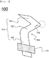
- FIG. 2 is a perspective view showing an electrode lead according to an embodiment of the present invention
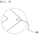
- FIG. 3 is a partial enlarged view of FIG. 2 .
- the electrode lead denoted by reference numeral 100, includes an electrode lead main body 110, which includes a first surface 101, a first bent portion 104, a second surface 102, a second bent portion 105, and a third surface 103.
- the first surface 101 is located at one end of the electrode lead main body 110 based on the first bent portion 104
- the second surface 102 is located at the middle portion of the electrode lead main body 110
- the first bent portion 104 is located between the first surface 101 and the second surface 102.
- the third surface 103 is located at the other end of the electrode lead main body 110, the second bent portion 105 is located between the third surface 103 and the second surface 102, and the second bent portion 105 is bent such that the second surface 102 and the third surface 103 are connected perpendicularly to each other.
- An insulating film 130 is shown as being added to the third surface 103; however, an electrode lead 100 having no insulating film 130 is also included in the present invention.
- FIG. 3 which is an enlarged view of FIG. 2 , shows the state of the electrode lead before the electrode lead is completely bent (a left-side electrode lead enlarged view) and the state of the electrode lead after the electrode lead is completely bent (a right-side electrode lead enlarged view).
- a notch 106 is formed in the first bent portion 104 in the inward direction in which bending is performed.
- a bending process may be easily performed such that the first surface 101 and the second surface 102 are located at the upper surface and the lower surface of an electrode tab.
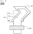
- FIG. 4 is a perspective view showing an electrode lead according to another embodiment of the present invention.
- the electrode lead denoted by reference numeral 200, includes an electrode lead main body 210 and a plastic member 220 disposed so as to surround the outer edge of a portion of the electrode lead main body 210.
- the electrode lead 200 has a structure corresponding to the structure of the electrode lead 100 of FIG. 2 .
- the electrode lead main body 210 includes a first surface 201, a second surface 202, and a third surface 203.
- An insulating film 230 is attached to the third surface 203, and the plastic member 220 is added so as to surround the outer edge of a portion of the third surface 203, the outer edge of the first surface 201, and the outer edge of the second surface 202.
- the plastic member 220 is configured to have a structure that wraps burrs that may be formed at the outer edges of the first surface 201 to the third surface 203, and is capable of preventing a battery case from being damaged by the electrode lead.
- FIG. 5 is a side view schematically showing the state in which the electrode lead of FIG. 4 is coupled to an electrode assembly
- FIG. 6 is a side sectional view schematically showing the state in which the electrode assembly of FIG. 5 is received in a battery case.
- the electrode assembly is a stacked type electrode assembly, in which positive electrodes 331 and negative electrodes 332 are stacked in the state in which separators (not shown) are interposed respectively therebetween.
- Negative electrode tabs 333 protruding from one-side ends of the negative electrodes 332 are coupled to each other at the protruding ends thereof in order to form a bundle of electrode tabs.
- the electrode lead is bent 180 degrees such that a first surface 301 and a second surface 302 face each other in the state in which the bundle of electrode tabs 333 is located therebetween.
- the first surface 301 of the electrode lead main body is located at the upper surface of the bundle of electrode tabs 333, and the second surface 302 of the electrode lead main body is located at the lower surface of the bundle of electrode tabs 333.
- the thickness h1 of the electrode lead main body is shown as being greater than the thickness h2 of the plastic member. Alternatively, however, the thickness of the electrode lead main body may be equal to the thickness of the plastic member.
Landscapes
- Chemical & Material Sciences (AREA)
- Chemical Kinetics & Catalysis (AREA)
- Electrochemistry (AREA)
- General Chemical & Material Sciences (AREA)
- Engineering & Computer Science (AREA)
- Manufacturing & Machinery (AREA)
- Mechanical Engineering (AREA)
- Connection Of Batteries Or Terminals (AREA)
- Secondary Cells (AREA)
- Sealing Battery Cases Or Jackets (AREA)
Abstract
Description
- This application claims the benefit of priority to Korean Patent Application No.
2018-0002887 filed on January 9, 2018 - The present invention relates to an electrode assembly including a plastic member applied to an electrode tabs-lead coupling portion, and more particularly to an electrode assembly configured to have a structure in which a plurality of electrode tabs is coupled to each other by welding, an electrode lead is coupled to the electrode tabs while wrapping the electrode tabs, the electrode lead includes an electrode lead main body, constituted by a first surface configured to be coupled to the upper surface of the electrode tabs, a second surface bent at a first bent portion in the state of being connected to the first surface so as to be coupled to the lower surface of the electrode tabs, and a third surface bent at a second bent portion in the state of being connected to the second surface so as to be withdrawn outside a battery case, and the electrode tabs are coupled to the electrode lead by clinching.
- Secondary batteries, which are capable of being charged and discharged, have attracted considerable attention as power sources for devices requiring high output and large capacity, including an electric vehicle (EV), a hybrid electric vehicle (HEV), and a plug-in hybrid electric vehicle (Plug-In HEV), which have been developed to solve problems, such as air pollution, caused by existing gasoline and diesel vehicles using fossil fuels.
- Secondary batteries may be classified based on the structure of an electrode assembly including a positive electrode, a negative electrode, and a separator interposed between the positive electrode and the negative electrode. Typically, the electrode assembly may be a jelly-roll type (wound type) electrode assembly, which is configured to have a structure in which a long sheet type positive electrode and a long sheet type negative electrode are wound in the state in which a separator is interposed between the positive electrode and the negative electrode, a stacked type electrode assembly, which is configured to have a structure in which a plurality of positive electrodes, cut so as to have a predetermined size, and a plurality of negative electrodes, cut so as to have a predetermined size, are sequentially stacked in the state in which separators are interposed respectively between the positive electrodes and the negative electrodes, or a stacked/folded type electrode assembly, which is configured to have a structure in which unit cells, such as bi-cells or full cells, each of which is configured to have a structure in which predetermined numbers of positive electrodes and negative electrodes are stacked in the state in which separators are disposed respectively between the positive electrodes and the negative electrodes, are wound.
-
FIG. 1 is an exploded perspective view schematically showing the general structure of a conventional typical pouch-shaped secondary battery. - Referring to
FIG. 1 , the pouch-shaped secondary battery, denoted byreference numeral 10, includes anelectrode assembly 30,electrode tabs electrode assembly 30, electrode leads 60 and 70 connected respectively to theelectrode tabs battery case 20 configured to receive theelectrode assembly 30. - The
electrode assembly 30 is a power-generating element including positive electrodes and negative electrodes sequentially stacked in the state in which separators are disposed respectively between the positive electrodes and the negative electrodes. The electrode assembly is configured to have a stacked type structure or a stacked/folded type structure. Theelectrode tabs electrode assembly 30. The electrode leads 60 and 70 are electrically connected to theelectrode tabs electrode assembly 30, respectively, by welding. In addition,insulating films 80, configured to improve sealability between thebattery case 20 and the electrode leads 60 and 70 and, at the same time, to achieve electrical insulation between thebattery case 20 and the electrode leads 60 and 70, are attached to portions of the upper and lower surfaces of the electrode leads 60 and 70. - Each of the
electrode tabs electrode tabs electrode assembly 30, are connected to the electrode leads 60 and 70, for example, in the form of welded portions at which theelectrode tabs - In the case in which the electrode tabs and the electrode leads are made of different materials, ultrasonic welding may be used in order to couple the electrode tabs to the electrode leads. In the case in which the magnitude of ultrasonic energy is high, some of the electrode tabs may be cut due to over-welding. In the case in which low ultrasonic energy is used in order to prevent over-welding, the electrode tabs may become separated from the electrode leads at the welded portion therebetween due to under-welding at the time of coupling the electrode tabs to the electrode leads.
- In addition, the surface of the ultrasonic-welded portion may extend or protrude, i.e. burrs may be formed, whereby the inner surface of the battery case may be damaged. In order to prevent this, a tape is attached to the surface of the battery case that is opposite the ultrasonic-welded portion.
- In connection therewith, Patent Document 1 discloses a battery having a structure in which a lead terminal having an S-shaped bent portion is coupled to one surface of a terminal portion of each of a positive electrode and a negative electrode. Since the lead terminal is coupled to one surface of electrode tabs by welding, however, it is not possible to solve the above problem.
- Patent Document 2 and Patent Document 3 each disclose a pouch-shaped lithium secondary battery having a structure in which an insulative resin is applied to a connection portion between an electrode lead and electrode tabs in order to wrap the connection portion. Since the electrode tabs are coupled to the electrode lead only at one surface of the electrode tabs and one surface of the electrode lead that face each other, however, some of the electrode tabs, the thickness of each of which is relatively small, may be damaged during the coupling process, or the electrode tabs may be separated from the electrode lead due to the weak force of coupling therebetween.
- Therefore, there is urgent necessity for an electrode assembly configured to have a structure that is capable of stably securing coupling between electrode tabs and an electrode lead and preventing the surface of a connection portion between the electrode tabs and the electrode lead from becoming rough, thereby preventing damage to a battery case.
-
- (Patent Document 1) Japanese Patent Application Publication No.
2000-215877 - (Patent Document 2) Korean Patent Application Publication No.
2008-0090753 - (Patent Document 3) Korean Patent Application Publication No.
2016-0119509 - The present invention has been made in view of the above problems, and it is an object of the present invention to provide an electrode assembly configured to have a structure in which a plurality of electrode tabs is coupled to an electrode lead, configured to have a structure that wraps the electrode tabs, by clinching and in which the electrode lead comprises an electrode lead main body, constituted by a first surface configured to be coupled to the upper surface of the electrode tabs, a second surface bent at a first bent portion in the state of being connected to the first surface so as to be coupled to the lower surface of the electrode tabs, and a third surface bent at a second bent portion in the state of being connected to the second surface so as to be withdrawn outside a battery case.
- In accordance with an aspect of the present invention, the above and other objects can be accomplished by the provision of
an electrode assembly configured to have a structure in which
a plurality of electrodes, from each of which an electrode tab protrudes, is stacked, wherein the electrodes are coupled to each other by welding the electrode tabs to each other,
the electrode tabs are coupled to an electrode lead configured to have a structure that wraps the electrode tabs,
the electrode lead comprises
an electrode lead main body, constituted by a first surface configured to be coupled to an upper surface of the electrode tabs, a second surface bent at a first bent portion in a state of being connected to the first surface so as to be coupled to a lower surface of the electrode tabs, and a third surface bent at a second bent portion in a state of being connected to the second surface and configured to be withdrawn outside a battery case, and
the electrode tabs are coupled to the electrode lead by clinching. - In general, electrode tabs protrude from one side or opposite sides of an electrode assembly having a structure in which flat-type electrodes are stacked. Electrode tabs of electrodes having the same polarity are coupled to each other, and coupling is performed by welding, such as ultrasonic welding.
- While the ultrasonic welding is performed in order to couple the electrode tabs to each other, as described above, the outer surface of the electrode tabs may extend or protrude, i.e. burrs may be formed. In the case in which the welded portion of the electrode tabs comes into contact with the battery case, therefore, the battery case may be damaged.
- In the present invention, the electrode lead is configured to have a structure that wraps the electrode tabs, and the electrode lead is coupled to the upper surface and the lower surface of the electrode tabs, whereby it is possible to prevent the rough surface of the welded portion of the electrode tabs from coming into contact with the battery case.
- In addition, conventionally, there is a problem in which the electrode tabs, which are relatively thin, are cut during the coupling process using welding. However, the electrode assembly according to the present invention includes an electrode lead having a structure that surrounds opposite surfaces of the electrode tabs, and the electrode tabs are protected by the electrode lead, whereby it is possible to solve the problem in which the electrode tabs are cut.
- In addition, the electrode tabs are coupled to the electrode lead by clinching. Compared with coupling using welding, welding strength increases, and a problem in which the electrode tabs are damaged due to over-welding or in which adhesion strength decreases due to under-welding is prevented, whereby welding reliability is improved.
- In the electrode assembly, in which the electrode tabs are coupled to the electrode lead, which wraps the upper surface and the lower surface of the electrode tabs, as described above, the electrodes may be either or both of positive electrodes and negative electrodes. It is preferable for both the positive electrodes and the negative electrodes to have the above structure in consideration of improvement in the safety of a battery.
- The battery case may be a pouch-shaped battery case including a structure in which a concave portion configured to receive the electrode assembly is disposed in at least one of an upper case or a lower case.
- The battery case is manufactured so as to have an electrode assembly reception portion having a shape corresponding to the size and thickness of the electrode assembly, which is received in the electrode assembly reception portion. An electrode assembly for high-capacity batteries may have an increased thickness. In this case, the depth of the electrode assembly reception portion formed in the battery case may also be increased. However, there is a limitation on the extent to which the depth of the electrode assembly reception portion can be increased due to the durability and formability of a laminate sheet for the battery case. Consequently, the battery case is manufactured in consideration of the capacity or thickness of the electrode assembly that is received in the battery case and the thickness of the laminate sheet.
- In the electrode assembly according to the present invention, the electrode tabs may be coupled to the electrode lead, and the third surface of the electrode lead main body may be withdrawn outside the battery case through a sealed portion of the battery case. Consequently, the position of the electrode tabs coupling portion may be changed depending on the position at which the concave portion, configured to receive the electrode assembly, is formed.
- That is, the concave portion configured to receive the electrode assembly may be disposed in the upper case or in the lower case, or the concave portion configured to receive the electrode assembly may be disposed in each of the upper case and the lower case. A coupling portion of the electrode tabs may be disposed at the middle portion of the electrode assembly in a stacking direction of the electrode assembly, or may be disposed at one side of the electrode assembly in the stacking direction of the electrode assembly.
- For example, in the case in which the concave portion is disposed in the upper case, the electrode tabs are coupled to each other at the lower side of the electrode assembly, and the electrode tabs are coupled to the electrode lead. In the case in which the concave portion is disposed in the lower case, the electrode tabs are coupled to each other at the upper side of the electrode assembly, and the electrode tabs are coupled to the electrode lead.
- Also, in the case in which the concave portion is formed in each of the upper case and the lower case, the electrode tabs coupling portion is disposed at the middle portion of the electrode assembly in the stacking direction of the electrode assembly.
- In a concrete example, a plastic member may be added so as to surround the outer edges of the second surface and the third surface of the electrode lead main body. Since the plastic member is added, it is possible to wrap burrs formed on the surface of the electrode tabs or burrs formed at the outer edge of the electrode lean main body at the time of ultrasonic welding for coupling between the electrode tabs, whereby it is possible to prevent damage to the battery case.
- A thickness of the plastic member may be equal to a thickness of the electrode lead main body, or may be smaller than the thickness of the electrode lead main body. In the case in which the thickness of the plastic member is larger than the thickness of the electrode lead main body, the coupling between the electrode tabs and the electrode lead through clinching may be adversely affected, which is undesirable.
- The first bent portion is located between the first surface and the second surface of the electrode lead main body, and the electrode lead is bent 180 degrees at the first bent portion such that the first surface and the second surface face each other in the state in which the electrode tabs are located therebetween. Consequently, a notch may be formed in the first bent portion such that the electrode lead is easily bent to wrap the electrode tabs. Specifically, in the case in which the notch is formed inside in the direction in which bending is performed, it is possible to prevent an increase in the thickness of the first bent portion while the first surface and the second surface face each other as the result of bending, thereby capable of easy bending.
- The second bent portion is bent such that the second surface and the third surface are connected perpendicularly to each other. As will be described below, the bent state of the second bent portion is maintained such that the second surface and the third surface are located so as to be perpendicular to each other even when the electrode tabs are bent, and thus the third surface of the electrode lead main body is deformed so as to be withdrawn outside the battery case.
- In a concrete example, an insulating film may be further added to the third surface. The insulating film is attached to the portion of the electrode lead that extends through the sealed portion of the battery case in order to prevent the sealing force of the battery case from being lowered.
- Meanwhile, in order to minimize the formation of dead space in the battery case by reducing the overall size of the electrode assembly coupled to the electrode lead, the electrode assembly may be received in the concave portion configured to receive the electrode assembly, and then the electrode tabs coupled to the electrode lead may be bent so as to be parallel to the stacking direction of the electrode assembly.
- In accordance with another aspect of the present invention, there is provided a secondary battery configured to have a structure in which the electrode assembly is received in a pouch-shaped battery case and in which the third surface of the electrode lead main body is withdrawn outside the battery case through the sealed portion of the battery case.
- In accordance with another aspect of the present invention, there is provided a method of manufacturing the electrode assembly, the method including:
- (a) preparing an electrode assembly configured to have a structure in which a positive electrode and a negative electrode are stacked in the state in which a separator is interposed between the positive electrode and the negative electrode,
- (b) preliminarily coupling electrode tabs of the electrode assembly to each other,
- (c) positioning an electrode lead to surround the electrode tabs, and
- (d) coupling the electrode tabs to the electrode lead by clinching.
- That is, in the method of manufacturing the electrode assembly according to the present invention, first, electrode tabs of electrodes having the same polarity are preliminarily coupled to each other, and then an electrode lead configured to wrap the outer surface of the coupled electrode tabs is coupled to the electrode tabs by clinching. Consequently, it is possible not only to increase the force of coupling between the electrode tabs and the electrode lead but also to prevent damage to the electrode tabs at the time of coupling using a welding method or to prevent the battery case from being damaged by the welded surface.
- At step (b), the electrode tabs may be coupled to each other by welding, specifically ultrasonic welding. The method may further include bending the electrode tabs so as to be parallel to the stacking direction of the electrode assembly after step (d).
- In accordance with a further aspect of the present invention, there are provided a battery pack including the battery cell and a device including the battery pack. The battery pack and the device are well known in the art to which the present invention pertains, and thus a detailed description thereof will be omitted.
- For example, the device may be a laptop computer, a netbook computer, a tablet PC, a mobile phone, an MP3 player, a wearable electronic device, a power tool, an electric vehicle (EV), a hybrid electric vehicle (HEV), a plug-in hybrid electric vehicle (PHEV), an electric bicycle (E-bike), an electric scooter (E-scooter), an electric golf cart, or an energy storage system. However, the present invention is not limited thereto.
-
-
FIG. 1 is a perspective view showing the general structure of a typical pouch-shaped lithium secondary battery including a stacked type electrode assembly. -
FIG. 2 is a perspective view showing an electrode lead according to an embodiment of the present invention. -
FIG. 3 is a partial enlarged view ofFIG. 2 . -
FIG. 4 is a perspective view showing an electrode lead according to another embodiment of the present invention. -
FIG. 5 is a side view showing the state in which the electrode lead ofFIG. 4 is coupled to an electrode assembly. -
FIG. 6 is a side sectional view showing the state in which the electrode assembly ofFIG. 5 is received in a battery case. - Now, preferred embodiments of the present invention will be described in detail with reference to the accompanying drawings such that the preferred embodiments of the present invention can be easily implemented by a person having ordinary skill in the art to which the present invention pertains. In describing the principle of operation of the preferred embodiments of the present invention in detail, however, a detailed description of known functions and configurations incorporated herein will be omitted when the same may obscure the subject matter of the present invention.
- Wherever possible, the same reference numbers will be used throughout the drawings to refer to parts that perform similar functions or operations. Meanwhile, in the case in which one part is said to be 'connected' to another part in the following description of the present invention, not only may the one part be directly connected to the another part, but also, the one part may be indirectly connected to the another part via a further part. In addition, that a certain element is 'included' does not mean that other elements are excluded, but means that such elements may be further included unless mentioned otherwise.
- Reference will now be made in detail to the preferred embodiments of the present invention, examples of which are illustrated in the accompanying drawings.
FIG. 2 is a perspective view showing an electrode lead according to an embodiment of the present invention, andFIG. 3 is a partial enlarged view ofFIG. 2 . - Referring to
FIGS. 2 and3 , the electrode lead, denoted byreference numeral 100, includes an electrode leadmain body 110, which includes afirst surface 101, a firstbent portion 104, asecond surface 102, a secondbent portion 105, and athird surface 103. Thefirst surface 101 is located at one end of the electrode leadmain body 110 based on the firstbent portion 104, thesecond surface 102 is located at the middle portion of the electrode leadmain body 110, and the firstbent portion 104 is located between thefirst surface 101 and thesecond surface 102. Thethird surface 103 is located at the other end of the electrode leadmain body 110, the secondbent portion 105 is located between thethird surface 103 and thesecond surface 102, and the secondbent portion 105 is bent such that thesecond surface 102 and thethird surface 103 are connected perpendicularly to each other. - An insulating
film 130 is shown as being added to thethird surface 103; however, anelectrode lead 100 having no insulatingfilm 130 is also included in the present invention. -
FIG. 3 , which is an enlarged view ofFIG. 2 , shows the state of the electrode lead before the electrode lead is completely bent (a left-side electrode lead enlarged view) and the state of the electrode lead after the electrode lead is completely bent (a right-side electrode lead enlarged view). Anotch 106 is formed in the firstbent portion 104 in the inward direction in which bending is performed. A bending process may be easily performed such that thefirst surface 101 and thesecond surface 102 are located at the upper surface and the lower surface of an electrode tab. -
FIG. 4 is a perspective view showing an electrode lead according to another embodiment of the present invention. - Referring to
FIG. 4 , the electrode lead, denoted by reference numeral 200, includes an electrode leadmain body 210 and aplastic member 220 disposed so as to surround the outer edge of a portion of the electrode leadmain body 210. - The electrode lead 200 has a structure corresponding to the structure of the
electrode lead 100 ofFIG. 2 . The electrode leadmain body 210 includes afirst surface 201, asecond surface 202, and athird surface 203. An insulatingfilm 230 is attached to thethird surface 203, and theplastic member 220 is added so as to surround the outer edge of a portion of thethird surface 203, the outer edge of thefirst surface 201, and the outer edge of thesecond surface 202. - The
plastic member 220 is configured to have a structure that wraps burrs that may be formed at the outer edges of thefirst surface 201 to thethird surface 203, and is capable of preventing a battery case from being damaged by the electrode lead. -
FIG. 5 is a side view schematically showing the state in which the electrode lead ofFIG. 4 is coupled to an electrode assembly, andFIG. 6 is a side sectional view schematically showing the state in which the electrode assembly ofFIG. 5 is received in a battery case. - Referring to
FIGS. 5 and6 , the electrode assembly, denoted byreference numeral 330, is a stacked type electrode assembly, in whichpositive electrodes 331 andnegative electrodes 332 are stacked in the state in which separators (not shown) are interposed respectively therebetween.Negative electrode tabs 333 protruding from one-side ends of thenegative electrodes 332 are coupled to each other at the protruding ends thereof in order to form a bundle of electrode tabs. As shown inFIG. 6 , the electrode lead is bent 180 degrees such that afirst surface 301 and asecond surface 302 face each other in the state in which the bundle ofelectrode tabs 333 is located therebetween. Thefirst surface 301 of the electrode lead main body is located at the upper surface of the bundle ofelectrode tabs 333, and thesecond surface 302 of the electrode lead main body is located at the lower surface of the bundle ofelectrode tabs 333. - The thickness h1 of the electrode lead main body is shown as being greater than the thickness h2 of the plastic member. Alternatively, however, the thickness of the electrode lead main body may be equal to the thickness of the plastic member.
- In the state in which a clinching
punch 351 is located so as to face thefirst surface 301 of the electrode lead main body and in which adie 352 is located so as to face the electrode tabs and thesecond surface 302 of the electrode lead main body, the clinchingpunch 341 is pushed downwards to complete coupling between the electrode tabs and the electrode lead. - The
electrode assembly 330 is configured such that the electrode tabs coupling portion is disposed at the middle portion of theelectrode assembly 330 in the stacking direction of theelectrode assembly 330. Theelectrode assembly 330 is received in the battery case ofFIG. 6 , i.e. a battery case having a structure in which concave portions configured to receive the electrode assembly are disposed both in anupper case 341 and a lower case 243. - Of course, the
electrode tabs 333 may be formed at the upper part or the lower part of theelectrode assembly 330 in the stacking direction of theelectrode assembly 330 in consideration of the thickness of theelectrode assembly 330 and the positions of the concave portions disposed in the battery case. - The
electrode tabs 333 are received in the battery case in the state in which the portion of theelectrode tabs 333 that is coupled to the electrode lead is bent so as to be parallel to the stacking direction of theelectrode assembly 330. In the case in which theelectrode tabs 333 are received in the battery case in the state in which theelectrode tabs 333 are not bent, the size of the dead space in the battery case increases, which is undesirable. - Those skilled in the art to which the present invention pertains will appreciate that various applications and modifications are possible based on the above description without departing from the scope of the present invention.
-
- 10:
- Pouch-shaped secondary battery
- 20:
- Battery case
- 30:
- Electrode assembly
- 40, 50:
- Electrode tabs
- 60, 70:
- Electrode leads
- 80:
- Insulating films
- 100, 200:
- Electrode leads
- 101, 201, 301:
- First surfaces
- 102, 202, 302:
- Second surfaces
- 103, 203, 303:
- Third surfaces
- 104:
- First bent portion
- 105:
- Second bent portion
- 106:
- Notch
- 110, 210:
- Electrode lead main bodies
- 130, 230:
- Insulating films
- 220, 320:
- Plastic members
- 330:
- Electrode assembly
- 331:
- Positive electrodes
- 332:
- Negative electrodes
- 333:
- Negative electrode tabs
- 341:
- Upper case
- 342:
- Lower case
- 351:
- Clinching punch
- 352:
- Die
- h1:
- Thickness of electrode lead main body
- h2:
- Thickness of plastic member
- As is apparent from the above description, an electrode assembly according to the present invention is configured to have a structure in which a plurality of electrode tabs is stacked, and in which an electrode lead, configured to have a structure that wraps the outer surface of the electrode tabs, is coupled to the electrode tabs by clinching. Since the electrode lead is configured to have a structure that wraps both the upper surface and the lower surface of the electrode tabs, it is possible to prevent the electrode tabs from being damaged during the coupling process.
- In addition, since the electrode lead is configured to have a structure that covers the outer surface of the electrode tabs, as described above, it is possible to prevent the inner surface of a battery case from being damaged by burrs formed at the outer surface of the electrode tabs during the process of coupling the electrode tabs.
Claims (14)
- An electrode assembly configured to have a structure in which a plurality of electrodes, from each of which an electrode tab protrudes, is stacked, wherein
the electrodes are coupled to each other by welding the electrode tabs to each other,
the electrode tabs are coupled to an electrode lead configured to have a structure that wraps the electrode tabs,
the electrode lead comprises an electrode lead main body, the electrode lead main body including a first surface configured to be coupled to an upper surface of the electrode tabs, a second surface bent at a first bent portion in a state of being connected to the first surface so as to be coupled to a lower surface of the electrode tabs, and a third surface bent at a second bent portion in a state of being connected to the second surface and configured to be withdrawn outside a battery case, and
the electrode tabs are coupled to the electrode lead by clinching. - The electrode assembly according to claim 1, wherein each of the electrodes is a positive electrode and/or a negative electrode.
- The electrode assembly according to claim 1, wherein the battery case is a pouch-shaped battery case including a structure in which a concave portion configured to receive the electrode assembly is disposed in at least one of an upper case or a lower case.
- The electrode assembly according to claim 1, wherein a coupling portion of the electrode tabs is disposed at a middle portion of the electrode assembly in a stacking direction of the electrode assembly, or is disposed at one side of the electrode assembly in the stacking direction of the electrode assembly.
- The electrode assembly according to claim 1, wherein a plastic member is added so as to surround outer edges of the second surface and the third surface of the electrode lead main body.
- The electrode assembly according to claim 5, wherein a thickness of the plastic member is equal to a thickness of the electrode lead main body.
- The electrode assembly according to claim 1, wherein a notch is formed in the first bent portion.
- The electrode assembly according to claim 1, wherein the second bent portion is bent such that the second surface and the third surface are connected perpendicularly to each other.
- The electrode assembly according to claim 1, wherein an insulating film is further added to the third surface.
- The electrode assembly according to claim 1, wherein the electrode tabs coupled to the electrode lead are bent so as to be parallel to a stacking direction of the electrode assembly.
- A secondary battery configured to have a structure in which the electrode assembly according to any one of claims 1 to 10 is received in a pouch-shaped battery case and in which the third surface of the electrode lead main body is withdrawn outside the battery case through a sealed portion of the battery case.
- A method of manufacturing the electrode assembly according to any one of claims 1 to 10, the method comprising:(a) preparing an electrode assembly configured to have a structure in which a positive electrode and a negative electrode are stacked in a state in which a separator is interposed between the positive electrode and the negative electrode;(b) preliminarily coupling electrode tabs of the electrode assembly to each other;(c) positioning an electrode lead to surround the electrode tabs; and(d) coupling the electrode tabs to the electrode lead by clinching.
- The method according to claim 12, wherein, at step (b), the electrode tabs are coupled to each other by ultrasonic welding.
- The method according to claim 12, further comprising bending the electrode tabs so as to be parallel to a stacking direction of the electrode assembly after step (d).
Applications Claiming Priority (2)
| Application Number | Priority Date | Filing Date | Title |
|---|---|---|---|
| KR1020180002887A KR20190084765A (en) | 2018-01-09 | 2018-01-09 | Electrode Assembly Comprising Plastic Member Applied on Electrode Tab-lead Coupling Portion and Secondary Battery Comprising the Same |
| PCT/KR2018/016607 WO2019139282A1 (en) | 2018-01-09 | 2018-12-24 | Electrode assembly comprising plastic member applied to electrode tab-lead joint part and secondary battery containing same |
Publications (2)
| Publication Number | Publication Date |
|---|---|
| EP3664191A1 true EP3664191A1 (en) | 2020-06-10 |
| EP3664191A4 EP3664191A4 (en) | 2020-11-11 |
Family
ID=67218670
Family Applications (1)
| Application Number | Title | Priority Date | Filing Date |
|---|---|---|---|
| EP18899172.3A Pending EP3664191A4 (en) | 2018-01-09 | 2018-12-24 | ELECTRODE ARRANGEMENT WITH A PLASTIC ELEMENT APPLIED TO A CONNECTING PART OF AN ELECTRODE TUBE SUPPORT, AND SECONDARY BATTERY THEREOF |
Country Status (6)
| Country | Link |
|---|---|
| US (1) | US12463275B2 (en) |
| EP (1) | EP3664191A4 (en) |
| JP (1) | JP7134543B2 (en) |
| KR (1) | KR20190084765A (en) |
| CN (1) | CN110892555B (en) |
| WO (1) | WO2019139282A1 (en) |
Cited By (1)
| Publication number | Priority date | Publication date | Assignee | Title |
|---|---|---|---|---|
| CN112657870A (en) * | 2020-12-21 | 2021-04-16 | 东莞市名动智能科技有限公司 | Automatic detection device and detection line for packaging process of lithium battery PACK |
Families Citing this family (10)
| Publication number | Priority date | Publication date | Assignee | Title |
|---|---|---|---|---|
| KR102751962B1 (en) * | 2020-01-15 | 2025-01-10 | 주식회사 엘지에너지솔루션 | The Apparatus And The Method For Folding Electrode Tab |
| KR102951291B1 (en) * | 2020-07-22 | 2026-04-09 | 주식회사 엘지에너지솔루션 | Battery module having a simple connection structure between cell lead and voltage sensing member and battery pack including the same |
| KR102769119B1 (en) * | 2022-01-14 | 2025-02-18 | 삼성에스디아이 주식회사 | Secondary Battery |
| EP4790826A2 (en) * | 2022-03-11 | 2026-08-12 | LG Energy Solution, Ltd. | Battery cell, and battery module, battery pack and vehicle including the same |
| CN220627729U (en) | 2022-06-27 | 2024-03-19 | 米沃奇电动工具公司 | Fuses and devices including conductive paths for the passage of electric current |
| US20260045647A1 (en) * | 2022-12-20 | 2026-02-12 | Lg Energy Solution, Ltd. | Battery Cell and Battery Module Including the Same |
| KR20250026570A (en) * | 2023-08-17 | 2025-02-25 | 주식회사 엘지에너지솔루션 | Electrode assembly, secondary battery including the electrode assembly, and method for manufacturing the electrode assembly |
| DE102023122544A1 (en) * | 2023-08-23 | 2025-02-27 | Bayerische Motoren Werke Aktiengesellschaft | Battery module and method for producing a battery module |
| CN118872144A (en) * | 2024-03-30 | 2024-10-29 | 宁德新能源科技有限公司 | Secondary batteries and electronic devices |
| KR20260089033A (en) * | 2024-12-06 | 2026-06-15 | 주식회사 엘지에너지솔루션 | Electrode lead assembly and secondary battery |
Family Cites Families (45)
| Publication number | Priority date | Publication date | Assignee | Title |
|---|---|---|---|---|
| JPS55176084U (en) | 1979-06-04 | 1980-12-17 | ||
| JPS5798678U (en) * | 1980-12-10 | 1982-06-17 | ||
| JP3418551B2 (en) | 1998-06-12 | 2003-06-23 | 日本碍子株式会社 | Lithium secondary battery |
| JP2000215877A (en) | 1999-01-20 | 2000-08-04 | Matsushita Electric Ind Co Ltd | Flat battery |
| DE20221990U1 (en) | 2002-06-06 | 2010-06-10 | Varta Microbattery Gmbh | Galvanic element |
| US20050210660A1 (en) * | 2004-03-24 | 2005-09-29 | Wenman Li | Method of fastening electrodes in a lithium-ion powered battery |
| JP4780598B2 (en) | 2004-09-29 | 2011-09-28 | 日立マクセルエナジー株式会社 | Sealed prismatic battery |
| KR20060033642A (en) * | 2004-10-15 | 2006-04-19 | 주식회사 에너랜드 | Electrode Tab Treatment Method of Multilayer Lithium Secondary Battery |
| CN102820435A (en) * | 2005-11-08 | 2012-12-12 | 株式会社Lg化学 | Secondary battery with high safety |
| JP4599314B2 (en) * | 2006-02-22 | 2010-12-15 | 株式会社東芝 | Non-aqueous electrolyte battery, battery pack and automobile |
| KR100846071B1 (en) | 2006-07-18 | 2008-07-14 | 주식회사 엘지화학 | Novel electrode assembly consisting of a novel electrode lead-electrode tab coupling and an electrochemical cell comprising the same |
| KR100866533B1 (en) | 2007-04-06 | 2008-11-03 | 에너테크인터내셔널 주식회사 | Pouch Type Lithium Secondary Battery |
| JP5080199B2 (en) * | 2007-10-19 | 2012-11-21 | プライムアースEvエナジー株式会社 | Secondary battery and method for manufacturing secondary battery |
| CN201122624Y (en) * | 2007-11-30 | 2008-09-24 | 比亚迪股份有限公司 | An electrode lead-out structure and a battery comprising the electrode lead-out structure |
| CN201191634Y (en) * | 2008-04-16 | 2009-02-04 | 耀安电池电源科技(深圳)有限公司 | Secondary ultra-thin cell |
| EP2306554B1 (en) * | 2009-10-01 | 2013-09-11 | Samsung SDI Co., Ltd. | Secondary battery and method of fabricating secondary battery |
| KR101101046B1 (en) * | 2009-12-01 | 2011-12-29 | 삼성에스디아이 주식회사 | Electrode assembly and secondary battery having same |
| US8557417B2 (en) | 2009-12-07 | 2013-10-15 | Samsung Sdi Co., Ltd. | Secondary battery |
| US8760840B2 (en) * | 2010-04-14 | 2014-06-24 | Tdk Corporation | Electrochemical device and manufacturing method thereof, circuit board and housing tray |
| KR101136288B1 (en) * | 2010-05-24 | 2012-04-19 | 삼성에스디아이 주식회사 | Battery pack |
| JP5830953B2 (en) * | 2010-11-17 | 2015-12-09 | ソニー株式会社 | Secondary battery, battery unit and battery module |
| KR101765769B1 (en) | 2010-12-29 | 2017-08-07 | 에스케이이노베이션 주식회사 | Battery module and tab ultrasonic wave welding method |
| US8628874B2 (en) * | 2011-01-28 | 2014-01-14 | Samsung Sdi Co., Ltd. | Secondary battery |
| DE102011109203A1 (en) * | 2011-08-02 | 2013-02-07 | Daimler Ag | Single cell for one battery and one battery |
| JP2013182677A (en) * | 2012-02-29 | 2013-09-12 | Kyocera Corp | Laminate type power storage device |
| KR101914564B1 (en) * | 2012-03-02 | 2018-11-02 | 삼성에스디아이 주식회사 | Secondary battery with insulation member |
| KR101501363B1 (en) * | 2012-08-01 | 2015-03-11 | 주식회사 엘지화학 | Electrode assembly and electrochemical cell containing the same |
| KR101539236B1 (en) | 2012-10-18 | 2015-07-24 | 주식회사 엘지화학 | Battery Cell Having Electrode Lead of Improved Resistance Pressure and Stability |
| JP2014212012A (en) * | 2013-04-18 | 2014-11-13 | トヨタ自動車株式会社 | Method of manufacturing secondary battery and secondary battery |
| JP6155896B2 (en) * | 2013-06-21 | 2017-07-05 | 株式会社Gsユアサ | Storage element and method for manufacturing the same |
| KR101666418B1 (en) * | 2013-09-24 | 2016-10-14 | 주식회사 엘지화학 | Pouch-Type Battery Cell Having Film Member for Protecting Electrode Tap-Lead Joint Portion |
| KR102275421B1 (en) * | 2014-11-19 | 2021-07-12 | 삼성에스디아이 주식회사 | MANUFACTURING METHOD FOR SECONDARY BATTERY and SECONDARY BATTERY USING THE SAME |
| CN104577025B (en) * | 2014-12-29 | 2017-02-08 | 山东精工电子科技有限公司 | Soft packed battery tab welding method |
| KR102324343B1 (en) * | 2015-01-07 | 2021-11-10 | 삼성에스디아이 주식회사 | A secondary battery |
| KR101770334B1 (en) | 2015-04-06 | 2017-08-22 | 주식회사 엘지화학 | Battery Cell containing Protection Circuit Member and Method of Manufacturing the Same |
| KR102446407B1 (en) * | 2015-05-06 | 2022-09-22 | 삼성전자주식회사 | Cell structure for secondary battery and secondary battery comprising same |
| CN107710074B (en) | 2015-06-24 | 2019-07-16 | 互应化学工业株式会社 | Solder resist composition, film, covered printed wiring board, method for producing film, and method for producing covered printed wiring board |
| JP6651772B2 (en) * | 2015-09-30 | 2020-02-19 | 株式会社Gsユアサ | Method of manufacturing power storage element and power storage element |
| KR102510884B1 (en) * | 2015-11-19 | 2023-03-16 | 삼성에스디아이 주식회사 | Secondary battery |
| KR20170095072A (en) * | 2016-02-12 | 2017-08-22 | 주식회사 엘지화학 | Secondary battery and method for manufacturing the secondary battery |
| JP6788821B2 (en) | 2016-05-31 | 2020-11-25 | 株式会社Gsユアサ | Power storage element, power storage device, and manufacturing method of power storage element |
| KR102124640B1 (en) * | 2016-12-21 | 2020-06-18 | 주식회사 엘지화학 | Electrode Assembly Comprising Electrode Lead Coupled to Long Side Portion |
| KR102313058B1 (en) * | 2017-03-23 | 2021-10-18 | 주식회사 엘지에너지솔루션 | Secondary Battery Cell with Less Modification of External Form of Battery Case |
| KR102328993B1 (en) * | 2017-09-07 | 2021-11-22 | 주식회사 엘지에너지솔루션 | Pouch type secondary battery |
| US11201318B2 (en) * | 2017-09-15 | 2021-12-14 | Honda Motor Co., Ltd. | Method for battery tab attachment to a self-standing electrode |
-
2018
- 2018-01-09 KR KR1020180002887A patent/KR20190084765A/en not_active Ceased
- 2018-12-24 WO PCT/KR2018/016607 patent/WO2019139282A1/en not_active Ceased
- 2018-12-24 CN CN201880046012.4A patent/CN110892555B/en active Active
- 2018-12-24 EP EP18899172.3A patent/EP3664191A4/en active Pending
- 2018-12-24 US US16/620,997 patent/US12463275B2/en active Active
- 2018-12-24 JP JP2019559351A patent/JP7134543B2/en active Active
Cited By (1)
| Publication number | Priority date | Publication date | Assignee | Title |
|---|---|---|---|---|
| CN112657870A (en) * | 2020-12-21 | 2021-04-16 | 东莞市名动智能科技有限公司 | Automatic detection device and detection line for packaging process of lithium battery PACK |
Also Published As
| Publication number | Publication date |
|---|---|
| JP7134543B2 (en) | 2022-09-12 |
| JP2020518963A (en) | 2020-06-25 |
| EP3664191A4 (en) | 2020-11-11 |
| US20200203700A1 (en) | 2020-06-25 |
| KR20190084765A (en) | 2019-07-17 |
| US12463275B2 (en) | 2025-11-04 |
| CN110892555B (en) | 2022-12-23 |
| WO2019139282A1 (en) | 2019-07-18 |
| CN110892555A (en) | 2020-03-17 |
Similar Documents
| Publication | Publication Date | Title |
|---|---|---|
| US12463275B2 (en) | Electrode assembly including plastic member applied to electrode tabs-lead coupling portion and secondary battery including the same | |
| US11437683B2 (en) | Battery cell of venting structure using taping | |
| EP3907818B1 (en) | Battery pack having movable busbar assembly and secondary battery including the same | |
| EP2811571B1 (en) | Secondary battery having improved energy density | |
| CN103081161B (en) | Secondary battery pouch with improved stability, pouch-type secondary battery using the same, and medium-to-large-sized battery pack | |
| US8815426B2 (en) | Prismatic sealed secondary cell and method of manufacturing the same | |
| EP2254176B1 (en) | Rechargeable battery | |
| US11316235B2 (en) | Prismatic secondary battery, assembled battery using the same and method of producing the same | |
| EP4336521A1 (en) | Connection wire and battery pack including same | |
| US20130252078A1 (en) | Secondary battery | |
| CN114447536A (en) | Battery and method for manufacturing battery | |
| CN115699443A (en) | Battery cell including electrode tab formed with stress relief | |
| US12381288B2 (en) | Busbar module and method of manufacturing the same | |
| KR102700494B1 (en) | Battery | |
| KR20150072236A (en) | A Pouch Packaging Structure Having Sealed Terrace Area and a Method thereof | |
| KR20230029531A (en) | Battery | |
| CN223713025U (en) | Battery cell, battery device and electricity utilization device | |
| US20240097177A1 (en) | Electrode Assembly and Battery Cell Including the Same | |
| KR20170096743A (en) | Battery Cell Having Sealing Protrusion Between Electrode Terminals | |
| CN116073051A (en) | Battery | |
| KR101890014B1 (en) | Electrode lead and battery module for high capacity comprising the same | |
| US20250087851A1 (en) | Method of manufacturing secondary battery and secondary battery | |
| US20260121263A1 (en) | Cylindrical Battery Cell Including Composite Current Collector | |
| EP4715998A1 (en) | Secondary battery | |
| CN121812677A (en) | Power storage device |
Legal Events
| Date | Code | Title | Description |
|---|---|---|---|
| STAA | Information on the status of an ep patent application or granted ep patent |
Free format text: STATUS: THE INTERNATIONAL PUBLICATION HAS BEEN MADE |
|
| PUAI | Public reference made under article 153(3) epc to a published international application that has entered the european phase |
Free format text: ORIGINAL CODE: 0009012 |
|
| STAA | Information on the status of an ep patent application or granted ep patent |
Free format text: STATUS: REQUEST FOR EXAMINATION WAS MADE |
|
| 17P | Request for examination filed |
Effective date: 20200204 |
|
| AK | Designated contracting states |
Kind code of ref document: A1 Designated state(s): AL AT BE BG CH CY CZ DE DK EE ES FI FR GB GR HR HU IE IS IT LI LT LU LV MC MK MT NL NO PL PT RO RS SE SI SK SM TR |
|
| AX | Request for extension of the european patent |
Extension state: BA ME |
|
| A4 | Supplementary search report drawn up and despatched |
Effective date: 20201014 |
|
| RIC1 | Information provided on ipc code assigned before grant |
Ipc: H01M 2/26 20060101AFI20201008BHEP Ipc: H01M 2/02 20060101ALI20201008BHEP Ipc: H01M 10/04 20060101ALI20201008BHEP Ipc: H01M 10/0585 20100101ALI20201008BHEP Ipc: H01M 2/08 20060101ALI20201008BHEP Ipc: H01M 2/06 20060101ALI20201008BHEP Ipc: B23K 101/38 20060101ALI20201008BHEP Ipc: B23K 20/10 20060101ALI20201008BHEP |
|
| DAV | Request for validation of the european patent (deleted) | ||
| DAX | Request for extension of the european patent (deleted) | ||
| RAP1 | Party data changed (applicant data changed or rights of an application transferred) |
Owner name: LG ENERGY SOLUTION LTD. |
|
| RAP3 | Party data changed (applicant data changed or rights of an application transferred) |
Owner name: LG ENERGY SOLUTION, LTD. |
|
| STAA | Information on the status of an ep patent application or granted ep patent |
Free format text: STATUS: EXAMINATION IS IN PROGRESS |
|
| 17Q | First examination report despatched |
Effective date: 20230508 |