EP3664050A1 - Paper sheet processing system and paper sheet processing method - Google Patents
Paper sheet processing system and paper sheet processing method Download PDFInfo
- Publication number
- EP3664050A1 EP3664050A1 EP18842023.6A EP18842023A EP3664050A1 EP 3664050 A1 EP3664050 A1 EP 3664050A1 EP 18842023 A EP18842023 A EP 18842023A EP 3664050 A1 EP3664050 A1 EP 3664050A1
- Authority
- EP
- European Patent Office
- Prior art keywords
- banknotes
- sheets
- banknote
- loading
- storage unit
- Prior art date
- Legal status (The legal status is an assumption and is not a legal conclusion. Google has not performed a legal analysis and makes no representation as to the accuracy of the status listed.)
- Withdrawn
Links
- 238000003672 processing method Methods 0.000 title 1
- 238000011068 loading method Methods 0.000 claims abstract description 390
- 238000003860 storage Methods 0.000 claims abstract description 348
- 238000000034 method Methods 0.000 claims abstract description 103
- 230000008569 process Effects 0.000 claims abstract description 87
- 230000032258 transport Effects 0.000 description 176
- 238000007726 management method Methods 0.000 description 75
- 238000010586 diagram Methods 0.000 description 18
- 230000015572 biosynthetic process Effects 0.000 description 9
- 238000004891 communication Methods 0.000 description 8
- 238000001514 detection method Methods 0.000 description 7
- 238000012986 modification Methods 0.000 description 4
- 230000004048 modification Effects 0.000 description 4
- 238000012790 confirmation Methods 0.000 description 3
- 230000006870 function Effects 0.000 description 3
- 239000004973 liquid crystal related substance Substances 0.000 description 3
- 230000007246 mechanism Effects 0.000 description 3
- 238000002360 preparation method Methods 0.000 description 3
- 239000004065 semiconductor Substances 0.000 description 3
- 238000013500 data storage Methods 0.000 description 2
- 238000010923 batch production Methods 0.000 description 1
- 230000008859 change Effects 0.000 description 1
- 230000000694 effects Effects 0.000 description 1
- 238000005516 engineering process Methods 0.000 description 1
- 238000004519 manufacturing process Methods 0.000 description 1
- 230000002265 prevention Effects 0.000 description 1
- 238000011144 upstream manufacturing Methods 0.000 description 1
Images


Classifications
-
- G—PHYSICS
- G07—CHECKING-DEVICES
- G07D—HANDLING OF COINS OR VALUABLE PAPERS, e.g. TESTING, SORTING BY DENOMINATIONS, COUNTING, DISPENSING, CHANGING OR DEPOSITING
- G07D11/00—Devices accepting coins; Devices accepting, dispensing, sorting or counting valuable papers
- G07D11/20—Controlling or monitoring the operation of devices; Data handling
- G07D11/30—Tracking or tracing valuable papers or cassettes
-
- B—PERFORMING OPERATIONS; TRANSPORTING
- B65—CONVEYING; PACKING; STORING; HANDLING THIN OR FILAMENTARY MATERIAL
- B65H—HANDLING THIN OR FILAMENTARY MATERIAL, e.g. SHEETS, WEBS, CABLES
- B65H31/00—Pile receivers
- B65H31/30—Arrangements for removing completed piles
- B65H31/3036—Arrangements for removing completed piles by gripping the pile
- B65H31/3045—Arrangements for removing completed piles by gripping the pile on the outermost articles of the pile for clamping the pile
-
- G—PHYSICS
- G07—CHECKING-DEVICES
- G07D—HANDLING OF COINS OR VALUABLE PAPERS, e.g. TESTING, SORTING BY DENOMINATIONS, COUNTING, DISPENSING, CHANGING OR DEPOSITING
- G07D11/00—Devices accepting coins; Devices accepting, dispensing, sorting or counting valuable papers
- G07D11/10—Mechanical details
- G07D11/12—Containers for valuable papers
-
- G—PHYSICS
- G07—CHECKING-DEVICES
- G07D—HANDLING OF COINS OR VALUABLE PAPERS, e.g. TESTING, SORTING BY DENOMINATIONS, COUNTING, DISPENSING, CHANGING OR DEPOSITING
- G07D11/00—Devices accepting coins; Devices accepting, dispensing, sorting or counting valuable papers
- G07D11/10—Mechanical details
- G07D11/16—Handling of valuable papers
-
- G—PHYSICS
- G07—CHECKING-DEVICES
- G07D—HANDLING OF COINS OR VALUABLE PAPERS, e.g. TESTING, SORTING BY DENOMINATIONS, COUNTING, DISPENSING, CHANGING OR DEPOSITING
- G07D11/00—Devices accepting coins; Devices accepting, dispensing, sorting or counting valuable papers
- G07D11/20—Controlling or monitoring the operation of devices; Data handling
- G07D11/32—Record keeping
-
- B—PERFORMING OPERATIONS; TRANSPORTING
- B65—CONVEYING; PACKING; STORING; HANDLING THIN OR FILAMENTARY MATERIAL
- B65H—HANDLING THIN OR FILAMENTARY MATERIAL, e.g. SHEETS, WEBS, CABLES
- B65H2301/00—Handling processes for sheets or webs
- B65H2301/40—Type of handling process
- B65H2301/42—Piling, depiling, handling piles
- B65H2301/422—Handling piles, sets or stacks of articles
- B65H2301/4224—Gripping piles, sets or stacks of articles
- B65H2301/42242—Gripping piles, sets or stacks of articles by acting on the outermost articles of the pile for clamping the pile
-
- B—PERFORMING OPERATIONS; TRANSPORTING
- B65—CONVEYING; PACKING; STORING; HANDLING THIN OR FILAMENTARY MATERIAL
- B65H—HANDLING THIN OR FILAMENTARY MATERIAL, e.g. SHEETS, WEBS, CABLES
- B65H2301/00—Handling processes for sheets or webs
- B65H2301/40—Type of handling process
- B65H2301/42—Piling, depiling, handling piles
- B65H2301/422—Handling piles, sets or stacks of articles
- B65H2301/4225—Handling piles, sets or stacks of articles in or on special supports
- B65H2301/42254—Boxes; Cassettes; Containers
- B65H2301/422542—Boxes; Cassettes; Containers emptying or unloading processes
-
- B—PERFORMING OPERATIONS; TRANSPORTING
- B65—CONVEYING; PACKING; STORING; HANDLING THIN OR FILAMENTARY MATERIAL
- B65H—HANDLING THIN OR FILAMENTARY MATERIAL, e.g. SHEETS, WEBS, CABLES
- B65H2301/00—Handling processes for sheets or webs
- B65H2301/40—Type of handling process
- B65H2301/42—Piling, depiling, handling piles
- B65H2301/422—Handling piles, sets or stacks of articles
- B65H2301/4225—Handling piles, sets or stacks of articles in or on special supports
- B65H2301/42254—Boxes; Cassettes; Containers
- B65H2301/422548—Boxes; Cassettes; Containers filling or loading process
-
- B—PERFORMING OPERATIONS; TRANSPORTING
- B65—CONVEYING; PACKING; STORING; HANDLING THIN OR FILAMENTARY MATERIAL
- B65H—HANDLING THIN OR FILAMENTARY MATERIAL, e.g. SHEETS, WEBS, CABLES
- B65H2701/00—Handled material; Storage means
- B65H2701/10—Handled articles or webs
- B65H2701/19—Specific article or web
- B65H2701/1912—Banknotes, bills and cheques or the like
Definitions
- the present invention relates to a sheet handling system and a sheet handling method that handle sheets.
- Patent Literature 1 discloses a system in which a working robot loads a large number of banknotes into cassettes for carrying banknotes. Using the working robot enhances the efficiency of the work of loading the large number of banknotes into the cassettes.
- Serial numbers are printed on banknotes as identification information for the purpose of forgery prevention, etc. Banknotes can be distinguished from each other based on the serial numbers printed thereon. Reading the serial number of a banknote before storing the banknote in a cassette enables strict management of the banknote stored in the cassette, based on the serial number.
- the order of the serial numbers of a plurality of banknotes is not managed.
- the serial numbers of all banknotes stored in a container such as a cassette may be known, but the serial numbers cannot be specified in the alignment order of the banknotes. For example, when banknotes, which are stored in a container so as to be stacked in the up-down direction, are taken out in order from the uppermost banknote, the serial numbers of the banknotes cannot be specified.
- the present invention is made in view of the problem of the conventional art described above, and an object of the present invention is to provide a sheet handling system and a sheet handling method capable of managing identification information of a plurality of sheets stored in a container, and the order of the identification information of each sheet.
- the present invention is provided with: a first storage unit configured to stack sheets; a second storage unit configured to stack the sheets; a loading apparatus configured to execute a loading process of taking out the sheets stacked in the first storage unit, and loading the taken-out sheets into the second storage unit while maintaining a stacked state of the sheets; and a management apparatus configured to generate second data from first data based on that the loading process has been performed by the loading apparatus, the first data specifying identification information of the respective sheets stacked in the first storage unit in an order in which the sheets are stacked, the second data specifying identification information of the respective sheets stacked in the second storage unit in an order in which the sheets are stacked.
- the management apparatus when the loading process has been executed a plurality of times by the loading apparatus, the management apparatus generates the second data from the first data on the basis of contents of the loading process executed the plurality of times.
- the loading apparatus includes a holding unit configured to hold the sheets stacked in the first storage unit, and move the sheets into the second storage unit.
- the above configuration further includes a sheet handling apparatus configured to recognize sheets to obtain the identification information.
- the sheet handling apparatus includes the first storage unit.
- the loading apparatus takes out the stacked sheets and loads the taken-out sheets into the second storage unit based on that the number of sheets stacked in the first storage unit has reached a predetermined number.
- the first storage unit includes a plurality of first storage spaces for stacking sheets therein.
- the loading apparatus sequentially takes out the stacked sheets in order from the first storage space in which the number of stacked sheets has reached a predetermined number among the plurality of first storage spaces, and loads the taken-out sheets into the second storage unit.
- the loading apparatus takes out sheets from the plurality of first storage spaces in a predetermined order.
- the loading apparatus is configured to perform a first loading process of loading the sheets taken out from the first storage unit into the second storage unit such that top/bottom orientation of the sheets is changed without changing face/back orientation of the sheets.
- the management apparatus When the first loading process has been performed by the loading apparatus, the management apparatus generates the second data from the first data such that an arrangement order of the identification information in the second data matches an arrangement order of the identification information in the first data.
- the loading apparatus is configured to perform a second loading process of changing face/back orientation of the sheets when loading the sheets taken out from the first storage unit into the second storage unit.
- the management apparatus When the second loading process has been performed by the loading apparatus, the management apparatus generates the second data from the first data such that an arrangement order of the identification information in the second data is reversed from an arrangement order of the identification information in the first data.
- the loading apparatus makes face/back orientations of all the sheets loaded into the second storage unit uniform by performing the second loading process.
- the sheets each have a first region and a second region thicker than the first region.
- the loading apparatus loads a predetermined number of sheets into the second storage unit such that the second regions overlap each other, and thereafter, loads a predetermined number of sheets in the second storage unit such that the second regions of the sheets do not overlap the second regions of the already loaded sheets.
- the second storage unit includes a plurality of second storage spaces to be loaded with sheets.
- the plurality of second storage spaces are respectively associated with storage space information.
- the management apparatus associates the storage space information corresponding to a predetermined second storage space among the plurality of second storage spaces, with identification information of sheets stored in the predetermined second storage space.
- the first storage unit includes a plurality of first storage spaces to be stacked with sheets.
- the first data is generated for each of the plurality of first storage spaces.
- the management apparatus generates the second data from the first data on the basis of an order in which the sheets have been taken out from the plurality of first storage spaces.
- the identification information includes at least serial number information of the sheets.
- the present invention is a sheet handling method, including: taking out stacked sheets from a first storage unit; acquiring first data specifying identification information of the respective sheets stacked in the first storage unit in an order in which the sheets are stacked in the first storage unit; performing a loading process of loading the sheets taken out from the first storage unit, into the second storage unit while maintaining a stacked state of the sheets, and generating second data from first data based on that the loading process has been performed, the second data specifying identification information of the respective sheets stacked in the second storage unit in an order in which the sheets are stacked.
- sheets can be taken out from the plurality of storage spaces of the first storage unit and loaded into the second storage unit by the loading apparatus.
- the management apparatus generates second data from first data.
- the first data includes identification information of the sheets taken out from each storage space.
- the second data allows identification information of the sheets loaded into the second storage unit to be specified.
- the second data is generated based on the first data and the loading order of the sheets loaded into the second storage unit. Referring to the second data allows the identification information of the sheets in the second storage unit to be specified in the alignment order of the sheets in the second storage unit.
- sheets to be handled in the sheet handling system and the sheet handling method according to the present invention the kinds thereof are not particularly limited as long as the sheets have identification information with which the sheets can be distinguished from each other.
- Various kinds of sheets such as banknotes having serial numbers printed thereon, and checks and gift coupons having identification numbers printed thereon, may be targets to be handled in the sheet handling system and the sheet handling method.
- a banknote handling system and a banknote handling method that handle banknotes will be described as an example.
- FIG. 1 illustrates the banknote handling.
- FIG. 1A is a schematic diagram showing an example of movement of actual banknotes.
- FIG. 1B is a diagram showing examples of data that are processed in association with movement of the banknotes.
- FIG. 1C is a diagram showing examples of data obtained in a case where the face/back orientation of the banknotes is made uniform while moving the banknotes.
- the banknote handling system includes a loading apparatus 10, a first storage unit 21, a second storage unit 22, and a management apparatus 30.
- the first storage unit 21 includes at least one storage space. In each storage space, a plurality of banknotes are stored in an aligned state. In the present embodiment, the phrase "stored in an aligned state" means that a plurality of banknotes are stored without changing the alignment order thereof.
- FIG. 1A shows a case where the first storage unit 21 has three storage spaces. In the respective storage spaces, a plurality of banknotes 100 (100a to 100c) are stored in an aligned state (stacked state) in which the banknotes are stacked with their faces in parallel with each other.
- Each storage space of the first storage unit 21 has a shape that allows all the banknotes stored therein to be taken out.
- a storage case for banknotes such as a container or a cassette
- an open-type stacking unit of a banknote handling apparatus (sheet handling apparatus) is available as the first storage unit 21.
- the open-type stacking unit is a stacking unit in which the banknote handling apparatus stacks banknotes and which has an opening through which stacked banknotes are taken out from the apparatus.
- the open-type stacking unit of the banknote handling apparatus is simply referred to as "stacking unit".
- the second storage unit 22 includes at least one storage space. In each storage space, a plurality of banknotes are stored in an aligned state. Although the number of the storage spaces of the second storage unit 22 is not particularly limited, FIG. 1A shows a case where the second storage unit 22 has one storage space. Each storage space has a shape that allows a plurality of banknotes to be loaded therein. Specifically, a storage case for banknotes, such as a container or a cassette, is available as the second storage unit 22.
- the loading apparatus 10 takes out the banknotes from each storage space of the first storage unit 21, and loads the taken-out banknotes into each storage space of the second storage unit 22. As shown in FIG. 1A , the loading apparatus 10 takes out all the stored banknotes from each storage space of the first storage unit 21 while keeping the aligned state of the banknotes. Then, the loading apparatus 10 loads all the taken-out banknotes into the second storage unit 22 while keeping the aligned state, and therefore the order of the banknotes is not changed.
- the loading apparatus 10 controls an arm unit 11, which is a joined-arm robot, to hold and move banknotes in a stacked state.
- the arm unit 11 includes a hand assembly (holding member) capable of holding an object.
- the arm unit 11 holds and moves banknotes in a bundle form.
- the loading apparatus 10 controls at least one arm unit 11 to hold and take out banknotes stored in the storage space of the first storage unit 21, and load the banknotes into the storage space of the second storage unit 22.
- the arm unit 11 of the loading apparatus 10 has a camera that takes an image of a target to be handled by the arm unit 11.
- the loading apparatus 10 analyzes the image captured by this camera to recognize the position of each storage space of the first storage unit 21, presence/absence of banknotes in each storage space, the storage state of banknotes, etc.
- the loading apparatus 10 recognizes the position of each storage space of the second storage unit 22, presence/absence of banknotes in each storage space, the storage state of banknotes, etc. Based on these recognition results, the loading apparatus 10 controls the arm unit 11 to execute the banknote taking-out process and the banknote loading process.
- information about the banknotes stored in the respective storage spaces of the first storage unit 21 is stored in a memory device 122 in advance as banknote data 121 (121a to 121c) .
- the first storage unit 21 is a storage case, such as a container or a cassette
- information about banknotes stored in the storage case is stored as the banknote data 121 in a data storage medium
- this data storage medium is used as the memory device 122.
- this external apparatus is used as the memory device 122.
- the first storage unit 21 is a banknote handling apparatus and information about banknotes stacked in stacking units of the sheet handling apparatus is managed as the banknote data 121 in the banknote handling apparatus
- this banknote handling apparatus is used as the memory device 122.
- the banknote data 121 is stored in an external apparatus such as an operation terminal or a server which is connected to the banknote handling apparatus, this external apparatus is used as the memory device 122.
- the banknote data 121 is managed for each of the storage spaces of the first storage unit 21. Specifically, three banknote data 121a to 121c are managed in the memory device 122 as shown in FIG. 1B Three banknote data 121a to 121c correspond to the banknotes 100a to 100c stored in bundle forms in the three storage spaces of the first storage unit 21 as shown in FIG. 1A .
- the banknote data 121a includes: the number of banknotes forming the bundle of banknotes 100a; and the denomination, fitness/unfitness, face/back orientation, top/bottom (portrait-up/portrait-down) orientation, serial number, etc., of each banknote.
- the serial numbers included in the banknote data 121a are managed such that correspondence between the alignment order of the serial numbers and the alignment order of the banknotes forming the bundle of banknotes 100a can be specified.
- the serial numbers of the respective banknotes can be specified with reference to the banknote data 121a.
- the banknote data 121b includes: the number of banknotes forming the bundle of banknotes 100b; and the denomination, fitness/unfitness, face/back orientation, top/bottom orientation, serial number, etc., of each banknote.
- the serial numbers are managed so that correspondence between the alignment order of the serial numbers and the alignment order of the banknotes can be specified.
- the banknote data 121c includes: the number of banknotes forming the bundle of banknotes 100c; and the denomination, fitness/unfitness, face/back orientation, top/bottom orientation, serial number, etc., of each banknote.
- the serial numbers are managed so that correspondence between the alignment order of the serial numbers and the alignment order of the banknotes can be specified.
- the management apparatus 30 is communicably connected to the loading apparatus 10.
- the management apparatus 30 obtains loading data 110 from the loading apparatus 10.
- the loading data 110 includes information regarding movement of the arm unit 11.
- the loading apparatus 10 controls the arm unit 11 to move the banknotes 100a, taken out from the first storage unit 21, to the second storage unit 22, the loading apparatus 10 transmits information indicating this movement as the loading data 110 to the management apparatus 30.
- the loading data 110 includes information indicating the position of a storage space from which the arm unit 11 has taken out the banknotes 100. Based on this information, the management apparatus 30 can specify the banknotes 100, among the banknotes 100a to 100c, which have been taken out.
- the loading data 110 includes information indicating the position of a storage space into which the arm unit 11 has loaded the banknotes 100. Based on this information, the management apparatus 30 can specify a storage space, among the plurality of storage spaces of the second storage unit 22, into which the banknotes 100 taken out from the first storage unit 21 have been loaded.
- the management apparatus 30 obtains, from the memory device 122, banknote data 121 (first data) corresponding to the banknotes 100 taken out from the first storage unit 21 by the loading apparatus 10. Each time the loading apparatus 10 performs taking-out and loading of banknotes 100, the management apparatus 30 obtains the banknote data 121 of the loaded banknotes 100 and generates stored-banknote data 130 (130a, 130b) as shown in FIGS. 1B and 1CFIG. 1C .
- the stored-banknote data (second data) 130 includes: the number of banknotes 200 stored in the second storage unit 22; and the denomination, fitness/unfitness, face/back orientation, top/bottom orientation, serial number, etc., of each banknote.
- the loading apparatus 10 controls the arm unit 11 to load the banknotes in order of banknotes 100a, 100c, and 100b from the first storage unit 21 to the second storage unit 22.
- the management apparatus 30 obtains banknote data 121a to 121c corresponding to the banknotes 100a to 100c from the memory device 122.
- the management apparatus 30 recognizes the loading order of the banknotes 100a to 100c into the second storage unit 22.
- the management apparatus 30 combines the banknote data 121a to 121c according to the loading order, i.e., in order of banknote data 121a, 121c, and 121b, thereby generating stored-banknote data 130a shown in FIG. 1B .
- the banknote data 121 having the serial numbers arranged in the up-down direction as shown in FIG. 1B corresponds to the alignment order of the banknotes 100 stacked in the up-down direction as shown in FIG. 1A .
- the loading apparatus 10 controls the arm unit 11 to stack and load the banknotes 100a, 100c, and 100b in order, from the lower side of the storage space in the second storage unit 22.
- the management apparatus 30 combines the banknote data 121a, 121c, and 121b as shown in FIG. 1B to generate the stored-banknote data 130a.
- the serial number of the lowermost banknote, among the banknotes 200 loaded into the second storage unit 22 so as to be stacked in the up-down direction is the lowermost serial number in the stored-banknote data 130a shown in FIG. 1B .
- the serial number of the uppermost banknote among stacked banknotes 200 is the uppermost serial number in the stored-banknote data 130a.
- the method of managing the serial numbers in the stored-banknote data 130 is not particularly limited as long as the serial numbers of all the banknotes 200 loaded into the second storage unit 22 can be specified in the alignment order of the banknotes 200 loaded into the second storage unit 22.
- numbers indicating the alignment order of the actual banknotes in the second storage unit 22 may be added to the respective serial numbers included in the stored-banknote data 130a to be managed.
- the banknotes are taken out one time from each of the different storage spaces in the above example, it is possible to similarly generate and manage stored-banknote data 130 also in a case where banknotes are taken out a plurality of times from one storage space or a case where banknotes are taken out a plurality of times from each of a plurality of storage spaces.
- the serial numbers of all the banknotes 200 loaded into the second storage unit 22 become able to be specified in the alignment order of the respective banknotes 200 based on the stored-banknote data 130.
- the serial numbers of all the taken-out banknotes can be specified in the order in which the banknotes have been taken out.
- banknotes to be used for a dispensing process in an ATM are prepared by using the first storage unit 21 that is a stacking unit of a banknote handling. These banknotes for the ATM dispensing process, which have been prepared in the stacking unit of the banknote handling apparatus, are loaded into the second storage unit 22 that is an ATM cassette.
- the serial numbers of all the banknotes loaded into the ATM cassette become able to be specified in the alignment order of the banknotes in the ATM cassette, with reference to the stored-banknote data 130.
- the ATM cassette is mounted to the ATM.
- the ATM sequentially feeds out the banknotes stored in the ATM cassette one by one. At this time, the serial numbers of the respective banknotes dispensed from the ATM can be specified based on the stored-banknote data 130.
- the loading apparatus 10 controls the arm unit 11 to move the banknotes 100 from the first storage unit 21 to the second storage unit 22, the face/back orientation of the banknotes 100 can be reversed.
- the banknotes stored in the first storage unit 21 are three banknotes aligned in order of A, B, and C from the upper side.
- the loading apparatus 10 holds all the three banknotes A to C with the arm unit 11, takes out the banknotes from the first storage unit 21, and loads the banknotes into the second storage unit 22.
- the loading apparatus 10 can load the held banknotes A to C into the second storage unit 22 while keeping the alignment order of A, B, and C from the upper side.
- the loading apparatus 10 may control the arm unit 11 to reverse, in the up-down direction, the banknotes A to C held in the bundle form, and load the banknotes into the second storage unit 22 in an alignment order of C, B, and A from the upper side.
- the face/back orientations of all the banknotes 200 to be loaded into the second storage unit 22 can be made uniform.
- the loading apparatus 10 recognizes whether the banknotes 100 taken out from the first storage unit 21 are aligned with their faces directed upward or aligned with their backs directed upward. Then, the loading apparatus 10 reverses only either of the banknotes whose faces directed upward and the banknotes whose backs directed upward to make the face/back orientations of all the banknotes uniform.
- the loading apparatus 10 captures an image of banknotes 100 with a camera and recognizes the face/back orientation based on the captured image. For another example, the loading apparatus 10 recognizes the face/back orientation included in the banknote data 121 in the memory device 122.
- the management apparatus 30 obtains the banknote data 121 corresponding to the taken-out banknotes 100 based on the loading data 110 received from the loading apparatus 10. The management apparatus 30 recognizes the face/back orientation of taken-out banknotes 100 based on the obtained banknote data 121, and notifies the loading apparatus 10 of the recognized face/back orientation.
- the banknotes 100 stored in each storage space of the first storage unit 21 are aligned in uniform face/back orientation, this can be recognized with reference to the banknote data 121 shown in FIG. 1C .
- the banknotes 100a and the banknotes 100c stored in the first storage unit 21 are face-up banknotes that are aligned with their faces directed upward, while the banknotes 100b are face-down banknotes that are aligned with their backs directed upward.
- the loading apparatus 10 When the loading apparatus 10 is set to make face/back orientations of the banknotes 200 to be loaded into the second storage unit 22 uniform, the loading apparatus 10 loads all the banknotes 100 with their faces directed upward, for example. It is assumed that the banknotes 100a to 100c having been stored in the first storage unit 21 are loaded in order of banknotes 100a, 100c, and 100b into the second storage unit 22.
- the banknote data 121a to 121c shown in FIG. 1C correspond to the banknotes 100a to 100c, respectively.
- the loading apparatus 10 recognizes that the banknotes 100a and 100c taken out from the first storage unit 21 are face-up banknotes, and loads the banknotes into the second storage unit 22 as they are without reversing the face/back orientation of the banknotes 100a and 100c. Meanwhile, the loading apparatus 10 recognizes that the banknotes 100b taken out from the first storage unit 21 are face-down banknotes, reverses the face/back orientation of the taken-out banknotes 100b held in the bundle form and loads the reversed banknotes 100b into the second storage unit 22. As a result, in the second storage unit 22, all the banknotes 200 are stored with uniform face/back orientation.
- the management apparatus 30 Based on the loading data 110 received from the loading apparatus 10, the management apparatus 30 recognizes that the arm unit 11 has loaded the banknotes 100a to 100c in order of banknotes 100a, 100c, and 100b into the second storage unit 22.
- the management apparatus 30, as shown in FIG. 1C combines the banknote data 121a to 121c in the loading order of 121a, 121c, and 121b to generate stored-banknote data 130b.
- the loading data 110 includes information indicating that the arm unit 11 has performed the reversing operation when loading the banknotes 100b, that is, data indicating that the face/back orientation of the banknotes 100b has been reversed.
- the management apparatus 30 recognizes, based on the loading data 110, that the face/back orientation of the banknotes 100b has been reversed.
- the management apparatus 30 changes the order of the serial numbers in the banknote data 121b so as to correspond to the alignment order of the banknotes 100b loaded into the second storage unit 22.
- the serial numbers arranged in order of "AB789 ⁇ " to "BC123 ⁇ " from the lower side are reversed to be "BC123 ⁇ " to "AB789 ⁇ ” from the lower side.
- the order of the serial numbers in the stored-banknote data 130b corresponds to the alignment order of the banknotes stored in the second storage unit 22.
- the serial numbers of the taken-out banknotes can be specified in the order in which the banknotes 200 have been taken out.
- a plurality of areas for performing the handling process shown in FIG. 1 may be provided, so that the respective areas allow, for example, movement of banknotes from stacking units of a banknote handling apparatus to a storage case such as a container, and movement of banknotes from the storage case such as a container to another storage case such as a cassette.
- a specific example will be described below.
- a banknote handling system described below is a system for loading banknotes, which have been recognized and counted in a banknote handling apparatus and which satisfy a predetermined condition, into cassettes for carrying the banknotes.
- the banknote handling system is constructed at a location called a cash center, for example.
- the banknote handling system is used for loading banknotes, which are available as banknotes for a dispensing process in ATMs (Automated Teller Machines), into cassettes to be mounted to the ATMs.
- the banknote handling system is used for loading banknotes, which are available as banknotes for a dispensing process at teller windows of financial institutions such as banks, into cassettes for carrying the banknotes to the financial institutions.
- Cassettes are collected from a large number of ATMs and financial institutions to the cash center.
- a predetermined number of banknotes satisfying a predetermined condition can be loaded into each of the cassettes.
- the kinds and numbers of banknotes to be loaded into the cassettes can be set for each cassette.
- FIG. 2 is an external view showing a specific example of the banknote handling system.
- the banknote handling system includes a container transport lane 51 and a cassette transport lane 52.
- the container transport lane 51 and the cassette transport lane 52 are, for example, provided including belt conveyors or roller conveyors.
- the transport system is not limited to the conveyer type.
- a rotary table, a chute, a lift, or the like may be used for transporting containers and cassettes.
- the container transport lane 51 transports containers 24.
- Each container 24 has a plurality of storage spaces formed therein.
- the container 24 is a storage case having a box-like shape with an upper surface opened.
- the container 24 is not provided with a mechanism for taking in and out banknotes, and the loading apparatus 10 performs taking-out and loading of banknotes through the upper surface, of the container 24, that is always open. The details of this operation will be described later.
- Each container 24 is a banknote storage case that the banknote handling system uses for carrying banknotes to be loaded in the cassettes.
- the banknote handling system uses the containers 24 for exchanging sorted banknotes between a banknote sorting area 40 and a loading area 42. Banknotes are sorted in the sorting area 40. In the loading area 42, the sorted banknotes are loaded into cassettes 25. The details of this operation will be described later.
- a banknote handling apparatus 23 corresponds to the first storage unit 21 shown in FIG. 1
- a container 24 corresponds to the second storage unit 22 shown in FIG. 1
- a container 24 corresponds to the first storage unit 21 shown in FIG. 1
- a cassette 25 corresponds to the second storage unit 22 shown in FIG. 1 .
- the container transport lane 51 includes two linear transport lanes disposed in parallel to each other.
- the container transport lane 51 includes inversion units 41 each connects the ends of the two linear transport lanes to form a loop shape, and therefore the containers 24 are transported in a circulating manner along the loop-shaped transport path.
- the inversion units 41 for connecting the two linear transport lanes are provided at the opposed ends of the container transport lane 51.
- the transport direction of a container 24 that has been transported on one of the linear transport lanes is inverted in the inversion unit 41, so that the container 24 is transported in the opposite direction on the other linear transport lane.
- each container 24 can be continuously transported so as to be circulated on the loop-shaped transport lane. While a container 24 is transported on the container transport lane 51, a process of loading banknotes into the container 24 and a process of taking out banknotes from the container 24 are performed. These processes will be described later in detail.
- the cassette transport lane 52 transports cassettes 25 for ATMs.
- Each cassette 25 is a banknote storage case that can be used in an ATM for a dispensing process. A large number of banknotes are stored in each cassette 25.
- Each cassette 25 is provided with a lid that opens and closes a storage space. The lid is usually closed. When banknotes are loaded into a cassette 25, the lid is removed from the cassette 25 to open the storage space, and the banknotes are loaded into the storage space.
- each cassette 25 has a feeding mechanism for feeding banknotes stored therein one by one to the outside.
- the ATM controls the feeding mechanism of the cassette 25 to feed out, one by one, the banknotes stored in the cassette 25.
- the ATM feeds out the banknotes one by one from the cassette 25, and dispenses the banknotes.
- the cassette transport lane 52 includes two linear transport lanes disposed in parallel to each other.
- the inversion unit 43 connects one-side ends of the two linear transport lanes, and therefore the cassette transport lane 52 has a substantially U-shaped transport lane.
- the inversion unit 43 that connects the two linear transport lanes is provided.
- the other ends of the two linear transport lanes are opened. In the area where the linear transport lanes are opened, an operator performs a work of putting empty cassettes 25 on the transport lane and a work of removing cassettes 25 loaded with banknotes from the transport lane.
- the transport direction of a container 24 that has been transported on one of the linear transport lanes is inverted in the inversion unit 43, so that the cassettes 25 is transported in the opposite direction on the other linear transport lane.
- a cassette 25 that is put on the linear transport lane by the operator is transported along the substantially U-shaped transport path and returns to the operator. While a cassette 25 is transported on the cassette transport lane 52, a process of loading the cassette 25 with banknotes is performed. This process will be described later in detail.
- the banknote sorting area 40 is provided at one side (lower right in FIG. 2 ) of the container transport lane 51, while the banknote loading area 42 is provided at the other side (upper left in FIG. 2 ).
- a plurality of banknote sorting areas 40 are provided along the container transport lane 51.
- the banknote loading area 42 is provided between the container transport lane 51 and the cassette transport lane 52.
- a plurality of banknote loading areas 42 are provided along both the container transport lane 51 and the cassette transport lane 52.
- a banknote handling apparatus 23 sorts banknotes.
- the banknote handling apparatus 23 recognizes and counts banknotes.
- the banknote handling apparatus 23 stacks, in stacking units, banknotes that satisfy a predetermined condition.
- the condition is previously set for banknotes to be used for a dispensing process in an ATM.
- the banknote handling apparatus 23 discharges, to a reject unit, banknotes that do not satisfy the condition.
- the banknote handling apparatus 23 feeds a plurality of banknotes, which have been placed in a receptacle by an operator, one by one into inside the apparatus.
- a recognition unit recognizes and counts the banknotes. These banknotes are sorted and stacked in a plurality of stacking units on the basis of the recognition result.
- the recognition unit reads the serial numbers of the respective banknotes.
- the banknote handling apparatus 23 shown in FIG. 2 stacks banknotes in four stacking units each having an opening at the front surface of the apparatus.
- the number of the stacking units included in the banknote handling apparatus 23 is not particularly limited. Since the function and operation of such a banknote handling apparatus have been conventionally known, detailed description thereof is omitted.
- the banknotes stacked in the stacking unit of the banknote handling apparatus 23 are taken out from the stacking unit and loaded into a container 24 by the arm unit 11.
- the arm unit 11 is a joined-arm robot.
- the container 24 having been loaded with the banknotes is sent out to the container transport lane 51 and transported toward the banknote loading area 42.
- the operation of the arm unit 11 is controlled by the loading apparatus 10.
- the arm unit 11 is fixed onto a workbench having a height adjusted to the height of the container transport lane 51, and the loading apparatus 10 is housed inside the workbench.
- each banknote loading area 42 sorted banknotes are loaded into a cassette 25.
- a joined-arm robot used as the arm unit 11 takes out the banknotes stored in the container 24, and loads the banknotes into a cassette 25.
- the cassette 25 having been loaded with the banknotes is sent out to the cassette transport lane 52 and transported toward the operator who is performing the work of removing cassettes 25 from the cassette transport lane 52.
- the operation of the arm unit 11 is controlled by the loading apparatus 10.
- the arm unit 11 is fixed onto a workbench having a height adjusted to the heights of the container transport lane 51 and the cassette transport lane 52, and the loading apparatus 10 is housed inside the workbench.
- banknote sorting areas 40 and three banknote loading areas 42 are shown.
- the numbers of these areas are not particularly limited.
- the banknote handling system can be efficiently operated by adjusting the number of the banknote sorting areas 40 where the banknote handling apparatuses 23 and the arm units 11 are operated, and the number of the banknote loading areas 42 where only the arm units 11 are operated.
- the banknote handling in the banknote sorting area needs to be suspended to wait for completion of the banknote handling in the banknote loading area 42.
- the number of the banknote loading areas 42 is made greater than the number of the banknote sorting areas 40, it is possible to balance the number of banknotes handled per unit time in the entire banknote sorting area 40 with the number of banknotes handled per unit time in the entire banknote loading area 42.
- the number of the banknote sorting areas 40 and the number of the banknote loading areas 42 are determined so that the number of banknotes handled per unit time in the entire banknote sorting area 40 becomes substantially equal to the number of banknotes handled per unit time in the entire banknote loading area 42. This can avoid the situation that one of the banknote sorting area 40 and the banknote loading area 42 waits for completion of the handling in the other area for a long time.
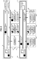
- FIG. 3 is a schematic diagram showing the configuration of the banknote handling system as viewed from above.
- a plurality of banknote sorting areas 40 (40a to 40c) are provided as indicated by broken lines in FIG. 3 .
- banknote handling apparatuses 23 23a to 23c
- loading apparatuses 10 10a to 10c
- the loading apparatus 10 controls the arm unit 11 shown in FIG. 2 to execute a banknote taking-out process, a banknote loading process, etc.
- a plurality of banknote loading areas 42 (42a to 42c) are provided as indicated by broken lines between the container transport lane 51 and the cassette transport lane 52.
- loading apparatuses 10 (10d to 10f) are provided.
- FIG. 3 shows three banknote sorting areas 40 and three banknote loading areas 42 for convenience of description.
- the numbers of the banknote sorting areas 40 and the banknote loading areas 42 are determined based on the number of banknotes to be handled, the handling speed of the banknote handling apparatus 23, the banknote handling speed of the loading apparatus 10, etc.
- FIG. 3 shows containers 24 (24a to 24h) and cassettes 25 (25a to 25e) which are needed for description.
- the number of containers 24 to be transported on the container transport lane 51 and the number of cassettes 25 to be transported on the cassette transport lane 52 are not particularly limited.
- the numbers of containers 24 and cassettes 25 to be actually transported are determined depending on the number of banknotes to be handled, the handling speeds of the banknote handling apparatus 23 and the loading apparatus 10, etc.
- the arm unit 11 controlled by the loading apparatus 10 is provided with a camera for recognizing the positions and shapes of the banknote handling apparatus 23, the containers 24, the cassettes 25, etc., and the positions, storage states, etc., of banknotes to be taken out and loaded among them.
- the loading apparatus 10 analyzes an image captured by the camera to realize various handlings by the arm unit 11.
- the technology of controlling a robot arm, by using an image captured with a camera, to hold and/or move an object has conventionally been known, and therefore, detailed description thereof is omitted.
- a container carrying-in/out area shown in the lower-right part of FIG. 3
- an operator performs a work of putting containers 24 on the container transport lane 51, and a work of collecting containers 24 from the container transport lane 51.
- Each container 24 put on the container transport lane 51 is transported and circulated on the loop-shaped transport lane.
- the loading apparatus 10a controls the arm unit 11 to take the empty container 24a from the container transport lane 51 into the area.
- Taking-in process of containers 24 is not limited to be performed by the arm unit 11 of the loading apparatus 10.
- a diverging member may be provided on the transport lane, and containers 24 may be taken in by the diverging member.
- a diverging transport path for taking in containers 24 may be provided on the transport lane, and containers 24 may be taken into the area by controlling the diverging transport path.
- a transport surface of the container transport lane 51 on which containers 24 are transported is substantially leveled with the upper surface of the workbench on which a container 24 is placed in the banknote sorting area 40.
- taking-in and sending-out of containers 24 can be easily performed between the container transport lane 51 and the banknote sorting area 40 by using the arm unit 11.
- the transport surface of the container transport lane 51 on which containers 24 are transported is substantially leveled with the upper surface of the workbench on which a container 24 is placed in the banknote loading area 42.
- taking-in and sending-out of containers 24 can be easily performed between the container transport lane 51 and the banknote loading area 42.
- a transport surface of the cassette transport lane 52 on which cassettes 25 are transported is substantially leveled with the upper surface of the workbench on which a cassette 25 is placed in the banknote loading area 42.
- a storage quantity of banknotes in a container 24 is indicated by a rectangle on the left side of a rectangle indicating the container 24.
- a blank rectangle of the container 24a indicates that the container 24a is empty.
- a black rectangle of the container 24d indicates that loading of banknotes into the container 24d has been completed and a predetermined number of banknotes are stored in the container 24d.
- a half-white and half-black rectangle of the container 24b indicates that loading of banknotes into the container 24b has been started and is being continued until a predetermined number of banknotes are stored in the container 24b.
- a storage quantity of banknotes in a cassette 25 is also indicated by a rectangle on the left side of a rectangle indicating the container 25.
- a banknote sorting process is performed by the banknote handling apparatus 23.
- an operator places a large number of banknotes in a receptacle of the banknote handling apparatus 23.
- the banknote handling apparatus 23 feeds the banknotes in the receptacle one by one into inside the apparatus, and recognizes and counts the banknotes.
- the banknote handling apparatus 23 stacks, in a stacking unit, banknotes that conform with a preset condition set for banknotes to be stored in a cassette 25.
- banknotes in a good enough condition (fit notes) to be used for a dispensing process in an ATM are sorted and stacked in a plurality of stacking units according to the face/back orientation thereof.
- the banknote handling apparatus 23 sorts the banknotes by denominations and stacks the sorted banknotes in the stacking units by denominations.
- the loading apparatus 10b controls the arm unit 11 to take out the banknotes stacked in the stacking units of the banknote handling apparatus 23b and load the banknotes into the container 24b. For example, when a stacking unit has been filled up with banknotes, the banknote handling apparatus 23 suspends stacking of banknotes into this stacking unit. Upon recognizing this situation, the loading apparatus 10 takes out all the banknotes from the stacking unit in the filled-up state, and loads the taken-out banknotes into the container 24b.
- the banknote handling apparatus 23 suspends stacking of banknotes into this stacking unit.
- the loading apparatus 10 takes out all the banknotes from the stacking unit stacked with the predetermined number of banknotes, and loads the taken-out banknotes into the container 24b.
- the banknote handling apparatus 23 detects that this stacking unit becomes empty, by using a banknote detection sensor provided in the stacking unit.
- the banknote handling apparatus 23 resumes stacking of banknotes into the empty stacking unit.
- the process of loading the predetermined number of banknotes that satisfy the predetermined condition into the storage spaces of the container 24 is automatically performed.
- the loading apparatus 10 can load banknotes into all the storage spaces.
- the loading apparatus 10c controls the arm unit 11 to send out the container 24c in which the banknotes are stored, to the container transport lane 51 as shown by an arrow in the banknote sorting area 40c in FIG. 3 .
- the container 24c sent out to the container transport lane 51 is transported leftward.
- the transport direction of the container 24d is inverted.
- the container 24d the transport direction of which has been inverted, is transported rightward.
- the loading apparatus 10d controls the arm unit 11 to take the container 24e, in which banknotes are stored and which has passed through the inversion unit 41a and is transported rightward, into the area 42a.
- a cassette carrying-in area 45 shown in the upper-right part of FIG. 3 an operator performs a work of putting empty cassettes 25 on the cassette transport lane 52.
- the cassettes 25 put by the operator are transported leftward.
- the loading apparatus 10d controls the arm unit 11 to take the empty cassette 25a, which is transported leftward on the cassette transport lane 52, into the area 42a.
- each banknote loading area 42 a process of taking out banknotes from a container 24 and loading the banknotes into a cassette 25, is performed. As shown by arrows in the banknote loading area 42b in FIG. 3 , the loading apparatus 10e controls the arm unit 11 to take out banknotes from the container 24f and load the banknotes into the cassette 25b.
- the loading apparatus 10 can take out banknotes from all the storage spaces of the container 24 and load the banknotes into a cassette 25.
- the loading apparatus 10 can load banknotes into all the storage spaces of the cassette 25.
- the loading apparatus 10f controls the arm unit 11 to send out the empty container 24g to the container transport lane 51 as shown by an arrow in the banknote loading area 42c in FIG. 3 .
- the loading apparatus 10f sends out the container 25c already loaded with the banknotes to the cassette transport lane 52 as shown by an arrow in the banknote loading area 42c.
- the number of banknotes equivalent to the number of banknotes to be stored in one cassette 25 are stored in each container 24.
- 500 banknotes are stored in each of six storage spaces of one container 24, in other words, 3000 banknotes in total are stored in the container 24.
- the banknote loading area 42 all the banknotes are taken out from the container 24 and are loaded into one empty cassette 25.
- the container 24 becomes empty, and simultaneously, the cassette 25 is loaded with the predetermined number of banknotes. Thereafter, the empty container 24 is sent out to the container transport lane 51, while the cassette 25 having been loaded with the banknotes is sent out to the cassette transport lane 52.
- the transport direction of the container 24h is inverted.
- the container 24h, the transport direction of which has been inverted is transported leftward.
- the container transport lane 51 which is a loop-shaped transport lane, transports and circulates containers 24 clockwise.
- a container 24, which has become empty because banknotes have been taken out therefrom in the banknote loading area 42 is continuously transported to be used again for storage of banknotes in the banknote sorting area 40.
- an empty container 24, which has not been taken into the banknote sorting area 40 is continuously transported and circulated as it is.
- This empty container 24 can be taken into the banknote sorting area 40 when needed to be used for storage of banknotes.
- the transport direction of the cassette 25d is inverted.
- the cassette 25d, the transport direction of which has been inverted, is transported rightward.
- the cassette 25e which is transported rightward on the cassette transport lane 52, has arrived at the left end of the transport lane, the cassette 25e is collected by an operator at a cassette carrying-out area 46.
- the cassette 25 collected by the operator is conveyed to a place where an ATM is installed, and is mounted to the ATM to be used for the dispensing process.
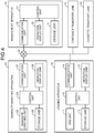
- FIG. 4 is a block diagram showing the configuration of the banknote handling system.
- the loading apparatus 10, the banknote handling apparatus 23, the container transport lane 51, and the cassette transport lane 52 are communicably connected to the management apparatus 30 via a network 50. Since the loading apparatuses 10a to 10f shown in FIG. 3 have the same configuration, one loading apparatus 10 is shown in FIG. 4 . Likewise, since the banknote handling apparatuses 23a to 23c shown in FIG. 3 have the same configuration, one banknote handling apparatus 23 is shown in FIG. 4 .
- the management apparatus 30 can control the banknote handling apparatus 23, the loading apparatus 10, the container transport lane 51, the cassette transport lane 52, etc.
- the banknote handling apparatus 23 includes a control unit 124, a banknote handling unit 125, a memory 126, a communication unit 127, and an operation display unit 128.
- the banknote handling unit 125 feeds a plurality of banknotes received in a receptacle into the apparatus one by one, recognizes and counts the fed banknotes, and performs reading of serial numbers, etc. Then, the banknote handling unit 125 sorts and stacks the banknotes into a plurality of stacking units by denominations.
- the communication unit 127 transmits/receives data to/from the loading apparatus 10 and the management apparatus 30 via the network 50.
- the operation display unit 128 is, for example, a touch panel type liquid crystal display device, and is used for operations such as preparation, confirmation, modification of settings regarding the operation of the banknote handling unit 125.
- the operation display unit 128 is used for an operation of instruction, such as start of banknote handling, performed by an operator.
- the control unit 124 receives the operations performed by using the operation display unit 128 and controls the banknote handling unit 125 on the basis of various settings stored in the memory 126 to perform processes such as recognition and counting of banknotes and reading of serial numbers.
- the memory 126 is, for example, a semiconductor memory, and stores therein various data and programs regarding banknote handling. In addition, the memory 126 is used for storage of the banknote data 121 shown in FIG. 1 .
- the banknote data 121 includes: the number of banknotes being stacked in each stacking unit; and the denomination, fitness/unfitness, face/back orientation, top/bottom orientation, serial number, etc., of each banknote.
- the management apparatus 30 includes a control unit 31, a communication unit 32, an operation display unit 33, and a memory 34.
- the communication unit 32 transmits/receives data to/from the banknote handling apparatus 23 and the loading apparatus 10 via the network 50.
- the operation display unit 33 is, for example, a touch panel type liquid crystal display device, and is used for operations such as preparation, confirmation, and modification of settings regarding the operation of the banknote handling system.
- the operation display unit 33 is also used for operations such as checking of the stored-banknote data 130, etc.
- the memory 34 is, for example, a semiconductor memory, and stores therein various data and programs regarding the operation of the banknote handling system. In addition, the memory 34 is used for storage of the banknote data 121 and the stored-banknote data 130 shown in FIG. 1 .
- the loading apparatus 10 includes the arm unit 11, a control unit 12, a memory 13, a communication unit 14, and an operation display unit 15.
- the communication unit 14 transmits/receives data to/from the banknote handling apparatus 23 and the management apparatus 30 via the network 50.
- the memory 13 is, for example, a semiconductor memory, and stores therein various data and programs regarding control and operation of the arm unit 11.
- the operation display unit 15 is, for example, a touch panel type liquid crystal display device, and is used for, for example, operations such as preparation, confirmation, and modification, of settings regarding the operation of the arm unit 11.
- the operation display unit is also used for operations such as instruction regarding the operation of the arm unit 11, etc.
- the control unit 12 analyzes an image captured by the camera of the arm unit 11, and controls the arm unit 11 on the basis of the settings stored in the memory 13, thereby realizing various operations by the arm unit 11.
- the loading apparatus 10 in the banknote sorting area 40 detects a stacking unit that has been filled with banknotes or a stacking unit that has been loaded with a predetermined number of banknotes in the banknote handling apparatus 23.
- the loading apparatus 10 performs a banknote taking-out process. Detection of the stacking unit to be subjected to the taking-out process is performed by using, for example, a notification process by the banknote handling apparatus 23.
- the banknote handling apparatus 23 notifies the operator of this fact by using the operation display unit 128, a notification lamp, or the like.
- the notification to the operator is performed by displaying, on the operation display unit 128 of the banknote handling apparatus 23, information indicating the stacking unit that needs banknotes to be taken out.
- the notification to the operation is performed by using a notification lamp such as an LED provided to each stacking unit, specifically, by lighting or flashing the notification lamp of the stacking unit from which banknotes need to be taken out.
- the loading apparatus 10 recognizes presence/absence of notification on the basis of an image of the banknote handling apparatus 23 captured by the camera of the arm unit 11.
- the loading apparatus 10 recognizes the fact that there is a stacking unit that needs banknotes to be taken out, and the position of this stacking unit.
- the recognition is performed on the basis of the information displayed on the operation display unit 128 and/or the lighting state of the notification lamp.
- the loading apparatus 10 controls the arm unit 11 to execute the banknote taking-out process from the stacking unit and the banknote loading process to a container 24.
- the recognition method of, by the loading apparatus 10, a stacking unit that needs banknotes to be taken out is not limited to the above methods.
- the banknote handling apparatus 23 may transmit, to the loading apparatus 10, information that enables identification of a stacking unit that needs banknotes to be taken out.
- the management apparatus 30 may monitor the stacking states of the respective stacking units of the banknote handling apparatus 23, and transmit, to the loading apparatus 10, information that enables identification of a stacking unit that needs banknotes to be taken out.
- the loading apparatuses 10 in the banknote sorting area 40 and the banknote loading area 42 detect the banknote storage states in the containers 24, and perform taking-in of containers 24 from the container transport lane 51 and sending-out of containers 24 to the container transport lane 51.
- the loading apparatus 10 in the banknote loading area 42 detects the banknote storage states in the cassettes 25, and performs taking-in of cassettes 25 from the cassette transport lane 52 and sending-out of cassettes 25 to the cassette transport lane 52. Detection of the banknote storage states is performed by using identification information of the containers 24 and identification information of the cassettes 25.
- All the containers 24 are given container identification information for distinguishing the containers 24 from each other.
- a barcode obtained by encoding container identification information is affixed to each container 24.
- the loading apparatus 10 obtains the container identification information of each container 24 by reading the barcode with the camera of the arm unit 11.
- setting information in which storage space identification information for distinguishing the storage spaces from each other is stored in the memory 13 of the loading apparatus 10 in advance.
- This setting information includes information indicating correspondence between the position of each storage space and the storage space identification information with reference to the barcode affixation position.
- the loading apparatus 10 recognizes the positional relationship between the barcode affixation position and each storage space from the image captured by the camera, and specifies the storage space identification information of each storage space.
- barcodes which are obtained by encoding cassette identification information for distinguishing the cassettes 25 from each other are affixed to all the cassettes 25.
- the loading apparatus 10 obtains the cassette identification information of each cassette 25 by reading the barcode with the camera of the arm unit 11. Also, when a cassette 25 includes a plurality of storage spaces, the loading apparatus 10 recognizes storage space identification information of each storage space on the basis of the positional relationship between the barcode affixation position and each storage space, as in the case of the containers 24.
- the operator When the operator puts an empty container 24 on the container transport lane 51, the operator reads the barcode affixed to the empty container 24 with a barcode reader, and transmits the obtained container identification information to the management apparatus 30. Likewise, when the operator puts an empty cassette 25 on the cassette transport lane 52, the operator reads the cassette identification information from the cassette 25 with a barcode reader, and transmits the obtained cassette identification information to the management apparatus 30.
- the loading apparatus 10 in the banknote sorting area 40 obtains the container identification information of the empty container 24 from the management apparatus 30. Then, the loading apparatus 10 reads the barcodes of the containers 24 being transported on the container transport lane 51 by using the camera of the arm unit 11 to detect the empty container 24. This allows the empty container 24 to be taken into the banknote sorting area 40 as described above.
- the loading apparatus 10 in the banknote loading area 42 obtains the cassette identification information of the empty cassette 25 from the management apparatus 30. Then, the loading apparatus 10 reads the barcodes of the cassettes 25 being transported on the cassette transport lane 52 by using the camera of the arm unit 11 to detect the empty cassette 25. This allows the empty cassette 25 to be taken into the banknote loading area 42 as described above.
- the management apparatus 30 manages information such as the kind and the number of banknotes to be loaded into each cassette 25.
- the management apparatus 30 transmits information regarding banknotes to be loaded into a cassette 25 by the loading apparatus 10 in the banknote loading area 42, to this loading apparatus 10.
- the management apparatus 30 specifies a container 24 in which banknotes of the kind to be loaded into the cassette 25 are stored, and transmits the container identification information of this container 24 to the loading apparatus 10.
- the loading apparatus 10 Upon receiving the container identification information, the loading apparatus 10 reads the barcodes of the containers 24 being transported on the container transport lane 51 by using the camera of the arm unit 11, and detects the container 24 in which banknotes of the kind to be loaded into the cassette 25 are stored. This enables the process of taking a container 24 already loaded with banknotes into the banknote loading area 42, and loading a cassette 25 with the banknotes taken out from this container 24, as described above.
- the loading apparatus 10 in the banknote sorting area 40 transmits loading data 110 to the management apparatus 30 as shown in FIG. 1B .
- the loading data 110 includes: information that specifies the stacking unit, in the banknote handling apparatus 23, from which the banknotes have been taken out; and container identification information and storage space identification information that specify the storage space of the container 24 that has been loaded with the taken-out banknotes.
- the management apparatus 30 obtains information about the banknotes taken out from the stacking unit in the banknote handling apparatus 23.
- the loading data 110 further includes information indicating the movement of the arm unit 11.
- the management apparatus 30 specifies the orientation of the banknotes loaded into the storage space of the container 24, based on the face/back orientation and the top/bottom orientation of the banknotes having been stacked in the stacking unit, and on the movement of the arm unit 11.
- the management apparatus 30 generates stored-banknote data 130 of banknotes loaded into a container 24, based on banknote data 121 regarding banknotes stacked in each stacking unit in the banknote handling apparatus 23.
- the management apparatus 30 can manage correspondence between the serial numbers of banknotes being stored in each storage space of the container 24 and the alignment order of the actual banknotes.
- the generated stored-banknote data 130 includes: the number of banknotes stored in each storage space of the container 24; and the denomination, fitness/unfitness, face/back orientation, top/bottom orientation, serial number, etc., of each banknote.
- the stored-banknote data 130 is generated for all the containers 24 that are loaded with banknotes by the loading apparatus 10. When the container 24 has a plurality of storage spaces, the stored-banknote data 130 is generated for each storage space.
- the loading apparatus 10 transmits, to the management apparatus 30, container identification information that specifies a container 24 and storage space identification information that specifies a storage space, of the container 24, which is loaded with banknotes. Using these pieces of information, the management apparatus 30 generates and manages stored-banknote data 130 for each storage space of each container 24.
- the loading apparatus 10 in the banknote loading area 42 transmits loading data 110 to the management apparatus 30.
- the loading data 110 includes: container identification information and storage space identification information that specify a storage space, of the container 24, from which the banknotes have been taken out; and cassette identification information and storage space information that specify a storage space, of the cassette 25, which is loaded with the banknotes taken out from the container 24. Further, the loading data 110 includes information indicating the movement of the arm unit 11.
- the management apparatus 30 specifies the orientation of the banknotes loaded into the storage space in the cassette 25, based on the face/back orientation and the top/bottom orientation of the banknotes having been stored in each storage space of the container 24, and on the movement of the arm unit 11.
- the management apparatus 30 generates stored-banknote data 130 regarding banknotes loaded into a cassette 25, based on banknote data 121 regarding banknotes being stored in each storage space of a container 24. That is, in the banknote loading area 42, stored-banknote data 130 is generated for the cassette 25 by using, as banknote data 121, the stored-banknote data 130 previously generated for the container 24 in the banknote sorting area 40.
- the management apparatus 30 can manage correspondence between the serial numbers of the banknotes loaded into each storage space of each cassette 25, and the alignment order of the actual banknotes.
- the generated stored-banknote data 130 includes: the number of banknotes stored in each storage space of the cassette 25; and the denomination, fitness/unfitness, face/back orientation, top/bottom orientation, serial number, etc., of each banknote.
- the stored-banknote data 130 is generated for all the cassettes 25 that are loaded with banknotes by the loading apparatus 10. When the cassette 25 has a plurality of storage spaces, the stored-banknote data 130 is generated for each storage space.
- the loading apparatus 10 transmits, to the management apparatus 30, cassette identification information that specifies a cassette 25, and storage space identification information that specifies a storage space, of the cassette 25, which is loaded with banknotes. Using these pieces of information, the management apparatus 30 generates stored-banknote data 130 for each storage space in each cassette 25 and manages the generated store-banknote data 130.
- the method of obtaining the identification information of containers 24 and cassettes 25 is not limited to the method of using codes such as barcodes.
- wireless communication tags such as IC tags, in which identification information of a container 24/cassettes 25 is stored, may be affixed to the container 24/cassette 25, and the identification information may be obtained by using an IC tag reader mounted to the arm unit 11 of the loading apparatus 10.
- the IC tag readers may be provided on the container transport lane 51 and the cassette transport lane 52.
- predetermined marks are affixed to reference positions on each container 24 and each cassette 25.
- Each storage space in the container 24 and each storage space in the cassette 25 can be identified on the basis of the positional relationship between each storage space and the affixed mark captured by the camera of the arm unit 11, whereby the storage states of banknotes in each storage space can be managed.
- FIG. 5 shows an external appearance of a banknote sorting area 40.
- banknotes to be loaded into a container 24 are prepared by using a banknote handling apparatus 23 having four open stacking units, and the banknotes prepared in the banknote handling apparatus 23 are loaded into six storage spaces of the container 24.
- a rotatable hand assembly 11a is mounted to a distal end of an arm unit 11 of a loading apparatus 10.
- the hand assembly 11a includes two holding members. The distance between the plate-shaped holding members is controlled by using an actuator, thereby allowing the hand assembly 11a to hold an object.
- the loading apparatus 10 uses the hand assembly 11a to hold banknotes, which are stacked in a bundle form in a stacking unit of the banknote handling apparatus 23, by sandwiching these banknotes from both outer sides thereof. Then, the held banknotes in the bundle form are moved and loaded into each storage space of the container 24.
- FIG. 6 shows an external appearance of a banknote loading area 42.
- a container 24 is taken-in and placed at a position on the container transport lane 51 side while a cassette 25 is taken-in and placed at a position on the cassette transport lane 52 side.
- a lid 26 is mounted to the cassette 25.
- the loading apparatus 10 controls an arm unit 11 to remove the lid 26 from the cassette 25 and put the lid 26 on the workbench.
- the loading apparatus 10 causes a banknote storage space inside the cassette 25 to be exposed before starting loading of banknotes.
- a rotatable hand assembly 11a is mounted to a distal end of the arm unit 11 of the loading apparatus 10.
- the hand assembly 11a includes two holding members.
- the distance between the plate-shaped holding members is controlled by using an actuator, thereby allowing the hand assembly 11a to hold an object.
- the loading apparatus 10 uses the hand assembly 11a to hold banknotes, which are stacked in a bundle form in a storage space of the container 24, by sandwiching these banknotes from both outer sides thereof. Then, the held banknotes in the bundle form are moved and loaded into the storage space of the cassette 25.
- the loading apparatus 10 controls the arm unit 11 to mount the lid 26 to the cassette 25. Then, the loading apparatus 10 sends out the cassette 25 to the cassette transport lane 52.
- FIG. 7 is a schematic diagram showing a banknote taking-out process and a banknote loading process performed in the banknote handling system.
- FIG. 7a is a schematic diagram showing the banknote taking-out process and the banknote loading process performed in the banknote sorting area 40 by the loading apparatus 10.
- the banknote handling apparatus 23 prepares, by using a plurality of stacking units, a plurality banknotes 101 to 103 to be stored in storage spaces 224 of a container 24.
- the loading apparatus 10 sequentially takes out the banknotes 101 to 103 in bundle forms which are prepared in the respective stacking units of the banknote handling apparatus 23, and loads the banknotes into the respective storage spaces 224 of the container 24.
- This process is not necessarily performed by a single arm unit 11 as shown in FIG. 5 , but may be performed by a plurality of arm units 11 as shown in FIG. 7A .
- FIG. 7B is a schematic diagram showing the banknote taking-out process and the banknote loading process performed in the banknote loading area 42 by the loading apparatus 10.
- the loading apparatus 10 sequentially takes out banknotes 201, which have been stored in the storage spaces 224 of the container 24 in the banknote sorting area 40 as shown in FIG. 7A , and loads the banknotes into storage spaces 225 of a cassette 25.
- This process is not necessarily performed by a single arm unit 11 as shown in FIG. 6 , but may be performed by a plurality of arm units 11 as shown in FIG. 7 .
- the banknote handling apparatus 23 can stack banknotes with uniform face/back orientation in each stacking unit.
- the management apparatus 30 manages the face/back orientation of banknotes that have been taken out from a stacking unit and loaded into a container 24, based on information regarding the banknotes stacked in the stacking unit and on information indicating the movement of the arm unit 11 of the loading apparatus 10 in the banknote sorting area 40.
- the face/back orientation of the banknotes to be loaded into a cassette 25 can be made uniform as described in FIG. 1 .
- the loading apparatus 10 when the loading apparatus 10 is set to make the face/back orientation of the banknotes to be loaded into the cassette 25 uniform, the loading apparatus 10 recognizes the face/back orientation of the banknotes stored in each storage space of the container 24. When loading the banknotes taken out from the container 24 into the cassette 25, the loading apparatus 10 controls the arm unit 11 to reverse the face/back orientation of the banknotes according to need. Thus, the face/back orientations of all the banknotes loaded into the cassette 25 can be made uniform.
- the banknote handling apparatus 23 can also stack banknotes with uniform face/back orientation and uniform top/bottom orientation in each stacking unit. That is, as in the case of making the face/back orientation uniform, the banknote handling apparatus 23 can make the top/bottom orientations of all the banknotes to be loaded into the cassette 25 uniform by controlling the loading apparatus 10.
- the banknotes 101 to 103 in the bundle forms prepared in the banknote handling apparatus 23 may be directly loaded into a cassette 25 without using a container 24.
- FIG. 7C shows a process in which the loading apparatus 10 sequentially takes out the banknotes 101 to 103 in the bundle forms prepared in the banknote handling apparatus 23, and directly loads the banknotes into the storage spaces 225 of the cassette 25.
- the number of arm units 11 used by the loading apparatus 10 is not limited, and may be one or more.
- the management apparatus 30 can generate stored-banknote data 130, which allows the serial numbers of the banknotes 202 stored in each storage space 225 of the cassette 25 to be specified, from the banknote data 121 including the serial numbers, etc., of the banknotes 101 to 103 prepared in the banknote handling apparatus 23.
- FIG. 8 is a schematic diagram showing an example of a banknote handling system in which banknote binding apparatuses 123 (123a to 123c) are installed in the respective banknote sorting areas 40.
- FIG. 9 is a block diagram showing the configuration of the banknote handling system shown in FIG. 8 .
- a banknote-bundle transport lane 53 and a large-bundle formation apparatus 223 are connected to the management apparatus 30.
- the management apparatus 30 can control the container transport lane 51, the cassette transport lane 52, the banknote-bundle transport lane 53, the loading apparatus 10, the banknote handling apparatus 23, the banknote binding apparatus 123, the large-bundle formation apparatus 223, etc.
- the banknote handling system shown in FIG. 8 is different from the banknote handling system shown in FIG. 3 in that the banknote handling apparatus 23 in each banknote sorting area 40 is connected to the banknote binding apparatus 123, that the banknote-bundle transport lane 53 for transporting banknote bundles 27 formed by each banknote binding apparatus 123 is provided, and that the large-bundle formation apparatus 223 is provided at an end of the banknote-bundle transport lane 53.
- the banknote handling apparatus 23 and the banknote binding apparatus 123 are connected to each other, so that banknotes recognized and counted in the banknote handling apparatus 23 can be sent to the banknote binding apparatus 123 to be stored in a predetermined storing unit in the banknote binding apparatus 123.
- a predetermined number e.g. 100
- the banknote binding apparatus 123 binds these banknotes with a band to form a banknote bundle 27.
- the banknote binding apparatus 123 discharges the banknote bundle 27 onto the banknote-bundle transport lane 53.
- the banknote bundle 27 discharged onto the banknote-bundle transport lane 53 is transported rightward to the large-bundle formation apparatus 223.
- the large-bundle formation apparatus 223 takes the banknote bundle 27 being transported on the banknote-bundle transport lane 53 into the apparatus, and stores the banknote bundle 27 in a predetermined storing unit. When the number of stored banknote bundles 27 has reached a predetermined number (e.g., 10), the large-bundle formation apparatus 223 binds these banknote bundles 27 with a band to form a large bundle.
- a predetermined number e.g. 10
- the banknote bundles 27 may be discharged one by one from the banknote binding apparatus 123 onto the banknote-bundle transport lane 53.
- a predetermined number e.g., 10
- banknote bundles 27 may be temporarily bound with a band in the banknote handling apparatus 23 and discharged in the temporarily bound state onto the banknote-bundle transport lane 53.
- the banknote handling apparatus 23 stacks, in the stacking units, banknotes in good condition (fit notes) which can be used for a dispensing process in an ATM, as banknotes to be loaded into cassettes 25. Meanwhile, the banknote handling apparatus 23 sends banknotes in bad condition (unfit notes) to the banknote binding apparatus 123.
- the banknote binding apparatus 123 which has received the unfit notes, binds 100 unfit notes to form a banknote bundle 27.
- the large-bundle formation apparatus 223 binds ten banknote bundles 27, which have been received from the banknote binding apparatuses 123 through the banknote-bundle transport lane 53, to form a large bundle.
- containers 24 are sent out from the banknote sorting areas 40 to the container transport lane 51 and transported to the banknote loading areas 42.
- the banknote handling system may be set as follows. That is, a container 24 sent out from a banknote sorting area 40 to the container transport lane 51 is taken into another banknote sorting area 40 and subjected to banknote handling, and thereafter, this container 24 is sent out to the container transport lane 51 again and transported to a banknote loading area 42.
- the first banknote sorting area 40 eight kinds of banknotes D1 to D8 are sorted into “banknotes D1 and banknotes D2", “banknotes D3 and banknotes D4", “banknotes D5 and banknotes D6", and “banknotes D7 and banknotes D8".
- the sorted banknotes are stacked in four stacking units of the banknote handling apparatus 23, respectively.
- the loading apparatus 10 in the first banknote sorting area 40 takes out the stacked banknotes from the four stacking units and loads the banknotes into four storage spaces, respectively, of a container 24 having eight storage spaces.
- two kinds of banknotes are stored in a mixed state in each of the four storage spaces among the eight storage spaces of the container 24, while the remaining four storage spaces remain empty.
- the loading apparatus 10 sends out this container 24 to the container transport lane 51.
- the loading apparatus 10 takes the container 24, which has been sent from the first banknote sorting area 40, from the container transport lane 51 into the area.
- the loading apparatus 10 takes out the banknotes D1 and the banknotes D2 in a mixed bundle form, from the container 24, and places the banknotes in the receptacle of the banknote handling apparatus 23 installed in the second banknote sorting area 40.
- the loading apparatus 10 takes out the banknotes D3 and the banknotes D4 in a mixed bundle form, from the container 24, and places the banknotes in the receptacle of the banknote handling apparatus 23.
- the banknote handling apparatus 23 detects the placement of the banknotes with a banknote detection sensor provided to the receptacle.
- the banknote handling apparatus 23 feeds the banknotes from the receptacle one by one into inside the apparatus, and recognizes and counts the banknotes. By using the four stacking units, the banknote handling apparatus 23 sorts and stacks the banknotes D1, the banknotes D2, the banknotes D3, and the banknotes D4 in the respective stacking units.
- the loading apparatus 10 takes out the banknotes from the four stacking units of the banknote handling apparatus 23, and loads the banknotes into the empty storage spaces of the container 24.
- the loading apparatus 10 takes out the banknotes D5 and the banknotes D6 in a mixed bundle form, from the container 24, and places the banknotes in the receptacle of the banknote handling apparatus 23.
- the loading apparatus 10 takes out the banknotes D7 and the banknotes D8 in a mixed bundle form, from the container 24, and places the banknotes in the receptacle of the banknote handling apparatus 23.
- the loading apparatus 10 takes out the banknotes from the respective stacking units and loads the banknotes into the empty storage spaces of the container 24.
- the banknotes D1 to D8 are loaded by kinds into the eight storage spaces of the container 24, respectively.
- the loading apparatus 10 sends out this container 24 to the container transport lane 51.
- the loading apparatus 10 in the first banknote loading area 42 takes this container 24 into the area, and loads the banknotes stored in the container 24 into a cassette 25.
- the loading apparatus 10 may be set as follows. That is, after only a part of the banknotes is taken out from the container 24 and loaded into a first cassette 25, this container 24 is sent out to the container transport lane 51, and the remaining banknotes are taken out from the container 24 and loaded into a second cassette 25 in the second banknote loading area 42.
- banknotes are sorted by kinds in the two banknote sorting areas 40, and predetermined kinds of banknotes are loaded in each cassette 25 in the two banknote loading areas 42.
- the number of the banknote sorting areas 40 and the number of the banknote loading areas 42 may be three or more.
- banknotes in which banknotes of four denominations (first to fourth denominations) are mixed with random face/back orientations, are sorted by denominations and by orientations (face/back) in the banknote sorting area 40.
- the banknotes are sorted and stacked by denominations in the four stacking units.
- the banknotes are loaded by denominations into four storage spaces of a container 24, and the container 24 is sent to the second banknote sorting area 40.
- banknotes of the same denomination are stored in each of the four storage spaces, face-up banknotes and face-down banknotes are mixed in each storage space.
- the banknotes of each denomination are sorted according to the face/back orientation, and stacked face-up banknotes and face-down banknotes separately.
- the banknotes of four denominations can be loaded by denominations with uniform face/back orientation into the eight storage spaces of the container 24.
- the banknotes are loaded by denominations with uniform face/back orientation into four cassettes 25, i.e., first to fourth cassettes 25.
- the face-up banknotes of the first denomination are loaded as they are into the first cassette 25, while the face-down banknotes of the first denomination are loaded into the first cassette 25 after reversing the face/back orientation.
- the container 24 is sent to the second banknote loading area 42.
- the second to fourth banknote loading areas 42 a process of loading the banknotes of the same denomination with uniform face/back orientation is also performed for the second to fourth cassettes 25, respectively.
- the banknotes of the first to fourth denominations can be loaded by denominations with uniform face/back orientation into the first to fourth cassettes 25, respectively.
- the method of making the face/back orientation of the banknotes to be loaded into a cassette 25 uniform is not limited to the method of reversing, according to need, the banknotes to be loaded into the cassette 25 by the loading apparatus 10 in the banknote loading area 42.
- the loading apparatus 10 in the banknote sorting area 40 may reverse, according to need, the banknotes to be loaded into a container 24 to make the face/back orientation uniform.
- the stored-banknote data 130 generated by the management apparatus 30 is stored in the memory 34 of the management apparatus 30.
- the storage location of the stored-banknote data 130 is not particularly limited.
- the stored-banknote data 130 may be stored in a server apparatus or the like connected to the network 50.
- the stored-banknote data 130 may be stored in a portable storage medium such as a memory card.
- the stored-banknote data 130 of banknotes stored in a cassette 25 is stored in a memory card mounted to the cassette 25.
- the ATM can use the stored-banknote data 130 read from the memory card.
- all the plurality of storage spaces of each container 24 are loaded with banknotes.
- only part of the storage spaces may be loaded with banknotes.
- the banknote sorting area 40 only part of the storage spaces provided in a container 24 is loaded with banknotes, and the container 24 is sent out to the container transport lane 51.
- the banknote loading area 42 if the container 24 becomes empty before a predetermined number of banknotes are loaded into a cassette 25, the loading apparatus 10 sends out the empty container 24 to the container transport lane 51, with the cassette 25 being left as is.
- the loading apparatus 10 takes another container 24 in which banknotes are stored, from the container transport lane 51 into the banknote loading area 42.
- the loading apparatus 10 loads banknotes taken out from this container 24 into the cassette 25. If banknotes are left in the container 24 after the predetermined number of banknotes have been loaded into the cassette 25, the loading apparatus 10 sends out the cassette 25 having been loaded with banknotes to the cassette transport lane 52, with the container 24 being left as is.
- the operator in the cassette carrying-in area 45 puts an empty cassette 25 on the cassette transport lane 52.
- the loading apparatus 10 which has sent out the cassette 25 having been loaded with banknotes to the cassette transport lane 52, takes the empty cassette 25 being transported on the cassette transport lane 52 into the banknote loading area 42, and starts a process of loading the banknotes left in the container 24 into this cassette 25.
- the predetermined number of banknotes can be loaded into the cassette 25.
- the loading apparatus 10 reverses the face/back orientation of taken-out banknotes according to need, thereby making the face/back orientation of the banknotes to be loaded uniform.
- the banknote handling apparatus 23 can recognize not only the face/back orientation of each banknote but also the top/bottom orientation of each banknote.
- the banknote handling apparatus 23 sorts and stacks banknotes by top/bottom orientations, and the loading apparatus 10 reverses, according to need, the top/bottom orientation of the banknotes when loading these banknotes.
- the top/bottom orientation of the banknotes loaded into the second storage unit 22 shown in FIG. 1 can be made uniform.
- the banknote handling system when loading a container 24 or a cassette 25 with banknotes, at least one of the face/back orientation and the top/bottom orientation can be made uniform.
- the order of the serial numbers included in the banknote data 121 is changed according to the actual banknotes as shown in FIG. 1C .
- banknotes which have a part that has a different thickness from the other part.
- the orientation of the banknotes can be reversed to prevent a region of the stack of banknotes from being larger in height than the other region.
- the kind of the banknotes which have a part that has a different thickness, the number of the banknotes, and the loading method for the banknotes are set in advance, and thus the loading apparatus 10 executes loading of the banknotes into a cassette 25, based on the settings.
- the loading apparatus 10 when loading the banknotes of the set kind into the cassette 25, the loading apparatus 10 changes at least one of the face/back orientation and the top/bottom orientation of the banknotes, based on the set loading method, each time the number of the banknotes loaded in the same orientation has reached a set number. Changing the face/back orientation and/or the top/bottom orientation is performed such that the thicker regions do not overlap each other. For example, the loading apparatus 10 loads the banknotes into the cassette 25 while changing the orientation of the banknotes according to need, such that the thicker region of the banknotes is on the right side when loaded into the cassette 25.
- the loading apparatus 10 changes, according to need, the orientation of the banknotes such that the thicker region of the banknotes is on the left side. After 500 banknotes have been loaded in this state, the loading apparatus 10 again changes the orientation of the banknotes such that the thick region is on the right side. Repeating this loading operation prevents the thicker region of the banknotes from being concentrated on one side in the cassette 25, whereby the banknotes can be loaded such that the right and left heights of the banknotes become almost uniform. This loading operation may be performed based on settings prepared by using the operation display unit 15, or may be performed by the loading apparatus 10 under control of the management apparatus 30.
- stored-banknote data 130 is generated by using storage space identification information for distinguishing the storage spaces from each other.
- stored-banknote data 130 may be generated based on storage space position information.
- banknote data 121 of the respective storage spaces are managed in association with the positions of the left, center, and right storage spaces. It is assumed that the loading apparatus 10 takes out banknotes from each of the three storage spaces and loads the banknotes into a cassette 25 in the loading order of banknotes in the center storage space, banknotes in the right storage space, and banknotes in the left storage space.
- the loading apparatus 10 transmits information indicating this loading order as loading data 110 to the management apparatus 30.
- the management apparatus 30 recognizes that the banknotes loaded into the cassette 25 are banknotes obtained by stacking the banknotes in the center storage space, the banknotes in the right storage space, and the banknotes in the left storage space. Then, the management apparatus 30 generates stored-banknote data 130 by combining banknote data 121 corresponding to the center storage space, banknote data 121 corresponding to the right storage space, and banknote data 121 corresponding to the left storage space in this order.
- the banknote data 121 is managed in association with the position information of each storage space, and the order of the loaded banknotes is input, as the order of the storage spaces, into the management apparatus 30, thereby generating stored-banknote data 130 which allows the serial numbers of all the banknotes in the cassette 25 to be specified according to the alignment order of the banknotes in the cassette 25.
- banknotes For example, it is also possible to perform loading of banknotes into a cassette 25 according to the kind and storage state of banknotes stored in storage spaces of a container 24 to generate stored-banknote data 130.
- a plurality of banknotes each having a part that has a different thickness from the other part, are stacked in a bundle form and stored in a storage space, there are a case where the left-side thickness of the banknotes is increased and a case where the right-side thickness of the banknotes is increased.
- a plurality of storage spaces are formed in two lines on the right and left sides in a container 24, and banknotes, which will be higher on the left side when the loading apparatus 10 loads them into a cassette 25 without performing a banknote reversing operation, are stored in the left-side line, while banknotes, which will be higher on the right side when loaded as described above, are stored in the right-side line.
- the loading apparatus 10 loads the banknotes into the cassette 25 such that the right and left heights thereof become almost uniform by preventing the thick region of the banknotes from being concentrated on one side in the cassette 25.
- the loading apparatus 10 alternately performs a process of taking out the banknotes from a storage space on the left-side line in the container 24 and loading the banknotes into the cassette 25, and a process of taking out the banknotes from a storage space on the right-side line in the container 24 and loading the banknotes into the cassette 25.
- the loading apparatus 10 transmits, to the management apparatus 30, information indicating the positions of the storage spaces from which the banknotes have been taken out, such as "left-side first stage", "right-side first stage”, etc., as loading data 110.
- the management apparatus 30 receives the banknote data 121 corresponding to the respective storage spaces and combines them in the loading order, thereby generating stored-banknote data 130.
- the loading process can be performed such that a difference in height between the right side and the left side of the banknotes stacked and stored in the cassette 25 is within a predetermined range.
- the loading apparatus 10 controls the arm unit 11 to perform taking-in of containers 24 and cassettes 25 being transported on the transport lanes, and sending-out of containers 24 and cassettes 25 to the transport lanes.
- these processes may be performed by using the transport lanes.
- the container transport lane 51 is provided with a diverging transport path for taking in and out containers 24 between the transport path and each of the banknote sorting area 40 and the banknote loading area 42. Then, the loading apparatus 10 or the management apparatus 30 may control the diverging transport path to realize taking of containers 24 into each area and sending-out of containers 24 from each area.
- the cassette transport lane 52 is provided with a diverging transport path for taking in and out cassettes 25 between the transport path and each banknote loading area 42. Then, the loading apparatus 10 or the management apparatus 30 controls the diverging transport path to realize taking of cassettes 25 into each area and sending-out of cassettes 25 from each area.
- the loading apparatus 10 obtains information from a barcode or an IC tag affixed to each container 24 by using a camera or an IC tag reader mounted to the arm unit 11.
- information of each container 24 may be obtained by other methods.
- a camera or an IC tag reader may be provided to the container transport lane 51 to obtain information of each container 24.
- the loading apparatus 10 or the management apparatus 30 obtains information from a barcode or an IC tag of each container 24 by using the camera or the IC tag reader provided to the container transport lane 51, thereby specifying a container 24 to be taken into the banknote sorting area 40 and a container 24 to be taken into the banknote loading area 42.
- taking-in of a container 24 into each area can be performed based on the specified result, as described above.
- a meter for measuring the weight of each container 24 may be provided to the container transport lane 51 to obtain information of the container 24. Measuring the weight of a container 24 with the meter provided to the container transport lane 51 enables determination as to whether the container 24 is empty or loaded with banknotes. Then, for example, taking-in of a container 24 loaded with banknotes into the banknote loading area 42 and taking-in of an empty container 24 into the banknote sorting area 40 can be performed based on the determination result, as described above.
- the cassette transport lane 52 has a U shape. However, like the container transport lane 51, the cassette transport lane 52 may be formed in a loop shape so that cassettes 25 are transported and circulated.
- the loop-shaped cassette transport lane 52 allows the above-described function and operation regarding the container transport lane 51 to be achieved also in the cassette transport lane 52.
- a camera, an IC tag reader, a weight meter, or the like which functions as an information acquisition unit, is provided to the arm unit 11 of the loading apparatus 10, the transport lane, or the like. Then, by using the information acquisition unit, the loading apparatus 10 or the management apparatus 30 obtains information regarding cassettes 25 being transported, and specifies a cassette 25 to be taken into the banknote loading area 42.
- the target cassette 25 to be loaded with banknotes is taken into the banknote loading area 42 to start the loading process, whereas a cassette 25 which is not a target is transported and circulated while remaining empty.
- the empty cassette 25 being transported and circulated is taken into the banknote loading area 42 when a container 24 in which banknotes to be loaded into this cassette 25 are stored is taken into the banknote loading area 42.
- the banknotes taken out from the container 24 are loaded into this cassette 25.
- the cassette transport lane 52 may be diverged, at a point downstream of the banknote loading area 42, into a transport path for transporting and circulating empty cassettes 25, and a transport path for transporting cassettes 25 already loaded with banknotes toward the cassette carrying-out area 46.
- the loading apparatus 10 or the management apparatus 30 by using the information acquisition unit, determines whether a cassette 25 being transported on the upstream side of the diverging point is empty or has already been loaded with banknotes. Then, based on the determination result, the loading apparatus 10 or the management apparatus 30 controls the divergence destination, so that the empty cassette 25 is again transported and circulated toward the banknote loading area 42 while the cassette 25 already loaded with banknotes is transported to the cassette carrying-out area 46.
- the cassette 25 already loaded with banknotes can be collected from the cassette carrying-out area 46 while the empty cassette 25 continues to be circulated and transported.
- the banknote handling apparatus 23 in the banknote sorting area 40 recognizes and counts banknotes, and stacks, in a stacking unit, banknotes that can be loaded into a cassette 25.
- the loading apparatus 10 in the banknote sorting area 40 controls the arm unit 11 to take out the banknotes from the stacking unit of the banknote handling apparatus 23 and loads the banknotes into a container 24.
- the container 24 loaded with the banknotes is transported to the banknote loading area 42 through the container transport lane 51.
- the loading apparatus 10 controls the arm unit 11 to take out the banknotes from the container 24 transported from the banknote sorting area 40, and loads the banknotes into a cassette 25.
- the banknotes are reversed, according to need, based on the orientation of the banknotes taken out from the container 24, so that the banknotes can be loaded into the cassette 25 with at least one of the face/back orientation and the top/bottom orientation of the banknotes being made uniform.
- a process of loading a predetermined number of banknotes, which satisfy a predetermined condition, into each of a plurality of cassettes 25 can be accurately performed in a short time.
- a plurality of banknote sorting areas 40 can be provided along the container transport lane 51, and a plurality of banknote loading areas 42 can be provided along both the container transport lane 51 and the cassette transport lane 52.
- the number of the banknote sorting areas 40 and the number of the banknote loading areas 42 are determined such that the number of banknotes that can be handled per unit time by the entire banknote sorting area 40 becomes substantially equal to the number of banknotes that can be handled per unit time by the entire banknote loading area 42.
- a large number of banknotes can be efficiently handled while avoiding the situation that one of the process in the banknote sorting area 40 and the process in the banknote loading area 42 cannot follow the other process.
- banknotes stacked in an aligned state with their faces in parallel with each other can be taken out from a storage case such as a stacking unit of the banknote handling apparatus 23, a container 24, or a cassette 25, and loaded into another storage case such as a container 24 or a cassette 25 while maintaining the aligned state, in the order in which the serial numbers thereof have been read. Then, correspondence between the serial numbers of all the banknotes stored in the storage case and the alignment order of actual banknotes can be managed. Thus, when the banknotes stored in the aligned state in the storage case are fed out one by one, the serial numbers of each fed out banknote can be specified.
- a cassette 25 which is used for storage of banknotes to be used for a dispensing process in an ATM, is loaded with banknotes. This allows the serial numbers of the banknotes dispensed from the ATM to be specified.
- the sheet handling system and the sheet handling method according to the present invention are useful in managing identification information of a plurality of sheets stored in a storage case, and the order of the identification information.
Abstract
Description
- The present invention relates to a sheet handling system and a sheet handling method that handle sheets.
- In recent years, systems in which robots are used for handling sheets have appeared. For example, Patent Literature 1 discloses a system in which a working robot loads a large number of banknotes into cassettes for carrying banknotes. Using the working robot enhances the efficiency of the work of loading the large number of banknotes into the cassettes.
- Serial numbers are printed on banknotes as identification information for the purpose of forgery prevention, etc. Banknotes can be distinguished from each other based on the serial numbers printed thereon. Reading the serial number of a banknote before storing the banknote in a cassette enables strict management of the banknote stored in the cassette, based on the serial number.
- [PTL 1] Japanese Laid-Open Patent Publication No.
2016-224664 - In the conventional art described above, however, the order of the serial numbers of a plurality of banknotes is not managed. The serial numbers of all banknotes stored in a container such as a cassette may be known, but the serial numbers cannot be specified in the alignment order of the banknotes. For example, when banknotes, which are stored in a container so as to be stacked in the up-down direction, are taken out in order from the uppermost banknote, the serial numbers of the banknotes cannot be specified.
- The present invention is made in view of the problem of the conventional art described above, and an object of the present invention is to provide a sheet handling system and a sheet handling method capable of managing identification information of a plurality of sheets stored in a container, and the order of the identification information of each sheet.
- To solve the above problems and achieve the above object, the present invention is provided with: a first storage unit configured to stack sheets; a second storage unit configured to stack the sheets; a loading apparatus configured to execute a loading process of taking out the sheets stacked in the first storage unit, and loading the taken-out sheets into the second storage unit while maintaining a stacked state of the sheets; and a management apparatus configured to generate second data from first data based on that the loading process has been performed by the loading apparatus, the first data specifying identification information of the respective sheets stacked in the first storage unit in an order in which the sheets are stacked, the second data specifying identification information of the respective sheets stacked in the second storage unit in an order in which the sheets are stacked.
- According to the present invention, in the above configuration, when the loading process has been executed a plurality of times by the loading apparatus, the management apparatus generates the second data from the first data on the basis of contents of the loading process executed the plurality of times.
- According to the present invention, in the above configuration, the loading apparatus includes a holding unit configured to hold the sheets stacked in the first storage unit, and move the sheets into the second storage unit.
- According to the present invention, the above configuration further includes a sheet handling apparatus configured to recognize sheets to obtain the identification information. The sheet handling apparatus includes the first storage unit.
- According to the present invention, in the above configuration, the loading apparatus takes out the stacked sheets and loads the taken-out sheets into the second storage unit based on that the number of sheets stacked in the first storage unit has reached a predetermined number.
- According to the present invention, in the above configuration, the first storage unit includes a plurality of first storage spaces for stacking sheets therein. The loading apparatus sequentially takes out the stacked sheets in order from the first storage space in which the number of stacked sheets has reached a predetermined number among the plurality of first storage spaces, and loads the taken-out sheets into the second storage unit.
- According to the present invention, in the above configuration, the loading apparatus takes out sheets from the plurality of first storage spaces in a predetermined order.
- According to the present invention, in the above configuration, the loading apparatus is configured to perform a first loading process of loading the sheets taken out from the first storage unit into the second storage unit such that top/bottom orientation of the sheets is changed without changing face/back orientation of the sheets. When the first loading process has been performed by the loading apparatus, the management apparatus generates the second data from the first data such that an arrangement order of the identification information in the second data matches an arrangement order of the identification information in the first data.
- According to the present invention, in the above configuration, the loading apparatus is configured to perform a second loading process of changing face/back orientation of the sheets when loading the sheets taken out from the first storage unit into the second storage unit. When the second loading process has been performed by the loading apparatus, the management apparatus generates the second data from the first data such that an arrangement order of the identification information in the second data is reversed from an arrangement order of the identification information in the first data.
- According to the present invention, in the above configuration, the loading apparatus makes face/back orientations of all the sheets loaded into the second storage unit uniform by performing the second loading process.
- According to the present invention, in the above configuration, the sheets each have a first region and a second region thicker than the first region. The loading apparatus loads a predetermined number of sheets into the second storage unit such that the second regions overlap each other, and thereafter, loads a predetermined number of sheets in the second storage unit such that the second regions of the sheets do not overlap the second regions of the already loaded sheets.
- According to the present invention, in the above configuration, the second storage unit includes a plurality of second storage spaces to be loaded with sheets. The plurality of second storage spaces are respectively associated with storage space information. The management apparatus associates the storage space information corresponding to a predetermined second storage space among the plurality of second storage spaces, with identification information of sheets stored in the predetermined second storage space.
- According to the present invention, in the above configuration, the first storage unit includes a plurality of first storage spaces to be stacked with sheets. The first data is generated for each of the plurality of first storage spaces. The management apparatus generates the second data from the first data on the basis of an order in which the sheets have been taken out from the plurality of first storage spaces.
- According to the present invention, in the above configuration, the identification information includes at least serial number information of the sheets.
- The present invention is a sheet handling method, including: taking out stacked sheets from a first storage unit; acquiring first data specifying identification information of the respective sheets stacked in the first storage unit in an order in which the sheets are stacked in the first storage unit; performing a loading process of loading the sheets taken out from the first storage unit, into the second storage unit while maintaining a stacked state of the sheets, and generating second data from first data based on that the loading process has been performed, the second data specifying identification information of the respective sheets stacked in the second storage unit in an order in which the sheets are stacked.
- According to the sheet handling system of the present invention, for example, sheets can be taken out from the plurality of storage spaces of the first storage unit and loaded into the second storage unit by the loading apparatus. The management apparatus generates second data from first data. The first data includes identification information of the sheets taken out from each storage space. The second data allows identification information of the sheets loaded into the second storage unit to be specified. For example, the second data is generated based on the first data and the loading order of the sheets loaded into the second storage unit. Referring to the second data allows the identification information of the sheets in the second storage unit to be specified in the alignment order of the sheets in the second storage unit.
-
-
FIGS. 1A to 1C are diagrams illustrating handling of banknotes. -
FIG. 2 is an external view showing a specific example of a banknote handling system. -
FIG. 3 is a schematic diagram showing the configuration of the banknote handling system viewed from above. -
FIG. 4 is a block diagram showing the configuration of the banknote handling system. -
FIG. 5 is a diagram showing an external appearance of a banknote sorting area. -
FIG. 6 is a diagram showing an external appearance of a banknote loading area. -
FIGS. 7A to 7C are a schematic diagram showing a banknote taking-out process and a banknote loading process performed in the banknote handling system. -
FIG. 8 is a schematic diagram showing an example of a banknote handling system including banknote binding apparatuses installed in banknote sorting areas. -
FIG. 9 is a block diagram showing the configuration of the banknote handling system shown inFIG. 8 . - Hereinafter, a sheet handling system and a sheet handling method according to the present invention will be described with reference to the accompanying drawings. As for sheets to be handled in the sheet handling system and the sheet handling method according to the present invention, the kinds thereof are not particularly limited as long as the sheets have identification information with which the sheets can be distinguished from each other. Various kinds of sheets, such as banknotes having serial numbers printed thereon, and checks and gift coupons having identification numbers printed thereon, may be targets to be handled in the sheet handling system and the sheet handling method. In this embodiment, a banknote handling system and a banknote handling method that handle banknotes will be described as an example.
- A description will be given of banknote handling performed in the banknote handling system (sheet handling system) according to the present embodiment.
FIG. 1 illustrates the banknote handling.FIG. 1A is a schematic diagram showing an example of movement of actual banknotes.FIG. 1B is a diagram showing examples of data that are processed in association with movement of the banknotes.FIG. 1C is a diagram showing examples of data obtained in a case where the face/back orientation of the banknotes is made uniform while moving the banknotes. As shown inFIG. 1A , the banknote handling system includes aloading apparatus 10, afirst storage unit 21, asecond storage unit 22, and amanagement apparatus 30. - The
first storage unit 21 includes at least one storage space. In each storage space, a plurality of banknotes are stored in an aligned state. In the present embodiment, the phrase "stored in an aligned state" means that a plurality of banknotes are stored without changing the alignment order thereof. Although the number of the storage spaces of thefirst storage unit 21 is not particularly limited,FIG. 1A shows a case where thefirst storage unit 21 has three storage spaces. In the respective storage spaces, a plurality of banknotes 100 (100a to 100c) are stored in an aligned state (stacked state) in which the banknotes are stacked with their faces in parallel with each other. - Each storage space of the
first storage unit 21 has a shape that allows all the banknotes stored therein to be taken out. Specifically, a storage case for banknotes, such as a container or a cassette, is available as thefirst storage unit 21. Alternatively, for example, an open-type stacking unit of a banknote handling apparatus (sheet handling apparatus) is available as thefirst storage unit 21. The open-type stacking unit is a stacking unit in which the banknote handling apparatus stacks banknotes and which has an opening through which stacked banknotes are taken out from the apparatus. In the present embodiment, the open-type stacking unit of the banknote handling apparatus is simply referred to as "stacking unit". - The
second storage unit 22 includes at least one storage space. In each storage space, a plurality of banknotes are stored in an aligned state. Although the number of the storage spaces of thesecond storage unit 22 is not particularly limited,FIG. 1A shows a case where thesecond storage unit 22 has one storage space. Each storage space has a shape that allows a plurality of banknotes to be loaded therein. Specifically, a storage case for banknotes, such as a container or a cassette, is available as thesecond storage unit 22. - The
loading apparatus 10 takes out the banknotes from each storage space of thefirst storage unit 21, and loads the taken-out banknotes into each storage space of thesecond storage unit 22. As shown inFIG. 1A , theloading apparatus 10 takes out all the stored banknotes from each storage space of thefirst storage unit 21 while keeping the aligned state of the banknotes. Then, theloading apparatus 10 loads all the taken-out banknotes into thesecond storage unit 22 while keeping the aligned state, and therefore the order of the banknotes is not changed. - The
loading apparatus 10 controls anarm unit 11, which is a joined-arm robot, to hold and move banknotes in a stacked state. Thearm unit 11 includes a hand assembly (holding member) capable of holding an object. Thearm unit 11 holds and moves banknotes in a bundle form. Theloading apparatus 10 controls at least onearm unit 11 to hold and take out banknotes stored in the storage space of thefirst storage unit 21, and load the banknotes into the storage space of thesecond storage unit 22. - The
arm unit 11 of theloading apparatus 10 has a camera that takes an image of a target to be handled by thearm unit 11. Theloading apparatus 10 analyzes the image captured by this camera to recognize the position of each storage space of thefirst storage unit 21, presence/absence of banknotes in each storage space, the storage state of banknotes, etc. In addition, theloading apparatus 10 recognizes the position of each storage space of thesecond storage unit 22, presence/absence of banknotes in each storage space, the storage state of banknotes, etc. Based on these recognition results, theloading apparatus 10 controls thearm unit 11 to execute the banknote taking-out process and the banknote loading process. - As shown in
FIG. 1B , information about the banknotes stored in the respective storage spaces of thefirst storage unit 21 is stored in amemory device 122 in advance as banknote data 121 (121a to 121c) . For example, in a case where thefirst storage unit 21 is a storage case, such as a container or a cassette, and information about banknotes stored in the storage case is stored as the banknote data 121 in a data storage medium, this data storage medium is used as thememory device 122. For another example, in a case where the banknote data 121 is stored in an external apparatus such as a server, this external apparatus is used as thememory device 122. - For example, in a case where the
first storage unit 21 is a banknote handling apparatus and information about banknotes stacked in stacking units of the sheet handling apparatus is managed as the banknote data 121 in the banknote handling apparatus, this banknote handling apparatus is used as thememory device 122. For another example, in a case where the banknote data 121 is stored in an external apparatus such as an operation terminal or a server which is connected to the banknote handling apparatus, this external apparatus is used as thememory device 122. - The banknote data 121 is managed for each of the storage spaces of the
first storage unit 21. Specifically, threebanknote data 121a to 121c are managed in thememory device 122 as shown inFIG. 1B Three banknote data 121a to 121c correspond to thebanknotes 100a to 100c stored in bundle forms in the three storage spaces of thefirst storage unit 21 as shown inFIG. 1A . - The
banknote data 121a includes: the number of banknotes forming the bundle ofbanknotes 100a; and the denomination, fitness/unfitness, face/back orientation, top/bottom (portrait-up/portrait-down) orientation, serial number, etc., of each banknote. The serial numbers included in thebanknote data 121a are managed such that correspondence between the alignment order of the serial numbers and the alignment order of the banknotes forming the bundle ofbanknotes 100a can be specified. When the banknotes forming the bundle ofbanknotes 100a are taken out in order from an endmost banknote, the serial numbers of the respective banknotes can be specified with reference to thebanknote data 121a. - Likewise, the
banknote data 121b includes: the number of banknotes forming the bundle ofbanknotes 100b; and the denomination, fitness/unfitness, face/back orientation, top/bottom orientation, serial number, etc., of each banknote. The serial numbers are managed so that correspondence between the alignment order of the serial numbers and the alignment order of the banknotes can be specified. Thebanknote data 121c includes: the number of banknotes forming the bundle ofbanknotes 100c; and the denomination, fitness/unfitness, face/back orientation, top/bottom orientation, serial number, etc., of each banknote. The serial numbers are managed so that correspondence between the alignment order of the serial numbers and the alignment order of the banknotes can be specified. - As shown in
FIG. 1A , themanagement apparatus 30 is communicably connected to theloading apparatus 10. Themanagement apparatus 30 obtains loadingdata 110 from theloading apparatus 10. Theloading data 110 includes information regarding movement of thearm unit 11. - For example, when the
loading apparatus 10 controls thearm unit 11 to move thebanknotes 100a, taken out from thefirst storage unit 21, to thesecond storage unit 22, theloading apparatus 10 transmits information indicating this movement as theloading data 110 to themanagement apparatus 30. - When the
first storage unit 21 has a plurality of storage spaces, theloading data 110 includes information indicating the position of a storage space from which thearm unit 11 has taken out the banknotes 100. Based on this information, themanagement apparatus 30 can specify the banknotes 100, among thebanknotes 100a to 100c, which have been taken out. - When the
second storage unit 22 has a plurality of storage spaces, theloading data 110 includes information indicating the position of a storage space into which thearm unit 11 has loaded the banknotes 100. Based on this information, themanagement apparatus 30 can specify a storage space, among the plurality of storage spaces of thesecond storage unit 22, into which the banknotes 100 taken out from thefirst storage unit 21 have been loaded. - As shown as "taken-out banknote data" in
FIG. 1B , themanagement apparatus 30 obtains, from thememory device 122, banknote data 121 (first data) corresponding to the banknotes 100 taken out from thefirst storage unit 21 by theloading apparatus 10. Each time theloading apparatus 10 performs taking-out and loading of banknotes 100, themanagement apparatus 30 obtains the banknote data 121 of the loaded banknotes 100 and generates stored-banknote data 130 (130a, 130b) as shown inFIGS. 1B and 1CFIG. 1C . The stored-banknote data (second data) 130 includes: the number ofbanknotes 200 stored in thesecond storage unit 22; and the denomination, fitness/unfitness, face/back orientation, top/bottom orientation, serial number, etc., of each banknote. - For example, it is assumed that the
loading apparatus 10 controls thearm unit 11 to load the banknotes in order ofbanknotes first storage unit 21 to thesecond storage unit 22. Based on theloading data 110 received from theloading apparatus 10, themanagement apparatus 30 obtainsbanknote data 121a to 121c corresponding to thebanknotes 100a to 100c from thememory device 122. Based on theloading data 110, themanagement apparatus 30 recognizes the loading order of thebanknotes 100a to 100c into thesecond storage unit 22. Themanagement apparatus 30 combines thebanknote data 121a to 121c according to the loading order, i.e., in order ofbanknote data banknote data 130a shown inFIG. 1B . - Specifically, for example, it is assumed that the banknote data 121 having the serial numbers arranged in the up-down direction as shown in
FIG. 1B corresponds to the alignment order of the banknotes 100 stacked in the up-down direction as shown inFIG. 1A . Theloading apparatus 10 controls thearm unit 11 to stack and load thebanknotes second storage unit 22. In accordance with this loading, themanagement apparatus 30 combines thebanknote data FIG. 1B to generate the stored-banknote data 130a. As a result, the serial number of the lowermost banknote, among thebanknotes 200 loaded into thesecond storage unit 22 so as to be stacked in the up-down direction, is the lowermost serial number in the stored-banknote data 130a shown inFIG. 1B . The serial number of the uppermost banknote among stackedbanknotes 200 is the uppermost serial number in the stored-banknote data 130a. However, this is merely an example, the method of managing the serial numbers in the stored-banknote data 130 is not particularly limited as long as the serial numbers of all thebanknotes 200 loaded into thesecond storage unit 22 can be specified in the alignment order of thebanknotes 200 loaded into thesecond storage unit 22. For example, numbers indicating the alignment order of the actual banknotes in thesecond storage unit 22 may be added to the respective serial numbers included in the stored-banknote data 130a to be managed. Although the banknotes are taken out one time from each of the different storage spaces in the above example, it is possible to similarly generate and manage stored-banknote data 130 also in a case where banknotes are taken out a plurality of times from one storage space or a case where banknotes are taken out a plurality of times from each of a plurality of storage spaces. - When the
loading apparatus 10 has completed the banknote loading process to thesecond storage unit 22 and the stored-banknote data 130 has been generated, the serial numbers of all thebanknotes 200 loaded into thesecond storage unit 22 become able to be specified in the alignment order of therespective banknotes 200 based on the stored-banknote data 130. Thus, when thebanknotes 200 stored in thesecond storage unit 22 are taken out in order from an endmost banknote, the serial numbers of all the taken-out banknotes can be specified in the order in which the banknotes have been taken out. - For example, banknotes to be used for a dispensing process in an ATM (Automated Teller Machine) are prepared by using the
first storage unit 21 that is a stacking unit of a banknote handling. These banknotes for the ATM dispensing process, which have been prepared in the stacking unit of the banknote handling apparatus, are loaded into thesecond storage unit 22 that is an ATM cassette. When the banknote loading process to the ATM cassette has completed, the serial numbers of all the banknotes loaded into the ATM cassette become able to be specified in the alignment order of the banknotes in the ATM cassette, with reference to the stored-banknote data 130. Then, the ATM cassette is mounted to the ATM. When performing the dispensing process, the ATM sequentially feeds out the banknotes stored in the ATM cassette one by one. At this time, the serial numbers of the respective banknotes dispensed from the ATM can be specified based on the stored-banknote data 130. - When the
loading apparatus 10 controls thearm unit 11 to move the banknotes 100 from thefirst storage unit 21 to thesecond storage unit 22, the face/back orientation of the banknotes 100 can be reversed. Specifically, for example, it is assumed that the banknotes stored in thefirst storage unit 21 are three banknotes aligned in order of A, B, and C from the upper side. Theloading apparatus 10 holds all the three banknotes A to C with thearm unit 11, takes out the banknotes from thefirst storage unit 21, and loads the banknotes into thesecond storage unit 22. Theloading apparatus 10 can load the held banknotes A to C into thesecond storage unit 22 while keeping the alignment order of A, B, and C from the upper side. Meanwhile, theloading apparatus 10 may control thearm unit 11 to reverse, in the up-down direction, the banknotes A to C held in the bundle form, and load the banknotes into thesecond storage unit 22 in an alignment order of C, B, and A from the upper side. - By using the
loading apparatus 10, the face/back orientations of all thebanknotes 200 to be loaded into thesecond storage unit 22 can be made uniform. When theloading apparatus 10 is set to make the face/back orientation of banknotes uniform, theloading apparatus 10 recognizes whether the banknotes 100 taken out from thefirst storage unit 21 are aligned with their faces directed upward or aligned with their backs directed upward. Then, theloading apparatus 10 reverses only either of the banknotes whose faces directed upward and the banknotes whose backs directed upward to make the face/back orientations of all the banknotes uniform. - For example, the
loading apparatus 10 captures an image of banknotes 100 with a camera and recognizes the face/back orientation based on the captured image. For another example, theloading apparatus 10 recognizes the face/back orientation included in the banknote data 121 in thememory device 122. Alternatively, when theloading apparatus 10 takes out the banknotes 100 from thefirst storage unit 21, themanagement apparatus 30 obtains the banknote data 121 corresponding to the taken-out banknotes 100 based on theloading data 110 received from theloading apparatus 10. Themanagement apparatus 30 recognizes the face/back orientation of taken-out banknotes 100 based on the obtained banknote data 121, and notifies theloading apparatus 10 of the recognized face/back orientation. - When the banknotes 100 stored in each storage space of the
first storage unit 21 are aligned in uniform face/back orientation, this can be recognized with reference to the banknote data 121 shown inFIG. 1C . In the example shown inFIG. 1C , thebanknotes 100a and thebanknotes 100c stored in thefirst storage unit 21 are face-up banknotes that are aligned with their faces directed upward, while thebanknotes 100b are face-down banknotes that are aligned with their backs directed upward. - When the
loading apparatus 10 is set to make face/back orientations of thebanknotes 200 to be loaded into thesecond storage unit 22 uniform, theloading apparatus 10 loads all the banknotes 100 with their faces directed upward, for example. It is assumed that thebanknotes 100a to 100c having been stored in thefirst storage unit 21 are loaded in order ofbanknotes second storage unit 22. Thebanknote data 121a to 121c shown inFIG. 1C correspond to thebanknotes 100a to 100c, respectively. Theloading apparatus 10 recognizes that thebanknotes first storage unit 21 are face-up banknotes, and loads the banknotes into thesecond storage unit 22 as they are without reversing the face/back orientation of thebanknotes loading apparatus 10 recognizes that thebanknotes 100b taken out from thefirst storage unit 21 are face-down banknotes, reverses the face/back orientation of the taken-outbanknotes 100b held in the bundle form and loads the reversedbanknotes 100b into thesecond storage unit 22. As a result, in thesecond storage unit 22, all thebanknotes 200 are stored with uniform face/back orientation. - Based on the
loading data 110 received from theloading apparatus 10, themanagement apparatus 30 recognizes that thearm unit 11 has loaded thebanknotes 100a to 100c in order ofbanknotes second storage unit 22. Themanagement apparatus 30, as shown inFIG. 1C , combines thebanknote data 121a to 121c in the loading order of 121a, 121c, and 121b to generate stored-banknote data 130b. - The
loading data 110 includes information indicating that thearm unit 11 has performed the reversing operation when loading thebanknotes 100b, that is, data indicating that the face/back orientation of thebanknotes 100b has been reversed. When generating the stored-banknote data 130b, themanagement apparatus 30 recognizes, based on theloading data 110, that the face/back orientation of thebanknotes 100b has been reversed. Themanagement apparatus 30 changes the order of the serial numbers in thebanknote data 121b so as to correspond to the alignment order of thebanknotes 100b loaded into thesecond storage unit 22. Specifically, for example, the serial numbers arranged in order of "AB789 ···" to "BC123 ···" from the lower side are reversed to be "BC123 ···" to "AB789 ···" from the lower side. As a result, the order of the serial numbers in the stored-banknote data 130b corresponds to the alignment order of the banknotes stored in thesecond storage unit 22. Thus, when thebanknotes 200 stored in thesecond storage unit 22 are taken out in order from an endmost banknote, the serial numbers of the taken-out banknotes can be specified in the order in which thebanknotes 200 have been taken out. - According to the banknote handling system, a plurality of areas for performing the handling process shown in
FIG. 1 may be provided, so that the respective areas allow, for example, movement of banknotes from stacking units of a banknote handling apparatus to a storage case such as a container, and movement of banknotes from the storage case such as a container to another storage case such as a cassette. A specific example will be described below. - A banknote handling system described below is a system for loading banknotes, which have been recognized and counted in a banknote handling apparatus and which satisfy a predetermined condition, into cassettes for carrying the banknotes. The banknote handling system is constructed at a location called a cash center, for example. The banknote handling system is used for loading banknotes, which are available as banknotes for a dispensing process in ATMs (Automated Teller Machines), into cassettes to be mounted to the ATMs. Further, the banknote handling system is used for loading banknotes, which are available as banknotes for a dispensing process at teller windows of financial institutions such as banks, into cassettes for carrying the banknotes to the financial institutions. Cassettes are collected from a large number of ATMs and financial institutions to the cash center. By using the banknote handling system, a predetermined number of banknotes satisfying a predetermined condition can be loaded into each of the cassettes. The kinds and numbers of banknotes to be loaded into the cassettes can be set for each cassette. Hereinafter, a case where banknotes to be used for the dispensing process in ATMs are loaded into cassettes for ATMs will be described.
-
FIG. 2 is an external view showing a specific example of the banknote handling system. As shown inFIG. 2 , the banknote handling system includes acontainer transport lane 51 and acassette transport lane 52. Thecontainer transport lane 51 and thecassette transport lane 52 are, for example, provided including belt conveyors or roller conveyors. However, the transport system is not limited to the conveyer type. For example, a rotary table, a chute, a lift, or the like may be used for transporting containers and cassettes. - The
container transport lane 51transports containers 24. Eachcontainer 24 has a plurality of storage spaces formed therein. A plurality of banknotes in a bundle form, which are stacked with their faces in parallel with each other, can be stored in each storage space. Thecontainer 24 is a storage case having a box-like shape with an upper surface opened. Thecontainer 24 is not provided with a mechanism for taking in and out banknotes, and theloading apparatus 10 performs taking-out and loading of banknotes through the upper surface, of thecontainer 24, that is always open. The details of this operation will be described later. - Each
container 24 is a banknote storage case that the banknote handling system uses for carrying banknotes to be loaded in the cassettes. The banknote handling system uses thecontainers 24 for exchanging sorted banknotes between abanknote sorting area 40 and aloading area 42. Banknotes are sorted in the sortingarea 40. In theloading area 42, the sorted banknotes are loaded intocassettes 25. The details of this operation will be described later. - In the
banknote sorting area 40, abanknote handling apparatus 23 corresponds to thefirst storage unit 21 shown inFIG. 1 , and acontainer 24 corresponds to thesecond storage unit 22 shown inFIG. 1 . In thebanknote loading area 42, acontainer 24 corresponds to thefirst storage unit 21 shown inFIG. 1 , and acassette 25 corresponds to thesecond storage unit 22 shown inFIG. 1 . - As shown in
FIG. 2 , thecontainer transport lane 51 includes two linear transport lanes disposed in parallel to each other. Thecontainer transport lane 51 includesinversion units 41 each connects the ends of the two linear transport lanes to form a loop shape, and therefore thecontainers 24 are transported in a circulating manner along the loop-shaped transport path. Specifically, at the opposed ends of thecontainer transport lane 51, theinversion units 41 for connecting the two linear transport lanes are provided. The transport direction of acontainer 24 that has been transported on one of the linear transport lanes is inverted in theinversion unit 41, so that thecontainer 24 is transported in the opposite direction on the other linear transport lane. By repeating this transportation, eachcontainer 24 can be continuously transported so as to be circulated on the loop-shaped transport lane. While acontainer 24 is transported on thecontainer transport lane 51, a process of loading banknotes into thecontainer 24 and a process of taking out banknotes from thecontainer 24 are performed. These processes will be described later in detail. - The
cassette transport lane 52transports cassettes 25 for ATMs. Eachcassette 25 is a banknote storage case that can be used in an ATM for a dispensing process. A large number of banknotes are stored in eachcassette 25. Eachcassette 25 is provided with a lid that opens and closes a storage space. The lid is usually closed. When banknotes are loaded into acassette 25, the lid is removed from thecassette 25 to open the storage space, and the banknotes are loaded into the storage space. - After banknotes to be used for a dispensing process in an ATM are loaded into a
cassette 25 in the banknote handling system, thiscassette 25 is conveyed to a place where the ATM is installed, and mounted to the ATM. Eachcassette 25 has a feeding mechanism for feeding banknotes stored therein one by one to the outside. When thecassette 25 is attached to the ATM, the ATM controls the feeding mechanism of thecassette 25 to feed out, one by one, the banknotes stored in thecassette 25. When performing the dispensing process, the ATM feeds out the banknotes one by one from thecassette 25, and dispenses the banknotes. - The
cassette transport lane 52 includes two linear transport lanes disposed in parallel to each other. Theinversion unit 43 connects one-side ends of the two linear transport lanes, and therefore thecassette transport lane 52 has a substantially U-shaped transport lane. Specifically, at one end of thecassette transport lane 52, theinversion unit 43 that connects the two linear transport lanes is provided. The other ends of the two linear transport lanes are opened. In the area where the linear transport lanes are opened, an operator performs a work of puttingempty cassettes 25 on the transport lane and a work of removingcassettes 25 loaded with banknotes from the transport lane. The transport direction of acontainer 24 that has been transported on one of the linear transport lanes is inverted in theinversion unit 43, so that thecassettes 25 is transported in the opposite direction on the other linear transport lane. Acassette 25 that is put on the linear transport lane by the operator is transported along the substantially U-shaped transport path and returns to the operator. While acassette 25 is transported on thecassette transport lane 52, a process of loading thecassette 25 with banknotes is performed. This process will be described later in detail. - The
banknote sorting area 40 is provided at one side (lower right inFIG. 2 ) of thecontainer transport lane 51, while thebanknote loading area 42 is provided at the other side (upper left inFIG. 2 ). A plurality ofbanknote sorting areas 40 are provided along thecontainer transport lane 51. Thebanknote loading area 42 is provided between thecontainer transport lane 51 and thecassette transport lane 52. A plurality ofbanknote loading areas 42 are provided along both thecontainer transport lane 51 and thecassette transport lane 52. - In each
banknote sorting area 40, abanknote handling apparatus 23 sorts banknotes. Thebanknote handling apparatus 23 recognizes and counts banknotes. Thebanknote handling apparatus 23 stacks, in stacking units, banknotes that satisfy a predetermined condition. The condition is previously set for banknotes to be used for a dispensing process in an ATM. Thebanknote handling apparatus 23 discharges, to a reject unit, banknotes that do not satisfy the condition. - The
banknote handling apparatus 23 feeds a plurality of banknotes, which have been placed in a receptacle by an operator, one by one into inside the apparatus. In thebanknote handling apparatus 23, a recognition unit recognizes and counts the banknotes. These banknotes are sorted and stacked in a plurality of stacking units on the basis of the recognition result. In addition, the recognition unit reads the serial numbers of the respective banknotes. Thebanknote handling apparatus 23 shown inFIG. 2 stacks banknotes in four stacking units each having an opening at the front surface of the apparatus. However, the number of the stacking units included in thebanknote handling apparatus 23 is not particularly limited. Since the function and operation of such a banknote handling apparatus have been conventionally known, detailed description thereof is omitted. - The banknotes stacked in the stacking unit of the
banknote handling apparatus 23 are taken out from the stacking unit and loaded into acontainer 24 by thearm unit 11. Thearm unit 11 is a joined-arm robot. Thecontainer 24 having been loaded with the banknotes is sent out to thecontainer transport lane 51 and transported toward thebanknote loading area 42. - The operation of the
arm unit 11 is controlled by theloading apparatus 10. Thearm unit 11 is fixed onto a workbench having a height adjusted to the height of thecontainer transport lane 51, and theloading apparatus 10 is housed inside the workbench. - In each
banknote loading area 42, sorted banknotes are loaded into acassette 25. Acontainer 24 loaded with sorted banknotes, which has been sent out from thebanknote sorting area 40 and transported on thecontainer transport lane 51, is received in thebanknote loading area 42. A joined-arm robot used as thearm unit 11 takes out the banknotes stored in thecontainer 24, and loads the banknotes into acassette 25. Thecassette 25 having been loaded with the banknotes is sent out to thecassette transport lane 52 and transported toward the operator who is performing the work of removingcassettes 25 from thecassette transport lane 52. - The operation of the
arm unit 11 is controlled by theloading apparatus 10. Thearm unit 11 is fixed onto a workbench having a height adjusted to the heights of thecontainer transport lane 51 and thecassette transport lane 52, and theloading apparatus 10 is housed inside the workbench. - In the example of
FIG. 2 , twobanknote sorting areas 40 and threebanknote loading areas 42 are shown. The numbers of these areas are not particularly limited. The banknote handling system can be efficiently operated by adjusting the number of thebanknote sorting areas 40 where thebanknote handling apparatuses 23 and thearm units 11 are operated, and the number of thebanknote loading areas 42 where only thearm units 11 are operated. - Specifically, for example, if the speed of banknote handling in the
banknote loading areas 42 is lower than the speed of banknote handling in thebanknote sorting areas 40, the banknote handling in the banknote sorting area needs to be suspended to wait for completion of the banknote handling in thebanknote loading area 42. Even in this case, by making the number of thebanknote loading areas 42 greater than the number of thebanknote sorting areas 40, it is possible to balance the number of banknotes handled per unit time in the entirebanknote sorting area 40 with the number of banknotes handled per unit time in the entirebanknote loading area 42. For example, the number of thebanknote sorting areas 40 and the number of thebanknote loading areas 42 are determined so that the number of banknotes handled per unit time in the entirebanknote sorting area 40 becomes substantially equal to the number of banknotes handled per unit time in the entirebanknote loading area 42. This can avoid the situation that one of thebanknote sorting area 40 and thebanknote loading area 42 waits for completion of the handling in the other area for a long time. - Next, the flow of handling performed in the banknote handling system shown in
FIG. 2 will be described.FIG. 3 is a schematic diagram showing the configuration of the banknote handling system as viewed from above. Along thecontainer transport lane 51, a plurality of banknote sorting areas 40 (40a to 40c) are provided as indicated by broken lines inFIG. 3 . In the respectivebanknote sorting areas 40, banknote handling apparatuses 23 (23a to 23c) and loading apparatuses 10 (10a to 10c) are installed. Theloading apparatus 10 controls thearm unit 11 shown inFIG. 2 to execute a banknote taking-out process, a banknote loading process, etc. - A plurality of banknote loading areas 42 (42a to 42c) are provided as indicated by broken lines between the
container transport lane 51 and thecassette transport lane 52. In the respectivebanknote loading areas 42, loading apparatuses 10 (10d to 10f) are provided. -
FIG. 3 shows threebanknote sorting areas 40 and threebanknote loading areas 42 for convenience of description. However, as described above, the numbers of thebanknote sorting areas 40 and thebanknote loading areas 42 are determined based on the number of banknotes to be handled, the handling speed of thebanknote handling apparatus 23, the banknote handling speed of theloading apparatus 10, etc. Further,FIG. 3 shows containers 24 (24a to 24h) and cassettes 25 (25a to 25e) which are needed for description. However, the number ofcontainers 24 to be transported on thecontainer transport lane 51 and the number ofcassettes 25 to be transported on thecassette transport lane 52 are not particularly limited. The numbers ofcontainers 24 andcassettes 25 to be actually transported are determined depending on the number of banknotes to be handled, the handling speeds of thebanknote handling apparatus 23 and theloading apparatus 10, etc. - The
arm unit 11 controlled by theloading apparatus 10 is provided with a camera for recognizing the positions and shapes of thebanknote handling apparatus 23, thecontainers 24, thecassettes 25, etc., and the positions, storage states, etc., of banknotes to be taken out and loaded among them. Theloading apparatus 10 analyzes an image captured by the camera to realize various handlings by thearm unit 11. The technology of controlling a robot arm, by using an image captured with a camera, to hold and/or move an object has conventionally been known, and therefore, detailed description thereof is omitted. - In a container carrying-in/out area shown in the lower-right part of
FIG. 3 , an operator performs a work of puttingcontainers 24 on thecontainer transport lane 51, and a work of collectingcontainers 24 from thecontainer transport lane 51. Eachcontainer 24 put on thecontainer transport lane 51 is transported and circulated on the loop-shaped transport lane. As shown by an arrow in thebanknote sorting area 40a inFIG. 3 , theloading apparatus 10a controls thearm unit 11 to take theempty container 24a from thecontainer transport lane 51 into the area. Taking-in process ofcontainers 24 is not limited to be performed by thearm unit 11 of theloading apparatus 10. For example, a diverging member may be provided on the transport lane, andcontainers 24 may be taken in by the diverging member. For another example, a diverging transport path for taking incontainers 24 may be provided on the transport lane, andcontainers 24 may be taken into the area by controlling the diverging transport path. - A transport surface of the
container transport lane 51 on whichcontainers 24 are transported is substantially leveled with the upper surface of the workbench on which acontainer 24 is placed in thebanknote sorting area 40. Thus, taking-in and sending-out ofcontainers 24 can be easily performed between thecontainer transport lane 51 and thebanknote sorting area 40 by using thearm unit 11. Likewise, the transport surface of thecontainer transport lane 51 on whichcontainers 24 are transported is substantially leveled with the upper surface of the workbench on which acontainer 24 is placed in thebanknote loading area 42. Thus, taking-in and sending-out ofcontainers 24 can be easily performed between thecontainer transport lane 51 and thebanknote loading area 42. Furthermore, a transport surface of thecassette transport lane 52 on whichcassettes 25 are transported is substantially leveled with the upper surface of the workbench on which acassette 25 is placed in thebanknote loading area 42. Thus, taking-in and sending-out ofcassettes 25 can be easily performed between thecassette transport lane 52 and thebanknote loading area 42. - In
FIG. 3 , a storage quantity of banknotes in acontainer 24 is indicated by a rectangle on the left side of a rectangle indicating thecontainer 24. A blank rectangle of thecontainer 24a indicates that thecontainer 24a is empty. A black rectangle of thecontainer 24d indicates that loading of banknotes into thecontainer 24d has been completed and a predetermined number of banknotes are stored in thecontainer 24d. A half-white and half-black rectangle of thecontainer 24b indicates that loading of banknotes into thecontainer 24b has been started and is being continued until a predetermined number of banknotes are stored in thecontainer 24b. Likewise, a storage quantity of banknotes in acassette 25 is also indicated by a rectangle on the left side of a rectangle indicating thecontainer 25. - In the
banknote sorting area 40, a banknote sorting process is performed by thebanknote handling apparatus 23. Specifically, an operator places a large number of banknotes in a receptacle of thebanknote handling apparatus 23. Thebanknote handling apparatus 23 feeds the banknotes in the receptacle one by one into inside the apparatus, and recognizes and counts the banknotes. Thebanknote handling apparatus 23 stacks, in a stacking unit, banknotes that conform with a preset condition set for banknotes to be stored in acassette 25. Specifically, for example, banknotes in a good enough condition (fit notes) to be used for a dispensing process in an ATM are sorted and stacked in a plurality of stacking units according to the face/back orientation thereof. Meanwhile, for example, in a case where banknotes of a plurality of denominations are prepared for an ATM, thebanknote handling apparatus 23 sorts the banknotes by denominations and stacks the sorted banknotes in the stacking units by denominations. - As shown by arrows in the
banknote sorting area 40b inFIG. 3 , theloading apparatus 10b controls thearm unit 11 to take out the banknotes stacked in the stacking units of thebanknote handling apparatus 23b and load the banknotes into thecontainer 24b. For example, when a stacking unit has been filled up with banknotes, thebanknote handling apparatus 23 suspends stacking of banknotes into this stacking unit. Upon recognizing this situation, theloading apparatus 10 takes out all the banknotes from the stacking unit in the filled-up state, and loads the taken-out banknotes into thecontainer 24b. Meanwhile, for example, in a case where a batch process of stacking a predetermined number (e.g., 100) of banknotes in each stacking unit is performed, when a stacking unit has been stacked with the predetermined number of banknotes, thebanknote handling apparatus 23 suspends stacking of banknotes into this stacking unit. Upon recognizing this situation, theloading apparatus 10 takes out all the banknotes from the stacking unit stacked with the predetermined number of banknotes, and loads the taken-out banknotes into thecontainer 24b. When thearm unit 11 has taken out banknotes from a stacking unit, thebanknote handling apparatus 23 detects that this stacking unit becomes empty, by using a banknote detection sensor provided in the stacking unit. Then, thebanknote handling apparatus 23 resumes stacking of banknotes into the empty stacking unit. Thus, when the operator only performs the work of placing banknotes in the receptacle of the banknote handling apparatus, the process of loading the predetermined number of banknotes that satisfy the predetermined condition into the storage spaces of thecontainer 24 is automatically performed. - When a
container 24 has a plurality of storage spaces, theloading apparatus 10 can load banknotes into all the storage spaces. When the process of loading the banknotes into thecontainer 24 has completed, theloading apparatus 10c controls thearm unit 11 to send out the container 24c in which the banknotes are stored, to thecontainer transport lane 51 as shown by an arrow in thebanknote sorting area 40c inFIG. 3 . The container 24c sent out to thecontainer transport lane 51 is transported leftward. - In the
inversion unit 41a on the left side of thecontainer transport lane 51, the transport direction of thecontainer 24d is inverted. Thecontainer 24d, the transport direction of which has been inverted, is transported rightward. As shown by an arrow in thebanknote loading area 42a inFIG. 3 , theloading apparatus 10d controls thearm unit 11 to take thecontainer 24e, in which banknotes are stored and which has passed through theinversion unit 41a and is transported rightward, into thearea 42a. - In a cassette carrying-in
area 45 shown in the upper-right part ofFIG. 3 , an operator performs a work of puttingempty cassettes 25 on thecassette transport lane 52. Thecassettes 25 put by the operator are transported leftward. As shown by an arrow in thebanknote loading area 42a inFIG. 3 , theloading apparatus 10d controls thearm unit 11 to take theempty cassette 25a, which is transported leftward on thecassette transport lane 52, into thearea 42a. - In each
banknote loading area 42, a process of taking out banknotes from acontainer 24 and loading the banknotes into acassette 25, is performed. As shown by arrows in thebanknote loading area 42b inFIG. 3 , the loading apparatus 10e controls thearm unit 11 to take out banknotes from thecontainer 24f and load the banknotes into thecassette 25b. - When a
container 24 has a plurality of storage spaces, theloading apparatus 10 can take out banknotes from all the storage spaces of thecontainer 24 and load the banknotes into acassette 25. When acassette 25 has a plurality of storage spaces, theloading apparatus 10 can load banknotes into all the storage spaces of thecassette 25. - When the
container 24 becomes empty, theloading apparatus 10f controls thearm unit 11 to send out theempty container 24g to thecontainer transport lane 51 as shown by an arrow in thebanknote loading area 42c inFIG. 3 . When loading of a predetermined number of banknotes into thecassette 25 has ended, theloading apparatus 10f sends out the container 25c already loaded with the banknotes to thecassette transport lane 52 as shown by an arrow in thebanknote loading area 42c. - For example, in the
banknote sorting area 40, the number of banknotes equivalent to the number of banknotes to be stored in onecassette 25 are stored in eachcontainer 24. Specifically, for example, in order to fill acassette 25 that can store 3000 banknotes therein, 500 banknotes are stored in each of six storage spaces of onecontainer 24, in other words, 3000 banknotes in total are stored in thecontainer 24. Then, in thebanknote loading area 42, all the banknotes are taken out from thecontainer 24 and are loaded into oneempty cassette 25. Thus, thecontainer 24 becomes empty, and simultaneously, thecassette 25 is loaded with the predetermined number of banknotes. Thereafter, theempty container 24 is sent out to thecontainer transport lane 51, while thecassette 25 having been loaded with the banknotes is sent out to thecassette transport lane 52. - The
container 24, which has become empty and sent out from thebanknote loading area 42 to thecontainer transport lane 51, is transported rightward. In theinversion unit 41b on the right side of thecontainer transport lane 51, the transport direction of thecontainer 24h is inverted. Thecontainer 24h, the transport direction of which has been inverted, is transported leftward. Thecontainer transport lane 51, which is a loop-shaped transport lane, transports and circulatescontainers 24 clockwise. Thus, acontainer 24, which has become empty because banknotes have been taken out therefrom in thebanknote loading area 42, is continuously transported to be used again for storage of banknotes in thebanknote sorting area 40. Meanwhile, anempty container 24, which has not been taken into thebanknote sorting area 40, is continuously transported and circulated as it is. Thisempty container 24 can be taken into thebanknote sorting area 40 when needed to be used for storage of banknotes. - The
cassette 25, which stores therein the predetermined number of banknotes and has been sent out from thebanknote loading area 42 to thecassette transport lane 52, is transported leftward. In theinversion unit 43 on the left side of thecassette transport lane 52, the transport direction of thecassette 25d is inverted. Thecassette 25d, the transport direction of which has been inverted, is transported rightward. When thecassette 25e, which is transported rightward on thecassette transport lane 52, has arrived at the left end of the transport lane, thecassette 25e is collected by an operator at a cassette carrying-outarea 46. Thecassette 25 collected by the operator is conveyed to a place where an ATM is installed, and is mounted to the ATM to be used for the dispensing process. -
FIG. 4 is a block diagram showing the configuration of the banknote handling system. As shown inFIG. 4 , theloading apparatus 10, thebanknote handling apparatus 23, thecontainer transport lane 51, and thecassette transport lane 52 are communicably connected to themanagement apparatus 30 via anetwork 50. Since theloading apparatuses 10a to 10f shown inFIG. 3 have the same configuration, oneloading apparatus 10 is shown inFIG. 4 . Likewise, since thebanknote handling apparatuses 23a to 23c shown inFIG. 3 have the same configuration, onebanknote handling apparatus 23 is shown inFIG. 4 . Themanagement apparatus 30 can control thebanknote handling apparatus 23, theloading apparatus 10, thecontainer transport lane 51, thecassette transport lane 52, etc. - The
banknote handling apparatus 23 includes acontrol unit 124, abanknote handling unit 125, amemory 126, acommunication unit 127, and anoperation display unit 128. Thebanknote handling unit 125 feeds a plurality of banknotes received in a receptacle into the apparatus one by one, recognizes and counts the fed banknotes, and performs reading of serial numbers, etc. Then, thebanknote handling unit 125 sorts and stacks the banknotes into a plurality of stacking units by denominations. Thecommunication unit 127 transmits/receives data to/from theloading apparatus 10 and themanagement apparatus 30 via thenetwork 50. Theoperation display unit 128 is, for example, a touch panel type liquid crystal display device, and is used for operations such as preparation, confirmation, modification of settings regarding the operation of thebanknote handling unit 125. In addition, theoperation display unit 128 is used for an operation of instruction, such as start of banknote handling, performed by an operator. When thecontrol unit 124 receives the operations performed by using theoperation display unit 128 and controls thebanknote handling unit 125 on the basis of various settings stored in thememory 126 to perform processes such as recognition and counting of banknotes and reading of serial numbers. - The
memory 126 is, for example, a semiconductor memory, and stores therein various data and programs regarding banknote handling. In addition, thememory 126 is used for storage of the banknote data 121 shown inFIG. 1 . The banknote data 121 includes: the number of banknotes being stacked in each stacking unit; and the denomination, fitness/unfitness, face/back orientation, top/bottom orientation, serial number, etc., of each banknote. - The
management apparatus 30 includes acontrol unit 31, acommunication unit 32, anoperation display unit 33, and amemory 34. Thecommunication unit 32 transmits/receives data to/from thebanknote handling apparatus 23 and theloading apparatus 10 via thenetwork 50. Theoperation display unit 33 is, for example, a touch panel type liquid crystal display device, and is used for operations such as preparation, confirmation, and modification of settings regarding the operation of the banknote handling system. Theoperation display unit 33 is also used for operations such as checking of the stored-banknote data 130, etc. - The
memory 34 is, for example, a semiconductor memory, and stores therein various data and programs regarding the operation of the banknote handling system. In addition, thememory 34 is used for storage of the banknote data 121 and the stored-banknote data 130 shown inFIG. 1 . - The
loading apparatus 10 includes thearm unit 11, acontrol unit 12, amemory 13, acommunication unit 14, and anoperation display unit 15. Thecommunication unit 14 transmits/receives data to/from thebanknote handling apparatus 23 and themanagement apparatus 30 via thenetwork 50. Thememory 13 is, for example, a semiconductor memory, and stores therein various data and programs regarding control and operation of thearm unit 11. Theoperation display unit 15 is, for example, a touch panel type liquid crystal display device, and is used for, for example, operations such as preparation, confirmation, and modification, of settings regarding the operation of thearm unit 11. The operation display unit is also used for operations such as instruction regarding the operation of thearm unit 11, etc. Thecontrol unit 12 analyzes an image captured by the camera of thearm unit 11, and controls thearm unit 11 on the basis of the settings stored in thememory 13, thereby realizing various operations by thearm unit 11. - The
loading apparatus 10 in thebanknote sorting area 40 detects a stacking unit that has been filled with banknotes or a stacking unit that has been loaded with a predetermined number of banknotes in thebanknote handling apparatus 23. Theloading apparatus 10 performs a banknote taking-out process. Detection of the stacking unit to be subjected to the taking-out process is performed by using, for example, a notification process by thebanknote handling apparatus 23. - Specifically, when a stacking unit has been filled with banknotes or the stacking unit has been loaded with a predetermined number of banknotes, stacked banknotes need to be taken out from the stacking unit. The
banknote handling apparatus 23 notifies the operator of this fact by using theoperation display unit 128, a notification lamp, or the like. For example, the notification to the operator is performed by displaying, on theoperation display unit 128 of thebanknote handling apparatus 23, information indicating the stacking unit that needs banknotes to be taken out. For another example, the notification to the operation is performed by using a notification lamp such as an LED provided to each stacking unit, specifically, by lighting or flashing the notification lamp of the stacking unit from which banknotes need to be taken out. - The
loading apparatus 10 recognizes presence/absence of notification on the basis of an image of thebanknote handling apparatus 23 captured by the camera of thearm unit 11. When notification is performed in thebanknote handling apparatus 23, theloading apparatus 10 recognizes the fact that there is a stacking unit that needs banknotes to be taken out, and the position of this stacking unit. The recognition is performed on the basis of the information displayed on theoperation display unit 128 and/or the lighting state of the notification lamp. Then, theloading apparatus 10 controls thearm unit 11 to execute the banknote taking-out process from the stacking unit and the banknote loading process to acontainer 24. - However, the recognition method of, by the
loading apparatus 10, a stacking unit that needs banknotes to be taken out is not limited to the above methods. For example, thebanknote handling apparatus 23 may transmit, to theloading apparatus 10, information that enables identification of a stacking unit that needs banknotes to be taken out. For another example, themanagement apparatus 30 may monitor the stacking states of the respective stacking units of thebanknote handling apparatus 23, and transmit, to theloading apparatus 10, information that enables identification of a stacking unit that needs banknotes to be taken out. - The loading apparatuses 10 in the
banknote sorting area 40 and thebanknote loading area 42 detect the banknote storage states in thecontainers 24, and perform taking-in ofcontainers 24 from thecontainer transport lane 51 and sending-out ofcontainers 24 to thecontainer transport lane 51. In addition, theloading apparatus 10 in thebanknote loading area 42 detects the banknote storage states in thecassettes 25, and performs taking-in ofcassettes 25 from thecassette transport lane 52 and sending-out ofcassettes 25 to thecassette transport lane 52. Detection of the banknote storage states is performed by using identification information of thecontainers 24 and identification information of thecassettes 25. - All the
containers 24 are given container identification information for distinguishing thecontainers 24 from each other. Specifically, a barcode obtained by encoding container identification information is affixed to eachcontainer 24. Theloading apparatus 10 obtains the container identification information of eachcontainer 24 by reading the barcode with the camera of thearm unit 11. When acontainer 24 includes a plurality of storage spaces, setting information in which storage space identification information for distinguishing the storage spaces from each other is stored in thememory 13 of theloading apparatus 10 in advance. This setting information includes information indicating correspondence between the position of each storage space and the storage space identification information with reference to the barcode affixation position. Theloading apparatus 10 recognizes the positional relationship between the barcode affixation position and each storage space from the image captured by the camera, and specifies the storage space identification information of each storage space. - Likewise, barcodes which are obtained by encoding cassette identification information for distinguishing the
cassettes 25 from each other are affixed to all thecassettes 25. As in the case of thecontainers 24, theloading apparatus 10 obtains the cassette identification information of eachcassette 25 by reading the barcode with the camera of thearm unit 11. Also, when acassette 25 includes a plurality of storage spaces, theloading apparatus 10 recognizes storage space identification information of each storage space on the basis of the positional relationship between the barcode affixation position and each storage space, as in the case of thecontainers 24. - When the operator puts an
empty container 24 on thecontainer transport lane 51, the operator reads the barcode affixed to theempty container 24 with a barcode reader, and transmits the obtained container identification information to themanagement apparatus 30. Likewise, when the operator puts anempty cassette 25 on thecassette transport lane 52, the operator reads the cassette identification information from thecassette 25 with a barcode reader, and transmits the obtained cassette identification information to themanagement apparatus 30. - The
loading apparatus 10 in thebanknote sorting area 40 obtains the container identification information of theempty container 24 from themanagement apparatus 30. Then, theloading apparatus 10 reads the barcodes of thecontainers 24 being transported on thecontainer transport lane 51 by using the camera of thearm unit 11 to detect theempty container 24. This allows theempty container 24 to be taken into thebanknote sorting area 40 as described above. - The
loading apparatus 10 in thebanknote loading area 42 obtains the cassette identification information of theempty cassette 25 from themanagement apparatus 30. Then, theloading apparatus 10 reads the barcodes of thecassettes 25 being transported on thecassette transport lane 52 by using the camera of thearm unit 11 to detect theempty cassette 25. This allows theempty cassette 25 to be taken into thebanknote loading area 42 as described above. - The
management apparatus 30 manages information such as the kind and the number of banknotes to be loaded into eachcassette 25. Themanagement apparatus 30 transmits information regarding banknotes to be loaded into acassette 25 by theloading apparatus 10 in thebanknote loading area 42, to thisloading apparatus 10. Specifically, from among a plurality ofcontainers 24 which are loaded with banknotes and are transported on thecontainer transport lane 51, themanagement apparatus 30 specifies acontainer 24 in which banknotes of the kind to be loaded into thecassette 25 are stored, and transmits the container identification information of thiscontainer 24 to theloading apparatus 10. Upon receiving the container identification information, theloading apparatus 10 reads the barcodes of thecontainers 24 being transported on thecontainer transport lane 51 by using the camera of thearm unit 11, and detects thecontainer 24 in which banknotes of the kind to be loaded into thecassette 25 are stored. This enables the process of taking acontainer 24 already loaded with banknotes into thebanknote loading area 42, and loading acassette 25 with the banknotes taken out from thiscontainer 24, as described above. - When loading a
container 24 with banknotes taken out from a stacking unit of thebanknote handling apparatus 23, theloading apparatus 10 in thebanknote sorting area 40transmits loading data 110 to themanagement apparatus 30 as shown inFIG. 1B . Theloading data 110 includes: information that specifies the stacking unit, in thebanknote handling apparatus 23, from which the banknotes have been taken out; and container identification information and storage space identification information that specify the storage space of thecontainer 24 that has been loaded with the taken-out banknotes. Based on theloading data 110 received from theloading apparatus 10, themanagement apparatus 30 obtains information about the banknotes taken out from the stacking unit in thebanknote handling apparatus 23. Theloading data 110 further includes information indicating the movement of thearm unit 11. Themanagement apparatus 30 specifies the orientation of the banknotes loaded into the storage space of thecontainer 24, based on the face/back orientation and the top/bottom orientation of the banknotes having been stacked in the stacking unit, and on the movement of thearm unit 11. - As described in
FIG. 1 , themanagement apparatus 30 generates stored-banknote data 130 of banknotes loaded into acontainer 24, based on banknote data 121 regarding banknotes stacked in each stacking unit in thebanknote handling apparatus 23. Thus, themanagement apparatus 30 can manage correspondence between the serial numbers of banknotes being stored in each storage space of thecontainer 24 and the alignment order of the actual banknotes. The generated stored-banknote data 130 includes: the number of banknotes stored in each storage space of thecontainer 24; and the denomination, fitness/unfitness, face/back orientation, top/bottom orientation, serial number, etc., of each banknote. The stored-banknote data 130 is generated for all thecontainers 24 that are loaded with banknotes by theloading apparatus 10. When thecontainer 24 has a plurality of storage spaces, the stored-banknote data 130 is generated for each storage space. - Specifically, the
loading apparatus 10 transmits, to themanagement apparatus 30, container identification information that specifies acontainer 24 and storage space identification information that specifies a storage space, of thecontainer 24, which is loaded with banknotes. Using these pieces of information, themanagement apparatus 30 generates and manages stored-banknote data 130 for each storage space of eachcontainer 24. - When loading a
cassette 25 with banknotes taken out from acontainer 24, theloading apparatus 10 in thebanknote loading area 42transmits loading data 110 to themanagement apparatus 30. Theloading data 110 includes: container identification information and storage space identification information that specify a storage space, of thecontainer 24, from which the banknotes have been taken out; and cassette identification information and storage space information that specify a storage space, of thecassette 25, which is loaded with the banknotes taken out from thecontainer 24. Further, theloading data 110 includes information indicating the movement of thearm unit 11. Themanagement apparatus 30 specifies the orientation of the banknotes loaded into the storage space in thecassette 25, based on the face/back orientation and the top/bottom orientation of the banknotes having been stored in each storage space of thecontainer 24, and on the movement of thearm unit 11. - As described in
FIG. 1 , themanagement apparatus 30 generates stored-banknote data 130 regarding banknotes loaded into acassette 25, based on banknote data 121 regarding banknotes being stored in each storage space of acontainer 24. That is, in thebanknote loading area 42, stored-banknote data 130 is generated for thecassette 25 by using, as banknote data 121, the stored-banknote data 130 previously generated for thecontainer 24 in thebanknote sorting area 40. Thus, themanagement apparatus 30 can manage correspondence between the serial numbers of the banknotes loaded into each storage space of eachcassette 25, and the alignment order of the actual banknotes. The generated stored-banknote data 130 includes: the number of banknotes stored in each storage space of thecassette 25; and the denomination, fitness/unfitness, face/back orientation, top/bottom orientation, serial number, etc., of each banknote. The stored-banknote data 130 is generated for all thecassettes 25 that are loaded with banknotes by theloading apparatus 10. When thecassette 25 has a plurality of storage spaces, the stored-banknote data 130 is generated for each storage space. - Specifically, the
loading apparatus 10 transmits, to themanagement apparatus 30, cassette identification information that specifies acassette 25, and storage space identification information that specifies a storage space, of thecassette 25, which is loaded with banknotes. Using these pieces of information, themanagement apparatus 30 generates stored-banknote data 130 for each storage space in eachcassette 25 and manages the generated store-banknote data 130. - The method of obtaining the identification information of
containers 24 andcassettes 25 is not limited to the method of using codes such as barcodes. For example, wireless communication tags such as IC tags, in which identification information of acontainer 24/cassettes 25 is stored, may be affixed to thecontainer 24/cassette 25, and the identification information may be obtained by using an IC tag reader mounted to thearm unit 11 of theloading apparatus 10. Instead of mounting the IC tag reader to thearm unit 11, the IC tag readers may be provided on thecontainer transport lane 51 and thecassette transport lane 52. When using the IC tags, predetermined marks are affixed to reference positions on eachcontainer 24 and eachcassette 25. Each storage space in thecontainer 24 and each storage space in thecassette 25 can be identified on the basis of the positional relationship between each storage space and the affixed mark captured by the camera of thearm unit 11, whereby the storage states of banknotes in each storage space can be managed. -
FIG. 5 shows an external appearance of abanknote sorting area 40. As shown inFIG. 5 , for example, banknotes to be loaded into acontainer 24 are prepared by using abanknote handling apparatus 23 having four open stacking units, and the banknotes prepared in thebanknote handling apparatus 23 are loaded into six storage spaces of thecontainer 24. Arotatable hand assembly 11a is mounted to a distal end of anarm unit 11 of aloading apparatus 10. Thehand assembly 11a includes two holding members. The distance between the plate-shaped holding members is controlled by using an actuator, thereby allowing thehand assembly 11a to hold an object. Theloading apparatus 10 uses thehand assembly 11a to hold banknotes, which are stacked in a bundle form in a stacking unit of thebanknote handling apparatus 23, by sandwiching these banknotes from both outer sides thereof. Then, the held banknotes in the bundle form are moved and loaded into each storage space of thecontainer 24. -
FIG. 6 shows an external appearance of abanknote loading area 42. As shown inFIG. 6 , in thebanknote loading area 42, acontainer 24 is taken-in and placed at a position on thecontainer transport lane 51 side while acassette 25 is taken-in and placed at a position on thecassette transport lane 52 side. Alid 26 is mounted to thecassette 25. Theloading apparatus 10 controls anarm unit 11 to remove thelid 26 from thecassette 25 and put thelid 26 on the workbench. Thus, theloading apparatus 10 causes a banknote storage space inside thecassette 25 to be exposed before starting loading of banknotes. Arotatable hand assembly 11a is mounted to a distal end of thearm unit 11 of theloading apparatus 10. Thehand assembly 11a includes two holding members. The distance between the plate-shaped holding members is controlled by using an actuator, thereby allowing thehand assembly 11a to hold an object. Theloading apparatus 10 uses thehand assembly 11a to hold banknotes, which are stacked in a bundle form in a storage space of thecontainer 24, by sandwiching these banknotes from both outer sides thereof. Then, the held banknotes in the bundle form are moved and loaded into the storage space of thecassette 25. When the loading into thecassette 25 has completed, theloading apparatus 10 controls thearm unit 11 to mount thelid 26 to thecassette 25. Then, theloading apparatus 10 sends out thecassette 25 to thecassette transport lane 52. -
FIG. 7 is a schematic diagram showing a banknote taking-out process and a banknote loading process performed in the banknote handling system.FIG. 7a is a schematic diagram showing the banknote taking-out process and the banknote loading process performed in thebanknote sorting area 40 by theloading apparatus 10. Thebanknote handling apparatus 23 prepares, by using a plurality of stacking units, aplurality banknotes 101 to 103 to be stored instorage spaces 224 of acontainer 24. Theloading apparatus 10 sequentially takes out thebanknotes 101 to 103 in bundle forms which are prepared in the respective stacking units of thebanknote handling apparatus 23, and loads the banknotes into therespective storage spaces 224 of thecontainer 24. This process is not necessarily performed by asingle arm unit 11 as shown inFIG. 5 , but may be performed by a plurality ofarm units 11 as shown inFIG. 7A . -
FIG. 7B is a schematic diagram showing the banknote taking-out process and the banknote loading process performed in thebanknote loading area 42 by theloading apparatus 10. As shown inFIG. 7B , theloading apparatus 10 sequentially takes outbanknotes 201, which have been stored in thestorage spaces 224 of thecontainer 24 in thebanknote sorting area 40 as shown inFIG. 7A , and loads the banknotes intostorage spaces 225 of acassette 25. This process is not necessarily performed by asingle arm unit 11 as shown inFIG. 6 , but may be performed by a plurality ofarm units 11 as shown inFIG. 7 . - The
banknote handling apparatus 23 can stack banknotes with uniform face/back orientation in each stacking unit. Themanagement apparatus 30 manages the face/back orientation of banknotes that have been taken out from a stacking unit and loaded into acontainer 24, based on information regarding the banknotes stacked in the stacking unit and on information indicating the movement of thearm unit 11 of theloading apparatus 10 in thebanknote sorting area 40. Thus, the face/back orientation of the banknotes to be loaded into acassette 25 can be made uniform as described inFIG. 1 . - Specifically, when the
loading apparatus 10 is set to make the face/back orientation of the banknotes to be loaded into thecassette 25 uniform, theloading apparatus 10 recognizes the face/back orientation of the banknotes stored in each storage space of thecontainer 24. When loading the banknotes taken out from thecontainer 24 into thecassette 25, theloading apparatus 10 controls thearm unit 11 to reverse the face/back orientation of the banknotes according to need. Thus, the face/back orientations of all the banknotes loaded into thecassette 25 can be made uniform. - The
banknote handling apparatus 23 can also stack banknotes with uniform face/back orientation and uniform top/bottom orientation in each stacking unit. That is, as in the case of making the face/back orientation uniform, thebanknote handling apparatus 23 can make the top/bottom orientations of all the banknotes to be loaded into thecassette 25 uniform by controlling theloading apparatus 10. - Alternatively, the
banknotes 101 to 103 in the bundle forms prepared in thebanknote handling apparatus 23 may be directly loaded into acassette 25 without using acontainer 24. -
FIG. 7C shows a process in which theloading apparatus 10 sequentially takes out thebanknotes 101 to 103 in the bundle forms prepared in thebanknote handling apparatus 23, and directly loads the banknotes into thestorage spaces 225 of thecassette 25. The number ofarm units 11 used by theloading apparatus 10 is not limited, and may be one or more. Also, in this case, themanagement apparatus 30 can generate stored-banknote data 130, which allows the serial numbers of thebanknotes 202 stored in eachstorage space 225 of thecassette 25 to be specified, from the banknote data 121 including the serial numbers, etc., of thebanknotes 101 to 103 prepared in thebanknote handling apparatus 23. - While
FIG. 2 andFIG. 3 show the case where thebanknote handling apparatus 23 and theloading apparatus 10 are installed in eachbanknote sorting area 40, an apparatus for binding banknotes may also be installed in eachbanknote sorting area 40.FIG. 8 is a schematic diagram showing an example of a banknote handling system in which banknote binding apparatuses 123 (123a to 123c) are installed in the respectivebanknote sorting areas 40. -
FIG. 9 is a block diagram showing the configuration of the banknote handling system shown inFIG. 8 . As shown inFIG. 9 , a banknote-bundle transport lane 53 and a large-bundle formation apparatus 223 are connected to themanagement apparatus 30. Themanagement apparatus 30 can control thecontainer transport lane 51, thecassette transport lane 52, the banknote-bundle transport lane 53, theloading apparatus 10, thebanknote handling apparatus 23, thebanknote binding apparatus 123, the large-bundle formation apparatus 223, etc. - The banknote handling system shown in
FIG. 8 is different from the banknote handling system shown inFIG. 3 in that thebanknote handling apparatus 23 in eachbanknote sorting area 40 is connected to thebanknote binding apparatus 123, that the banknote-bundle transport lane 53 for transporting banknote bundles 27 formed by eachbanknote binding apparatus 123 is provided, and that the large-bundle formation apparatus 223 is provided at an end of the banknote-bundle transport lane 53. - The
banknote handling apparatus 23 and thebanknote binding apparatus 123 are connected to each other, so that banknotes recognized and counted in thebanknote handling apparatus 23 can be sent to thebanknote binding apparatus 123 to be stored in a predetermined storing unit in thebanknote binding apparatus 123. When the number of banknotes stored in the storing unit has reached a predetermined number (e.g., 100), thebanknote binding apparatus 123 binds these banknotes with a band to form abanknote bundle 27. Then, thebanknote binding apparatus 123 discharges thebanknote bundle 27 onto the banknote-bundle transport lane 53. Thebanknote bundle 27 discharged onto the banknote-bundle transport lane 53 is transported rightward to the large-bundle formation apparatus 223. The large-bundle formation apparatus 223 takes thebanknote bundle 27 being transported on the banknote-bundle transport lane 53 into the apparatus, and stores thebanknote bundle 27 in a predetermined storing unit. When the number of stored banknote bundles 27 has reached a predetermined number (e.g., 10), the large-bundle formation apparatus 223 binds these banknote bundles 27 with a band to form a large bundle. - The banknote bundles 27 may be discharged one by one from the
banknote binding apparatus 123 onto the banknote-bundle transport lane 53. Alternatively, a predetermined number (e.g., 10) of banknote bundles 27 may be temporarily bound with a band in thebanknote handling apparatus 23 and discharged in the temporarily bound state onto the banknote-bundle transport lane 53. In this case, the large-bundle formation apparatus 223, which has received the temporarily-bound banknote bundles 27 transported on the banknote-bundle transport lane 53, binds these bundles with a band to form a large bundle. - For example, the
banknote handling apparatus 23 stacks, in the stacking units, banknotes in good condition (fit notes) which can be used for a dispensing process in an ATM, as banknotes to be loaded intocassettes 25. Meanwhile, thebanknote handling apparatus 23 sends banknotes in bad condition (unfit notes) to thebanknote binding apparatus 123. Thebanknote binding apparatus 123, which has received the unfit notes, binds 100 unfit notes to form abanknote bundle 27. The large-bundle formation apparatus 223 binds tenbanknote bundles 27, which have been received from thebanknote binding apparatuses 123 through the banknote-bundle transport lane 53, to form a large bundle. Thus, the process of loading fit notes into thecassettes 25 and the process of binding unfit notes into a large bundle can be progressed in parallel. - In the present embodiment,
containers 24 are sent out from thebanknote sorting areas 40 to thecontainer transport lane 51 and transported to thebanknote loading areas 42. Alternatively, the banknote handling system may be set as follows. That is, acontainer 24 sent out from abanknote sorting area 40 to thecontainer transport lane 51 is taken into anotherbanknote sorting area 40 and subjected to banknote handling, and thereafter, thiscontainer 24 is sent out to thecontainer transport lane 51 again and transported to abanknote loading area 42. - Specifically, for example, in the first
banknote sorting area 40, eight kinds of banknotes D1 to D8 are sorted into "banknotes D1 and banknotes D2", "banknotes D3 and banknotes D4", "banknotes D5 and banknotes D6", and "banknotes D7 and banknotes D8". The sorted banknotes are stacked in four stacking units of thebanknote handling apparatus 23, respectively. Theloading apparatus 10 in the firstbanknote sorting area 40 takes out the stacked banknotes from the four stacking units and loads the banknotes into four storage spaces, respectively, of acontainer 24 having eight storage spaces. Thus, two kinds of banknotes are stored in a mixed state in each of the four storage spaces among the eight storage spaces of thecontainer 24, while the remaining four storage spaces remain empty. Theloading apparatus 10 sends out thiscontainer 24 to thecontainer transport lane 51. - In the second
banknote sorting area 40, theloading apparatus 10 takes thecontainer 24, which has been sent from the firstbanknote sorting area 40, from thecontainer transport lane 51 into the area. Theloading apparatus 10 takes out the banknotes D1 and the banknotes D2 in a mixed bundle form, from thecontainer 24, and places the banknotes in the receptacle of thebanknote handling apparatus 23 installed in the secondbanknote sorting area 40. Likewise, theloading apparatus 10 takes out the banknotes D3 and the banknotes D4 in a mixed bundle form, from thecontainer 24, and places the banknotes in the receptacle of thebanknote handling apparatus 23. Thebanknote handling apparatus 23 detects the placement of the banknotes with a banknote detection sensor provided to the receptacle. Thebanknote handling apparatus 23 feeds the banknotes from the receptacle one by one into inside the apparatus, and recognizes and counts the banknotes. By using the four stacking units, thebanknote handling apparatus 23 sorts and stacks the banknotes D1, the banknotes D2, the banknotes D3, and the banknotes D4 in the respective stacking units. Theloading apparatus 10 takes out the banknotes from the four stacking units of thebanknote handling apparatus 23, and loads the banknotes into the empty storage spaces of thecontainer 24. When handling of the banknotes D1 to D4 has completed, theloading apparatus 10 takes out the banknotes D5 and the banknotes D6 in a mixed bundle form, from thecontainer 24, and places the banknotes in the receptacle of thebanknote handling apparatus 23. In addition, theloading apparatus 10 takes out the banknotes D7 and the banknotes D8 in a mixed bundle form, from thecontainer 24, and places the banknotes in the receptacle of thebanknote handling apparatus 23. When thebanknote handling apparatus 23 has sorted and stacked the four kinds of banknotes D5 to D8 in the four stacking units, respectively, theloading apparatus 10 takes out the banknotes from the respective stacking units and loads the banknotes into the empty storage spaces of thecontainer 24. As a result, the banknotes D1 to D8 are loaded by kinds into the eight storage spaces of thecontainer 24, respectively. Theloading apparatus 10 sends out thiscontainer 24 to thecontainer transport lane 51. - The
loading apparatus 10 in the firstbanknote loading area 42 takes thiscontainer 24 into the area, and loads the banknotes stored in thecontainer 24 into acassette 25. At this time, theloading apparatus 10 may be set as follows. That is, after only a part of the banknotes is taken out from thecontainer 24 and loaded into afirst cassette 25, thiscontainer 24 is sent out to thecontainer transport lane 51, and the remaining banknotes are taken out from thecontainer 24 and loaded into asecond cassette 25 in the secondbanknote loading area 42. - As described above, detection of
containers 24, detection ofcassettes 25, detection of banknotes to be handled, etc., can be performed by eachloading apparatus 10 based on the data exchanged between theloading apparatus 10 and themanagement apparatus 30 that manages thecontainers 24 and thecassettes 25. In the above description, banknotes are sorted by kinds in the twobanknote sorting areas 40, and predetermined kinds of banknotes are loaded in eachcassette 25 in the twobanknote loading areas 42. However, the number of thebanknote sorting areas 40 and the number of thebanknote loading areas 42 may be three or more. - For example, a large number of banknotes, in which banknotes of four denominations (first to fourth denominations) are mixed with random face/back orientations, are sorted by denominations and by orientations (face/back) in the
banknote sorting area 40. In the firstbanknote sorting area 40, the banknotes are sorted and stacked by denominations in the four stacking units. Then, the banknotes are loaded by denominations into four storage spaces of acontainer 24, and thecontainer 24 is sent to the secondbanknote sorting area 40. Although banknotes of the same denomination are stored in each of the four storage spaces, face-up banknotes and face-down banknotes are mixed in each storage space. In the secondbanknote sorting area 40, the banknotes of each denomination are sorted according to the face/back orientation, and stacked face-up banknotes and face-down banknotes separately. Thus, the banknotes of four denominations can be loaded by denominations with uniform face/back orientation into the eight storage spaces of thecontainer 24. - In the
banknote loading areas 42, the banknotes are loaded by denominations with uniform face/back orientation into fourcassettes 25, i.e., first tofourth cassettes 25. In the firstbanknote loading area 42, the face-up banknotes of the first denomination are loaded as they are into thefirst cassette 25, while the face-down banknotes of the first denomination are loaded into thefirst cassette 25 after reversing the face/back orientation. As a result, in thefirst cassette 25, the banknotes of the first denomination are loaded with uniform face/back orientation. Subsequently, thecontainer 24 is sent to the secondbanknote loading area 42. In the second to fourthbanknote loading areas 42, a process of loading the banknotes of the same denomination with uniform face/back orientation is also performed for the second tofourth cassettes 25, respectively. Thus, the banknotes of the first to fourth denominations can be loaded by denominations with uniform face/back orientation into the first tofourth cassettes 25, respectively. - The method of making the face/back orientation of the banknotes to be loaded into a
cassette 25 uniform is not limited to the method of reversing, according to need, the banknotes to be loaded into thecassette 25 by theloading apparatus 10 in thebanknote loading area 42. Theloading apparatus 10 in thebanknote sorting area 40 may reverse, according to need, the banknotes to be loaded into acontainer 24 to make the face/back orientation uniform. - In the present embodiment, the stored-banknote data 130 generated by the
management apparatus 30 is stored in thememory 34 of themanagement apparatus 30. However, the storage location of the stored-banknote data 130 is not particularly limited. For example, the stored-banknote data 130 may be stored in a server apparatus or the like connected to thenetwork 50. Alternatively, the stored-banknote data 130 may be stored in a portable storage medium such as a memory card. For example, the stored-banknote data 130 of banknotes stored in acassette 25 is stored in a memory card mounted to thecassette 25. Thus, even in the situation where an ATM in which thecassette 25 is mounted cannot communicate with themanagement apparatus 30, the ATM can use the stored-banknote data 130 read from the memory card. - In the present embodiment, in the
banknote sorting areas 40 shown inFIG. 3 , all the plurality of storage spaces of eachcontainer 24 are loaded with banknotes. However, only part of the storage spaces may be loaded with banknotes. Specifically, for example, in thebanknote sorting area 40, only part of the storage spaces provided in acontainer 24 is loaded with banknotes, and thecontainer 24 is sent out to thecontainer transport lane 51. In thebanknote loading area 42, if thecontainer 24 becomes empty before a predetermined number of banknotes are loaded into acassette 25, theloading apparatus 10 sends out theempty container 24 to thecontainer transport lane 51, with thecassette 25 being left as is. Then, theloading apparatus 10 takes anothercontainer 24 in which banknotes are stored, from thecontainer transport lane 51 into thebanknote loading area 42. Theloading apparatus 10 loads banknotes taken out from thiscontainer 24 into thecassette 25. If banknotes are left in thecontainer 24 after the predetermined number of banknotes have been loaded into thecassette 25, theloading apparatus 10 sends out thecassette 25 having been loaded with banknotes to thecassette transport lane 52, with thecontainer 24 being left as is. When thecassette 25 is sent out from thebanknote loading area 42, the operator in the cassette carrying-inarea 45 puts anempty cassette 25 on thecassette transport lane 52. Theloading apparatus 10, which has sent out thecassette 25 having been loaded with banknotes to thecassette transport lane 52, takes theempty cassette 25 being transported on thecassette transport lane 52 into thebanknote loading area 42, and starts a process of loading the banknotes left in thecontainer 24 into thiscassette 25. Thus, as described above, the predetermined number of banknotes can be loaded into thecassette 25. - In the present embodiment, the
loading apparatus 10 reverses the face/back orientation of taken-out banknotes according to need, thereby making the face/back orientation of the banknotes to be loaded uniform. However, it is also possible to make top/bottom orientation uniform. Thebanknote handling apparatus 23 can recognize not only the face/back orientation of each banknote but also the top/bottom orientation of each banknote. Thebanknote handling apparatus 23 sorts and stacks banknotes by top/bottom orientations, and theloading apparatus 10 reverses, according to need, the top/bottom orientation of the banknotes when loading these banknotes. As a result, the top/bottom orientation of the banknotes loaded into thesecond storage unit 22 shown inFIG. 1 can be made uniform. That is, in the banknote handling system, when loading acontainer 24 or acassette 25 with banknotes, at least one of the face/back orientation and the top/bottom orientation can be made uniform. In the case of reversing the face/back orientation of banknotes, the order of the serial numbers included in the banknote data 121 is changed according to the actual banknotes as shown inFIG. 1C . However, in the case of reversing the top/bottom orientation of banknotes, it is not necessary to change the order of the serial numbers included in the banknote data 121. - For example, there are banknotes which have a part that has a different thickness from the other part. In the banknote handling system, when a stack of such banknotes is loaded into a
cassette 25, the orientation of the banknotes can be reversed to prevent a region of the stack of banknotes from being larger in height than the other region. The kind of the banknotes which have a part that has a different thickness, the number of the banknotes, and the loading method for the banknotes are set in advance, and thus theloading apparatus 10 executes loading of the banknotes into acassette 25, based on the settings. Specifically, when loading the banknotes of the set kind into thecassette 25, theloading apparatus 10 changes at least one of the face/back orientation and the top/bottom orientation of the banknotes, based on the set loading method, each time the number of the banknotes loaded in the same orientation has reached a set number. Changing the face/back orientation and/or the top/bottom orientation is performed such that the thicker regions do not overlap each other. For example, theloading apparatus 10 loads the banknotes into thecassette 25 while changing the orientation of the banknotes according to need, such that the thicker region of the banknotes is on the right side when loaded into thecassette 25. After 500 banknotes have been loaded in this state, theloading apparatus 10 changes, according to need, the orientation of the banknotes such that the thicker region of the banknotes is on the left side. After 500 banknotes have been loaded in this state, theloading apparatus 10 again changes the orientation of the banknotes such that the thick region is on the right side. Repeating this loading operation prevents the thicker region of the banknotes from being concentrated on one side in thecassette 25, whereby the banknotes can be loaded such that the right and left heights of the banknotes become almost uniform. This loading operation may be performed based on settings prepared by using theoperation display unit 15, or may be performed by theloading apparatus 10 under control of themanagement apparatus 30. - In the present embodiment, when a
container 24 has a plurality of storage spaces, stored-banknote data 130 is generated by using storage space identification information for distinguishing the storage spaces from each other. Alternatively, stored-banknote data 130 may be generated based on storage space position information. Specifically, for example, when acontainer 24 has three storage spaces arranged in the right-left direction, banknote data 121 of the respective storage spaces are managed in association with the positions of the left, center, and right storage spaces. It is assumed that theloading apparatus 10 takes out banknotes from each of the three storage spaces and loads the banknotes into acassette 25 in the loading order of banknotes in the center storage space, banknotes in the right storage space, and banknotes in the left storage space. Theloading apparatus 10 transmits information indicating this loading order as loadingdata 110 to themanagement apparatus 30. Based on theloading data 110, themanagement apparatus 30 recognizes that the banknotes loaded into thecassette 25 are banknotes obtained by stacking the banknotes in the center storage space, the banknotes in the right storage space, and the banknotes in the left storage space. Then, themanagement apparatus 30 generates stored-banknote data 130 by combining banknote data 121 corresponding to the center storage space, banknote data 121 corresponding to the right storage space, and banknote data 121 corresponding to the left storage space in this order. Thus, the banknote data 121 is managed in association with the position information of each storage space, and the order of the loaded banknotes is input, as the order of the storage spaces, into themanagement apparatus 30, thereby generating stored-banknote data 130 which allows the serial numbers of all the banknotes in thecassette 25 to be specified according to the alignment order of the banknotes in thecassette 25. - For example, it is also possible to perform loading of banknotes into a
cassette 25 according to the kind and storage state of banknotes stored in storage spaces of acontainer 24 to generate stored-banknote data 130. When a plurality of banknotes, each having a part that has a different thickness from the other part, are stacked in a bundle form and stored in a storage space, there are a case where the left-side thickness of the banknotes is increased and a case where the right-side thickness of the banknotes is increased. For example, it is assumed that a plurality of storage spaces are formed in two lines on the right and left sides in acontainer 24, and banknotes, which will be higher on the left side when theloading apparatus 10 loads them into acassette 25 without performing a banknote reversing operation, are stored in the left-side line, while banknotes, which will be higher on the right side when loaded as described above, are stored in the right-side line. In this case, based on settings made in advance or control by themanagement apparatus 30, theloading apparatus 10 loads the banknotes into thecassette 25 such that the right and left heights thereof become almost uniform by preventing the thick region of the banknotes from being concentrated on one side in thecassette 25. Specifically, theloading apparatus 10 alternately performs a process of taking out the banknotes from a storage space on the left-side line in thecontainer 24 and loading the banknotes into thecassette 25, and a process of taking out the banknotes from a storage space on the right-side line in thecontainer 24 and loading the banknotes into thecassette 25. Theloading apparatus 10 transmits, to themanagement apparatus 30, information indicating the positions of the storage spaces from which the banknotes have been taken out, such as "left-side first stage", "right-side first stage", etc., as loadingdata 110. Themanagement apparatus 30 receives the banknote data 121 corresponding to the respective storage spaces and combines them in the loading order, thereby generating stored-banknote data 130. Thus, the loading process can be performed such that a difference in height between the right side and the left side of the banknotes stacked and stored in thecassette 25 is within a predetermined range. In addition, it is possible to generate stored-banknote data 130 which allows the serial numbers of all the banknotes in thecassette 25 to be specified according to the alignment order of the banknotes in thecassette 25. - In the present embodiment, the
loading apparatus 10 controls thearm unit 11 to perform taking-in ofcontainers 24 andcassettes 25 being transported on the transport lanes, and sending-out ofcontainers 24 andcassettes 25 to the transport lanes. However, these processes may be performed by using the transport lanes. For example, thecontainer transport lane 51 is provided with a diverging transport path for taking in and outcontainers 24 between the transport path and each of thebanknote sorting area 40 and thebanknote loading area 42. Then, theloading apparatus 10 or themanagement apparatus 30 may control the diverging transport path to realize taking ofcontainers 24 into each area and sending-out ofcontainers 24 from each area. Likewise, thecassette transport lane 52 is provided with a diverging transport path for taking in and outcassettes 25 between the transport path and eachbanknote loading area 42. Then, theloading apparatus 10 or themanagement apparatus 30 controls the diverging transport path to realize taking ofcassettes 25 into each area and sending-out ofcassettes 25 from each area. - In the present embodiment, the
loading apparatus 10 obtains information from a barcode or an IC tag affixed to eachcontainer 24 by using a camera or an IC tag reader mounted to thearm unit 11. However, information of eachcontainer 24 may be obtained by other methods. For example, a camera or an IC tag reader may be provided to thecontainer transport lane 51 to obtain information of eachcontainer 24. Also, in this case, theloading apparatus 10 or themanagement apparatus 30 obtains information from a barcode or an IC tag of eachcontainer 24 by using the camera or the IC tag reader provided to thecontainer transport lane 51, thereby specifying acontainer 24 to be taken into thebanknote sorting area 40 and acontainer 24 to be taken into thebanknote loading area 42. Then, for example, taking-in of acontainer 24 into each area can be performed based on the specified result, as described above. Alternatively, for example, a meter for measuring the weight of eachcontainer 24 may be provided to thecontainer transport lane 51 to obtain information of thecontainer 24. Measuring the weight of acontainer 24 with the meter provided to thecontainer transport lane 51 enables determination as to whether thecontainer 24 is empty or loaded with banknotes. Then, for example, taking-in of acontainer 24 loaded with banknotes into thebanknote loading area 42 and taking-in of anempty container 24 into thebanknote sorting area 40 can be performed based on the determination result, as described above. - In the present embodiment, the
cassette transport lane 52 has a U shape. However, like thecontainer transport lane 51, thecassette transport lane 52 may be formed in a loop shape so thatcassettes 25 are transported and circulated. The loop-shapedcassette transport lane 52 allows the above-described function and operation regarding thecontainer transport lane 51 to be achieved also in thecassette transport lane 52. For example, a camera, an IC tag reader, a weight meter, or the like, which functions as an information acquisition unit, is provided to thearm unit 11 of theloading apparatus 10, the transport lane, or the like. Then, by using the information acquisition unit, theloading apparatus 10 or themanagement apparatus 30 obtainsinformation regarding cassettes 25 being transported, and specifies acassette 25 to be taken into thebanknote loading area 42. Thus, thetarget cassette 25 to be loaded with banknotes is taken into thebanknote loading area 42 to start the loading process, whereas acassette 25 which is not a target is transported and circulated while remaining empty. Theempty cassette 25 being transported and circulated is taken into thebanknote loading area 42 when acontainer 24 in which banknotes to be loaded into thiscassette 25 are stored is taken into thebanknote loading area 42. Then, the banknotes taken out from thecontainer 24 are loaded into thiscassette 25. Alternatively, thecassette transport lane 52 may be diverged, at a point downstream of thebanknote loading area 42, into a transport path for transporting and circulatingempty cassettes 25, and a transport path for transportingcassettes 25 already loaded with banknotes toward the cassette carrying-outarea 46. For example, theloading apparatus 10 or themanagement apparatus 30, by using the information acquisition unit, determines whether acassette 25 being transported on the upstream side of the diverging point is empty or has already been loaded with banknotes. Then, based on the determination result, theloading apparatus 10 or themanagement apparatus 30 controls the divergence destination, so that theempty cassette 25 is again transported and circulated toward thebanknote loading area 42 while thecassette 25 already loaded with banknotes is transported to the cassette carrying-outarea 46. Thus, thecassette 25 already loaded with banknotes can be collected from the cassette carrying-outarea 46 while theempty cassette 25 continues to be circulated and transported. - As described above, in the banknote handling system, the
banknote handling apparatus 23 in thebanknote sorting area 40 recognizes and counts banknotes, and stacks, in a stacking unit, banknotes that can be loaded into acassette 25. Theloading apparatus 10 in thebanknote sorting area 40 controls thearm unit 11 to take out the banknotes from the stacking unit of thebanknote handling apparatus 23 and loads the banknotes into acontainer 24. Thecontainer 24 loaded with the banknotes is transported to thebanknote loading area 42 through thecontainer transport lane 51. In thebanknote loading area 42, theloading apparatus 10 controls thearm unit 11 to take out the banknotes from thecontainer 24 transported from thebanknote sorting area 40, and loads the banknotes into acassette 25. At this time, the banknotes are reversed, according to need, based on the orientation of the banknotes taken out from thecontainer 24, so that the banknotes can be loaded into thecassette 25 with at least one of the face/back orientation and the top/bottom orientation of the banknotes being made uniform. By continuously performing these processes, a process of loading a predetermined number of banknotes, which satisfy a predetermined condition, into each of a plurality ofcassettes 25 can be accurately performed in a short time. - A plurality of
banknote sorting areas 40 can be provided along thecontainer transport lane 51, and a plurality ofbanknote loading areas 42 can be provided along both thecontainer transport lane 51 and thecassette transport lane 52. For example, the number of thebanknote sorting areas 40 and the number of thebanknote loading areas 42 are determined such that the number of banknotes that can be handled per unit time by the entirebanknote sorting area 40 becomes substantially equal to the number of banknotes that can be handled per unit time by the entirebanknote loading area 42. Thus, a large number of banknotes can be efficiently handled while avoiding the situation that one of the process in thebanknote sorting area 40 and the process in thebanknote loading area 42 cannot follow the other process. - In the banknote handling system, banknotes stacked in an aligned state with their faces in parallel with each other can be taken out from a storage case such as a stacking unit of the
banknote handling apparatus 23, acontainer 24, or acassette 25, and loaded into another storage case such as acontainer 24 or acassette 25 while maintaining the aligned state, in the order in which the serial numbers thereof have been read. Then, correspondence between the serial numbers of all the banknotes stored in the storage case and the alignment order of actual banknotes can be managed. Thus, when the banknotes stored in the aligned state in the storage case are fed out one by one, the serial numbers of each fed out banknote can be specified. - For example, by using the banknote handling system, a
cassette 25, which is used for storage of banknotes to be used for a dispensing process in an ATM, is loaded with banknotes. This allows the serial numbers of the banknotes dispensed from the ATM to be specified. - As described above, the sheet handling system and the sheet handling method according to the present invention are useful in managing identification information of a plurality of sheets stored in a storage case, and the order of the identification information.
-
- 10 (10a to 10f)
- loading apparatus
- 11
- Arm unit
- 11a
- Hand assembly
- 12, 31, 124
- Control unit
- 13, 34, 126
- Memory
- 14, 32, 127
- Communication unit
- 15, 33, 128
- Operation display unit
- 21
- First storage unit
- 22
- Second storage unit
- 23 (23a to 23c)
- Banknote handling apparatus
- 24 (24a to 24h)
- Container
- 25 (25a to 25e)
- Cassette
- 30
- Management apparatus
- 40 (40a to 40c)
- Banknote sorting area
- 42 (42a to 42c)
- Banknote loading area
- 51
- Container transport lane
- 52
- Cassette transport lane
- 53
- Banknote-bundle transport lane
- 122
- Memory device
- 123
- Banknote binding apparatus
- 125
- Banknote handling unit
- 223
- Large-bundle formation apparatus
Claims (15)
- A sheet handling system comprising:a first storage unit configured to stack sheets;a second storage unit configured to stack the sheets;a loading apparatus configured to execute a loading process of taking out the sheets stacked in the first storage unit, and loading the taken-out sheets into the second storage unit while maintaining a stacked state of the sheets; anda management apparatus configured to generate second data from first data based on that the loading process has been performed by the loading apparatus, the first data specifying identification information of the respective sheets stacked in the first storage unit in an order in which the sheets are stacked, the second data specifying identification information of the respective sheets stacked in the second storage unit in an order in which the sheets are stacked.
- The sheet handling system according to claim 1, wherein when the loading process has been executed a plurality of times by the loading apparatus,
the management apparatus generates the second data from the first data on the basis of contents of the loading process executed the plurality of times. - The sheet handling system according to claim 1 or 2, wherein
the loading apparatus includes a holding unit configured to hold the sheets stacked in the first storage unit, and move the sheets into the second storage unit. - The sheet handling system according to any one of claims 1 to 3 further comprising
a sheet handling apparatus configured to recognize sheets to obtain the identification information, the sheet handling apparatus including the first storage unit. - The sheet handling system according to any one of claims 1 to 4, wherein
the loading apparatus takes out the stacked sheets and loads the taken-out sheets into the second storage unit based on that the number of sheets stacked in the first storage unit has reached a predetermined number. - The sheet handling system according to claim 5, wherein
the first storage unit includes a plurality of first storage spaces for stacking sheets therein, and
the loading apparatus sequentially takes out the stacked sheets in order from the first storage space in which the number of stacked sheets has reached a predetermined number among the plurality of first storage spaces, and loads the taken-out sheets into the second storage unit. - The sheet handling system according to claim 6, wherein
the loading apparatus takes out sheets from the plurality of first storage spaces in a predetermined order. - The sheet handling system according to claim 1, wherein
the loading apparatus is configured to perform a first loading process of loading the sheets taken out from the first storage unit into the second storage unit such that top/bottom orientation of the sheets is changed without changing face/back orientation of the sheets, and
when the first loading process has been performed by the loading apparatus, the management apparatus generates the second data from the first data such that an arrangement order of the identification information in the second data matches an arrangement order of the identification information in the first data. - The sheet handling system according to claim 1, wherein
the loading apparatus is configured to perform a second loading process of changing face/back orientation of the sheets when loading the sheets taken out from the first storage unit into the second storage unit, and
when the second loading process has been performed by the loading apparatus, the management apparatus generates the second data from the first data such that an arrangement order of the identification information in the second data is reversed from an arrangement order of the identification information in the first data. - The sheet handling system according to claim 9, wherein
the loading apparatus makes face/back orientations of all the sheets loaded into the second storage unit uniform by performing the second loading process. - The sheet handling system according to claim 9, wherein
the sheets each have a first region and a second region thicker than the first region, and
the loading apparatus loads a predetermined number of sheets into the second storage unit such that the second regions overlap each other, and thereafter, loads a predetermined number of sheets in the second storage unit such that the second regions of the sheets do not overlap the second regions of the already loaded sheets. - The sheet handling system according to any one of claims 1 to 11, wherein
the second storage unit includes a plurality of second storage spaces to be loaded with sheets,
the plurality of second storage spaces are respectively associated with storage space information, and
the management apparatus associates the storage space information corresponding to a predetermined second storage space among the plurality of second storage spaces, with identification information of sheets stored in the predetermined second storage space. - The sheet handling system according to claim 1, wherein
the first storage unit includes a plurality of first storage spaces to be stacked with sheets,
the first data is generated for each of the plurality of first storage spaces, and
the management apparatus generates the second data from the first data on the basis of an order in which the sheets have been taken out from the plurality of first storage spaces. - The sheet handling system according to any one of claims 1 to 13, wherein
the identification information includes at least serial number information of the sheets. - A sheet handling method, comprising:taking out stacked sheets from a first storage unit;acquiring first data specifying identification information of the respective sheets stacked in the first storage unit in an order in which the sheets are stacked in the first storage unit;performing a loading process of loading the sheets taken out from the first storage unit, into the second storage unit while maintaining a stacked state of the sheets, andgenerating second data from first data based on that the loading process has been performed, the second data specifying identification information of the respective sheets stacked in the second storage unit in an order in which the sheets are stacked.
Applications Claiming Priority (2)
| Application Number | Priority Date | Filing Date | Title |
|---|---|---|---|
| JP2017147542A JP2019028730A (en) | 2017-07-31 | 2017-07-31 | Paper processing system and paper processing method |
| PCT/JP2018/027244 WO2019026644A1 (en) | 2017-07-31 | 2018-07-20 | Paper sheet processing system and paper sheet processing method |
Publications (2)
| Publication Number | Publication Date |
|---|---|
| EP3664050A1 true EP3664050A1 (en) | 2020-06-10 |
| EP3664050A4 EP3664050A4 (en) | 2021-04-28 |
Family
ID=65232699
Family Applications (1)
| Application Number | Title | Priority Date | Filing Date |
|---|---|---|---|
| EP18842023.6A Withdrawn EP3664050A4 (en) | 2017-07-31 | 2018-07-20 | Paper sheet processing system and paper sheet processing method |
Country Status (4)
| Country | Link |
|---|---|
| EP (1) | EP3664050A4 (en) |
| JP (1) | JP2019028730A (en) |
| CN (1) | CN110945570B (en) |
| WO (1) | WO2019026644A1 (en) |
Cited By (4)
| Publication number | Priority date | Publication date | Assignee | Title |
|---|---|---|---|---|
| US11302134B2 (en) | 2019-07-23 | 2022-04-12 | Japan Cash Machine Co., Ltd. | Automatic bill handling system |
| WO2022194422A1 (en) * | 2021-03-16 | 2022-09-22 | Giesecke+Devrient Currency Technology Gmbh | System and method for processing documents of value, in particular banknotes |
| WO2023213351A1 (en) * | 2022-05-03 | 2023-11-09 | Giesecke+Devrient Currency Technology Gmbh | Filling apparatus and method for filling containers with documents of value |
| RU2812865C1 (en) * | 2021-03-16 | 2024-02-05 | Гизеке+Девриент Карренси Текнолоджи Гмбх | System and method for processing securities, in particular banknotes |
Families Citing this family (9)
| Publication number | Priority date | Publication date | Assignee | Title |
|---|---|---|---|---|
| JP7153650B2 (en) | 2016-12-19 | 2022-10-14 | ニュー ワールド メディカル インコーポレイテッド | Ocular therapy device and related method of use |
| JP6656627B1 (en) * | 2019-02-13 | 2020-03-04 | 日本金銭機械株式会社 | Bill handling system |
| JP6823117B1 (en) * | 2019-07-23 | 2021-01-27 | 日本金銭機械株式会社 | Object transfer device |
| JP6773856B1 (en) * | 2019-07-23 | 2020-10-21 | 日本金銭機械株式会社 | Automatic banknote handling system |
| JP6756018B1 (en) * | 2019-07-23 | 2020-09-16 | 日本金銭機械株式会社 | Automatic banknote handling system and automatic banknote handling method |
| JP7244460B2 (en) * | 2020-07-22 | 2023-03-22 | 日立チャネルソリューションズ株式会社 | Bill management device and method |
| CN114821891A (en) * | 2021-01-29 | 2022-07-29 | 光荣株式会社 | Media processing system |
| CN114821890A (en) * | 2021-01-29 | 2022-07-29 | 光荣株式会社 | Medium processing method |
| JP7153101B2 (en) * | 2021-03-11 | 2022-10-13 | 日本金銭機械株式会社 | Conveyor processing system and vertical rotation device |
Family Cites Families (12)
| Publication number | Priority date | Publication date | Assignee | Title |
|---|---|---|---|---|
| DE10123326C1 (en) * | 2001-05-12 | 2002-10-10 | Koenig & Bauer Ag | Delivery device, for a machine processing sheets of paper, has a transport unit for transporting sheets from one position to a further position |
| JP2003331341A (en) * | 2002-05-15 | 2003-11-21 | Oki Electric Ind Co Ltd | Cash handler |
| CN102013128B (en) * | 2010-12-17 | 2012-10-31 | 广州广电运通金融电子股份有限公司 | Bill processing system and method |
| JP5633456B2 (en) * | 2011-03-30 | 2014-12-03 | 沖電気工業株式会社 | Banknote deposit and withdrawal machine |
| US20140040085A1 (en) * | 2012-07-31 | 2014-02-06 | Ncr Corporation | Currency tracking |
| JP6175950B2 (en) * | 2013-07-17 | 2017-08-09 | 沖電気工業株式会社 | Cash processing equipment |
| JP2015102976A (en) * | 2013-11-22 | 2015-06-04 | 沖電気工業株式会社 | Paper money processor |
| CN104956410A (en) * | 2014-01-29 | 2015-09-30 | 日立欧姆龙金融系统有限公司 | Automated teller machine, cash cassette, and banknote management system |
| JP2016031619A (en) * | 2014-07-28 | 2016-03-07 | グローリー株式会社 | Storage work device, valuable medium storage system, and storage work method |
| JP6555931B2 (en) * | 2015-05-29 | 2019-08-07 | グローリー株式会社 | Valuable medium processing system and valuable medium processing method |
| EP3327680B1 (en) * | 2015-07-21 | 2022-05-04 | Glory Ltd. | Paper currency processing device and paper currency processing method |
| JP2017054295A (en) * | 2015-09-09 | 2017-03-16 | 株式会社東芝 | Paper sheet processing system |
-
2017
- 2017-07-31 JP JP2017147542A patent/JP2019028730A/en not_active Ceased
-
2018
- 2018-07-20 CN CN201880049091.4A patent/CN110945570B/en active Active
- 2018-07-20 EP EP18842023.6A patent/EP3664050A4/en not_active Withdrawn
- 2018-07-20 WO PCT/JP2018/027244 patent/WO2019026644A1/en unknown
Cited By (5)
| Publication number | Priority date | Publication date | Assignee | Title |
|---|---|---|---|---|
| US11302134B2 (en) | 2019-07-23 | 2022-04-12 | Japan Cash Machine Co., Ltd. | Automatic bill handling system |
| US11790720B2 (en) | 2019-07-23 | 2023-10-17 | Japan Cash Machine Co., Ltd. | Automatic bill handling system |
| WO2022194422A1 (en) * | 2021-03-16 | 2022-09-22 | Giesecke+Devrient Currency Technology Gmbh | System and method for processing documents of value, in particular banknotes |
| RU2812865C1 (en) * | 2021-03-16 | 2024-02-05 | Гизеке+Девриент Карренси Текнолоджи Гмбх | System and method for processing securities, in particular banknotes |
| WO2023213351A1 (en) * | 2022-05-03 | 2023-11-09 | Giesecke+Devrient Currency Technology Gmbh | Filling apparatus and method for filling containers with documents of value |
Also Published As
| Publication number | Publication date |
|---|---|
| CN110945570A (en) | 2020-03-31 |
| WO2019026644A1 (en) | 2019-02-07 |
| EP3664050A4 (en) | 2021-04-28 |
| CN110945570B (en) | 2021-11-02 |
| JP2019028730A (en) | 2019-02-21 |
Similar Documents
| Publication | Publication Date | Title |
|---|---|---|
| EP3664050A1 (en) | Paper sheet processing system and paper sheet processing method | |
| JP5763230B2 (en) | Paper sheet processing apparatus and paper sheet processing method | |
| KR101399196B1 (en) | Container and system for processing of bank notes | |
| CN108629883A (en) | Paper sheet processing system and paper processing method | |
| JP2016031619A (en) | Storage work device, valuable medium storage system, and storage work method | |
| JP2012198678A (en) | Paper sheet processor | |
| CN104282077A (en) | Paper sheet handling apparatus | |
| JP2008250955A (en) | Paper sheet processing system, device, and method, and partition card | |
| US10059531B2 (en) | Sheet processing system and sheet processing method | |
| KR101971330B1 (en) | Input module and method for feeding value documents to a value-document processing apparatus and system for processing value documents | |
| JP2015049874A (en) | Paper sheet processing system and paper sheet processing method | |
| NL2001563C2 (en) | Method for processing banknotes and money counter. | |
| JP6121736B2 (en) | Money review system and money review method | |
| CN104063946B (en) | Paper money processing device and paper money processing method | |
| WO2018070899A1 (en) | Method for counting and sorting banknotes | |
| JP7198641B2 (en) | Banknote handling system and banknote handling method | |
| CN214704787U (en) | Paper sheet handling apparatus | |
| JP2008165396A (en) | Paper sheet processor and paper sheet processing method | |
| WO2010097928A1 (en) | Currency processing device | |
| CN114981849A (en) | Device and method for processing value documents | |
| CN114821890A (en) | Medium processing method | |
| JPH01247352A (en) | Article processing equipment | |
| JPS62214490A (en) | Paper money teller processing machine | |
| JPH04199293A (en) | Automatic teller machine | |
| JPS62214491A (en) | Paper money teller processing machine |
Legal Events
| Date | Code | Title | Description |
|---|---|---|---|
| STAA | Information on the status of an ep patent application or granted ep patent |
Free format text: STATUS: THE INTERNATIONAL PUBLICATION HAS BEEN MADE |
|
| PUAI | Public reference made under article 153(3) epc to a published international application that has entered the european phase |
Free format text: ORIGINAL CODE: 0009012 |
|
| STAA | Information on the status of an ep patent application or granted ep patent |
Free format text: STATUS: REQUEST FOR EXAMINATION WAS MADE |
|
| 17P | Request for examination filed |
Effective date: 20200110 |
|
| AK | Designated contracting states |
Kind code of ref document: A1 Designated state(s): AL AT BE BG CH CY CZ DE DK EE ES FI FR GB GR HR HU IE IS IT LI LT LU LV MC MK MT NL NO PL PT RO RS SE SI SK SM TR |
|
| AX | Request for extension of the european patent |
Extension state: BA ME |
|
| DAV | Request for validation of the european patent (deleted) | ||
| DAX | Request for extension of the european patent (deleted) | ||
| A4 | Supplementary search report drawn up and despatched |
Effective date: 20210331 |
|
| RIC1 | Information provided on ipc code assigned before grant |
Ipc: G07D 9/00 20060101AFI20210325BHEP Ipc: G07D 7/0047 20160101ALI20210325BHEP Ipc: G07D 11/12 20190101ALI20210325BHEP Ipc: G07D 11/16 20190101ALI20210325BHEP Ipc: G07D 11/30 20190101ALI20210325BHEP Ipc: G07D 11/32 20190101ALI20210325BHEP |
|
| GRAP | Despatch of communication of intention to grant a patent |
Free format text: ORIGINAL CODE: EPIDOSNIGR1 |
|
| STAA | Information on the status of an ep patent application or granted ep patent |
Free format text: STATUS: GRANT OF PATENT IS INTENDED |
|
| INTG | Intention to grant announced |
Effective date: 20230406 |
|
| P01 | Opt-out of the competence of the unified patent court (upc) registered |
Effective date: 20230531 |
|
| STAA | Information on the status of an ep patent application or granted ep patent |
Free format text: STATUS: THE APPLICATION IS DEEMED TO BE WITHDRAWN |
|
| 18D | Application deemed to be withdrawn |
Effective date: 20230817 |