EP3663801A1 - Flugzeitsensormodul, verfahren, vorrichtung und computerprogramm zur bestimmung von entfernungsdaten auf basis von flugzeitsensordaten - Google Patents
Flugzeitsensormodul, verfahren, vorrichtung und computerprogramm zur bestimmung von entfernungsdaten auf basis von flugzeitsensordaten Download PDFInfo
- Publication number
- EP3663801A1 EP3663801A1 EP18211157.5A EP18211157A EP3663801A1 EP 3663801 A1 EP3663801 A1 EP 3663801A1 EP 18211157 A EP18211157 A EP 18211157A EP 3663801 A1 EP3663801 A1 EP 3663801A1
- Authority
- EP
- European Patent Office
- Prior art keywords
- sensor data
- tof sensor
- regions
- distance information
- saturated
- Prior art date
- Legal status (The legal status is an assumption and is not a legal conclusion. Google has not performed a legal analysis and makes no representation as to the accuracy of the status listed.)
- Granted
Links
Images



Classifications
-
- G—PHYSICS
- G01—MEASURING; TESTING
- G01S—RADIO DIRECTION-FINDING; RADIO NAVIGATION; DETERMINING DISTANCE OR VELOCITY BY USE OF RADIO WAVES; LOCATING OR PRESENCE-DETECTING BY USE OF THE REFLECTION OR RERADIATION OF RADIO WAVES; ANALOGOUS ARRANGEMENTS USING OTHER WAVES
- G01S7/00—Details of systems according to groups G01S13/00, G01S15/00, G01S17/00
- G01S7/48—Details of systems according to groups G01S13/00, G01S15/00, G01S17/00 of systems according to group G01S17/00
- G01S7/4808—Evaluating distance, position or velocity data
-
- G—PHYSICS
- G01—MEASURING; TESTING
- G01S—RADIO DIRECTION-FINDING; RADIO NAVIGATION; DETERMINING DISTANCE OR VELOCITY BY USE OF RADIO WAVES; LOCATING OR PRESENCE-DETECTING BY USE OF THE REFLECTION OR RERADIATION OF RADIO WAVES; ANALOGOUS ARRANGEMENTS USING OTHER WAVES
- G01S17/00—Systems using the reflection or reradiation of electromagnetic waves other than radio waves, e.g. lidar systems
- G01S17/02—Systems using the reflection of electromagnetic waves other than radio waves
- G01S17/06—Systems determining position data of a target
- G01S17/08—Systems determining position data of a target for measuring distance only
-
- G—PHYSICS
- G01—MEASURING; TESTING
- G01S—RADIO DIRECTION-FINDING; RADIO NAVIGATION; DETERMINING DISTANCE OR VELOCITY BY USE OF RADIO WAVES; LOCATING OR PRESENCE-DETECTING BY USE OF THE REFLECTION OR RERADIATION OF RADIO WAVES; ANALOGOUS ARRANGEMENTS USING OTHER WAVES
- G01S7/00—Details of systems according to groups G01S13/00, G01S15/00, G01S17/00
- G01S7/48—Details of systems according to groups G01S13/00, G01S15/00, G01S17/00 of systems according to group G01S17/00
- G01S7/481—Constructional features, e.g. arrangements of optical elements
- G01S7/4816—Constructional features, e.g. arrangements of optical elements of receivers alone
-
- G—PHYSICS
- G01—MEASURING; TESTING
- G01S—RADIO DIRECTION-FINDING; RADIO NAVIGATION; DETERMINING DISTANCE OR VELOCITY BY USE OF RADIO WAVES; LOCATING OR PRESENCE-DETECTING BY USE OF THE REFLECTION OR RERADIATION OF RADIO WAVES; ANALOGOUS ARRANGEMENTS USING OTHER WAVES
- G01S17/00—Systems using the reflection or reradiation of electromagnetic waves other than radio waves, e.g. lidar systems
- G01S17/88—Lidar systems specially adapted for specific applications
- G01S17/89—Lidar systems specially adapted for specific applications for mapping or imaging
- G01S17/894—Three-dimensional [3D] imaging with simultaneous measurement of time-of-flight at a two-dimensional [2D] array of receiver pixels, e.g. time-of-flight cameras or flash lidar
-
- G—PHYSICS
- G01—MEASURING; TESTING
- G01S—RADIO DIRECTION-FINDING; RADIO NAVIGATION; DETERMINING DISTANCE OR VELOCITY BY USE OF RADIO WAVES; LOCATING OR PRESENCE-DETECTING BY USE OF THE REFLECTION OR RERADIATION OF RADIO WAVES; ANALOGOUS ARRANGEMENTS USING OTHER WAVES
- G01S7/00—Details of systems according to groups G01S13/00, G01S15/00, G01S17/00
- G01S7/48—Details of systems according to groups G01S13/00, G01S15/00, G01S17/00 of systems according to group G01S17/00
- G01S7/483—Details of pulse systems
- G01S7/486—Receivers
- G01S7/4861—Circuits for detection, sampling, integration or read-out
- G01S7/4863—Detector arrays, e.g. charge-transfer gates
-
- H—ELECTRICITY
- H04—ELECTRIC COMMUNICATION TECHNIQUE
- H04N—PICTORIAL COMMUNICATION, e.g. TELEVISION
- H04N13/00—Stereoscopic video systems; Multi-view video systems; Details thereof
- H04N13/20—Image signal generators
- H04N13/271—Image signal generators wherein the generated image signals comprise depth maps or disparity maps
Definitions
- Examples relate to a Time of Flight sensor module and to a method, an apparatus and a computer program for determining distance information based on Time of Flight sensor data, more specifically, but not exclusively, to determining distance information for at least a part of one or more saturated regions based on distance information of boundary regions located adjacent to the saturated regions.
- Time-of-flight (ToF) cameras are based on a measurement of a delay between the emission of an optical infra-red (IR) signal, which is then reflected by an object, and the reception of the optical signal at a photon mixing device (PMD) imager.
- the measured delay is proportional to the distance of the object. Not all of the reflections of the infra-red signal may be usable in the determination of the distance. Portions of the infra-red signal that are reflected by a highly reflective object or by an object that is located close to the time-of-flight camera may have an increased amplitude at the PMD imager. If the amplitude of these portions is too high, then saturated regions may occur within the ToF sensor data.
- Embodiments provide a method for determining distance information based on ToF sensor data.
- the method comprises obtaining the ToF sensor data.
- the method further comprises determining one or more saturated regions within the ToF sensor data.
- the method further comprises determining distance information for one or more boundary regions located adjacent to the one or more saturated regions based on the ToF sensor data.
- the method further comprises determining distance information for at least a part of the one or more saturated regions based on the distance information of the one or more boundary regions.
- Embodiments provide a computer program product comprising a computer readable medium having computer readable program code embodied therein, the computer readable program code being configured to implement a method for determining distance information based on ToF sensor data when being loaded on a computer, a processor, or a programmable hardware component.
- the method comprises obtaining the ToF sensor data.
- the method further comprises determining one or more saturated regions within the ToF sensor data.
- the method further comprises determining distance information for one or more boundary regions located adjacent to the one or more saturated regions based on the ToF sensor data.
- the method further comprises determining distance information for at least a part of the one or more saturated regions based on the distance information of the one or more boundary regions.
- Embodiments provide an apparatus for determining distance information based on ToF sensor data.
- the apparatus comprises an interface for obtaining the ToF sensor data.
- the apparatus comprises a computation module configured to determine one or more saturated regions within the ToF sensor data.
- the computation module is configured to determine distance information for one or more boundary regions located adjacent to the one or more saturated regions based on the ToF sensor data.
- the computation module is configured to determine distance information for at least a part of the one or more saturated regions based on the distance information of the one or more boundary regions.
- Embodiments provide a Time of Flight (ToF) sensor module comprising a ToF sensor and an apparatus for determining distance information based on Time of Flight sensor data.
- the apparatus comprises an interface for obtaining the ToF sensor data.
- the ToF sensor is configured to provide the ToF sensor data.
- the apparatus comprises a computation module configured to obtain the ToF sensor data from the ToF sensor.
- the computation module is configured to determine one or more saturated regions within the ToF sensor data.
- the computation module is configured to determine distance information for one or more boundary regions located adjacent to the one or more saturated regions based on the ToF sensor data.
- the computation module is configured to determine distance information for at least a part of the one or more saturated regions based on the distance information of the one or more boundary regions.
- At least some embodiments relate to a determination of distance information based on Time of Flight (ToF) sensor data.
- an optical signal e.g. an infrared signal
- a Time-of-Flight sensor comprising a photon mixing device imager.
- a delay between the emission of the optical signal and the measurement of the optical signal by the ToF sensor may vary.
- a distance of the object to the sensor may be determined based on the delay between the emission of the optical signal and the measurement of the optical signal.
- the reflections caused by an object might not be useable for distance determination.
- the object if the object is too close, or if it comprises a highly reflective surface, such as a reflector, may lead to the ToF sensor data comprising one or more saturated regions, for which a distance determination might not be inherently possible.
- At least some embodiments may circumvent this limitation by detecting the one or more saturated regions within the ToF sensor data.
- boundary regions that are located adjacent to the one or more saturated regions may be caused by stray light (i.e. scattered light) being reflected by the objects that cause the one or more saturated regions.
- this stray light may lead to a corona that surrounds the one or more saturated regions, and which may be indicative of the distance of the objects to the ToF sensor.
- the distance information of the boundary regions may be determined, and based on the determined distance information of the boundary regions, which may surround the one or more saturated regions, all or part of the one or more saturated regions may be arbitrarily attributed distance information that is derived from the distance information determined for the adjacent boundary regions, e.g. based on an interpolation of the distance information of the adjacent boundary regions. After determining the distance information for the one or more saturated regions, the distance information for the boundary regions may be discarded, e.g. declared invalid or unreliable.
- Figs. 1a and 1b show flow charts of embodiments of a method for determining distance information based on Time of Flight (ToF) sensor data.
- the method comprises obtaining 110 the ToF sensor data.
- the method further comprises determining 120 one or more saturated regions within the ToF sensor data.
- the method further comprises determining 140 distance information for one or more boundary regions that are located adjacent to the one or more saturated regions based on the ToF sensor data.
- the method further comprises determining 150 distance information for at least a part of the one or more saturated regions based on the distance information of the one or more boundary regions.
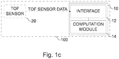
- Fig. 1c shows a block diagram of an embodiment of an (corresponding) apparatus 10 for determining distance information based on Time of Flight (ToF) sensor data.
- the apparatus 10 comprises an interface 12 for obtaining the ToF sensor data.
- the apparatus 10 comprises a computation module 14 that is coupled with the interface 12.
- the computation module 14 is configured to determine one or more saturated regions within the ToF sensor data.
- the computation module 14 is configured to determine distance information for one or more boundary regions located adjacent to the one or more saturated regions based on the ToF sensor data.
- the computation module 14 is configured to determine distance information for at least a part of the one or more saturated regions based on the distance information of the one or more boundary regions.
- Fig. 1c further shows a Time of Flight sensor module 100, e.g.
- a ToF camera 100 comprising the apparatus 10 and a ToF sensor 20.
- the computation module 14 may be configured to obtain the ToF sensor data from the ToF sensor 20 via the interface 12.
- the ToF sensor module 100 e.g. the apparatus 10 or the computation module 14 of the ToF sensor module may be configured to execute the method introduced in connection with Figs. 1a and 1b , e.g. in conjunction with the interface 12.
- the following description may relate to the method of Figs. 1a or 1b and/or to the apparatus 10 or Time of Flight sensor module 100 of Fig. 1c .
- distance information may comprise a distance measurement of the distance between a ToF sensor providing the ToF sensor data and one or more objects located in the vicinity of the ToF sensor data.
- the distance information may be represented by a distance image, a distance map or by a point cloud.
- the ToF sensor may provide the ToF sensor data using a two-dimensional grid of pixels.
- the ToF sensor data may be represented by a plurality of pixels, e.g. a plurality of pixels arranged in a two-dimensional grid.
- Pixels of the two-dimensional grid of pixels may each indicate an amplitude/intensity of the light incident to the pixel and distance of the measured object to the ToF sensor that is measured based on the incident light.
- the amplitude/distance image may be calculated by multiple phase measurements with different reference phases.
- the phase measurements may be an intermediate sensor output that is used to calculate the distance/intensity.
- the phase measurements may be used to determine, whether a pixel in the ToF sensor data is saturated.
- the distance information may represent or indicate the distance of the measured one or more objects to the ToF sensor.
- the distance information of the one or more saturated regions within the ToF sensor data may be replaced or supplanted by the determined distance information of at least a part of the one or more saturated regions.
- the method comprises obtaining 110 the ToF sensor data.
- the ToF sensor data may be obtained by reading out the ToF sensor data from a ToF sensor (e.g. a PMD imager) providing the ToF sensor data.
- the ToF sensor 20 is configured to provide the ToF sensor data.
- the ToF sensor data may comprise the amplitude and the distance information determined by the ToF sensor.
- the ToF sensor data may comprise the phase measurements of the ToF Sensor data.
- the ToF sensor data may comprise at least one phase measurement of light incident to the ToF sensor for each pixel of the ToF sensor data, and the method may determine the distance information and the amplitude/intensity information based on the at least one phase measurement of light incident to the ToF sensor.
- the phase measurements may be an intermediate sensor output of the ToF sensor during measurement process, which may be utilized to calculate the distance information and/or the intensity/amplitude information.
- the ToF sensor data may comprise the amplitude and the distance information determined by the ToF sensor, and an indication, whether a pixel of the ToF sensor data is saturated.
- the method further comprises determining 120 the one or more saturated regions within the ToF sensor data. If the ToF sensor data comprises information, whether a pixel within the ToF sensor data is saturated, the determining 120 of the one or more saturated regions may comprise detecting one or more continuous regions of saturated pixels within the ToF sensor data, and determining the one or more saturated regions based on the one or more continuous regions of saturated pixels. Otherwise, the method may additionally comprise determining which of the pixels are saturated.
- the method may (additionally) comprise determining, whether a pixel within the ToF sensor data is saturated.
- the amplitude/distance image is calculated by multiple phase-measurements with different reference phases. If a pixel is saturated in at least one of the phase-measurements, the amplitude/distance information of the pixel may be invalid. Saturated pixels of the single phase-measurement may be detected by checking whether the digitalized sensor readings are within the normal operating range. If the raw value of a pixel is outside of that range (e.g. close to the minimal or maximal limit), the pixel may be recognized as saturated and might not be used for valid amplitude/distance calculation.
- the ToF sensor data may comprise at least one phase measurement of light incident to a ToF sensor for each of the plurality of pixels of the ToF sensor data.
- the phase measurement may be determined relative to at least one reference signal.
- a pixel of the plurality of pixels may be determined 120 to belong to a saturated region of the one or more saturated regions if the phase measurement of the pixel is outside a range of valid phase measurements. This may enable the detection of saturated regions within the raw ToF sensor data.
- a pixel of the plurality of pixels may be determined 120 to belong to a saturated region of the one or more saturated regions if the phase measurement of the pixel is within a threshold of a maximal or minimal value of the phase measurement.
- the ToF sensor data comprises two or more phase measurements of light incident to a ToF sensor for each of the plurality of pixels.
- the two or more phase measurements may be determined relative to two or more reference signals.
- a pixel of the plurality of pixels may be determined to belong to a saturated region of the one or more saturated regions if at least one of the two or more phase measurements of the pixel is outside a range of valid phase measurements. This may increase a reliability of the determination.
- the method comprises identifying 130 the one or more boundary regions within the ToF sensor data.
- the one or more saturated regions may be caused by one or more objects.
- the one or more boundary regions may be based on stray light reflected off the one or more objects. In the ToF sensor data, the stray light may form a corona surrounding the one or more saturated regions. Consequently, the one or more boundary regions may be identified based to their proximity to the one or more saturated regions.
- the one or more boundary regions are identified 130 based on a proximity of the one or more boundary regions to the one or more saturated regions within the ToF sensor data, e.g. based on a proximity in pixel positions of the one or more boundary regions to the one or more saturated regions within the ToF sensor data. For example, pixels of the plurality of pixels that are located (directly) adjacent to a saturated pixel within the ToF sensor data (and are not themselves saturated) may be identified to belong to the one or more boundary regions. Another criterion is the amplitude (i.e. intensity) of the pixels.
- the ToF sensor data may be based on a sensing of light incident to a ToF sensor.
- the one or more boundary regions may be identified 130 based on an intensity of the sensed light of the one or more boundary regions within the ToF sensor data. For example, the one or more boundary regions may be identified 130 if an intensity of the sensed light of the one or more boundary regions is within an intensity range that is indicative of stray light. Alternatively or additionally, the one or more boundary regions may be identified 130 based on an intensity differential of the sensed light between the one or more boundary regions and adjacent regions within the ToF sensor data. For example, an intensity value of the sensed light within the adjacent regions, e.g. further regions within the ToF sensor data, that are not saturated or caused by stray light, may differ by more than 20% of the intensity value of the sensed light from an intensity value of pixels located within the adjacent regions.
- the extent of the one or more boundary regions may be arbitrarily set to a given number of pixel(s), such as 1 pixel, i.e. the pixels that are located directly adjacent to the one or more saturated regions may correspond to the one or more boundary regions. This may enable a simple determination of the one or more boundary regions, but may be susceptible to inaccuracies, which may be smoothed out if the extent of the one or more boundary regions is chosen to be wider. For example, as shown in Fig.
- an extent of the one or more boundary regions may be determined 132 based on a distance differential and/or based on an intensity differential between the one or more boundary regions and adjacent regions within the ToF sensor data. For example, if a distance of pixels that are located adjacent to pixels comprised in a boundary region of the one or more boundary regions, is different by at least a threshold value, e.g. by at least 10 cm, the extent of the one or more boundary region may be determined such, that the pixels that are located adjacent to the pixels comprised in the boundary region are excluded from the one or more boundary regions, e.g. in an iterative or recurrent fashion, starting from the pixels located directly adjacent to the one or more saturated regions.
- the intensity values of the pixels may be considered similarly.
- the extent of the one or more boundary region may be determined such, that the pixels that are located adjacent to the pixels comprised in the boundary region are excluded from the one or more boundary regions. This may enable the determination of the actual extent of the one or more boundary regions, and may thus enable a more precise determination of the distance information of the one or more boundary regions.
- the method further comprises determining 140 the distance information for the one or more boundary regions located adjacent to the one or more saturated regions based on the ToF sensor data.
- the determining 140 of the distance information or the one or more boundary regions may be based on the least one phase measurement of light incident to the ToF sensor for each pixel of the ToF sensor data comprised in the one or more boundary regions.
- the determining 140 of the distance information for the one or more boundary regions may comprise extracting the distance information of the one or more boundary regions from the ToF sensor data.
- the method comprises determining 150 distance information for at least a part of the one or more saturated regions based on the distance information of the one or more boundary regions.
- the determining 150 of the distance information for at least a part of the one or more saturated regions may correspond to an arbitrary attribution or estimation of the distance information for at least a part of the one or more saturated region.
- the distance information for at least a part of the one or more saturated regions may be determined (i.e. estimated or arbitrarily attributed) using an interpolation of the distance information of the one or more boundary regions.
- the one or more boundary regions may at least partially surround the one or more saturated regions.
- Distance information of pixels of a boundary region located at opposite ends of a saturated region that is at least partially surrounded by the boundary region may be used to interpolate (e.g. using bilinear interpolation) the distance information of at least part of the saturated region.
- the distance information for at least part of the one or more saturated regions may be determined 150 by interpolating the distance information for at least part of the one or more saturated regions based on the distance information of the one or more boundary regions, e.g. using bilinear interpolation. This may enable an estimation of the distance information for at least part of the one or more saturated regions.
- a bilinear interpolation may be used, based on two pairs of pixels located on opposite sides of a saturated region (i.e. pairwise opposite, such that straight lines that connect the pixels of the pairs in a two-dimensional representation of the ToF sensor data intersect at the pixel of the saturated region, for which the distance information is determined).
- the interpolation may be based on three-dimensional plane fitting of at least part of the one or more saturated regions based on the distance information of the one or more boundary regions. This may enable a more precise determination of the distance information of the one or more saturated regions.
- the method comprises discarding 160 the distance information of the one or more boundary regions.
- This may be desired as the distance information of the one or more boundary regions may originate from the stray light reflected off the objects that cause the one or more saturated regions, and might not reflect the actual distance at these regions of the ToF sensor data. Instead, the boundary regions may hold distance information for the adjacent saturated regions. They might not represent the distance for the containing pixel, but might hold the right distance values of the saturated regions at the wrong pixel position. At least some examples are based on using the out-of-place distance information to determine the distance information for the saturated regions.
- the points of the one or more boundary regions may be removed from the point cloud and/or the distance information of the pixels comprised by the one or more boundary regions within the ToF sensor data may be marked as invalid, e.g. by setting a confidence value of the pixels to zero.
- the interface 12 may correspond to one or more inputs and/or outputs for receiving and/or transmitting information, which may be in digital (bit) values according to a specified code, within a module, between modules or between modules of different entities.
- the computation module 14 may be implemented using one or more processing units or computation units, one or more processing devices or computation devices, any means for computing, such as a processor, a computer or a programmable hardware component being operable with accordingly adapted software.
- the described function of the computation module 14 may as well be implemented in software, which is then executed on one or more programmable hardware components.
- Such hardware components may comprise a general purpose processor, a Digital Signal Processor (DSP), a micro-controller, etc.
- the Time of Flight sensor 20 may comprise at least one pixel element, e.g. a photonic mixing device (PMD) or be at least part of an image sensor circuit, for example, and may include a pixel sensor array, e.g. an array of pixel elements, for example. Each pixel element of the pixel array may be configured to receive reflected modulated light, which may be emitted by a time of flight light source and reflected by an object, for example.
- the ToF sensor 20 may be configured to provide the ToF sensor data comprising the plurality of pixels based on phase measurements obtained by the array of pixel elements.
- the ToF sensor module may further comprise a ToF light source configured to provide the modulated light.
- the method and/or apparatus may comprise one or more additional optional features corresponding to one or more aspects of the proposed concept or one or more examples described above or below.
- At least some embodiments relate to an approximation of saturated areas in time-of-flight images.
- Saturated pixels in ToF images may cause invalid distance values.
- applications e.g. object detection
- invalid areas in the distance image may cause these applications to fail.
- Saturated pixels are invalid pixels and are often discarded.
- a saturated pixel state may be detected and the corresponding distance values can be marked as invalid.
- These holes in the distance image may cause problems since they cannot be directly assigned with a distance value.
- the distance of the area in the hole might be completely unknown and thus may correspond to problems in certain applications.
- These holes might also occur with highly reflective or close objects at the lowest possible exposure time of a ToF sensor, e.g. with retroreflectors in signs, street signs, objects, that are too close, or glasses for face recognition.
- saturated pixels are often caused by too much light arriving at the sensor, a significant amount of stray-light may occur around the object reflecting a lot of light. This stray-light may enable valid distance measurements of the saturated area.
- Figs. 2a to 2c show schematic illustrations of measurements taken in an experimental setup.
- the exemplary experimental setup is laid out.
- a uniform reflective surface 200 e.g. a piece of white cardboard
- the piece of cardboard is arranged too close (for the used exposure time) to a ToF camera that is used to determine distance information of the room with the piece of cardboard.
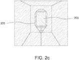
- Figs. 2b and 2c show schematic representations of the amplitude image and distance image (e.g. of the ToF sensor data) that is recorded of the setup by a ToF sensor.
- the piece of cardboard causes a saturated region within the ToS sensor data.
- a corona (scattered light) 220 is visible around the piece of cardboard 200.
- the distance image shown in Fig. 2c comprises no valid distance information for the piece of cardboard.
- a small corona 210 is also visible around the piece of cardboard.
- the amplitude of the piece of cardboard was markedly higher than that of the rest of the room, with the boundary region 210 surrounding the piece of cardboard being slightly lower (but still markedly higher than that of the rest of the room).
- Fig. 3 shows an excerpt of a point cloud of a measurement taken in a further experimental setup.
- an X-shaped reflector is attached to a box and positioned some way from the ToF sensor.
- the region of the ToF sensor data representing the X-shaped reflector is saturated, while the remainder of the box is barely visible.
- the stray light reflected off the X-shaped reflector yields distance information, which may be used to determine the distance information of the saturated region corresponding to the X-shaped reflector.
- At least some embodiments may replace the invalid pixel area (e.g. the piece of cardboard in the above example, or, more general, the one or more saturated regions) with the interpolated distance values from the surrounding stray-light.
- Embodiments may replace the saturated pixel with the surrounding valid depth data.
- the saturated area may be interpolated by 3D Plane Fitting using the surrounding stray light pixels as basis.
- Especially small objects may be replaced by the interpolation of the corresponding stray-light.
- Examples may further be or relate to a computer program having a program code for performing one or more of the above methods, when the computer program is executed on a computer or processor. Steps, operations or processes of various above-described methods may be performed by programmed computers or processors. Examples may also cover program storage devices such as digital data storage media, which are machine, processor or computer readable and encode machine-executable, processor-executable or computer-executable programs of instructions. The instructions perform or cause performing some or all of the acts of the above-described methods.
- the program storage devices may comprise or be, for instance, digital memories, magnetic storage media such as magnetic disks and magnetic tapes, hard drives, or optically readable digital data storage media.
- FIG. 1 may also cover computers, processors or control units programmed to perform the acts of the above-described methods or (field) programmable logic arrays ((F)PLAs) or (field) programmable gate arrays ((F)PGAs), programmed to perform the acts of the above-described methods.
- a functional block denoted as "means for " performing a certain function may refer to a circuit that is configured to perform a certain function.
- a "means for s.th.” may be implemented as a "means configured to or suited for s.th.”, such as a device or a circuit configured to or suited for the respective task.
- Functions of various elements shown in the figures may be implemented in the form of dedicated hardware, such as “a signal provider”, “a signal processing unit”, “a processor”, “a controller”, etc. as well as hardware capable of executing software in association with appropriate software.
- a processor the functions may be provided by a single dedicated processor, by a single shared processor, or by a plurality of individual processors, some of which or all of which may be shared.
- processor or “controller” is by far not limited to hardware exclusively capable of executing software, but may include digital signal processor (DSP) hardware, network processor, application specific integrated circuit (ASIC), field programmable gate array (FPGA), read only memory (ROM) for storing software, random access memory (RAM), and nonvolatile storage.
- DSP digital signal processor
- ASIC application specific integrated circuit
- FPGA field programmable gate array
- ROM read only memory
- RAM random access memory
- nonvolatile storage Other hardware, conventional and/or custom, may also be included.
- a block diagram may, for instance, illustrate a high-level circuit diagram implementing the principles of the disclosure.
- a flow chart, a flow diagram, a state transition diagram, a pseudo code, and the like may represent various processes, operations or steps, which may, for instance, be substantially represented in computer readable medium and so executed by a computer or processor, whether or not such computer or processor is explicitly shown.
- Methods disclosed in the specification or in the claims may be implemented by a device having means for performing each of the respective acts of these methods.
- each claim may stand on its own as a separate example. While each claim may stand on its own as a separate example, it is to be noted that - although a dependent claim may refer in the claims to a specific combination with one or more other claims - other examples may also include a combination of the dependent claim with the subject matter of each other dependent or independent claim. Such combinations are explicitly proposed herein unless it is stated that a specific combination is not intended. Furthermore, it is intended to include also features of a claim to any other independent claim even if this claim is not directly made dependent to the independent claim.
Landscapes
- Engineering & Computer Science (AREA)
- Physics & Mathematics (AREA)
- Computer Networks & Wireless Communication (AREA)
- General Physics & Mathematics (AREA)
- Radar, Positioning & Navigation (AREA)
- Remote Sensing (AREA)
- Electromagnetism (AREA)
- Multimedia (AREA)
- Signal Processing (AREA)
- Optical Radar Systems And Details Thereof (AREA)
- Measurement Of Optical Distance (AREA)
Priority Applications (3)
| Application Number | Priority Date | Filing Date | Title |
|---|---|---|---|
| EP18211157.5A EP3663801B1 (de) | 2018-12-07 | 2018-12-07 | Flugzeitsensormodul, verfahren, vorrichtung und computerprogramm zur bestimmung von entfernungsdaten auf basis von flugzeitsensordaten |
| US16/705,832 US11879993B2 (en) | 2018-12-07 | 2019-12-06 | Time of flight sensor module, method, apparatus and computer program for determining distance information based on time of flight sensor data |
| CN201911250861.4A CN111289988B (zh) | 2018-12-07 | 2019-12-09 | 用于确定距离信息的方法、装置以及计算机程序 |
Applications Claiming Priority (1)
| Application Number | Priority Date | Filing Date | Title |
|---|---|---|---|
| EP18211157.5A EP3663801B1 (de) | 2018-12-07 | 2018-12-07 | Flugzeitsensormodul, verfahren, vorrichtung und computerprogramm zur bestimmung von entfernungsdaten auf basis von flugzeitsensordaten |
Publications (2)
| Publication Number | Publication Date |
|---|---|
| EP3663801A1 true EP3663801A1 (de) | 2020-06-10 |
| EP3663801B1 EP3663801B1 (de) | 2022-09-28 |
Family
ID=64661237
Family Applications (1)
| Application Number | Title | Priority Date | Filing Date |
|---|---|---|---|
| EP18211157.5A Active EP3663801B1 (de) | 2018-12-07 | 2018-12-07 | Flugzeitsensormodul, verfahren, vorrichtung und computerprogramm zur bestimmung von entfernungsdaten auf basis von flugzeitsensordaten |
Country Status (3)
| Country | Link |
|---|---|
| US (1) | US11879993B2 (de) |
| EP (1) | EP3663801B1 (de) |
| CN (1) | CN111289988B (de) |
Families Citing this family (6)
| Publication number | Priority date | Publication date | Assignee | Title |
|---|---|---|---|---|
| WO2021118588A1 (en) * | 2019-12-13 | 2021-06-17 | Hewlett-Packard Development Company, L.P. | Object tracking |
| DE102022115273A1 (de) * | 2022-06-20 | 2023-12-21 | Valeo Detection Systems GmbH | Verfahren zum Betreiben eines LiDAR-Systems, LiDAR-System und Fahrzeug aufweisend wenigstens ein LiDAR-System |
| DE102022115275A1 (de) * | 2022-06-20 | 2023-12-21 | Valeo Detection Systems GmbH | Verfahren zum Betreiben eines LiDAR-Systems, LiDAR-System und Fahrzeug mit wenigstens einem LiDAR-System |
| CN120958342A (zh) * | 2023-03-29 | 2025-11-14 | 索尼集团公司 | 控制装置、距离测量装置和控制方法 |
| US20240353562A1 (en) * | 2023-04-18 | 2024-10-24 | Stmicroelectronics International N.V. | Reduced resolution time-of-flight shape recognition |
| DE102023135584A1 (de) * | 2023-12-18 | 2025-06-18 | Valeo Schalter Und Sensoren Gmbh | Verfahren zum Betreiben eines iToF-LiDAR-Systems, bei dem auf Basis von validierten Empfangsgrößen korrigierte Empfangsgrößen ermittelt werden, iToF-LiDAR-System, Fahrerassistenzsystem und Fahrzeug |
Citations (3)
| Publication number | Priority date | Publication date | Assignee | Title |
|---|---|---|---|---|
| US6753876B2 (en) * | 2001-12-21 | 2004-06-22 | General Electric Company | Method for high dynamic range image construction based on multiple images with multiple illumination intensities |
| WO2017183114A1 (ja) * | 2016-04-19 | 2017-10-26 | 株式会社日立エルジーデータストレージ | 距離画像生成装置および距離画像生成方法 |
| WO2018222120A1 (en) * | 2017-05-30 | 2018-12-06 | Photon Sports Technologies Ab | Method and camera arrangement for measuring a movement of a person |
Family Cites Families (20)
| Publication number | Priority date | Publication date | Assignee | Title |
|---|---|---|---|---|
| US20070024721A1 (en) | 2005-07-29 | 2007-02-01 | Rogers Sean S | Compensating for improperly exposed areas in digital images |
| JP5123137B2 (ja) * | 2008-01-22 | 2013-01-16 | 株式会社リコー | 撮像装置および撮像方法 |
| EP2116864A1 (de) | 2008-05-09 | 2009-11-11 | Vrije Universiteit Brussel | Entfernungsmessung mittels Laufzeitmessung mit Unterdrückung von Hintergrundstrahlung |
| JP5448617B2 (ja) * | 2008-08-19 | 2014-03-19 | パナソニック株式会社 | 距離推定装置、距離推定方法、プログラム、集積回路およびカメラ |
| US8964028B2 (en) * | 2009-12-21 | 2015-02-24 | Mesa Imaging Ag | Stray light compensation method and system for time of flight camera systems |
| JP5804467B2 (ja) | 2010-03-31 | 2015-11-04 | 北陽電機株式会社 | 信号処理装置、及び走査式測距装置 |
| AT513589B1 (de) | 2012-11-08 | 2015-11-15 | Bluetechnix Gmbh | Aufnahmeverfahren für zumindest zwei ToF-Kameras |
| KR101904720B1 (ko) * | 2012-12-28 | 2018-10-05 | 삼성전자주식회사 | 영상 처리 장치 및 방법 |
| WO2014177750A1 (en) * | 2013-04-29 | 2014-11-06 | Nokia Corporation | A method and apparatus for fusing distance data from a distance sensing camera with an image |
| US9613406B2 (en) * | 2015-03-31 | 2017-04-04 | Nokia Technologies Oy | Method and apparatus for providing specular surface reconstruction |
| LU92688B1 (en) | 2015-04-01 | 2016-10-03 | Iee Int Electronics & Eng Sa | Method and system for real-time motion artifact handling and noise removal for tof sensor images |
| CN107710015B (zh) * | 2015-07-03 | 2021-08-24 | 新唐科技日本株式会社 | 距离测量装置以及距离图像合成方法 |
| EP3165874B1 (de) | 2015-11-04 | 2020-08-19 | Hexagon Technology Center GmbH | Verfahren und vorrichtung für triangulationsbasierte abstandsmessung |
| US10557925B2 (en) | 2016-08-26 | 2020-02-11 | Samsung Electronics Co., Ltd. | Time-of-flight (TOF) image sensor using amplitude modulation for range measurement |
| US11448757B2 (en) | 2016-11-29 | 2022-09-20 | Nuvoton Technology Corporation Japan | Distance measuring device |
| US10242454B2 (en) | 2017-01-25 | 2019-03-26 | Google Llc | System for depth data filtering based on amplitude energy values |
| US11113845B2 (en) * | 2017-09-18 | 2021-09-07 | Apple Inc. | Point cloud compression using non-cubic projections and masks |
| JP2019086365A (ja) * | 2017-11-06 | 2019-06-06 | 株式会社日立製作所 | 位置推定システム |
| CN108445500A (zh) | 2018-02-07 | 2018-08-24 | 余晓智 | 一种tof传感器的距离计算方法及系统 |
| JP7139168B2 (ja) * | 2018-07-04 | 2022-09-20 | 株式会社日立エルジーデータストレージ | 距離測定装置 |
-
2018
- 2018-12-07 EP EP18211157.5A patent/EP3663801B1/de active Active
-
2019
- 2019-12-06 US US16/705,832 patent/US11879993B2/en active Active
- 2019-12-09 CN CN201911250861.4A patent/CN111289988B/zh active Active
Patent Citations (4)
| Publication number | Priority date | Publication date | Assignee | Title |
|---|---|---|---|---|
| US6753876B2 (en) * | 2001-12-21 | 2004-06-22 | General Electric Company | Method for high dynamic range image construction based on multiple images with multiple illumination intensities |
| WO2017183114A1 (ja) * | 2016-04-19 | 2017-10-26 | 株式会社日立エルジーデータストレージ | 距離画像生成装置および距離画像生成方法 |
| US20190129034A1 (en) * | 2016-04-19 | 2019-05-02 | Hitachi-Lg Data Storage, Inc. | Range image generation apparatus and range image generation method |
| WO2018222120A1 (en) * | 2017-05-30 | 2018-12-06 | Photon Sports Technologies Ab | Method and camera arrangement for measuring a movement of a person |
Also Published As
| Publication number | Publication date |
|---|---|
| EP3663801B1 (de) | 2022-09-28 |
| CN111289988B (zh) | 2024-02-02 |
| CN111289988A (zh) | 2020-06-16 |
| US20200182971A1 (en) | 2020-06-11 |
| US11879993B2 (en) | 2024-01-23 |
Similar Documents
| Publication | Publication Date | Title |
|---|---|---|
| US11879993B2 (en) | Time of flight sensor module, method, apparatus and computer program for determining distance information based on time of flight sensor data | |
| US10430956B2 (en) | Time-of-flight (TOF) capturing apparatus and image processing method of reducing distortion of depth caused by multiple reflection | |
| US9424650B2 (en) | Sensor fusion for depth estimation | |
| US10914817B2 (en) | Multipath interference error correction in a time of flight sensor | |
| JP6239594B2 (ja) | 3d情報処理装置及び方法 | |
| CN106851238B (zh) | 白平衡控制方法、白平衡控制装置及电子装置 | |
| US20110310376A1 (en) | Apparatus and method to correct image | |
| US20190147624A1 (en) | Method for Processing a Raw Image of a Time-of-Flight Camera, Image Processing Apparatus and Computer Program | |
| US20200280691A1 (en) | Vision Sensor, a Method of Vision Sensing, and a Depth Sensor Assembly | |
| CN111684304B (zh) | 距离飞行时间模组 | |
| Belhedi et al. | Noise modelling in time‐of‐flight sensors with application to depth noise removal and uncertainty estimation in three‐dimensional measurement | |
| WO2016206004A1 (zh) | 一种获取深度信息的拍照设备和方法 | |
| US9906717B1 (en) | Method for generating a high-resolution depth image and an apparatus for generating a high-resolution depth image | |
| US20140184746A1 (en) | Image processing method and apparauts | |
| Rauscher et al. | A comparison of 3d sensors for wheeled mobile robots | |
| Chen et al. | 3D reconstruction from IR thermal images and reprojective evaluations | |
| Leo et al. | Robust estimation of object dimensions and external defect detection with a low-cost sensor | |
| Song et al. | Estimation of kinect depth confidence through self-training | |
| CN113014899B (zh) | 一种双目图像的视差确定方法、装置及系统 | |
| Stommel et al. | Inpainting of missing values in the Kinect sensor's depth maps based on background estimates | |
| EP3688407B1 (de) | Lichtprojektionssysteme | |
| CN110018483A (zh) | 物体距离估算方法与电子装置 | |
| US11972512B2 (en) | Directional editing of digital images | |
| Xiao et al. | A new three-dimensional laser scanner design and its performance analysis | |
| Langmann | Wide area 2D/3D imaging: development, analysis and applications |
Legal Events
| Date | Code | Title | Description |
|---|---|---|---|
| PUAI | Public reference made under article 153(3) epc to a published international application that has entered the european phase |
Free format text: ORIGINAL CODE: 0009012 |
|
| STAA | Information on the status of an ep patent application or granted ep patent |
Free format text: STATUS: THE APPLICATION HAS BEEN PUBLISHED |
|
| AK | Designated contracting states |
Kind code of ref document: A1 Designated state(s): AL AT BE BG CH CY CZ DE DK EE ES FI FR GB GR HR HU IE IS IT LI LT LU LV MC MK MT NL NO PL PT RO RS SE SI SK SM TR |
|
| AX | Request for extension of the european patent |
Extension state: BA ME |
|
| STAA | Information on the status of an ep patent application or granted ep patent |
Free format text: STATUS: REQUEST FOR EXAMINATION WAS MADE |
|
| 17P | Request for examination filed |
Effective date: 20201015 |
|
| RBV | Designated contracting states (corrected) |
Designated state(s): AL AT BE BG CH CY CZ DE DK EE ES FI FR GB GR HR HU IE IS IT LI LT LU LV MC MK MT NL NO PL PT RO RS SE SI SK SM TR |
|
| GRAP | Despatch of communication of intention to grant a patent |
Free format text: ORIGINAL CODE: EPIDOSNIGR1 |
|
| STAA | Information on the status of an ep patent application or granted ep patent |
Free format text: STATUS: GRANT OF PATENT IS INTENDED |
|
| INTG | Intention to grant announced |
Effective date: 20220509 |
|
| GRAS | Grant fee paid |
Free format text: ORIGINAL CODE: EPIDOSNIGR3 |
|
| GRAA | (expected) grant |
Free format text: ORIGINAL CODE: 0009210 |
|
| STAA | Information on the status of an ep patent application or granted ep patent |
Free format text: STATUS: THE PATENT HAS BEEN GRANTED |
|
| AK | Designated contracting states |
Kind code of ref document: B1 Designated state(s): AL AT BE BG CH CY CZ DE DK EE ES FI FR GB GR HR HU IE IS IT LI LT LU LV MC MK MT NL NO PL PT RO RS SE SI SK SM TR |
|
| REG | Reference to a national code |
Ref country code: GB Ref legal event code: FG4D |
|
| REG | Reference to a national code |
Ref country code: CH Ref legal event code: EP |
|
| REG | Reference to a national code |
Ref country code: DE Ref legal event code: R096 Ref document number: 602018041074 Country of ref document: DE |
|
| REG | Reference to a national code |
Ref country code: AT Ref legal event code: REF Ref document number: 1521595 Country of ref document: AT Kind code of ref document: T Effective date: 20221015 |
|
| REG | Reference to a national code |
Ref country code: IE Ref legal event code: FG4D |
|
| REG | Reference to a national code |
Ref country code: LT Ref legal event code: MG9D |
|
| PG25 | Lapsed in a contracting state [announced via postgrant information from national office to epo] |
Ref country code: SE Free format text: LAPSE BECAUSE OF FAILURE TO SUBMIT A TRANSLATION OF THE DESCRIPTION OR TO PAY THE FEE WITHIN THE PRESCRIBED TIME-LIMIT Effective date: 20220928 Ref country code: RS Free format text: LAPSE BECAUSE OF FAILURE TO SUBMIT A TRANSLATION OF THE DESCRIPTION OR TO PAY THE FEE WITHIN THE PRESCRIBED TIME-LIMIT Effective date: 20220928 Ref country code: NO Free format text: LAPSE BECAUSE OF FAILURE TO SUBMIT A TRANSLATION OF THE DESCRIPTION OR TO PAY THE FEE WITHIN THE PRESCRIBED TIME-LIMIT Effective date: 20221228 Ref country code: LV Free format text: LAPSE BECAUSE OF FAILURE TO SUBMIT A TRANSLATION OF THE DESCRIPTION OR TO PAY THE FEE WITHIN THE PRESCRIBED TIME-LIMIT Effective date: 20220928 Ref country code: LT Free format text: LAPSE BECAUSE OF FAILURE TO SUBMIT A TRANSLATION OF THE DESCRIPTION OR TO PAY THE FEE WITHIN THE PRESCRIBED TIME-LIMIT Effective date: 20220928 Ref country code: FI Free format text: LAPSE BECAUSE OF FAILURE TO SUBMIT A TRANSLATION OF THE DESCRIPTION OR TO PAY THE FEE WITHIN THE PRESCRIBED TIME-LIMIT Effective date: 20220928 |
|
| REG | Reference to a national code |
Ref country code: NL Ref legal event code: MP Effective date: 20220928 |
|
| REG | Reference to a national code |
Ref country code: AT Ref legal event code: MK05 Ref document number: 1521595 Country of ref document: AT Kind code of ref document: T Effective date: 20220928 |
|
| PG25 | Lapsed in a contracting state [announced via postgrant information from national office to epo] |
Ref country code: HR Free format text: LAPSE BECAUSE OF FAILURE TO SUBMIT A TRANSLATION OF THE DESCRIPTION OR TO PAY THE FEE WITHIN THE PRESCRIBED TIME-LIMIT Effective date: 20220928 Ref country code: GR Free format text: LAPSE BECAUSE OF FAILURE TO SUBMIT A TRANSLATION OF THE DESCRIPTION OR TO PAY THE FEE WITHIN THE PRESCRIBED TIME-LIMIT Effective date: 20221229 |
|
| PG25 | Lapsed in a contracting state [announced via postgrant information from national office to epo] |
Ref country code: SM Free format text: LAPSE BECAUSE OF FAILURE TO SUBMIT A TRANSLATION OF THE DESCRIPTION OR TO PAY THE FEE WITHIN THE PRESCRIBED TIME-LIMIT Effective date: 20220928 Ref country code: RO Free format text: LAPSE BECAUSE OF FAILURE TO SUBMIT A TRANSLATION OF THE DESCRIPTION OR TO PAY THE FEE WITHIN THE PRESCRIBED TIME-LIMIT Effective date: 20220928 Ref country code: PT Free format text: LAPSE BECAUSE OF FAILURE TO SUBMIT A TRANSLATION OF THE DESCRIPTION OR TO PAY THE FEE WITHIN THE PRESCRIBED TIME-LIMIT Effective date: 20230130 Ref country code: ES Free format text: LAPSE BECAUSE OF FAILURE TO SUBMIT A TRANSLATION OF THE DESCRIPTION OR TO PAY THE FEE WITHIN THE PRESCRIBED TIME-LIMIT Effective date: 20220928 Ref country code: CZ Free format text: LAPSE BECAUSE OF FAILURE TO SUBMIT A TRANSLATION OF THE DESCRIPTION OR TO PAY THE FEE WITHIN THE PRESCRIBED TIME-LIMIT Effective date: 20220928 Ref country code: AT Free format text: LAPSE BECAUSE OF FAILURE TO SUBMIT A TRANSLATION OF THE DESCRIPTION OR TO PAY THE FEE WITHIN THE PRESCRIBED TIME-LIMIT Effective date: 20220928 |
|
| PG25 | Lapsed in a contracting state [announced via postgrant information from national office to epo] |
Ref country code: SK Free format text: LAPSE BECAUSE OF FAILURE TO SUBMIT A TRANSLATION OF THE DESCRIPTION OR TO PAY THE FEE WITHIN THE PRESCRIBED TIME-LIMIT Effective date: 20220928 Ref country code: PL Free format text: LAPSE BECAUSE OF FAILURE TO SUBMIT A TRANSLATION OF THE DESCRIPTION OR TO PAY THE FEE WITHIN THE PRESCRIBED TIME-LIMIT Effective date: 20220928 Ref country code: IS Free format text: LAPSE BECAUSE OF FAILURE TO SUBMIT A TRANSLATION OF THE DESCRIPTION OR TO PAY THE FEE WITHIN THE PRESCRIBED TIME-LIMIT Effective date: 20230128 Ref country code: EE Free format text: LAPSE BECAUSE OF FAILURE TO SUBMIT A TRANSLATION OF THE DESCRIPTION OR TO PAY THE FEE WITHIN THE PRESCRIBED TIME-LIMIT Effective date: 20220928 |
|
| REG | Reference to a national code |
Ref country code: DE Ref legal event code: R097 Ref document number: 602018041074 Country of ref document: DE |
|
| PG25 | Lapsed in a contracting state [announced via postgrant information from national office to epo] |
Ref country code: NL Free format text: LAPSE BECAUSE OF FAILURE TO SUBMIT A TRANSLATION OF THE DESCRIPTION OR TO PAY THE FEE WITHIN THE PRESCRIBED TIME-LIMIT Effective date: 20220928 Ref country code: AL Free format text: LAPSE BECAUSE OF FAILURE TO SUBMIT A TRANSLATION OF THE DESCRIPTION OR TO PAY THE FEE WITHIN THE PRESCRIBED TIME-LIMIT Effective date: 20220928 |
|
| P01 | Opt-out of the competence of the unified patent court (upc) registered |
Effective date: 20230528 |
|
| PG25 | Lapsed in a contracting state [announced via postgrant information from national office to epo] |
Ref country code: DK Free format text: LAPSE BECAUSE OF FAILURE TO SUBMIT A TRANSLATION OF THE DESCRIPTION OR TO PAY THE FEE WITHIN THE PRESCRIBED TIME-LIMIT Effective date: 20220928 |
|
| REG | Reference to a national code |
Ref country code: CH Ref legal event code: PL |
|
| PLBE | No opposition filed within time limit |
Free format text: ORIGINAL CODE: 0009261 |
|
| STAA | Information on the status of an ep patent application or granted ep patent |
Free format text: STATUS: NO OPPOSITION FILED WITHIN TIME LIMIT |
|
| REG | Reference to a national code |
Ref country code: BE Ref legal event code: MM Effective date: 20221231 |
|
| PG25 | Lapsed in a contracting state [announced via postgrant information from national office to epo] |
Ref country code: LU Free format text: LAPSE BECAUSE OF NON-PAYMENT OF DUE FEES Effective date: 20221207 |
|
| 26N | No opposition filed |
Effective date: 20230629 |
|
| PG25 | Lapsed in a contracting state [announced via postgrant information from national office to epo] |
Ref country code: LI Free format text: LAPSE BECAUSE OF NON-PAYMENT OF DUE FEES Effective date: 20221231 Ref country code: IE Free format text: LAPSE BECAUSE OF NON-PAYMENT OF DUE FEES Effective date: 20221207 Ref country code: CH Free format text: LAPSE BECAUSE OF NON-PAYMENT OF DUE FEES Effective date: 20221231 |
|
| PG25 | Lapsed in a contracting state [announced via postgrant information from national office to epo] |
Ref country code: SI Free format text: LAPSE BECAUSE OF FAILURE TO SUBMIT A TRANSLATION OF THE DESCRIPTION OR TO PAY THE FEE WITHIN THE PRESCRIBED TIME-LIMIT Effective date: 20220928 Ref country code: BE Free format text: LAPSE BECAUSE OF NON-PAYMENT OF DUE FEES Effective date: 20221231 |
|
| PG25 | Lapsed in a contracting state [announced via postgrant information from national office to epo] |
Ref country code: HU Free format text: LAPSE BECAUSE OF FAILURE TO SUBMIT A TRANSLATION OF THE DESCRIPTION OR TO PAY THE FEE WITHIN THE PRESCRIBED TIME-LIMIT; INVALID AB INITIO Effective date: 20181207 |
|
| PG25 | Lapsed in a contracting state [announced via postgrant information from national office to epo] |
Ref country code: CY Free format text: LAPSE BECAUSE OF FAILURE TO SUBMIT A TRANSLATION OF THE DESCRIPTION OR TO PAY THE FEE WITHIN THE PRESCRIBED TIME-LIMIT Effective date: 20220928 |
|
| PG25 | Lapsed in a contracting state [announced via postgrant information from national office to epo] |
Ref country code: MK Free format text: LAPSE BECAUSE OF FAILURE TO SUBMIT A TRANSLATION OF THE DESCRIPTION OR TO PAY THE FEE WITHIN THE PRESCRIBED TIME-LIMIT Effective date: 20220928 Ref country code: IT Free format text: LAPSE BECAUSE OF FAILURE TO SUBMIT A TRANSLATION OF THE DESCRIPTION OR TO PAY THE FEE WITHIN THE PRESCRIBED TIME-LIMIT Effective date: 20220928 |
|
| PG25 | Lapsed in a contracting state [announced via postgrant information from national office to epo] |
Ref country code: MC Free format text: LAPSE BECAUSE OF FAILURE TO SUBMIT A TRANSLATION OF THE DESCRIPTION OR TO PAY THE FEE WITHIN THE PRESCRIBED TIME-LIMIT Effective date: 20220928 |
|
| PG25 | Lapsed in a contracting state [announced via postgrant information from national office to epo] |
Ref country code: TR Free format text: LAPSE BECAUSE OF FAILURE TO SUBMIT A TRANSLATION OF THE DESCRIPTION OR TO PAY THE FEE WITHIN THE PRESCRIBED TIME-LIMIT Effective date: 20220928 Ref country code: MC Free format text: LAPSE BECAUSE OF FAILURE TO SUBMIT A TRANSLATION OF THE DESCRIPTION OR TO PAY THE FEE WITHIN THE PRESCRIBED TIME-LIMIT Effective date: 20220928 |
|
| PG25 | Lapsed in a contracting state [announced via postgrant information from national office to epo] |
Ref country code: BG Free format text: LAPSE BECAUSE OF FAILURE TO SUBMIT A TRANSLATION OF THE DESCRIPTION OR TO PAY THE FEE WITHIN THE PRESCRIBED TIME-LIMIT Effective date: 20220928 |
|
| PG25 | Lapsed in a contracting state [announced via postgrant information from national office to epo] |
Ref country code: MT Free format text: LAPSE BECAUSE OF FAILURE TO SUBMIT A TRANSLATION OF THE DESCRIPTION OR TO PAY THE FEE WITHIN THE PRESCRIBED TIME-LIMIT Effective date: 20220928 |
|
| PGFP | Annual fee paid to national office [announced via postgrant information from national office to epo] |
Ref country code: GB Payment date: 20251219 Year of fee payment: 8 |
|
| PGFP | Annual fee paid to national office [announced via postgrant information from national office to epo] |
Ref country code: FR Payment date: 20251229 Year of fee payment: 8 |
|
| PGFP | Annual fee paid to national office [announced via postgrant information from national office to epo] |
Ref country code: DE Payment date: 20260224 Year of fee payment: 8 |