EP3663695B1 - Konstitutiver sammelbehälter für einen wärmetauscher - Google Patents
Konstitutiver sammelbehälter für einen wärmetauscher Download PDFInfo
- Publication number
- EP3663695B1 EP3663695B1 EP18210197.2A EP18210197A EP3663695B1 EP 3663695 B1 EP3663695 B1 EP 3663695B1 EP 18210197 A EP18210197 A EP 18210197A EP 3663695 B1 EP3663695 B1 EP 3663695B1
- Authority
- EP
- European Patent Office
- Prior art keywords
- header
- cavity
- partition
- projection
- cover
- Prior art date
- Legal status (The legal status is an assumption and is not a legal conclusion. Google has not performed a legal analysis and makes no representation as to the accuracy of the status listed.)
- Active
Links
- 238000005192 partition Methods 0.000 claims description 71
- 238000000034 method Methods 0.000 claims description 6
- 239000003507 refrigerant Substances 0.000 description 18
- 239000012530 fluid Substances 0.000 description 10
- 230000015572 biosynthetic process Effects 0.000 description 8
- 239000000463 material Substances 0.000 description 8
- 238000003780 insertion Methods 0.000 description 4
- 230000037431 insertion Effects 0.000 description 4
- 241001080024 Telles Species 0.000 description 3
- 230000004087 circulation Effects 0.000 description 3
- 239000002826 coolant Substances 0.000 description 3
- 238000005219 brazing Methods 0.000 description 2
- 238000004891 communication Methods 0.000 description 2
- 230000006854 communication Effects 0.000 description 2
- 230000006378 damage Effects 0.000 description 2
- 230000002093 peripheral effect Effects 0.000 description 2
- 238000007789 sealing Methods 0.000 description 2
- 238000012546 transfer Methods 0.000 description 2
- 238000007514 turning Methods 0.000 description 2
- 241000897276 Termes Species 0.000 description 1
- 240000008042 Zea mays Species 0.000 description 1
- 230000004308 accommodation Effects 0.000 description 1
- 239000011324 bead Substances 0.000 description 1
- 230000009850 completed effect Effects 0.000 description 1
- 238000006073 displacement reaction Methods 0.000 description 1
- 239000000945 filler Substances 0.000 description 1
- 238000009434 installation Methods 0.000 description 1
- 238000004519 manufacturing process Methods 0.000 description 1
- 230000000051 modifying effect Effects 0.000 description 1
- 238000011017 operating method Methods 0.000 description 1
- 230000036961 partial effect Effects 0.000 description 1
- 230000008569 process Effects 0.000 description 1
- 238000004080 punching Methods 0.000 description 1
Images


Classifications
-
- F—MECHANICAL ENGINEERING; LIGHTING; HEATING; WEAPONS; BLASTING
- F28—HEAT EXCHANGE IN GENERAL
- F28F—DETAILS OF HEAT-EXCHANGE AND HEAT-TRANSFER APPARATUS, OF GENERAL APPLICATION
- F28F9/00—Casings; Header boxes; Auxiliary supports for elements; Auxiliary members within casings
- F28F9/02—Header boxes; End plates
- F28F9/0202—Header boxes having their inner space divided by partitions
- F28F9/0204—Header boxes having their inner space divided by partitions for elongated header box, e.g. with transversal and longitudinal partitions
- F28F9/0209—Header boxes having their inner space divided by partitions for elongated header box, e.g. with transversal and longitudinal partitions having only transversal partitions
- F28F9/0212—Header boxes having their inner space divided by partitions for elongated header box, e.g. with transversal and longitudinal partitions having only transversal partitions the partitions being separate elements attached to header boxes
Definitions
- the present invention relates to a manifold constituting a heat exchanger. Its object is such a collector as well as a heat exchanger comprising such a collector.
- a motor vehicle is currently equipped with a refrigerant fluid circuit for modifying a temperature of the air contained inside a passenger compartment of the motor vehicle.
- the refrigerant circuit comprises at least one heat exchanger, such as a condenser, a gas cooler or an evaporator, which is arranged to allow a transfer of calories between the refrigerant circulating inside the heat exchanger. heat and a flow of air passing through it.
- the heat exchanger comprises a plurality of tubes which are designed to be traversed by the air flow and which are interposed between two manifolds, including for example an inlet manifold for the refrigerant fluid inside the heat exchanger. heat and a coolant outlet manifold outside the heat exchanger, according to an exemplary embodiment of such a heat exchanger.
- heat exchangers which are similar to the preamble of claim 1.
- document [ EP0798530 A1 ] shows a heat exchanger having a reservoir (6) formed of at least a first and a second reservoir elements interconnected and at least one partition disposed in the reservoir to divide the interior of the reservoir into at least two chambers.
- a pair of protrusions extending in a circumferential direction of the interior surface of the reservoir and disposed in an axial direction of the reservoir are provided on the interior surface of the first reservoir member to hold an edge portion of the partition between them.
- the protrusions can be provided without forming a thinner and weaker part on the tank (6).
- the partition can be easily and precisely arranged at a predetermined location in the tank by virtue of the function of the pair of projections.
- the document [ EP1767889 A2 ] shows a condenser which includes a pair of reservoirs, at least one of the reservoirs having a communication hole, a condenser core disposed between the reservoirs and having fins and tubes in fluid connection with the reservoirs, and a connector having a hole connection.
- a peripheral part of the communication hole is pressed into the connection hole to form a deburring part which is caulked on an inner face forming the connection hole so that the connector and the tank are temporarily fixed to each other. other, and the parts facing the reservoir and the connector are integrally fixed to one another by buckling.
- the inner surface of the connection hole is provided with a retaining groove for receiving an inserted protrusion, formed on a part of the outer surface of the deburring part, for holding the connector on the tank.
- An object of the present invention is to provide a manifold arranged to prevent any leakage of refrigerant fluid, external or internal, in particular from an optimized positioning of the partitions housed inside the manifolds of the heat exchanger.
- a manifold of the present invention is a manifold for a heat exchanger.
- the collector includes at least a collector plate and a cover, which together define an internal space.
- the collector also includes at least one partition, which divides the internal space into two sections.
- the collector has an internal face bordering the internal space and an external face oriented towards the outside of the collector.
- the internal face comprises at least one housing for receiving the partition.
- the internal face comprises at least one cavity and one projection, the projection being interposed between the cavity and the receiving housing of the partition and forms a means for holding the partition in position according to a partition plane which is orthogonal to a direction of longitudinal extension of the collector.
- the present invention also relates to a heat exchanger comprising at least one such collector.
- the present invention also relates to a refrigerant fluid circuit comprising at least one such heat exchanger.
- the assembly method can comprise a fourth step of securing the cover and the separator plate, the partition being interposed between the cover and the collector plate.
- the denominations longitudinal, transverse, lateral, vertical refer to the orientation, in an orthonormal reference Oxyz, of a heat exchanger 1 illustrated on figure 1 .
- the Ox axis represents the longitudinal direction
- the axis Oy represents the lateral direction
- the axis Oz represents the transverse direction.
- a longitudinal plane is parallel to the Oxz plane
- a lateral plane is parallel to the Oyz plane
- a transverse plane is parallel to an Oxy plane.
- the heat exchanger 1 of the present invention extends generally inside a first plane P1 which is parallel to the transverse plane Oxy.
- the heat exchanger 1 comprises a plurality of tubes 2 which are parallel to each other and to the lateral direction Oy.
- the tubes 2 are interposed between two collectors 3 which are mutually parallel and extend along a first longitudinal axis of extension A1 which is parallel to the axis Ox.
- one of the collectors 3 is equipped with an inlet 4 of a refrigerant 5, while the other of the collectors 3 is equipped with an outlet 6 of the refrigerant 5.
- the same manifold 3 is capable of being provided with the inlet 4 and the outlet 6 of the coolant 5.
- the heat exchanger 1 is part of a circuit inside which the refrigerant 5 circulates, the circuit being intended to equip a motor vehicle to modify a temperature of the air contained inside a passenger compartment of the vehicle. motor vehicle.
- the heat exchanger 1 is indifferently a condenser, a gas cooler, an evaporator, or even a radiator, and is able to exchange calories with an air flow 7.
- the air flow 7 passes through the heat exchanger 1, in particular by circulating between the tubes 2 according to a direction parallel to the Oz axis.
- spacers 8, partially shown, are for example arranged between two adjacent tubes 2 .
- the heat exchanger 1 is a heat exchanger having several passes 9 for the circulation of the refrigerant fluid 5 passing through the heat exchanger 1. It is understood in this that the refrigerant fluid 5 makes several passages from one to the other of the manifolds 3 from its admission inside the heat exchanger 1 via the inlet 4 to its evacuation outside the heat exchanger heat 1 via the outlet 6. In other words, the heat exchanger 1 is arranged so that the coolant 5 makes several round trips between each of the collectors 3.
- each manifold 3 houses at least one partition 10 which is flat and which extends along a partition plane P2 parallel to the Oyz plane.
- the partition 10 divides an internal space 11 delimited by the manifold 3 into two sections 11a, 11b located on either side of the partition 10.
- the manifold 3 which delimits the internal space 11 accommodates at least one partition 10. separating the internal space 11 into two sections 11a, 11b.
- the collector 3 has an internal face 12 which borders the internal space 11 and an external face 13 which is oriented towards the outside of the collector 3.
- the manifold 3 comprises a cover 14 and a manifold plate 15 which, assembled together, delimit the internal space 11.
- the manifold plate 15 is arranged to receive one end of each of the tubes 12 and allow circulation of the refrigerant fluid 5 from the manifold 3 to tubes 2 and vice versa.
- the cover 14 comprising a cover base 14a and two cover flanks 14b on either side of the cover base 14a.
- the cover 14 is generally arranged in a U, the cover bottom 14a forming the base of the U and the cover flanks 14b forming the branches of the U.
- the collector plate 15 comprising a plate bottom 15a and two plate flanks 15b on either side of the plate bottom.
- the collector plate 15 is also generally arranged in a U, the plate bottom 15a forming the base of the U and the plate flanks 15b forming the branches of the U.
- the cover flanks 14b are inserted between the plate flanks 15b in close contact to jointly delimit the internal space 11.
- the plate flanks 15b are inserted between the cover flanks 14b in close contact to jointly delimit the internal space 11.
- the internal face 12 of the manifold 3 comprises at least one housing 16 for receiving the partition 10.
- the housing 16 is for example arranged in a slot formed inside a plane parallel to the lateral plane Oyz.
- the housing 16 is intended to receive a slice 17 of the partition 10.
- the slice 17 of the partition 10 is the edge of the partition 10 which is of smaller dimension.
- the internal face 12 of the collector 3, indifferently constituting the cover 14 or the collector plate 15, comprises at least one cavity 18 and a projection 19.
- the projection 19 is interposed between the cavity 18 and the housing 16 for receiving the partition 10. It is understood that the projection 19 borders the housing 16 in order to immobilize the partition 10 inside the housing provided to receive the partition 10.
- the projection 19 comes from the material of the internal face 12 of the collector 3. There is therefore a continuity of material between the internal face 12 of the collector 3 and the projection 19 which is obtained in particular from a deformation of the surface. 12 of the collector 3 during the formation of the cavity 18, this formation of the cavity 18 causing the formation of the projection 19.
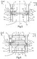
- the projection 19 is obtained simultaneously during the formation of the cavity from the deformation of the internal surface 12 of the collector 3, whether it is the internal surface 12 participating in the cover 14 as shown in the figures 3 and 5 or of the participating internal surface 12 of the collector plate 15, as shown in the figures 4 and 6 .
- the cavity 18 and the projection 19 are respectively point deformations of the internal face 12 of the collector 3. It is understood in this that the cavity 18 and the projection 19 are extended over small surfaces of the internal face 12, and are for example obtained from a punching of the internal surface 12 in particular carried out using a punch at the tapered end.
- the cavity 18 and the projection 19 are lateral deformations of the internal face 12 of the manifold 3, and are for example obtained with a punch, one end of which extends inside a lateral plane of the collector 3.
- the cavity 18 is formed along a deformation axis A2 which is orthogonal to the direction of longitudinal extension A1 of the collector 3.
- a depth P of the cavity 18 taken between the internal face 12 of the collector 3 and a bottom of the cavity 20 is less than a thickness E of the manifold 3 taken between the internal face 12 and the external face 13 of the manifold 3. In this case, the cavity 18 does not open out through the external face 13 of the manifold 3.
- a depth P of the cavity 18 taken between the internal face 12 of the manifold 3 and a cavity bottom 20 is equal to a thickness E of the manifold 3 taken between the internal face 12 and the external face 13 of the manifold 3.
- the cavity 18 opens out through the internal face 12 and the external face 13 of the manifold 3.
- the cavity 18 can be a cutout of the cover 14 or of the collector plate 15.
- the cover 14 comprising at least one cover flank 14b terminated by a cover slice 14c, the cavity 18 is provided at least straddling the cover slice 14c.
- the collector plate 15 comprising at least one side of the plate 15b terminated by a wafer of plate 15c, the cavity 18 is provided at least astride the wafer of plate 15c.
- a distance D taken between a proximal edge 21 of the housing 16 for receiving the partition 10 and the deformation axis A2 is equal to the thickness E of the manifold 3 to within +/- 10%.
- the cavity 18 is made near the housing 16 for receiving the partition 10, so that the projection 19 resulting from the formation of the cavity 18 borders, or even encroaches on, the housing 16, so as to immobilize the partition 10 inside the housing 16 in a position such that the partition 10 is arranged perpendicular to the longitudinal axis of extension A1 of the manifold 3.
- the cavities 18 and the projections 19 are four in number and are symmetrically distributed at the corners of a quadrilateral housing the partition 10. According to this configuration, the cavities 18 and the projections 19 are made on the internal face 12 constituting the cover 14 .
- the cavities 18 and the projections 19 are two in number and are symmetrically distributed with respect to a center of symmetry 22 of the partition 10. According to this configuration, the cavities 18 and the projections 19 are made on the internal face 12 constituting the cover 14. A first pair of cavity and protrusion is thus provided on one side of the partition 10, and a second pair of cavity and protrusion is provided on the other side of the partition 10.
- the cavities 18 and the projections 19 are four in number and are symmetrically distributed at the angles of a quadrilateral housing the partition 10. According to this configuration, the cavities 18 and the projections 19 are made on the internal face 12 constituting the plate collector 15.
- the cavities 18 and the projections 19 are two in number and are symmetrically distributed with respect to a center of symmetry 22 of the partition 10. According to this configuration, the cavities 18 and the projections 19 are made on the internal face 12 constituting the the collector plate 15.
- the cavities 18 of the embodiments of the figures 5 and 6 are obstructed by the presence of the collector plate 15, when these are formed in the cover 14. The same applies to the case where the cavities 18 are formed in the collector plate 15 and closed by the cover 14. In all In these cases, the cavity is configured to fill and be sealed by a layer of filler material present on the cover and / or on the collector plate, once the heat exchanger passes into the furnace.
- the assembly process can be completed by a fourth step of securing the cover 14 and the separator plate 15, the partition 10 being interposed between the cover 14 and the collector plate 15.
Landscapes
- Engineering & Computer Science (AREA)
- Physics & Mathematics (AREA)
- Thermal Sciences (AREA)
- Mechanical Engineering (AREA)
- General Engineering & Computer Science (AREA)
- Heat-Exchange Devices With Radiators And Conduit Assemblies (AREA)
Claims (11)
- Endboden (3) für einen Wärmetauscher (1), wobei der Endboden (3) mindestens eine Sammelplatte (15) und einen Deckel (14), die gemeinsam einen Innenraum (11) begrenzen, und mindestens eine Trennwand (10) enthält, die den Innenraum (11) in zwei Abschnitte (11a, 11b) teilt, wobei der Endboden (3) eine den Innenraum (11) umrandende Innenseite (12) und eine Außenseite (13) aufweist, die zur Außenseite des Endbodens (3) gerichtet ist, wobei die Innenseite (12) mindestens eine Aufnahme (16) zum Empfang der Trennwand (10) enthält, dadurch gekennzeichnet, dass die Innenseite (12) mindestens einen Hohlraum (18) und einen Vorsprung (19) aufweist, wobei der Vorsprung (19) zwischen den Hohlraum (18) und die Aufnahme (16) zum Empfang der Trennwand (10) eingefügt ist, und dass der Vorsprung (19) eine Einrichtung zum Halt der Trennwand (10) in Stellung gemäß einer Trennwandebene (P2) bildet, die orthogonal zu einer Längsausdehnungsrichtung (A1) des Endbodens (3) ist.
- Endboden (3) nach Anspruch 1, dadurch gekennzeichnet, dass der Vorsprung (19) aus dem Werkstoff der Innenseite (12) des Endbodens (3) besteht.
- Endboden (3) nach einem der vorhergehenden Ansprüche, dadurch gekennzeichnet, dass eine Tiefe (P) des Hohlraums (18) gemessen zwischen der Innenseite (12) des Endbodens (3) und einem Hohlraumboden (20) geringer als eine Dicke (E) des Endbodens (3) gemessen zwischen der Innenseite (12) und der Außenseite (13) des Endbodens (3) ist.
- Endboden (3) nach einem der Ansprüche 1 bis 2, dadurch gekennzeichnet, dass der Hohlraum (18) durch die Außenseite (13) hindurch mündet.
- Endboden (3) nach einem der vorhergehenden Ansprüche, dadurch gekennzeichnet, dass der Deckel (14) mindestens einen von zwei Deckelflanken (14b) umrandeten Deckelboden (14a) enthält, wobei mindestens eine der Deckelflanken (14b) in einer Deckelschmalseite (14c) endet, und dass der Hohlraum (18) mindestens die Deckelschmalseite (14c) übergreifend ausgespart ist.
- Endboden (3) nach einem der Ansprüche 1 bis 4, dadurch gekennzeichnet, dass die Sammelplatte (15) mindestens einen von zwei Plattenflanken (15b) umrandeten Plattenboden (15a) enthält, wobei mindestens eine der Plattenflanken (15b) in einer Plattenschmalseite (15c) endet, und dadurch gekennzeichnet, dass der Hohlraum (18) mindestens die Plattenschmalseite (15c) übergreifend ausgespart ist.
- Endboden (3) nach einem der vorhergehenden Ansprüche, dadurch gekennzeichnet, dass die Innenseite (12) mindestens ein Paar aus Hohlraum (18) und Vorsprung (19) aufweist.
- Endboden (3) nach dem vorhergehenden Anspruch, der eine Vielzahl von Paaren aus Hohlraum (18) und Vorsprung (19) enthält, wobei diese Paare bezüglich einer Längsausdehnungsrichtung (A1) des Endbodens (3) diametral entgegengesetzt liegen.
- Endboden (3) nach Anspruch 7 oder 8, der mindestens zwei Paare aus Hohlraum (18) und Vorsprung (19) enthält, wobei diese zwei Paare symmetrisch bezüglich eines Symmetriezentrums (22) der Trennwand (10) angeordnet sind.
- Wärmetauscher (1), der mindestens einen Endboden (3) nach einem der vorhergehenden Ansprüche enthält.
- Verfahren zum Zusammenbau eines Endbodens (3) nach einem der Ansprüche 1 bis 9, dadurch gekennzeichnet, dass das Zusammenbauverfahren nacheinander mindestens die folgenden Schritte enthält:- einen ersten Schritt der Herstellung der Aufnahme (16) auf der Innenseite (12) des Endbodens (3),- einen zweiten Schritt des Einsetzens der Trennwand (10) im Inneren der Aufnahme (16), die für ihren Empfang vorgesehen ist,- einen dritten Schritt der Herstellung des Hohlraums (18) und des Vorsprungs (19) im Inneren der Innenseite (12) des Endbodens (3).
Priority Applications (2)
| Application Number | Priority Date | Filing Date | Title |
|---|---|---|---|
| EP18210197.2A EP3663695B1 (de) | 2018-12-04 | 2018-12-04 | Konstitutiver sammelbehälter für einen wärmetauscher |
| PCT/EP2019/083496 WO2020115043A1 (en) | 2018-12-04 | 2019-12-03 | Constituent header of a heat exchanger |
Applications Claiming Priority (1)
| Application Number | Priority Date | Filing Date | Title |
|---|---|---|---|
| EP18210197.2A EP3663695B1 (de) | 2018-12-04 | 2018-12-04 | Konstitutiver sammelbehälter für einen wärmetauscher |
Publications (2)
| Publication Number | Publication Date |
|---|---|
| EP3663695A1 EP3663695A1 (de) | 2020-06-10 |
| EP3663695B1 true EP3663695B1 (de) | 2021-08-18 |
Family
ID=64606750
Family Applications (1)
| Application Number | Title | Priority Date | Filing Date |
|---|---|---|---|
| EP18210197.2A Active EP3663695B1 (de) | 2018-12-04 | 2018-12-04 | Konstitutiver sammelbehälter für einen wärmetauscher |
Country Status (2)
| Country | Link |
|---|---|
| EP (1) | EP3663695B1 (de) |
| WO (1) | WO2020115043A1 (de) |
Family Cites Families (4)
| Publication number | Priority date | Publication date | Assignee | Title |
|---|---|---|---|---|
| US5586600A (en) * | 1994-10-26 | 1996-12-24 | Valeo Engine Cooling, Inc. | Heat exchanger |
| JPH09269199A (ja) * | 1996-03-29 | 1997-10-14 | Sanden Corp | 熱交換器 |
| EP1767889A2 (de) * | 2005-09-21 | 2007-03-28 | Calsonic Kansei Corporation | Wärmetauscher |
| FR3013436B1 (fr) * | 2013-11-18 | 2018-12-07 | Valeo Systemes Thermiques | Collecteur pour echangeur de chaleur |
-
2018
- 2018-12-04 EP EP18210197.2A patent/EP3663695B1/de active Active
-
2019
- 2019-12-03 WO PCT/EP2019/083496 patent/WO2020115043A1/en active Application Filing
Also Published As
| Publication number | Publication date |
|---|---|
| EP3663695A1 (de) | 2020-06-10 |
| WO2020115043A1 (en) | 2020-06-11 |
Similar Documents
| Publication | Publication Date | Title |
|---|---|---|
| EP2513585B1 (de) | Wärmetauscher | |
| EP3011247B1 (de) | Rohr mit einem behälter aus phasenwechselmaterial für ein wärmetauschbündel, insbesondere für einen verdampfer eines klimaanlagensystems eines fahrzeugs | |
| EP3423770B1 (de) | Vorratsbehälter für phasenwechselmaterial mit einem füllrohr zum befüllen desselben für einen wärmetauscher einer kraftfahrzeug-klimaanlage | |
| EP2972049B1 (de) | Wärmetauscher, insbesondere supraladender luftkühler | |
| FR2947331A1 (fr) | Echangeur de chaleur comprenant un faisceau de tubes avec au moins un tube inactif | |
| EP3663695B1 (de) | Konstitutiver sammelbehälter für einen wärmetauscher | |
| EP1015838B1 (de) | Wärmetauscher für kraftfahrzeuge und verfahren zu deren herstellung | |
| EP3555545A1 (de) | Wärmetauscher mit verstärkungsplatte | |
| EP3577408B1 (de) | Wärmetauscherkopf | |
| WO2014016192A1 (fr) | Echangeur de chaleur pour vehicule automobile comportant une bride de fixation | |
| FR3068121A1 (fr) | Echangeur de chaleur a reservoir de materiau a changement de phase comprenant une languette de maintien et d'obturation d'un tube de remplissage | |
| EP3384224A1 (de) | Kraftfahrzeugwärmetauscher mit einem ausgleichsbehälter | |
| EP3628954B1 (de) | Wärmetauscher mit einem behälter für phasenwechselmaterial, und entsprechendes herstellungsverfahren | |
| EP2936032A1 (de) | Wärmetauscherelement und entsprechender wärmetauscher | |
| FR3069312B1 (fr) | Echangeur de chaleur pour refroidisseur d'air de suralimentation | |
| EP2901097B1 (de) | Wärmetauscher, insbesondere für kraftfahrzeug, und dazugehöriges montageverfahren | |
| EP3568658B1 (de) | Heizkörper mit einer nach aussen gerichteten u-förmigen endplatte und entsprechende heiz-, lüftungs- oder klimatisierungssystem | |
| FR3060724A1 (fr) | Echangeur thermique, notamment evaporateur, muni d'un dispositif de raccordement pour l'introduction et l'extraction d'un fluide caloporteur. | |
| FR3079290A1 (fr) | Echangeur thermique a reservoir(s) de materiau a changement de phase comprenant un ou plusieurs organes de remplissage | |
| EP3430341A1 (de) | Wärmetauscher und zugehöriges herstellungsverfahren | |
| FR3086045A1 (fr) | Echangeur de chaleur a reservoir de materiau a changement de phase et procede de fabrication associe | |
| FR3108395A1 (fr) | Echangeur thermique pour véhicule automobile | |
| FR3088710A1 (fr) | Echangeur de chaleur pour vehicule automobile | |
| FR3106000A1 (fr) | Échangeur de chaleur à tubes comportant des intercalaires | |
| FR3086043A1 (fr) | Echangeur de chaleur a reservoir de materiau a changement de phase et procede de fabrication |
Legal Events
| Date | Code | Title | Description |
|---|---|---|---|
| PUAI | Public reference made under article 153(3) epc to a published international application that has entered the european phase |
Free format text: ORIGINAL CODE: 0009012 |
|
| STAA | Information on the status of an ep patent application or granted ep patent |
Free format text: STATUS: THE APPLICATION HAS BEEN PUBLISHED |
|
| AK | Designated contracting states |
Kind code of ref document: A1 Designated state(s): AL AT BE BG CH CY CZ DE DK EE ES FI FR GB GR HR HU IE IS IT LI LT LU LV MC MK MT NL NO PL PT RO RS SE SI SK SM TR |
|
| AX | Request for extension of the european patent |
Extension state: BA ME |
|
| STAA | Information on the status of an ep patent application or granted ep patent |
Free format text: STATUS: REQUEST FOR EXAMINATION WAS MADE |
|
| 17P | Request for examination filed |
Effective date: 20201210 |
|
| RBV | Designated contracting states (corrected) |
Designated state(s): AL AT BE BG CH CY CZ DE DK EE ES FI FR GB GR HR HU IE IS IT LI LT LU LV MC MK MT NL NO PL PT RO RS SE SI SK SM TR |
|
| GRAP | Despatch of communication of intention to grant a patent |
Free format text: ORIGINAL CODE: EPIDOSNIGR1 |
|
| STAA | Information on the status of an ep patent application or granted ep patent |
Free format text: STATUS: GRANT OF PATENT IS INTENDED |
|
| INTG | Intention to grant announced |
Effective date: 20210319 |
|
| RAP3 | Party data changed (applicant data changed or rights of an application transferred) |
Owner name: VALEO SYSTEMES THERMIQUES |
|
| RIN1 | Information on inventor provided before grant (corrected) |
Inventor name: XU, BINGLIN Inventor name: HE, RONGXIN Inventor name: BUN, LIM-SUON Inventor name: RABAHI, SALIM Inventor name: CUILLIER, JEAN-BAPTISTE |
|
| GRAS | Grant fee paid |
Free format text: ORIGINAL CODE: EPIDOSNIGR3 |
|
| GRAA | (expected) grant |
Free format text: ORIGINAL CODE: 0009210 |
|
| STAA | Information on the status of an ep patent application or granted ep patent |
Free format text: STATUS: THE PATENT HAS BEEN GRANTED |
|
| AK | Designated contracting states |
Kind code of ref document: B1 Designated state(s): AL AT BE BG CH CY CZ DE DK EE ES FI FR GB GR HR HU IE IS IT LI LT LU LV MC MK MT NL NO PL PT RO RS SE SI SK SM TR |
|
| REG | Reference to a national code |
Ref country code: GB Ref legal event code: FG4D Free format text: NOT ENGLISH |
|
| REG | Reference to a national code |
Ref country code: CH Ref legal event code: EP |
|
| REG | Reference to a national code |
Ref country code: DE Ref legal event code: R096 Ref document number: 602018021952 Country of ref document: DE |
|
| REG | Reference to a national code |
Ref country code: IE Ref legal event code: FG4D Free format text: LANGUAGE OF EP DOCUMENT: FRENCH Ref country code: AT Ref legal event code: REF Ref document number: 1422010 Country of ref document: AT Kind code of ref document: T Effective date: 20210915 |
|
| REG | Reference to a national code |
Ref country code: LT Ref legal event code: MG9D |
|
| REG | Reference to a national code |
Ref country code: NL Ref legal event code: MP Effective date: 20210818 |
|
| REG | Reference to a national code |
Ref country code: AT Ref legal event code: MK05 Ref document number: 1422010 Country of ref document: AT Kind code of ref document: T Effective date: 20210818 |
|
| PG25 | Lapsed in a contracting state [announced via postgrant information from national office to epo] |
Ref country code: PT Free format text: LAPSE BECAUSE OF FAILURE TO SUBMIT A TRANSLATION OF THE DESCRIPTION OR TO PAY THE FEE WITHIN THE PRESCRIBED TIME-LIMIT Effective date: 20211220 Ref country code: NO Free format text: LAPSE BECAUSE OF FAILURE TO SUBMIT A TRANSLATION OF THE DESCRIPTION OR TO PAY THE FEE WITHIN THE PRESCRIBED TIME-LIMIT Effective date: 20211118 Ref country code: BG Free format text: LAPSE BECAUSE OF FAILURE TO SUBMIT A TRANSLATION OF THE DESCRIPTION OR TO PAY THE FEE WITHIN THE PRESCRIBED TIME-LIMIT Effective date: 20211118 Ref country code: AT Free format text: LAPSE BECAUSE OF FAILURE TO SUBMIT A TRANSLATION OF THE DESCRIPTION OR TO PAY THE FEE WITHIN THE PRESCRIBED TIME-LIMIT Effective date: 20210818 Ref country code: LT Free format text: LAPSE BECAUSE OF FAILURE TO SUBMIT A TRANSLATION OF THE DESCRIPTION OR TO PAY THE FEE WITHIN THE PRESCRIBED TIME-LIMIT Effective date: 20210818 Ref country code: RS Free format text: LAPSE BECAUSE OF FAILURE TO SUBMIT A TRANSLATION OF THE DESCRIPTION OR TO PAY THE FEE WITHIN THE PRESCRIBED TIME-LIMIT Effective date: 20210818 Ref country code: SE Free format text: LAPSE BECAUSE OF FAILURE TO SUBMIT A TRANSLATION OF THE DESCRIPTION OR TO PAY THE FEE WITHIN THE PRESCRIBED TIME-LIMIT Effective date: 20210818 Ref country code: FI Free format text: LAPSE BECAUSE OF FAILURE TO SUBMIT A TRANSLATION OF THE DESCRIPTION OR TO PAY THE FEE WITHIN THE PRESCRIBED TIME-LIMIT Effective date: 20210818 Ref country code: ES Free format text: LAPSE BECAUSE OF FAILURE TO SUBMIT A TRANSLATION OF THE DESCRIPTION OR TO PAY THE FEE WITHIN THE PRESCRIBED TIME-LIMIT Effective date: 20210818 Ref country code: HR Free format text: LAPSE BECAUSE OF FAILURE TO SUBMIT A TRANSLATION OF THE DESCRIPTION OR TO PAY THE FEE WITHIN THE PRESCRIBED TIME-LIMIT Effective date: 20210818 |
|
| PG25 | Lapsed in a contracting state [announced via postgrant information from national office to epo] |
Ref country code: PL Free format text: LAPSE BECAUSE OF FAILURE TO SUBMIT A TRANSLATION OF THE DESCRIPTION OR TO PAY THE FEE WITHIN THE PRESCRIBED TIME-LIMIT Effective date: 20210818 Ref country code: LV Free format text: LAPSE BECAUSE OF FAILURE TO SUBMIT A TRANSLATION OF THE DESCRIPTION OR TO PAY THE FEE WITHIN THE PRESCRIBED TIME-LIMIT Effective date: 20210818 Ref country code: GR Free format text: LAPSE BECAUSE OF FAILURE TO SUBMIT A TRANSLATION OF THE DESCRIPTION OR TO PAY THE FEE WITHIN THE PRESCRIBED TIME-LIMIT Effective date: 20211119 |
|
| PG25 | Lapsed in a contracting state [announced via postgrant information from national office to epo] |
Ref country code: NL Free format text: LAPSE BECAUSE OF FAILURE TO SUBMIT A TRANSLATION OF THE DESCRIPTION OR TO PAY THE FEE WITHIN THE PRESCRIBED TIME-LIMIT Effective date: 20210818 |
|
| PG25 | Lapsed in a contracting state [announced via postgrant information from national office to epo] |
Ref country code: DK Free format text: LAPSE BECAUSE OF FAILURE TO SUBMIT A TRANSLATION OF THE DESCRIPTION OR TO PAY THE FEE WITHIN THE PRESCRIBED TIME-LIMIT Effective date: 20210818 |
|
| REG | Reference to a national code |
Ref country code: DE Ref legal event code: R097 Ref document number: 602018021952 Country of ref document: DE |
|
| PG25 | Lapsed in a contracting state [announced via postgrant information from national office to epo] |
Ref country code: SM Free format text: LAPSE BECAUSE OF FAILURE TO SUBMIT A TRANSLATION OF THE DESCRIPTION OR TO PAY THE FEE WITHIN THE PRESCRIBED TIME-LIMIT Effective date: 20210818 Ref country code: SK Free format text: LAPSE BECAUSE OF FAILURE TO SUBMIT A TRANSLATION OF THE DESCRIPTION OR TO PAY THE FEE WITHIN THE PRESCRIBED TIME-LIMIT Effective date: 20210818 Ref country code: RO Free format text: LAPSE BECAUSE OF FAILURE TO SUBMIT A TRANSLATION OF THE DESCRIPTION OR TO PAY THE FEE WITHIN THE PRESCRIBED TIME-LIMIT Effective date: 20210818 Ref country code: EE Free format text: LAPSE BECAUSE OF FAILURE TO SUBMIT A TRANSLATION OF THE DESCRIPTION OR TO PAY THE FEE WITHIN THE PRESCRIBED TIME-LIMIT Effective date: 20210818 Ref country code: CZ Free format text: LAPSE BECAUSE OF FAILURE TO SUBMIT A TRANSLATION OF THE DESCRIPTION OR TO PAY THE FEE WITHIN THE PRESCRIBED TIME-LIMIT Effective date: 20210818 Ref country code: AL Free format text: LAPSE BECAUSE OF FAILURE TO SUBMIT A TRANSLATION OF THE DESCRIPTION OR TO PAY THE FEE WITHIN THE PRESCRIBED TIME-LIMIT Effective date: 20210818 |
|
| PLBE | No opposition filed within time limit |
Free format text: ORIGINAL CODE: 0009261 |
|
| STAA | Information on the status of an ep patent application or granted ep patent |
Free format text: STATUS: NO OPPOSITION FILED WITHIN TIME LIMIT |
|
| REG | Reference to a national code |
Ref country code: DE Ref legal event code: R119 Ref document number: 602018021952 Country of ref document: DE |
|
| 26N | No opposition filed |
Effective date: 20220519 |
|
| PG25 | Lapsed in a contracting state [announced via postgrant information from national office to epo] |
Ref country code: MC Free format text: LAPSE BECAUSE OF FAILURE TO SUBMIT A TRANSLATION OF THE DESCRIPTION OR TO PAY THE FEE WITHIN THE PRESCRIBED TIME-LIMIT Effective date: 20210818 Ref country code: IT Free format text: LAPSE BECAUSE OF FAILURE TO SUBMIT A TRANSLATION OF THE DESCRIPTION OR TO PAY THE FEE WITHIN THE PRESCRIBED TIME-LIMIT Effective date: 20210818 |
|
| REG | Reference to a national code |
Ref country code: CH Ref legal event code: PL |
|
| PG25 | Lapsed in a contracting state [announced via postgrant information from national office to epo] |
Ref country code: SI Free format text: LAPSE BECAUSE OF FAILURE TO SUBMIT A TRANSLATION OF THE DESCRIPTION OR TO PAY THE FEE WITHIN THE PRESCRIBED TIME-LIMIT Effective date: 20210818 |
|
| REG | Reference to a national code |
Ref country code: BE Ref legal event code: MM Effective date: 20211231 |
|
| PG25 | Lapsed in a contracting state [announced via postgrant information from national office to epo] |
Ref country code: LU Free format text: LAPSE BECAUSE OF NON-PAYMENT OF DUE FEES Effective date: 20211204 Ref country code: IE Free format text: LAPSE BECAUSE OF NON-PAYMENT OF DUE FEES Effective date: 20211204 Ref country code: DE Free format text: LAPSE BECAUSE OF NON-PAYMENT OF DUE FEES Effective date: 20220701 |
|
| PG25 | Lapsed in a contracting state [announced via postgrant information from national office to epo] |
Ref country code: FR Free format text: LAPSE BECAUSE OF NON-PAYMENT OF DUE FEES Effective date: 20211231 Ref country code: BE Free format text: LAPSE BECAUSE OF NON-PAYMENT OF DUE FEES Effective date: 20211231 |
|
| PG25 | Lapsed in a contracting state [announced via postgrant information from national office to epo] |
Ref country code: LI Free format text: LAPSE BECAUSE OF NON-PAYMENT OF DUE FEES Effective date: 20211231 Ref country code: CH Free format text: LAPSE BECAUSE OF NON-PAYMENT OF DUE FEES Effective date: 20211231 |
|
| PG25 | Lapsed in a contracting state [announced via postgrant information from national office to epo] |
Ref country code: CY Free format text: LAPSE BECAUSE OF FAILURE TO SUBMIT A TRANSLATION OF THE DESCRIPTION OR TO PAY THE FEE WITHIN THE PRESCRIBED TIME-LIMIT Effective date: 20210818 |
|
| P01 | Opt-out of the competence of the unified patent court (upc) registered |
Effective date: 20230528 |
|
| PG25 | Lapsed in a contracting state [announced via postgrant information from national office to epo] |
Ref country code: HU Free format text: LAPSE BECAUSE OF FAILURE TO SUBMIT A TRANSLATION OF THE DESCRIPTION OR TO PAY THE FEE WITHIN THE PRESCRIBED TIME-LIMIT; INVALID AB INITIO Effective date: 20181204 |
|
| GBPC | Gb: european patent ceased through non-payment of renewal fee |
Effective date: 20221204 |
|
| PG25 | Lapsed in a contracting state [announced via postgrant information from national office to epo] |
Ref country code: GB Free format text: LAPSE BECAUSE OF NON-PAYMENT OF DUE FEES Effective date: 20221204 |
|
| PG25 | Lapsed in a contracting state [announced via postgrant information from national office to epo] |
Ref country code: MK Free format text: LAPSE BECAUSE OF FAILURE TO SUBMIT A TRANSLATION OF THE DESCRIPTION OR TO PAY THE FEE WITHIN THE PRESCRIBED TIME-LIMIT Effective date: 20210818 |