EP3663647B1 - Verbrennungsanlage mit einer düse, reaktor zur reinigung von abgasen mit einer düse - Google Patents
Verbrennungsanlage mit einer düse, reaktor zur reinigung von abgasen mit einer düse Download PDFInfo
- Publication number
- EP3663647B1 EP3663647B1 EP18211081.7A EP18211081A EP3663647B1 EP 3663647 B1 EP3663647 B1 EP 3663647B1 EP 18211081 A EP18211081 A EP 18211081A EP 3663647 B1 EP3663647 B1 EP 3663647B1
- Authority
- EP
- European Patent Office
- Prior art keywords
- nozzle
- reactor
- helically shaped
- shaped guiding
- guiding element
- Prior art date
- Legal status (The legal status is an assumption and is not a legal conclusion. Google has not performed a legal analysis and makes no representation as to the accuracy of the status listed.)
- Active
Links
Images
Classifications
-
- F—MECHANICAL ENGINEERING; LIGHTING; HEATING; WEAPONS; BLASTING
- F23—COMBUSTION APPARATUS; COMBUSTION PROCESSES
- F23L—SUPPLYING AIR OR NON-COMBUSTIBLE LIQUIDS OR GASES TO COMBUSTION APPARATUS IN GENERAL ; VALVES OR DAMPERS SPECIALLY ADAPTED FOR CONTROLLING AIR SUPPLY OR DRAUGHT IN COMBUSTION APPARATUS; INDUCING DRAUGHT IN COMBUSTION APPARATUS; TOPS FOR CHIMNEYS OR VENTILATING SHAFTS; TERMINALS FOR FLUES
- F23L9/00—Passages or apertures for delivering secondary air for completing combustion of fuel
- F23L9/02—Passages or apertures for delivering secondary air for completing combustion of fuel by discharging the air above the fire
-
- F—MECHANICAL ENGINEERING; LIGHTING; HEATING; WEAPONS; BLASTING
- F23—COMBUSTION APPARATUS; COMBUSTION PROCESSES
- F23J—REMOVAL OR TREATMENT OF COMBUSTION PRODUCTS OR COMBUSTION RESIDUES; FLUES
- F23J15/00—Arrangements of devices for treating smoke or fumes
- F23J15/003—Arrangements of devices for treating smoke or fumes for supplying chemicals to fumes, e.g. using injection devices
-
- F—MECHANICAL ENGINEERING; LIGHTING; HEATING; WEAPONS; BLASTING
- F23—COMBUSTION APPARATUS; COMBUSTION PROCESSES
- F23J—REMOVAL OR TREATMENT OF COMBUSTION PRODUCTS OR COMBUSTION RESIDUES; FLUES
- F23J2219/00—Treatment devices
- F23J2219/60—Sorption with dry devices, e.g. beds
Definitions
- the present invention relates to an incineration plant comprising a nozzle having a gas inlet and a gas outlet as well as to a reactor for cleaning flue gases by a dry or quasi-dry sorption process comprising a nozzle having a gas inlet and a gas outlet.
- the incineration plant for combusting solid material comprises a combustion chamber, a combustion material inlet through which solid material can be introduced into the combustion chamber, a combustion grate with which the solid material and combusted solid material can be conveyed through the combustion chamber, a primary air supply below the top of the combustion grate and at least one nozzle arranged above the combustion grate, with which secondary air and/or an oxygen poor carrier gas can be provided, wherein the nozzle has a gas inlet and a gas outlet.
- the solid material to be combusted is introduced via the inlet into the combustion chamber and is conveyed by the combustion grate towards an outlet on the opposite side of the combustion chamber.
- the inventive nozzle may be used in an incineration plant in which flue gases (German: Rezigas) may be recirculated.
- flue gases German: Rezigas
- Such an incineration plant and method is known from DE 10 2004 037 442 B4 , according to which the recirculated flue gas is provided by a two substance nozzle with a central nozzle section and an outer nozzle section.
- the invention also relates to a nozzle used in a reactor for cleaning (in particular desulfurizing) flue gases by a dry or quasi-dry sorption process, the reactor comprising a flue gas inlet at the bottom of the reactor, an outlet at the top of the reactor, a dry sorbent injection system with at least one dry sorbent nozzle for injecting dry sorbent into the reactor, the at least one nozzle being arranged between the flue gas inlet and the outlet.
- the combustion gases produced in a combustion chamber are usually introduced as flue gas through the flue gas inlet into the reactor.
- a dry sorbent is injected into the flue gas, for example calcium oxide or calcium hydroxide powder is injected into the flue gas.
- the dry sorbent powder can be injected as particles together with a carrier gas through a nozzle according to the present invention.
- the carrier gas and the dry sorbent powder is mixed with the flue gas, wherein the dry sorbent containing flue gas may be forced through a venturi system, so that a so called fluidized bed is formed downstream of the venturi system in order to enhance the sorption process.
- the dry sorbent is usually injected by a nozzle arranged at the wall of the reactor, so that the highest dry sorbent concentration is at the outer circumference of the reactor at the injection side.
- a reactor with the above described features is for example known from CN 101 402 019 B .
- US 2,613,481 discloses a pressure regulating valve
- US 2016/0258685 A1 discloses a dispersion apparatus for use with a solid fuel burner
- EP 0 543 705 A1 discloses an injection head for dispersion of a powder in a desulfurization chamber of a heat generator and therefore a reactor according to the preamble of claim 2.
- US 5,503,089 discloses an incineration plant with the features of the preamble of claim 1.
- the secondary air and/or oxygen poor gas i.e. recirculated flue gas
- the dry sorbent powder provided with a carrier gas stream to the reactor for cleaning (desulfurization) of flue gases is more efficiently mixed with the flue gases.
- flow properties of the gases i.e. pure gases, gas mixture, carrier gases with particles
- the gases i.e. pure gases, gas mixture, carrier gases with particles
- the nozzle has a helically shaped guiding element, which helically shaped guiding element is arranged between the gas inlet and the gas outlet of the nozzle for impinging a swirl to the gas, wherein the helically shaped guiding element has a front edge and a back edge, the front edge and the back edge being displaced with a distance to each other in a longitudinal direction of the nozzle.
- the gas stream provided to the gas (nozzle) inlet is forced into a helically shaped movement (trajectory), so that the gas stream, which leaves the gas (nozzle) outlet comprises a swirl (angular momentum).
- the gas stream, which leaves the gas (nozzle) outlet comprises a swirl (angular momentum).
- the degree of the swirl is characterized by the so called swirl number.
- the front edge of a helically shaped guiding element is that edge, which is assigned to the gas (nozzle) inlet and the back edge is that edge of the helically shaped guiding element, which is assigned to the gas (nozzle) outlet.
- the helically shaped guiding element extends continuously from the front edge to the back edged.
- a helically shaped guiding element comprises multiple sections, which are arranged behind each other.
- the front edge is arranged in the plane of the gas (nozzle) inlet or downstream of the gas inlet (inside the nozzle), while the back edge of the helically shaped guiding element is arranged upstream or in the plane of the gas (nozzle) outlet.
- at least the back edge is arranged downstream of the nozzle, in particular outside of an outer tube of the nozzle, so that the helically shaped guiding element extends over the nozzle body.
- the helically shaped guiding element might extend only over a part of a flow cross section (flow channel) of the nozzle, in which case the helically shaped guiding element may extend from an outer wall or from an inner wall into the flow channel of the nozzle. But, preferably the helically shaped guiding element extends over the whole flow cross section of the respective flow channel of the nozzle, thereby forcing the complete gas stream on a helically shaped trajectory through the nozzle.
- the helically shaped guiding element extends at least 360° around a central (imaginary) axis, so that one helically shaped guiding element covers the whole cross section of the respective flow channel of the nozzle.
- Each nozzle or each flow channel of the nozzle may have exactly one or more than one helically shaped guiding element, for example two, three or four helically shaped guiding elements, which are arranged parallel to each other.
- the front edge and the back edge of each of this multiple helically shaped guiding elements may be arranged in a respective plane so that all of the helically shaped guiding elements extend over the same length of the nozzle. But, it may also be possible, that some of the multiple helically shaped guiding elements are shorter than other helically shaped guiding elements.
- the nozzle body is provided by a tube like structure, wherein the helically shaped guiding element is arranged in the tube like structure.
- the helically shaped guiding element is flexible and that the nozzle has a setting element embodied to alter the distance between the front edge and the back edge of the helically shaped guiding element.
- the helically shaped guiding element is compressed or uncompressed in the longitudinal direction of the nozzle, so that the pitch (slope) of the helically shaped guiding element is altered, whereby the trajectory of the gas and thereby the swirl number can be altered.
- the helically shaped guiding element is flexible and the nozzle has a setting element embodied to alter the distance between the front edge and the back edge of the helically shaped guiding element.
- the helically shaped guiding element can be made of an elastic material or can be formed by a (rubber or metal) sheet, which can be deformed elastically.
- the setting element can be embodied by a rod or tube, to which the helically shaped guiding element is directly or indirectly attached at its front or back, wherein the setting element can be displaced in the longitudinal direction of the nozzle.
- the rod may be arranged centrally within the nozzle, so that the helically shaped guiding element extends around the rod.
- a tubelike setting element may surround at least a part of the helically shaped guiding element.
- the front or back of the helically shaped guiding element is stationary fixed to a stationary part of the nozzle (such as the nozzle body), while the back or the front is fixed to the setting element, which can be displaced in the longitudinal direction of the nozzle, in particular relative to the nozzle body.
- the setting element might be actuated manually, for example by a manually displaceable setting wheel, or by an electronically controllable actuator.
- the actuator may be an electrical, pneumatically or hydraulically driven motor. While a manually actuatable setting element is preferable to alter the guiding element between two operation periods, the helically shaped guiding element might be altered by the electronically controllable actuator even during operation.
- the invention is in particular suitable for a nozzle having only one flow channel for one gas (pure gas, gas mixture, carrier gas with solid particles), wherein the helically shaped guiding element is arranged in the one flow channel.
- the invention can also be applied to a multiple substance nozzle, wherein more than one flow channel for different gases (mixtures) are embodied, each flow channel being connectable to different gas sources.
- a helically shaped guiding element might be arranged in only one, multiple or all flow channels of the multiple substance nozzle.
- the invention is applicable to a two-substance nozzle, in which the nozzle has a central flow channel and an outer flow channel surrounding the central flow channel, wherein a helically shaped guiding element is arranged in the central flow channel and/or in the outer flow channel.
- the helically shaped guiding elements assigned to the different flow channels may be altered independently of each other. With such a multiple substance nozzle there is a higher degree of flexibility for altering the parameters with which the gas or gases can be supplied to the medium.
- recirculated flue gas or other oxygen poor carrier gas may be provided through one flow channel, while secondary air may be provided through the other flow channel.
- the incineration plant has preferable more than four, in particular at least six or even at least twelve nozzles according to the invention, which are preferable arranged in a horizontal plane within the combustion chamber.
- the reactor according to the present invention is preferable arranged in a vertical manner, wherein the flue gas inlet is arranged at the very bottom of the reactor, meaning that there is preferable no mean for collecting residuals below the flue gas inlet.
- the flue gas is provided through a duct from a combustion chamber, which duct leads in horizontal manner to the flue gas inlet of the reactor.
- the flue gas outlet is arranged vertically above the flue gas inlet, so that the reactor can be considered that part, in which the flue gas advances vertically from the bottom to the top.
- the reactor is delimited by a reactor wall.
- a dry sorbent (i.e. CaO or Ca(OH) 2 ) powder is provided through the nozzle of the dry sorbent injection system into the reactor. It is preferred, that more than one dry sorbent nozzle is arranged at the reactor wall. For example, three, four or more nozzles are arranged in preferably one horizontal plane.
- dry sorbent nozzles are arranged above each other.
- the outlet of the (dry sorbent) nozzles may be arranged with a distance from the wall, so that the dry sorbent does not contact the wall of the reactor immediately after injection.
- the (dry sorbent) nozzles may be arranged below a venturi nozzle or below multiple venturi systems for the flue gases within the reactor. It is also possible that at least one dry sorbent nozzle is arranged within the venturi system.
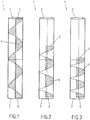
- Figures 1 to 3 depict a nozzle 1 in different states.
- the nozzle comprises a gas inlet 2 and a gas outlet 3.
- a helically shaped guiding element 4 is arranged between the gas inlet 2 and the gas outlet 3.
- the helically shaped guiding element 4 comprises a front edge 5 and a back edge 6.
- a gas (eventually comprising solid material to be transported) can be supplied through the gas inlet 2 into the nozzle 1, wherein the gas is forced by the helically shaped guiding element 4 onto a helical trajectory through the nozzle 1. Due to this helical trajectory the gas has a swirl at the gas outlet 3 when leaving the nozzle 1.
- the swirl of the gas is characterized by the swirl number.
- the front edge 5 is connected to a setting element, with which the front edge 5 can be moved towards the outlet 3 and back.
- the helically shaped guiding element 4 is compressed, so that the pitch of the helically shaped guiding element 4 is altered, thereby altering the swirl number.
- the compression of the helically shaped guiding element 4 can be set to different levels so that the swirl number can be altered continuously.
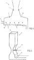
- the nozzle depicted in figures 1 to 3 can be used in an incineration plant 7 as depicted in figure 4 .
- the incineration plant 7 comprises a combustion chamber 8 with a combustion material inlet 9.
- the combustion material i.e. waste
- the combustion material can be conveyed through the combustion chamber 8 by a combustion grate 10.
- Primary air for combusting the solid material on top of the combustion grate 10 is provided from below the combustion grate 10 (not depicted).
- secondary air is supplied to the primary combustion gases through nozzles 1, which are arranged above the combustion grate 10.
- the nozzle 1 can also be used in a reactor 11 for desulfurization of flue gases by a dry or quasi-dry sorption process.
- a respective reactor 11 is depicted in figure 5 .
- the reactor 11 comprises a flue gas inlet 12 and a flue gas outlet 13, which is arranged vertically above the flue gas inlet 12.
- the flue gas inlet 12 is connected to a vertically extending supply line, through which flue gases are supplied to the reactor 11.
- a venturi section is formed between the flue gas inlet 12 and the flue gas outlet 13.
- a nozzle 1 is arranged as part of a dry sorbent injection system 14. Dry sorbent powder is provided with a carrier gas through the nozzle 1.
- the carrier gas and also the dry sorbent powder is provided into the reactor with a swirl, so that an enhanced mixture with the flue gas and therefore an enhanced sorption process occurs.
Landscapes
- Engineering & Computer Science (AREA)
- Chemical & Material Sciences (AREA)
- Mechanical Engineering (AREA)
- General Engineering & Computer Science (AREA)
- Combustion & Propulsion (AREA)
- Chemical Kinetics & Catalysis (AREA)
- General Chemical & Material Sciences (AREA)
- Treating Waste Gases (AREA)
- Fluidized-Bed Combustion And Resonant Combustion (AREA)
- Cleaning In General (AREA)
- Incineration Of Waste (AREA)
- Physical Or Chemical Processes And Apparatus (AREA)
Claims (7)
- Verbrennungsanlage (7) mit- einer Brennkammer (8),- einem Brennmaterialeinlass (9) durch den festes Material in die Brennkammer (8) eingeführt werden kann,- einem Verbrennungsrost (10), mit dem das feste Material und verbranntes festes Material durch die Brennkammer (8) befördert werden kann,- einer Primärluftzufuhr unterhalb der Oberseite des Verbrennungsrostes (10),- mindestens einer Düse (1), die oberhalb des Verbrennungsrostes (10) angeordnet ist, mit der Sekundärluft und/oder ein sauerstoffarmes Trägergas bereitgestellt werden kann, wobei die Düse (1) einen Gaseinlass (2) und einen Gasauslass (3) aufweist,dadurch gekennzeichnet, dass
ein spiralförmiges Führungselement (4) in der Düse zwischen dem Gaseinlass (2) und dem Gasauslass (3) angeordnet ist, um das Gas mit einem Wirbel zu beaufschlagen, wobei das spiralförmige Führungselement (4) eine Vorderkante (5) und eine Hinterkante (6) aufweist, wobei die Vorderkante (5) und die Hinterkante (6) in Längsrichtung der Düse (1) in einem Abstand zueinander versetzt sind. - Reaktor (11) zum Reinigen von Abgasen durch ein trockenes oder quasi-trockenes Sorptionsverfahren, umfassend- einen Abgaseinlass (12) am Boden des Reaktors (11),- einen Auslass (13) am oberen Ende des Reaktors (11),- ein Trockensorptionsmittel-Injektionssystem (14) mit mindestens einer Trockensorptionsmitteldüse (1) zum Injizieren von Trockensorptionsmittel mit einem Trägergas in den Reaktor (11), wobei die mindestens eine Düse (1) zwischen dem Abgaseinlass (12) und dem Auslass (13) angeordnet ist,- wobei die mindestens eine Düse (1) einen Gaseinlass (2) und einen Gasauslass (3) aufweist,dadurch gekennzeichnet, dass
ein spiralförmiges Führungselement (4) in der Düse zwischen dem Gaseinlass (2) und dem Gasauslass (3) angeordnet ist, um das Trockensorptionsmittel, das Trägergas umfasst, mit einem Wirbel zu beaufschlagen, wobei das spiralförmige Führungselement (4) eine Vorderkante (5) und eine Hinterkante (6) aufweist, wobei die Vorderkante (5) und die Hinterkante (6) in Längsrichtung der Düse (1) in einem Abstand zueinander versetzt sind. - Verbrennungsanlage (7) nach Anspruch 1 oder Reaktor (11) nach Anspruch 2, dadurch gekennzeichnet, dass das spiralförmige Führungselement (4) flexibel ist, und dadurch, dass die Düse (1) ein Einstellelement aufweist, das ausgebildet ist, um den Abstand zwischen der Vorderkante (5) und der Hinterkante (6) des spiralförmig geformten Führungselements (4) zu verändern.
- Verbrennungsanlage (7) oder Reaktor (11) nach einem der jeweiligen vorhergehenden Ansprüche, wobei das spiralförmige Führungselement (4) aus einem elastischen Material oder aus einer elastisch verformbaren Platte hergestellt ist.
- Verbrennungsanlage (7) oder Reaktor (11) nach Anspruch 3 oder 4, wobei die Vorderseite oder Rückseite des spiralförmigen Führungselementes (4) ortsfest und die Rückseite oder die Vorderseite an dem in Längsrichtung verschiebbaren Einstellelement befestigt ist.
- Verbrennungsanlage (7) oder Reaktor (11) nach Anspruch 3 bis 5, wobei das Einstellelement manuell oder durch ein elektronisch steuerbares Stellglied zu betätigen ist.
- Verbrennungsanlage (7) oder Reaktor (11) nach einem der vorhergehenden Ansprüche, wobei die Düse (1) einen zentralen Strömungskanal und einen den zentralen Strömungskanal umgebenden äußeren Strömungskanal aufweist, wobei in dem zentralen Strömungskanal und/oder in dem äußeren Strömungskanal ein spiralförmiges Führungselement (4) angeordnet ist.
Priority Applications (10)
| Application Number | Priority Date | Filing Date | Title |
|---|---|---|---|
| EP18211081.7A EP3663647B1 (de) | 2018-12-07 | 2018-12-07 | Verbrennungsanlage mit einer düse, reaktor zur reinigung von abgasen mit einer düse |
| PL18211081T PL3663647T3 (pl) | 2018-12-07 | 2018-12-07 | Instalacja do spopielania z dyszą, reaktor do oczyszczania gazów spalinowych z dyszą |
| LTEP18211081.7T LT3663647T (lt) | 2018-12-07 | 2018-12-07 | Deginimo įranga su purkštuku, reaktorius dujų valymui su purkštuku |
| PT182110817T PT3663647T (pt) | 2018-12-07 | 2018-12-07 | Instalação de incineração com um bocal e reator para limpeza de efluentes gasosos com um bocal |
| RS20210234A RS61512B1 (sr) | 2018-12-07 | 2018-12-07 | Postrojenje za spaljivanje sa mlaznicom, reaktor za prečišćavanje dimnih gasova sa mlaznicom |
| HUE18211081A HUE053461T2 (hu) | 2018-12-07 | 2018-12-07 | Égetõ berendezés fúvókával, reaktor füstgázok tisztítására fúvókával |
| ES18211081T ES2854275T3 (es) | 2018-12-07 | 2018-12-07 | Planta de incineración con boquilla y reactor para la limpieza de efluentes gaseosos con boquilla |
| SI201830214T SI3663647T1 (sl) | 2018-12-07 | 2018-12-07 | Sežigalna naprava s šobo, reaktor za čiščenje dimnih plinov s šobo |
| PCT/EP2019/082495 WO2020114826A1 (en) | 2018-12-07 | 2019-11-26 | Incineration plant with a nozzle and reactor for cleaning flue gases with a nozzle |
| HRP20210275TT HRP20210275T1 (hr) | 2018-12-07 | 2021-02-17 | Postrojenje za spaljivanje s diznom, reaktor za pročišćavanje dimnih plinova s diznom |
Applications Claiming Priority (1)
| Application Number | Priority Date | Filing Date | Title |
|---|---|---|---|
| EP18211081.7A EP3663647B1 (de) | 2018-12-07 | 2018-12-07 | Verbrennungsanlage mit einer düse, reaktor zur reinigung von abgasen mit einer düse |
Publications (2)
| Publication Number | Publication Date |
|---|---|
| EP3663647A1 EP3663647A1 (de) | 2020-06-10 |
| EP3663647B1 true EP3663647B1 (de) | 2020-12-30 |
Family
ID=64661199
Family Applications (1)
| Application Number | Title | Priority Date | Filing Date |
|---|---|---|---|
| EP18211081.7A Active EP3663647B1 (de) | 2018-12-07 | 2018-12-07 | Verbrennungsanlage mit einer düse, reaktor zur reinigung von abgasen mit einer düse |
Country Status (10)
| Country | Link |
|---|---|
| EP (1) | EP3663647B1 (de) |
| ES (1) | ES2854275T3 (de) |
| HR (1) | HRP20210275T1 (de) |
| HU (1) | HUE053461T2 (de) |
| LT (1) | LT3663647T (de) |
| PL (1) | PL3663647T3 (de) |
| PT (1) | PT3663647T (de) |
| RS (1) | RS61512B1 (de) |
| SI (1) | SI3663647T1 (de) |
| WO (1) | WO2020114826A1 (de) |
Families Citing this family (1)
| Publication number | Priority date | Publication date | Assignee | Title |
|---|---|---|---|---|
| DE102021002508A1 (de) | 2021-05-12 | 2022-11-17 | Martin GmbH für Umwelt- und Energietechnik | Düse zum Einblasen von Gas in eine Verbrennungsanlage mit einem Rohr und einem Drallerzeuger, Rauchgaszug mit einer derartigen Düse und Verfahren zur Verwendung einer derartigen Düse |
Family Cites Families (8)
| Publication number | Priority date | Publication date | Assignee | Title |
|---|---|---|---|---|
| US2613481A (en) * | 1947-08-01 | 1952-10-14 | Nat Cylinder Gas Co | Pressure regulating valve |
| US5011400A (en) * | 1986-02-03 | 1991-04-30 | Foster Wheeler Energy Corporation | Controlled flow split steam burner assembly with sorbent injection |
| FR2683744B1 (fr) * | 1991-11-19 | 1995-01-13 | Institut Francais Petrole | Tete d'injection destinee a ameliorer la dispersion d'une poudre dans une chambre de desulfuration d'un generateur de chaleur. |
| US5503089A (en) * | 1992-12-29 | 1996-04-02 | Finmeccanica S.P.A. - Azienda Ansaldo | Arrangement for hot killing the acids contained in flue gases from waste disposal plants, power plants, and industrial production plants |
| GB9917637D0 (en) * | 1999-07-27 | 1999-09-29 | Co Ordinated Drug Dev | Improvements in or relating to inhaler devices |
| DE102004037442B4 (de) | 2004-08-02 | 2007-07-12 | Ae&E Inova Gmbh | Verfahren zur thermischen Behandlung von Abfall in einer thermischen Abfallbehandlungsanlage sowie thermische Abfallbehandlungsanlage |
| CN101402019B (zh) | 2008-11-06 | 2012-12-26 | 北京博朗环境工程技术股份有限公司 | 均流场内回流循环流化床烟气脱硫反应器 |
| US10473400B2 (en) * | 2013-10-17 | 2019-11-12 | Hatch Pty Ltd. | Dispersion apparatus |
-
2018
- 2018-12-07 RS RS20210234A patent/RS61512B1/sr unknown
- 2018-12-07 LT LTEP18211081.7T patent/LT3663647T/lt unknown
- 2018-12-07 ES ES18211081T patent/ES2854275T3/es active Active
- 2018-12-07 PL PL18211081T patent/PL3663647T3/pl unknown
- 2018-12-07 SI SI201830214T patent/SI3663647T1/sl unknown
- 2018-12-07 HU HUE18211081A patent/HUE053461T2/hu unknown
- 2018-12-07 PT PT182110817T patent/PT3663647T/pt unknown
- 2018-12-07 EP EP18211081.7A patent/EP3663647B1/de active Active
-
2019
- 2019-11-26 WO PCT/EP2019/082495 patent/WO2020114826A1/en not_active Ceased
-
2021
- 2021-02-17 HR HRP20210275TT patent/HRP20210275T1/hr unknown
Non-Patent Citations (1)
| Title |
|---|
| None * |
Also Published As
| Publication number | Publication date |
|---|---|
| RS61512B1 (sr) | 2021-03-31 |
| HRP20210275T1 (hr) | 2021-04-02 |
| EP3663647A1 (de) | 2020-06-10 |
| HUE053461T2 (hu) | 2021-06-28 |
| PL3663647T3 (pl) | 2021-06-14 |
| LT3663647T (lt) | 2021-02-25 |
| WO2020114826A1 (en) | 2020-06-11 |
| SI3663647T1 (sl) | 2021-03-31 |
| ES2854275T3 (es) | 2021-09-21 |
| PT3663647T (pt) | 2021-02-18 |
Similar Documents
| Publication | Publication Date | Title |
|---|---|---|
| EP3322507B1 (de) | Verfahren zur reduzierung des schwefeldioxidgehalts in rauchgas, das aus einer kesselanlage mit zirkulierender wirbelschicht ausströmt | |
| DE112008001319T5 (de) | Staubkohlenkessel, Staubkohle-Verbrennungsverfahren, Staubkohlenbrennstoff-Wärmeleistungserzeugungssystem und Abgasreinigungssystem für Staubkohlenkessel | |
| AT515897B1 (de) | Heizkessel | |
| EP3663647B1 (de) | Verbrennungsanlage mit einer düse, reaktor zur reinigung von abgasen mit einer düse | |
| KR940006634A (ko) | 연소공정에서 황산화물 방출을 감소시키기 위한 방법 및 그 반응기 | |
| US9040004B2 (en) | Method and device for cleaning exhaust gases by way of fluidized bed reactors | |
| US5194076A (en) | Low pressure drop dry scrubber | |
| CN101385941A (zh) | 高效循环流化床烟气脱硫装置 | |
| KR20000023215A (ko) | 연도가스로부터 산화질소를 제거하는 방법 | |
| US20050084437A1 (en) | Scrubbing systems and methods for coal fired combustion units | |
| TW202045239A (zh) | 於煙道氣導管中分散吸收粒子之裝置及方法 | |
| US5396849A (en) | Combustion method producing low levels of pollutants and apparatus for same | |
| AT394660B (de) | Verfahren zur entfernung bzw. verminderung von gasfoermigen schadstoffen und vorrichtung zur durchfuehrung dieses verfahrens | |
| KR101224946B1 (ko) | 백하우스 및 이를 구비한 순환유동층보일러용 하이브리드 집진설비 | |
| US6817304B2 (en) | Process for generating heat to reduce the emission of oxides of sulphur and reduce adsorbent consumption | |
| WO1996009896A1 (en) | Nozzle impulse controlled vent air flow | |
| PL107437B1 (pl) | Sposob usuwania zanieczyszczen ze strumienia gazu i urzadzenie do usuwania zanieczyszczen ze strumienia gazu | |
| KR101231923B1 (ko) | 반건식 탈황장치 및 이를 구비한 순환유동층보일러용 하이브리드 집진설비 | |
| US8075858B1 (en) | Trumpet shaped element and process for minimizing solid and gaseous pollutants from waste off-gasses and liquid streams | |
| EP0734755B1 (de) | Verfahren zur Trockenentschwefelung von Rauchgasen | |
| US5643344A (en) | Dry scrubber with forced recirculation | |
| DE4139348C1 (en) | Removing sulphurous fumes from combustion gases - by mixing fuel with calcium carbonate, calcium hydroxide and calcium oxide, and spraying hot combustion gas with water | |
| CN111841242A (zh) | 一种垃圾处理用环保烟气处理装置 | |
| US5328674A (en) | Combustion gas desulfurization method | |
| CA2126508A1 (en) | High efficiency advanced dry scrubber |
Legal Events
| Date | Code | Title | Description |
|---|---|---|---|
| STAA | Information on the status of an ep patent application or granted ep patent |
Free format text: STATUS: EXAMINATION IS IN PROGRESS |
|
| PUAI | Public reference made under article 153(3) epc to a published international application that has entered the european phase |
Free format text: ORIGINAL CODE: 0009012 |
|
| 17P | Request for examination filed |
Effective date: 20190926 |
|
| AK | Designated contracting states |
Kind code of ref document: A1 Designated state(s): AL AT BE BG CH CY CZ DE DK EE ES FI FR GB GR HR HU IE IS IT LI LT LU LV MC MK MT NL NO PL PT RO RS SE SI SK SM TR |
|
| AX | Request for extension of the european patent |
Extension state: BA ME |
|
| GRAP | Despatch of communication of intention to grant a patent |
Free format text: ORIGINAL CODE: EPIDOSNIGR1 |
|
| STAA | Information on the status of an ep patent application or granted ep patent |
Free format text: STATUS: GRANT OF PATENT IS INTENDED |
|
| INTG | Intention to grant announced |
Effective date: 20200710 |
|
| GRAS | Grant fee paid |
Free format text: ORIGINAL CODE: EPIDOSNIGR3 |
|
| GRAA | (expected) grant |
Free format text: ORIGINAL CODE: 0009210 |
|
| STAA | Information on the status of an ep patent application or granted ep patent |
Free format text: STATUS: THE PATENT HAS BEEN GRANTED |
|
| AK | Designated contracting states |
Kind code of ref document: B1 Designated state(s): AL AT BE BG CH CY CZ DE DK EE ES FI FR GB GR HR HU IE IS IT LI LT LU LV MC MK MT NL NO PL PT RO RS SE SI SK SM TR |
|
| REG | Reference to a national code |
Ref country code: GB Ref legal event code: FG4D |
|
| REG | Reference to a national code |
Ref country code: DE Ref legal event code: R096 Ref document number: 602018011328 Country of ref document: DE |
|
| REG | Reference to a national code |
Ref country code: AT Ref legal event code: REF Ref document number: 1350307 Country of ref document: AT Kind code of ref document: T Effective date: 20210115 |
|
| REG | Reference to a national code |
Ref country code: IE Ref legal event code: FG4D |
|
| REG | Reference to a national code |
Ref country code: HR Ref legal event code: TUEP Ref document number: P20210275 Country of ref document: HR |
|
| REG | Reference to a national code |
Ref country code: PT Ref legal event code: SC4A Ref document number: 3663647 Country of ref document: PT Date of ref document: 20210218 Kind code of ref document: T Free format text: AVAILABILITY OF NATIONAL TRANSLATION Effective date: 20210211 Ref country code: FI Ref legal event code: FGE |
|
| REG | Reference to a national code |
Ref country code: RO Ref legal event code: EPE |
|
| REG | Reference to a national code |
Ref country code: SE Ref legal event code: TRGR |
|
| REG | Reference to a national code |
Ref country code: NL Ref legal event code: FP |
|
| REG | Reference to a national code |
Ref country code: HR Ref legal event code: T1PR Ref document number: P20210275 Country of ref document: HR |
|
| REG | Reference to a national code |
Ref country code: SK Ref legal event code: T3 Ref document number: E 36739 Country of ref document: SK |
|
| PG25 | Lapsed in a contracting state [announced via postgrant information from national office to epo] |
Ref country code: GR Free format text: LAPSE BECAUSE OF FAILURE TO SUBMIT A TRANSLATION OF THE DESCRIPTION OR TO PAY THE FEE WITHIN THE PRESCRIBED TIME-LIMIT Effective date: 20210331 Ref country code: NO Free format text: LAPSE BECAUSE OF FAILURE TO SUBMIT A TRANSLATION OF THE DESCRIPTION OR TO PAY THE FEE WITHIN THE PRESCRIBED TIME-LIMIT Effective date: 20210330 |
|
| PG25 | Lapsed in a contracting state [announced via postgrant information from national office to epo] |
Ref country code: LV Free format text: LAPSE BECAUSE OF FAILURE TO SUBMIT A TRANSLATION OF THE DESCRIPTION OR TO PAY THE FEE WITHIN THE PRESCRIBED TIME-LIMIT Effective date: 20201230 |
|
| REG | Reference to a national code |
Ref country code: HU Ref legal event code: AG4A Ref document number: E053461 Country of ref document: HU |
|
| PG25 | Lapsed in a contracting state [announced via postgrant information from national office to epo] |
Ref country code: EE Free format text: LAPSE BECAUSE OF FAILURE TO SUBMIT A TRANSLATION OF THE DESCRIPTION OR TO PAY THE FEE WITHIN THE PRESCRIBED TIME-LIMIT Effective date: 20201230 |
|
| REG | Reference to a national code |
Ref country code: ES Ref legal event code: FG2A Ref document number: 2854275 Country of ref document: ES Kind code of ref document: T3 Effective date: 20210921 |
|
| PG25 | Lapsed in a contracting state [announced via postgrant information from national office to epo] |
Ref country code: IS Free format text: LAPSE BECAUSE OF FAILURE TO SUBMIT A TRANSLATION OF THE DESCRIPTION OR TO PAY THE FEE WITHIN THE PRESCRIBED TIME-LIMIT Effective date: 20210430 |
|
| REG | Reference to a national code |
Ref country code: DE Ref legal event code: R097 Ref document number: 602018011328 Country of ref document: DE |
|
| PG25 | Lapsed in a contracting state [announced via postgrant information from national office to epo] |
Ref country code: AL Free format text: LAPSE BECAUSE OF FAILURE TO SUBMIT A TRANSLATION OF THE DESCRIPTION OR TO PAY THE FEE WITHIN THE PRESCRIBED TIME-LIMIT Effective date: 20201230 Ref country code: IT Free format text: LAPSE BECAUSE OF FAILURE TO SUBMIT A TRANSLATION OF THE DESCRIPTION OR TO PAY THE FEE WITHIN THE PRESCRIBED TIME-LIMIT Effective date: 20201230 |
|
| PLBE | No opposition filed within time limit |
Free format text: ORIGINAL CODE: 0009261 |
|
| STAA | Information on the status of an ep patent application or granted ep patent |
Free format text: STATUS: NO OPPOSITION FILED WITHIN TIME LIMIT |
|
| PG25 | Lapsed in a contracting state [announced via postgrant information from national office to epo] |
Ref country code: DK Free format text: LAPSE BECAUSE OF FAILURE TO SUBMIT A TRANSLATION OF THE DESCRIPTION OR TO PAY THE FEE WITHIN THE PRESCRIBED TIME-LIMIT Effective date: 20201230 |
|
| 26N | No opposition filed |
Effective date: 20211001 |
|
| REG | Reference to a national code |
Ref country code: HR Ref legal event code: ODRP Ref document number: P20210275 Country of ref document: HR Payment date: 20211129 Year of fee payment: 4 |
|
| PGFP | Annual fee paid to national office [announced via postgrant information from national office to epo] |
Ref country code: SK Payment date: 20211201 Year of fee payment: 4 Ref country code: RS Payment date: 20211203 Year of fee payment: 4 Ref country code: RO Payment date: 20211202 Year of fee payment: 4 Ref country code: TR Payment date: 20211130 Year of fee payment: 4 Ref country code: SE Payment date: 20211220 Year of fee payment: 4 Ref country code: CZ Payment date: 20211126 Year of fee payment: 4 Ref country code: BG Payment date: 20211216 Year of fee payment: 4 Ref country code: DE Payment date: 20211115 Year of fee payment: 4 Ref country code: FR Payment date: 20211220 Year of fee payment: 4 Ref country code: FI Payment date: 20211216 Year of fee payment: 4 Ref country code: IE Payment date: 20211220 Year of fee payment: 4 Ref country code: LT Payment date: 20211123 Year of fee payment: 4 Ref country code: HR Payment date: 20211129 Year of fee payment: 4 |
|
| PGFP | Annual fee paid to national office [announced via postgrant information from national office to epo] |
Ref country code: SI Payment date: 20211125 Year of fee payment: 4 Ref country code: HU Payment date: 20211128 Year of fee payment: 4 Ref country code: CH Payment date: 20211222 Year of fee payment: 4 Ref country code: BE Payment date: 20211217 Year of fee payment: 4 |
|
| PGFP | Annual fee paid to national office [announced via postgrant information from national office to epo] |
Ref country code: PL Payment date: 20211125 Year of fee payment: 4 Ref country code: NL Payment date: 20211217 Year of fee payment: 4 |
|
| PG25 | Lapsed in a contracting state [announced via postgrant information from national office to epo] |
Ref country code: IS Free format text: LAPSE BECAUSE OF FAILURE TO SUBMIT A TRANSLATION OF THE DESCRIPTION OR TO PAY THE FEE WITHIN THE PRESCRIBED TIME-LIMIT Effective date: 20210430 |
|
| PGFP | Annual fee paid to national office [announced via postgrant information from national office to epo] |
Ref country code: ES Payment date: 20220119 Year of fee payment: 4 |
|
| PG25 | Lapsed in a contracting state [announced via postgrant information from national office to epo] |
Ref country code: MC Free format text: LAPSE BECAUSE OF FAILURE TO SUBMIT A TRANSLATION OF THE DESCRIPTION OR TO PAY THE FEE WITHIN THE PRESCRIBED TIME-LIMIT Effective date: 20201230 |
|
| PG25 | Lapsed in a contracting state [announced via postgrant information from national office to epo] |
Ref country code: LU Free format text: LAPSE BECAUSE OF NON-PAYMENT OF DUE FEES Effective date: 20211207 |
|
| REG | Reference to a national code |
Ref country code: HR Ref legal event code: PBON Ref document number: P20210275 Country of ref document: HR Effective date: 20221207 |
|
| REG | Reference to a national code |
Ref country code: LT Ref legal event code: MM4D Effective date: 20221207 |
|
| PG25 | Lapsed in a contracting state [announced via postgrant information from national office to epo] |
Ref country code: CY Free format text: LAPSE BECAUSE OF FAILURE TO SUBMIT A TRANSLATION OF THE DESCRIPTION OR TO PAY THE FEE WITHIN THE PRESCRIBED TIME-LIMIT Effective date: 20201230 |
|
| REG | Reference to a national code |
Ref country code: DE Ref legal event code: R119 Ref document number: 602018011328 Country of ref document: DE |
|
| REG | Reference to a national code |
Ref country code: SK Ref legal event code: MM4A Ref document number: E 36739 Country of ref document: SK Effective date: 20221207 |
|
| PG25 | Lapsed in a contracting state [announced via postgrant information from national office to epo] |
Ref country code: SM Free format text: LAPSE BECAUSE OF FAILURE TO SUBMIT A TRANSLATION OF THE DESCRIPTION OR TO PAY THE FEE WITHIN THE PRESCRIBED TIME-LIMIT Effective date: 20201230 Ref country code: RS Free format text: LAPSE BECAUSE OF NON-PAYMENT OF DUE FEES Effective date: 20221207 Ref country code: RO Free format text: LAPSE BECAUSE OF NON-PAYMENT OF DUE FEES Effective date: 20221207 Ref country code: PT Free format text: LAPSE BECAUSE OF NON-PAYMENT OF DUE FEES Effective date: 20230607 Ref country code: LT Free format text: LAPSE BECAUSE OF NON-PAYMENT OF DUE FEES Effective date: 20221207 Ref country code: CZ Free format text: LAPSE BECAUSE OF NON-PAYMENT OF DUE FEES Effective date: 20221207 |
|
| REG | Reference to a national code |
Ref country code: CH Ref legal event code: PL |
|
| REG | Reference to a national code |
Ref country code: SE Ref legal event code: EUG |
|
| REG | Reference to a national code |
Ref country code: NL Ref legal event code: MM Effective date: 20230101 |
|
| GBPC | Gb: european patent ceased through non-payment of renewal fee |
Effective date: 20221207 |
|
| REG | Reference to a national code |
Ref country code: BE Ref legal event code: MM Effective date: 20221231 |
|
| PG25 | Lapsed in a contracting state [announced via postgrant information from national office to epo] |
Ref country code: NL Free format text: LAPSE BECAUSE OF NON-PAYMENT OF DUE FEES Effective date: 20230101 |
|
| REG | Reference to a national code |
Ref country code: SI Ref legal event code: KO00 Effective date: 20230810 |
|
| PG25 | Lapsed in a contracting state [announced via postgrant information from national office to epo] |
Ref country code: SE Free format text: LAPSE BECAUSE OF NON-PAYMENT OF DUE FEES Effective date: 20221208 Ref country code: LI Free format text: LAPSE BECAUSE OF NON-PAYMENT OF DUE FEES Effective date: 20221231 Ref country code: IE Free format text: LAPSE BECAUSE OF NON-PAYMENT OF DUE FEES Effective date: 20221207 Ref country code: GB Free format text: LAPSE BECAUSE OF NON-PAYMENT OF DUE FEES Effective date: 20221207 Ref country code: DE Free format text: LAPSE BECAUSE OF NON-PAYMENT OF DUE FEES Effective date: 20230701 Ref country code: CH Free format text: LAPSE BECAUSE OF NON-PAYMENT OF DUE FEES Effective date: 20221231 |
|
| PG25 | Lapsed in a contracting state [announced via postgrant information from national office to epo] |
Ref country code: SK Free format text: LAPSE BECAUSE OF NON-PAYMENT OF DUE FEES Effective date: 20221207 Ref country code: SI Free format text: LAPSE BECAUSE OF NON-PAYMENT OF DUE FEES Effective date: 20221208 Ref country code: HU Free format text: LAPSE BECAUSE OF NON-PAYMENT OF DUE FEES Effective date: 20221208 Ref country code: HR Free format text: LAPSE BECAUSE OF NON-PAYMENT OF DUE FEES Effective date: 20221207 Ref country code: FR Free format text: LAPSE BECAUSE OF NON-PAYMENT OF DUE FEES Effective date: 20221231 Ref country code: BE Free format text: LAPSE BECAUSE OF NON-PAYMENT OF DUE FEES Effective date: 20221231 |
|
| REG | Reference to a national code |
Ref country code: ES Ref legal event code: FD2A Effective date: 20240126 |
|
| PG25 | Lapsed in a contracting state [announced via postgrant information from national office to epo] |
Ref country code: ES Free format text: LAPSE BECAUSE OF NON-PAYMENT OF DUE FEES Effective date: 20221208 |
|
| PG25 | Lapsed in a contracting state [announced via postgrant information from national office to epo] |
Ref country code: MK Free format text: LAPSE BECAUSE OF FAILURE TO SUBMIT A TRANSLATION OF THE DESCRIPTION OR TO PAY THE FEE WITHIN THE PRESCRIBED TIME-LIMIT Effective date: 20201230 Ref country code: FI Free format text: LAPSE BECAUSE OF NON-PAYMENT OF DUE FEES Effective date: 20221207 Ref country code: ES Free format text: LAPSE BECAUSE OF NON-PAYMENT OF DUE FEES Effective date: 20221208 |
|
| PG25 | Lapsed in a contracting state [announced via postgrant information from national office to epo] |
Ref country code: PL Free format text: LAPSE BECAUSE OF NON-PAYMENT OF DUE FEES Effective date: 20221207 |
|
| PG25 | Lapsed in a contracting state [announced via postgrant information from national office to epo] |
Ref country code: BG Free format text: LAPSE BECAUSE OF NON-PAYMENT OF DUE FEES Effective date: 20221207 |
|
| PG25 | Lapsed in a contracting state [announced via postgrant information from national office to epo] |
Ref country code: MT Free format text: LAPSE BECAUSE OF FAILURE TO SUBMIT A TRANSLATION OF THE DESCRIPTION OR TO PAY THE FEE WITHIN THE PRESCRIBED TIME-LIMIT Effective date: 20201230 |
|
| REG | Reference to a national code |
Ref country code: AT Ref legal event code: MM01 Ref document number: 1350307 Country of ref document: AT Kind code of ref document: T Effective date: 20231207 |
|
| PG25 | Lapsed in a contracting state [announced via postgrant information from national office to epo] |
Ref country code: AT Free format text: LAPSE BECAUSE OF NON-PAYMENT OF DUE FEES Effective date: 20231207 |
|
| REG | Reference to a national code |
Ref country code: AT Ref legal event code: UEP Ref document number: 1350307 Country of ref document: AT Kind code of ref document: T Effective date: 20201230 |
|
| PGFP | Annual fee paid to national office [announced via postgrant information from national office to epo] |
Ref country code: AT Payment date: 20260410 Year of fee payment: 5 |