EP3663625A1 - Vorrichtung und verfahren zum verbinden eines ersten elektrisch leitenden rohrs und eines zweiten elektrisch leitenden rohrs - Google Patents
Vorrichtung und verfahren zum verbinden eines ersten elektrisch leitenden rohrs und eines zweiten elektrisch leitenden rohrs Download PDFInfo
- Publication number
- EP3663625A1 EP3663625A1 EP19210686.2A EP19210686A EP3663625A1 EP 3663625 A1 EP3663625 A1 EP 3663625A1 EP 19210686 A EP19210686 A EP 19210686A EP 3663625 A1 EP3663625 A1 EP 3663625A1
- Authority
- EP
- European Patent Office
- Prior art keywords
- electrically conductive
- conductive tube
- electrical isolator
- nut
- sealing component
- Prior art date
- Legal status (The legal status is an assumption and is not a legal conclusion. Google has not performed a legal analysis and makes no representation as to the accuracy of the status listed.)
- Granted
Links
Images




Classifications
-
- F—MECHANICAL ENGINEERING; LIGHTING; HEATING; WEAPONS; BLASTING
- F16—ENGINEERING ELEMENTS AND UNITS; GENERAL MEASURES FOR PRODUCING AND MAINTAINING EFFECTIVE FUNCTIONING OF MACHINES OR INSTALLATIONS; THERMAL INSULATION IN GENERAL
- F16L—PIPES; JOINTS OR FITTINGS FOR PIPES; SUPPORTS FOR PIPES, CABLES OR PROTECTIVE TUBING; MEANS FOR THERMAL INSULATION IN GENERAL
- F16L25/00—Construction or details of pipe joints not provided for in, or of interest apart from, groups F16L13/00 - F16L23/00
- F16L25/02—Construction or details of pipe joints not provided for in, or of interest apart from, groups F16L13/00 - F16L23/00 specially adapted for electrically insulating the two pipe ends of the joint from each other
- F16L25/025—Construction or details of pipe joints not provided for in, or of interest apart from, groups F16L13/00 - F16L23/00 specially adapted for electrically insulating the two pipe ends of the joint from each other for joints with sleeve or socket
-
- F—MECHANICAL ENGINEERING; LIGHTING; HEATING; WEAPONS; BLASTING
- F16—ENGINEERING ELEMENTS AND UNITS; GENERAL MEASURES FOR PRODUCING AND MAINTAINING EFFECTIVE FUNCTIONING OF MACHINES OR INSTALLATIONS; THERMAL INSULATION IN GENERAL
- F16L—PIPES; JOINTS OR FITTINGS FOR PIPES; SUPPORTS FOR PIPES, CABLES OR PROTECTIVE TUBING; MEANS FOR THERMAL INSULATION IN GENERAL
- F16L25/00—Construction or details of pipe joints not provided for in, or of interest apart from, groups F16L13/00 - F16L23/00
- F16L25/02—Construction or details of pipe joints not provided for in, or of interest apart from, groups F16L13/00 - F16L23/00 specially adapted for electrically insulating the two pipe ends of the joint from each other
- F16L25/021—Construction or details of pipe joints not provided for in, or of interest apart from, groups F16L13/00 - F16L23/00 specially adapted for electrically insulating the two pipe ends of the joint from each other for screw-threaded joints
-
- F—MECHANICAL ENGINEERING; LIGHTING; HEATING; WEAPONS; BLASTING
- F16—ENGINEERING ELEMENTS AND UNITS; GENERAL MEASURES FOR PRODUCING AND MAINTAINING EFFECTIVE FUNCTIONING OF MACHINES OR INSTALLATIONS; THERMAL INSULATION IN GENERAL
- F16L—PIPES; JOINTS OR FITTINGS FOR PIPES; SUPPORTS FOR PIPES, CABLES OR PROTECTIVE TUBING; MEANS FOR THERMAL INSULATION IN GENERAL
- F16L25/00—Construction or details of pipe joints not provided for in, or of interest apart from, groups F16L13/00 - F16L23/00
- F16L25/02—Construction or details of pipe joints not provided for in, or of interest apart from, groups F16L13/00 - F16L23/00 specially adapted for electrically insulating the two pipe ends of the joint from each other
- F16L25/023—Construction or details of pipe joints not provided for in, or of interest apart from, groups F16L13/00 - F16L23/00 specially adapted for electrically insulating the two pipe ends of the joint from each other for joints in which sealing surfaces are pressed together by means of a member, e.g. a swivel nut, screwed on or into one of the joint parts
Definitions
- the present application relates to the field of connections for connecting electrically conductive tubular components, particular connections for connecting and electrically isolating electrically conductive tubular components.
- electrostatic charge may build up on an electrically conductive tubular component.
- an electromagnetic event may cause electrical current to flow in an electrically conductive tubular component. Therefore, in some situations it is desirable to electrically isolate the connected electrically conductive tubular components to protect from electrostatic charge transfer or electrical current transfer between the connected electrically conductive tubular components.
- a method for connecting a first electrically conductive tube and a second electrically conductive tube includes inserting a first electrical isolator into a flared end of the first electrically conductive tube, the first electrical isolator having a central passageway. The method further includes positioning a second electrical isolator around the second electrically conductive tube such that the second electrical isolator engages an outer flange of the second electrically conductive tube. The method further includes positioning a nut disposed around the second electrically conductive tube and engaging the second electrical isolator. The method further includes threading the nut onto the flared end of the first electrically conductive tube.
- a method for connecting a first electrically conductive tube and a second electrically conductive tube includes electrically isolating the first electrically conductive tube and the second electrically conductive tube by positioning at least a first electrical isolator between the first electrically conductive tube and the second electrically conductive tube, the first electrical isolator having a central passageway.
- the method further includes positioning a first annular sealing component between the first electrical isolator and the first electrically conductive tube.
- the method further includes positioning a second annular sealing component between the first electrical isolator and the second electrically conductive tube.
- the method further includes energizing the first annular sealing component and the second annular sealing component by axially compressing together the first electrically conductive tube and the second electrically conductive tube.
- Figs. 1-9 illustrate an exemplary apparatus 10 of the present description. It will be understood that the present description is not limited to the details as illustrated and described.
- Fig. 1 illustrates an exploded perspective view of an exemplary apparatus 10 of the present description.
- the apparatus 10 includes a first electrically conductive tube 100, a second electrically conductive tube 200, a first electrical isolator 300, a second electrical isolator 400, and a nut 500.
- the apparatus 10 optionally further includes a first annular sealing component 600, a second annular sealing component 700, or both the first annular sealing component 600 and the second annular sealing component 700.
- the first electrically conductive tube 100 further includes a first electrically conductive tube outer surface 104.
- the first electrically conductive tube outer surface 104 defines an outer circumference of the first electrically conductive tube 100 along axis 12.
- the first electrically conductive tube 100 includes a first tubular section 106 and a flared end 108.
- the first tubular section 106 extends uniformly or substantially uniformly along axis 12.
- the first tubular section 106 defines a first tubular section inner diameter D2 and a first tubular section outer diameter D4.
- the flared end 108 includes a third flared portion 122 extending towards the first axial direction 14.
- the third flared portion 122 includes a third flared portion inner surface 124 facing radially inwardly and a third flared portion outer surface 126 facing radially outwardly.
- the third flared portion inner surface 124 defines a third flared portion inner diameter D6.
- the third flared portion outer surface 126 defines a third flared portion outer diameter D8.
- the third flared portion outer surface 126 includes external threads 128.
- the flared end 108 further includes a first torquing component 130, such as wrench flats.
- the second electrically conductive tube 200 further includes a second electrically conductive tube outer surface 204.
- the second electrically conductive tube outer surface 204 defines an outer circumference of the second electrically conductive tube 200 along axis 12.
- the second electrically conductive tube 200 includes a second tubular section 206 and an outer flange 208.
- the second tubular section 206 extends uniformly or substantially uniformly along axis 12.
- the second tubular section 206 defines a second tubular section inner diameter D10 and a second tubular section outer diameter D12.
- the second tubular section inner diameter D10 corresponds in size to the first tubular section inner diameter D2.
- the second tubular section outer diameter D12 corresponds in size to the first tubular section outer diameter D4.
- the outer flange 208 is positioned at an end the second tubular section 206 facing the second axial direction 16.
- the outer flange 208 extends radially outwardly from the second tubular section 206.
- the outer flange 208 includes an outer flange side surface 210 facing the second axial direction 16.
- the outer flange 208 includes an outer flange outer surface 212 facing the first axial direction 14 and radially outwardly.
- the outer flange 208 defines an outer flange diameter D14.
- Fig. 4A illustrates a left side view of the first electrical isolator 300 of Fig. 1 .
- Fig. 4B illustrates a right side view of the first electrical isolator 300 of Fig. 4A.
- Fig. 4C illustrates a front view of the first electrical isolator 300.
- Fig. 4D is a front sectional view of the first electrical isolator 300 along sectional line 4-4 of Fig. 4A .
- the first electrical isolator 300 includes a first electrical isolator inner surface 302 facing radially inwardly.
- the first electrical isolator inner surface 302 defines a central passageway 304 through the first electrical isolator 300.
- the first electrical isolator inner surface 302 defines a first electrical isolator inner diameter D16.
- the first electrical isolator inner diameter D16 corresponds in size to the first tubular section inner diameter D2 and the second tubular section inner diameter D10 to define an inner diameter of the apparatus 10.
- the first electrical isolator 300 further includes a first electrical isolator outer surface 306 facing radially outwardly.
- the first electrical isolator outer surface 306 defines a first electrical isolator outer diameter D18.
- the first electrical isolator outer diameter D18 corresponds in size to the third flared portion inner diameter D6.
- the first electrical isolator outer surface 306 is configured to engage with the third flared portion inner surface 124 of the flared end 108 of the first electrically conductive tube 100.
- the first electrical isolator 300 further includes a first electrical isolator outer major side surface 308 facing the first axial direction 14 and radially inwardly and a first electrical isolator inner major side surface 309 facing the first axial direction 14.
- the first electrical isolator inner major side surface 309 is configured to engage with the outer flange side surface 210 of the outer flange 208 of the second electrically conductive tube 200.
- the first electrical isolator 300 further includes a first electrical isolator minor side surface 310 facing the second axial direction 16.
- the first electrical isolator minor side surface 310 is configured to engage the first flared portion inner surface 112.
- the first electrical isolator 300 further includes a first electrical isolator inclined surface 312 facing the second axial direction 16 and radially outwardly.
- the first electrical isolator inclined surface 312 is configured to engage the second flared portion inner surface 118.
- the first electrical isolator 300 further includes a first annular groove 314 disposed in the first electrical isolator minor side surface 310 around the central passageway 304.
- the first electrical isolator 300 further includes a second annular groove 316 disposed in the first electrical isolator inner major side surface 309 around the central passageway 304.
- the first electrical isolator 300 has a minimum length represented by L4 shown as the distance between the first annular groove 314 and the second annular groove 316.
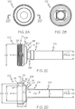
- Fig. 5A illustrates a left side view of the second electrical isolator 400 of Fig. 1 .
- Fig. 5B illustrates a right side view of the second electrical isolator 400 of Fig. 5A.
- Fig. 5C illustrates a front view of the second electrical isolator 400.
- Fig. 5D is a front sectional view of the second electrical isolator 400 along sectional line 5-5 of Fig. 5A .
- the second electrical isolator 400 includes a second electrical isolator inner surface 402 facing radially inwardly and defining a second electrical isolator inner diameter D20.
- the second electrical isolator inner diameter D20 corresponds in size to the second tubular section outer diameter D12 of the second tubular section 206 of the second electrically conductive tube 200.
- the second electrical isolator inner surface 402 is configured to engage with the second electrically conductive tube outer surface 204 of the second tubular section 206 of the second electrically conductive tube 200.
- the second electrical isolator 400 further includes a second electrical isolator outer surface 404 facing radially outwardly and defining a second electrical isolator outer diameter D22.
- the second electrical isolator outer diameter D22 corresponds in size to the first electrical isolator outer diameter D18 and the third flared portion inner diameter D6.
- the second electrical isolator outer surface 404 is configured to engage the third flared portion inner surface 124.
- the second electrical isolator 400 further includes a second electrical isolator outer major side surface 406 facing the second axial direction 16 and radially outwardly.
- the second electrical isolator outer major side surface 406 is configured to engage the first electrical isolator outer major side surface 308.
- the second electrical isolator 400 further includes a second electrical isolator inner major side surface 408 facing the second axial direction 16 and radially inwardly and a second electrical isolator outer minor side surface 410 facing the first axial direction 14 and radially outwardly.
- the second electrical isolator inner major side surface 408 is configured to engage the outer flange outer surface 212 of the outer flange 208 of the second electrically conductive tube 200.
- the second electrical isolator 400 further includes a second electrical isolator inner minor side surface 412 facing the first axial direction 14.
- the second electrical isolator 400 has a minimum width W2 represented by the width of the second electrical isolator inner minor side surface 412.
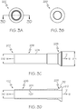
- Fig. 6A illustrates a left side view of the nut 500 of Fig. 1 .
- Fig. 6B illustrates a right side view of the nut 500 of Fig. 6A.
- Fig. 6C illustrates a front view of the nut 500.
- Fig. 6D is a front sectional view of the nut 500 along sectional line 6-6 of Fig. 6A .
- the nut 500 as shown, includes a nut inner surface 502, a nut outer surface 504, a nut front side 506, and a nut rear side 508.
- the nut 500 further includes internal threads 510.
- the internal threads 510 define a nut internal diameter D24.
- the nut internal diameter D24 corresponds to the third flared portion outer diameter D8 of the flared end 108 of the first electrically conductive tube 100.
- the nut 500 further includes a secondary retention feature in the form of a deformable rim 514.
- the deformable rim 514 is configured to deform into engagement with the secondary retention notches 121 of the second flared portion outer surface 120.
- the nut 500 further includes a second torquing component 530, such as wrench flats.
- the first torquing component 130 and the second torquing component 530 are configured to facilitate threading of the internal threads 510 of the nut 500 with the external threads 128 of the first electrically conductive tube 100.
- first annular sealing component 600 is illustrated as O-ring that can be inserted into the first annular groove 314, and the second annular sealing component 700 is illustrated as O-ring that can be inserted into the second annular groove 316.
- first annular sealing component 600 and the second annular sealing component 700 are not limited to an O-ring.
- the first annular groove 314 could be formed in the first electrically conductive tube 100
- the second annular groove 316 could be formed in the second electrically conductive tube 200
- both the first annular groove 314 and the second annular groove 316 could be formed in the first electrically conductive tube 100 and second electrically conductive tube 200, respectively.
- a liquid sealing material could be injected into the first annular groove 314, the second annular groove 316, or both the first annular groove 314 and the second annular groove 316. Additional arrangements and formulations of the annular sealing components could be applied.
- the first electrical isolator 300 and the second electrical isolator 400 are formed from an electrical isolator material having an electrical resistance sufficiently high to reduce the flow of electrical current or transfer of electrostatic discharge between the first electrically conductive tube 100, the second electrically conductive tube 200, and the nut 500.
- the electrical isolator material may be a dielectric material.
- the electrical isolator material may be a semiconductor material. The electrical isolator material may or may not be capable of dissipating electrostatic charge.
- Fig. 7A is a perspective view of apparatus 10 of Fig. 1 in a partially assembled condition.
- the apparatus 10 in the partially assembled condition includes a first assembly of the first electrically conductive tube 100 and the first electrical isolator 300 and a second assembly of the second electrically conductive tube 200, the second electrical isolator 400, and the nut 500.
- Fig. 7B is a front sectional view of the apparatus 10 of Fig. 7A in the partially assembled condition.
- the first annular sealing component 600 can be disposed in the first annular groove 314 of the first electrical isolator 300, and the second annular sealing component 700 is disposed in the second annular groove 316 of the first electrical isolator 300.
- the second electrical isolator 400 is disposed around the second electrically conductive tube 200 and engaging the outer flange 208.
- the second electrical isolator inner surface 402 can be engaged with the second electrically conductive tube outer surface 204.
- the second electrical isolator inner major side surface 408 can be engaged with the outer flange outer surface 212.
- the second electrical isolator inner diameter D20 corresponds in size to the second tubular section outer diameter D12 of the second tubular section 206 of the second electrically conductive tube 200.
- the nut 500 is disposed around the second electrically conductive tube 200.
- Fig. 8A is a perspective view of apparatus 10 of Fig. 7A in a fully assembled condition. As shown, the apparatus 10 in the fully assembled condition includes the first electrically conductive tube 100, the second electrically conductive tube 200, the first electrical isolator 300, the second electrical isolator 400, and the nut 500.
- Fig. 8B is a front sectional view of the apparatus 10 of Fig. 8A in the fully assembled condition.
- the first assembly of the first electrically conductive tube 100 and the first electrical isolator 300 is engaged with the second assembly of the second electrically conductive tube 200 and the second electrical isolator 400.
- the outer flange side surface 210 can be engaged with the first electrical isolator inner major side surface 309.
- the first electrical isolator outer major side surface 308 can be engaged with the second electrical isolator outer major side surface 406.
- the third flared portion inner surface 124 can be engaged with the second electrical isolator outer surface 404.
- the first electrical isolator inner diameter D16 corresponds in size to the first tubular section inner diameter D2 and the second tubular section inner diameter D10 to define an inner diameter of the apparatus 10.
- the nut 500 is disposed around the second electrically conductive tube 200 and engages the second electrical isolator 400.
- the nut inclined surface 512 can be engaged with the second electrical isolator inner minor side surface.
- deformable rim 514 is in the undeformed condition. Therefore, the apparatus is in an unlocked condition.
- Fig. 9A is a perspective view of apparatus 10 of Fig. 8A in a fully assembled and locked condition. As shown, the apparatus 10 in the fully assembled and locked condition includes the first electrically conductive tube 100, the second electrically conductive tube 200, the first electrical isolator 300, the second electrical isolator 400, and the nut 500.
- Fig. 9B is a front sectional view of the apparatus 10 of Fig. 9A in the fully assembled and locked condition.
- the first assembly of the first electrically conductive tube 100 and the first electrical isolator 300 is compressed against the second assembly of the second electrically conductive tube 200 and the second electrical isolator 400 by the threading the internal threads 510 of the nut 500 with the external threads 128 of the first electrically conductive tube 100.
- deformable rim 514 is deformed into engagement with the flared end 108 of the first electrically conductive tube 100.
- the deformable rim 514 can be deformed into engagement with second flared portion 116.
- the nut 500 is separated from the second tubular section 206 by a minimum length L6 of the second electrical isolator 400.
- the minimum length of isolator material may be at least 0.1 inch.
- the minimum length of isolator material may be at least 0.2 inch.
- the minimum length of isolator material may be at least 0.4 inch. The minimum length may be sufficient such that no sparking occurs between each of the electrically conductive components of the apparatus.
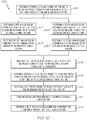
- the method 800 may further include, at block 802, positioning a first annular sealing component 600 between the first electrical isolator 300 and the flared end 108 of the first electrically conductive tube 100.
- the step, at block 802, of positioning the first annular sealing component 600 between the first electrical isolator 300 and the flared end 108 of the first electrically conductive tube 100 may further include, at block 803, positioning the first annular sealing component 600 in a first annular groove 314 disposed within the first electrical isolator 300.
- the method 800 may further include, at block 804, positioning a second annular sealing component 700 between the first electrical isolator 300 and the outer flange 208 of the second electrically conductive tube 200.
- the step, at block 804, of positioning the second annular sealing component 700 between the first electrical isolator 300 and the outer flange 208 of the second electrically conductive tube 200 may further include, at block 805, positioning the second annular sealing component 700 in a second annular groove 316 disposed within the first electrical isolator 300.
- the method 800 may further include, at block 801, positioning the first electrically conductive tube 100 and the second electrically conductive tube 200 within one of an aerial platform, a space platform, and an aerospace platform.
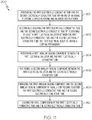
- Fig. 11 is a flow diagram of a method 900 for connecting the first electrically conductive tube 100 and the second electrically conductive tube 200.
- the method 900 includes, at block 902, electrically isolating the first electrically conductive tube 100 and the second electrically conductive tube 200 by positioning at least a first electrical isolator 300 between the first electrically conductive tube 100 and the second electrically conductive tube 200, the first electrical isolator 300 having a central passageway 304.
- the method 900 further includes, at block 904, positioning a first annular sealing component 600 between the first electrical isolator 300 and the first electrically conductive tube 100.
- the method 900 further includes, at block 906, positioning a second annular sealing component 700 between the first electrical isolator 300 and the second electrically conductive tube 200.
- the method 900 further includes, at block 908, energizing the first annular sealing component 600 and the second annular sealing component 700 by axially compressing together the first electrically conductive tube 100 and the second electrically conductive tube 200.
- the energizing of the first annular sealing component 600 and the second annular sealing component 700 by axially compressing together the first electrically conductive tube 100 and the second electrically conductive tube 200 may include but is not limited to use of nut 500 as previously described. However, other methods of axially compressing together the first electrically conductive tube 100 and the second electrically conductive tube 200 may be employed.
- the first annular sealing component 600 and the second annular sealing component 700 can be used to prevent fluid inside the first electrically conductive tube 100 and the second electrically conductive tube 200 from escaping under pressure.
- the method 900 may further include, at block 901, positioning the first electrically conductive tube 100 and the second electrically conductive tube 200 within one of an aerial platform, a space platform, and an aerospace platform.
- Examples of the present disclosure may be described in the context of an aircraft manufacturing and service method 1000, as shown in Fig. 12 and an aircraft 1002, as shown in Fig. 13 .
- the aircraft manufacturing and service method 1000 may include specification and design 1004 of the aircraft 1002 and material procurement 1006.
- component/subassembly manufacturing 1008 and system integration 1010 of the aircraft 1002 takes place.
- the aircraft 1002 may go through certification and delivery 1012 in order to be placed in service 1014.
- routine maintenance and service 1016 which may also include modification, reconfiguration, refurbishment and the like.
- a system integrator may include without limitation any number of aircraft manufacturers and major-system subcontractors; a third party may include without limitation any number of venders, subcontractors, and suppliers; and an operator may be an airline, leasing company, military entity, service organization, and so on.
- the apparatus and methods for connecting a first electrically conductive tube and a second electrically conductive tube of the present disclosure may be employed during any one or more of the stages of the aircraft manufacturing and service method 1000, including specification and design 1004 of the aircraft 1002, material procurement 1006, component/subassembly manufacturing 1008, system integration 1010, certification and delivery 1012, placing the aircraft in service 1014, and routine maintenance and service 1016.
- the aircraft 1002 produced by example method 1000 may include an airframe 1018 with a plurality of systems 1020 and an interior 1022.
- the plurality of systems 1020 may include one or more of a propulsion system 1024, an electrical system 1026, a hydraulic system 1028, and an environmental system 1030. Any number of other systems may be included.
- the apparatus and methods for connecting a first electrically conductive tube and a second electrically conductive tube of the present disclosure may be employed for any of the systems of the aircraft 1002.
Landscapes
- Engineering & Computer Science (AREA)
- General Engineering & Computer Science (AREA)
- Mechanical Engineering (AREA)
- Gasket Seals (AREA)
- Joints With Pressure Members (AREA)
- Flanged Joints, Insulating Joints, And Other Joints (AREA)
- Joints That Cut Off Fluids, And Hose Joints (AREA)
- Rigid Pipes And Flexible Pipes (AREA)
- Insulators (AREA)
Applications Claiming Priority (1)
| Application Number | Priority Date | Filing Date | Title |
|---|---|---|---|
| US16/212,926 US11098828B2 (en) | 2018-12-07 | 2018-12-07 | Apparatus and methods for connecting a first electrically conductive tube and a second electrically conductive tube |
Publications (2)
| Publication Number | Publication Date |
|---|---|
| EP3663625A1 true EP3663625A1 (de) | 2020-06-10 |
| EP3663625B1 EP3663625B1 (de) | 2022-08-24 |
Family
ID=68653368
Family Applications (1)
| Application Number | Title | Priority Date | Filing Date |
|---|---|---|---|
| EP19210686.2A Active EP3663625B1 (de) | 2018-12-07 | 2019-11-21 | Vorrichtung und verfahren zum verbinden eines ersten elektrisch leitenden rohrs und eines zweiten elektrisch leitenden rohrs |
Country Status (6)
| Country | Link |
|---|---|
| US (1) | US11098828B2 (de) |
| EP (1) | EP3663625B1 (de) |
| JP (1) | JP7449686B2 (de) |
| CN (1) | CN111288235B (de) |
| AU (1) | AU2019268047B2 (de) |
| CA (1) | CA3061728C (de) |
Citations (1)
| Publication number | Priority date | Publication date | Assignee | Title |
|---|---|---|---|---|
| EP0285387A2 (de) * | 1987-04-03 | 1988-10-05 | Cajon Company | Rohrverbindung |
Family Cites Families (49)
| Publication number | Priority date | Publication date | Assignee | Title |
|---|---|---|---|---|
| US1795570A (en) * | 1927-09-23 | 1931-03-10 | Patentaktiebolaget Velock | Locking device for nuts and screws |
| US2257385A (en) * | 1939-09-11 | 1941-09-30 | John G Keegan | Storage water heater |
| US2278479A (en) * | 1939-12-09 | 1942-04-07 | Arthur L Parker | Tube coupling |
| GB538497A (en) * | 1940-04-24 | 1941-08-06 | Oliver Edwin Simmonds | Improvements relating to self-locking nuts |
| US2578933A (en) * | 1947-12-02 | 1951-12-18 | Hunter | Coupling |
| GB687910A (en) * | 1950-08-03 | 1953-02-25 | Roy Wesley Ecoff | Improvements in electrically insulating pipe unions |
| US2794658A (en) * | 1951-05-19 | 1957-06-04 | Roy C Purkhiser | Insulated pipe union with dip tube hanger |
| US2757943A (en) * | 1952-05-14 | 1956-08-07 | Mueller Co | Pipe coupling with rubber gasket having an imbedded metallic split ring |
| US2752579A (en) * | 1953-03-30 | 1956-06-26 | Exxon Research Engineering Co | Pipe union with insulated contact plate |
| US2850299A (en) * | 1953-09-22 | 1958-09-02 | Dresser Ind | Flexible insulating coupling for threaded pipe |
| US2837351A (en) * | 1954-02-01 | 1958-06-03 | Cardox Corp | Electrically insulated pipe coupling with confined pressure-sealing means |
| US2867463A (en) * | 1955-03-21 | 1959-01-06 | American Coupler Company | Packing members for pipe joints and the like |
| US2950928A (en) * | 1957-12-17 | 1960-08-30 | Mueller Co | Insulated pipe joint |
| US3018119A (en) * | 1961-01-16 | 1962-01-23 | Eclipse Fuel Eng Co | Tamper-proof insulated pipe coupling |
| US3185501A (en) * | 1961-04-12 | 1965-05-25 | Mueller Co | Electrical insulating pipe coupling |
| JPS4419730Y1 (de) * | 1965-08-18 | 1969-08-23 | ||
| US3517950A (en) * | 1968-04-26 | 1970-06-30 | Dresser Ind | Insulating pipe union |
| GB1325476A (en) * | 1970-11-07 | 1973-08-01 | Hanson T A | Pipe union member |
| IT1088009B (it) * | 1976-10-18 | 1985-06-04 | Ziefle Kg Eisenbau Albert | Pezzo isolante di condotte tubolari |
| US4168731A (en) * | 1977-10-06 | 1979-09-25 | Taber Benjamin C | Locking nut and bolt assembly |
| FR2464424A1 (fr) * | 1979-09-03 | 1981-03-06 | Aerospatiale | Procede pour munir une canalisation d'un embout de raccord et canalisation ainsi obtenue |
| US4422674A (en) * | 1980-11-03 | 1983-12-27 | Rockwell International Corporation | Tamper proof gas meter |
| JPS5910587U (ja) * | 1982-07-13 | 1984-01-23 | 株式会社近江屋 | ユニオン |
| JPS59112087U (ja) * | 1983-01-19 | 1984-07-28 | 日立金属株式会社 | 絶縁ユニオン |
| US4595218A (en) * | 1983-08-04 | 1986-06-17 | Imperial Clevite Inc. | Insulative coupling |
| US4654747A (en) * | 1985-09-30 | 1987-03-31 | The Boeing Company | Dielectric isolation of metallic conduits |
| US4691944A (en) * | 1986-05-22 | 1987-09-08 | The Boeing Company | Tubing connector |
| JPH0474790U (de) * | 1990-10-31 | 1992-06-30 | ||
| US5131690A (en) * | 1991-07-29 | 1992-07-21 | Mano Michael E | Self-locking connector |
| DE4307092B4 (de) * | 1992-04-18 | 2008-08-21 | Neumayer Tekfor Holding Gmbh | Mutter, insbesondere Radmutter |
| JPH0840091A (ja) * | 1994-07-29 | 1996-02-13 | Toyoda Gosei Co Ltd | リテーナを持つ樹脂パイプ |
| US5447340A (en) * | 1994-09-21 | 1995-09-05 | Mueller Co. | Electrically insulated piped coupling employing a radial insulating barrier |
| US5735553A (en) * | 1996-03-08 | 1998-04-07 | Niemiec; Albin J. | Flared tube fitting for connecting flow conductors |
| JPH10169628A (ja) * | 1996-12-03 | 1998-06-23 | Mitsubishi Motors Corp | ナットの回り止め装置 |
| US6039524A (en) * | 1998-09-14 | 2000-03-21 | Hong Kong Disc-Lock Company Limited | Self-locking safety wheel nut with locking wrench |
| US6899358B2 (en) * | 2002-11-13 | 2005-05-31 | H. Gary Richardson | Hammer union and seal therefor |
| US20060099843A1 (en) * | 2004-11-01 | 2006-05-11 | Fullner Todd C | Dielectric fittings |
| US8956556B2 (en) * | 2008-07-02 | 2015-02-17 | Eaton Corporation | Dielectric isolators |
| BR122019021785B1 (pt) * | 2010-05-17 | 2020-12-01 | Parker Hannifin Gmbh | conjunto de encaixe dielétrico |
| US8434964B2 (en) | 2010-06-18 | 2013-05-07 | General Electric Company | Electrical isolator for couplings |
| US8939469B2 (en) | 2011-06-22 | 2015-01-27 | The Boeing Company | Static dissipative fluid conveying coupler |
| US8840740B2 (en) | 2011-06-24 | 2014-09-23 | The Boeing Company | Apparatus for preventing spark propagation |
| US9233758B2 (en) | 2011-12-16 | 2016-01-12 | The Boeing Corporation | Electrostatic discharge protected ferrule |
| US9688419B2 (en) | 2012-06-08 | 2017-06-27 | The Boeing Company | Composite tubes for a fluid transport system |
| US9255656B2 (en) * | 2012-08-07 | 2016-02-09 | United States Thermoamp Inc. | Fitting for a heat pump and method of installation |
| US8987612B2 (en) | 2012-11-26 | 2015-03-24 | The Boeing Company | Bushings, apparatuses including bushings, and associated methods |
| US10030798B2 (en) | 2013-02-18 | 2018-07-24 | The Boeing Company | Bulkhead fitting |
| JP6439677B2 (ja) * | 2013-03-11 | 2018-12-19 | 横浜ゴム株式会社 | 航空機用化粧室ユニットの水栓装置 |
| DE102013218479A1 (de) * | 2013-09-16 | 2015-03-19 | Robert Bosch Gmbh | Vorrichtung zur Erfassung mindestens einer Eigenschaft eines fluiden Mediums |
-
2018
- 2018-12-07 US US16/212,926 patent/US11098828B2/en active Active
-
2019
- 2019-11-14 CA CA3061728A patent/CA3061728C/en active Active
- 2019-11-18 AU AU2019268047A patent/AU2019268047B2/en active Active
- 2019-11-21 EP EP19210686.2A patent/EP3663625B1/de active Active
- 2019-12-05 CN CN201911235576.5A patent/CN111288235B/zh active Active
- 2019-12-06 JP JP2019220813A patent/JP7449686B2/ja active Active
Patent Citations (1)
| Publication number | Priority date | Publication date | Assignee | Title |
|---|---|---|---|---|
| EP0285387A2 (de) * | 1987-04-03 | 1988-10-05 | Cajon Company | Rohrverbindung |
Also Published As
| Publication number | Publication date |
|---|---|
| CN111288235A (zh) | 2020-06-16 |
| JP7449686B2 (ja) | 2024-03-14 |
| CA3061728C (en) | 2024-01-09 |
| AU2019268047A1 (en) | 2020-06-25 |
| US20200182384A1 (en) | 2020-06-11 |
| JP2020115035A (ja) | 2020-07-30 |
| AU2019268047B2 (en) | 2024-07-04 |
| CA3061728A1 (en) | 2020-06-07 |
| EP3663625B1 (de) | 2022-08-24 |
| CN111288235B (zh) | 2023-07-07 |
| US11098828B2 (en) | 2021-08-24 |
Similar Documents
| Publication | Publication Date | Title |
|---|---|---|
| JP6281960B2 (ja) | 電磁効果防御特性を有する自己整列型スリーブ付き突出ヘッド締め具 | |
| JP6399802B2 (ja) | 締め具システム及び締め具システムの製造方法 | |
| US11162616B2 (en) | Pass-through bulkhead seal fitting | |
| US10720728B2 (en) | Electrical connector sealing system | |
| US3139294A (en) | Flared tube fitting | |
| AU2014204509B2 (en) | Conductor connectors for power cables | |
| JP6703401B2 (ja) | 隔壁固定具 | |
| US10683954B2 (en) | Bulkhead connector assembly | |
| EP1627175B1 (de) | Verstellbares anschlussende mit geradem gewinde | |
| EP3663625A1 (de) | Vorrichtung und verfahren zum verbinden eines ersten elektrisch leitenden rohrs und eines zweiten elektrisch leitenden rohrs | |
| EP4227544A1 (de) | Strukturelle blindhülsen und zugehörige systeme und verfahren zum klemmen einer ersten struktur in bezug auf eine zweite struktur zur herstellung einer klemmstruktur | |
| US10141152B2 (en) | Drift chamber connection methods and apparatus | |
| EP3652070B1 (de) | Kraftstofftankkommunikationssysteme | |
| EP3002843A1 (de) | Hochspannungsverbindung | |
| US20260002561A1 (en) | Floating Seal Washers, Fastener Assemblies and Methods for Protection from Electromagnetic Effects | |
| US20190264837A1 (en) | Junction body, fittings, hydraulic system for the passage of a fluid between two hydraulic circuits, associated mounting process | |
| CN215862309U (zh) | 管路组件多级堵头及管路组件压力测试装置 | |
| CN119141266A (zh) | 一种可端面出水的刀具安装装置 |
Legal Events
| Date | Code | Title | Description |
|---|---|---|---|
| PUAI | Public reference made under article 153(3) epc to a published international application that has entered the european phase |
Free format text: ORIGINAL CODE: 0009012 |
|
| STAA | Information on the status of an ep patent application or granted ep patent |
Free format text: STATUS: THE APPLICATION HAS BEEN PUBLISHED |
|
| AK | Designated contracting states |
Kind code of ref document: A1 Designated state(s): AL AT BE BG CH CY CZ DE DK EE ES FI FR GB GR HR HU IE IS IT LI LT LU LV MC MK MT NL NO PL PT RO RS SE SI SK SM TR |
|
| AX | Request for extension of the european patent |
Extension state: BA ME |
|
| STAA | Information on the status of an ep patent application or granted ep patent |
Free format text: STATUS: REQUEST FOR EXAMINATION WAS MADE |
|
| 17P | Request for examination filed |
Effective date: 20201123 |
|
| RBV | Designated contracting states (corrected) |
Designated state(s): AL AT BE BG CH CY CZ DE DK EE ES FI FR GB GR HR HU IE IS IT LI LT LU LV MC MK MT NL NO PL PT RO RS SE SI SK SM TR |
|
| GRAP | Despatch of communication of intention to grant a patent |
Free format text: ORIGINAL CODE: EPIDOSNIGR1 |
|
| STAA | Information on the status of an ep patent application or granted ep patent |
Free format text: STATUS: GRANT OF PATENT IS INTENDED |
|
| INTG | Intention to grant announced |
Effective date: 20211013 |
|
| GRAJ | Information related to disapproval of communication of intention to grant by the applicant or resumption of examination proceedings by the epo deleted |
Free format text: ORIGINAL CODE: EPIDOSDIGR1 |
|
| STAA | Information on the status of an ep patent application or granted ep patent |
Free format text: STATUS: REQUEST FOR EXAMINATION WAS MADE |
|
| INTC | Intention to grant announced (deleted) | ||
| GRAP | Despatch of communication of intention to grant a patent |
Free format text: ORIGINAL CODE: EPIDOSNIGR1 |
|
| STAA | Information on the status of an ep patent application or granted ep patent |
Free format text: STATUS: GRANT OF PATENT IS INTENDED |
|
| INTG | Intention to grant announced |
Effective date: 20220401 |
|
| GRAS | Grant fee paid |
Free format text: ORIGINAL CODE: EPIDOSNIGR3 |
|
| GRAA | (expected) grant |
Free format text: ORIGINAL CODE: 0009210 |
|
| STAA | Information on the status of an ep patent application or granted ep patent |
Free format text: STATUS: THE PATENT HAS BEEN GRANTED |
|
| AK | Designated contracting states |
Kind code of ref document: B1 Designated state(s): AL AT BE BG CH CY CZ DE DK EE ES FI FR GB GR HR HU IE IS IT LI LT LU LV MC MK MT NL NO PL PT RO RS SE SI SK SM TR |
|
| REG | Reference to a national code |
Ref country code: CH Ref legal event code: EP |
|
| REG | Reference to a national code |
Ref country code: IE Ref legal event code: FG4D |
|
| REG | Reference to a national code |
Ref country code: AT Ref legal event code: REF Ref document number: 1513878 Country of ref document: AT Kind code of ref document: T Effective date: 20220915 Ref country code: DE Ref legal event code: R096 Ref document number: 602019018611 Country of ref document: DE |
|
| REG | Reference to a national code |
Ref country code: LT Ref legal event code: MG9D |
|
| REG | Reference to a national code |
Ref country code: NL Ref legal event code: MP Effective date: 20220824 |
|
| PG25 | Lapsed in a contracting state [announced via postgrant information from national office to epo] |
Ref country code: SE Free format text: LAPSE BECAUSE OF FAILURE TO SUBMIT A TRANSLATION OF THE DESCRIPTION OR TO PAY THE FEE WITHIN THE PRESCRIBED TIME-LIMIT Effective date: 20220824 Ref country code: RS Free format text: LAPSE BECAUSE OF FAILURE TO SUBMIT A TRANSLATION OF THE DESCRIPTION OR TO PAY THE FEE WITHIN THE PRESCRIBED TIME-LIMIT Effective date: 20220824 Ref country code: PT Free format text: LAPSE BECAUSE OF FAILURE TO SUBMIT A TRANSLATION OF THE DESCRIPTION OR TO PAY THE FEE WITHIN THE PRESCRIBED TIME-LIMIT Effective date: 20221226 Ref country code: NO Free format text: LAPSE BECAUSE OF FAILURE TO SUBMIT A TRANSLATION OF THE DESCRIPTION OR TO PAY THE FEE WITHIN THE PRESCRIBED TIME-LIMIT Effective date: 20221124 Ref country code: NL Free format text: LAPSE BECAUSE OF FAILURE TO SUBMIT A TRANSLATION OF THE DESCRIPTION OR TO PAY THE FEE WITHIN THE PRESCRIBED TIME-LIMIT Effective date: 20220824 Ref country code: LV Free format text: LAPSE BECAUSE OF FAILURE TO SUBMIT A TRANSLATION OF THE DESCRIPTION OR TO PAY THE FEE WITHIN THE PRESCRIBED TIME-LIMIT Effective date: 20220824 Ref country code: LT Free format text: LAPSE BECAUSE OF FAILURE TO SUBMIT A TRANSLATION OF THE DESCRIPTION OR TO PAY THE FEE WITHIN THE PRESCRIBED TIME-LIMIT Effective date: 20220824 Ref country code: FI Free format text: LAPSE BECAUSE OF FAILURE TO SUBMIT A TRANSLATION OF THE DESCRIPTION OR TO PAY THE FEE WITHIN THE PRESCRIBED TIME-LIMIT Effective date: 20220824 |
|
| REG | Reference to a national code |
Ref country code: AT Ref legal event code: MK05 Ref document number: 1513878 Country of ref document: AT Kind code of ref document: T Effective date: 20220824 |
|
| PG25 | Lapsed in a contracting state [announced via postgrant information from national office to epo] |
Ref country code: PL Free format text: LAPSE BECAUSE OF FAILURE TO SUBMIT A TRANSLATION OF THE DESCRIPTION OR TO PAY THE FEE WITHIN THE PRESCRIBED TIME-LIMIT Effective date: 20220824 Ref country code: IS Free format text: LAPSE BECAUSE OF FAILURE TO SUBMIT A TRANSLATION OF THE DESCRIPTION OR TO PAY THE FEE WITHIN THE PRESCRIBED TIME-LIMIT Effective date: 20221224 Ref country code: HR Free format text: LAPSE BECAUSE OF FAILURE TO SUBMIT A TRANSLATION OF THE DESCRIPTION OR TO PAY THE FEE WITHIN THE PRESCRIBED TIME-LIMIT Effective date: 20220824 Ref country code: GR Free format text: LAPSE BECAUSE OF FAILURE TO SUBMIT A TRANSLATION OF THE DESCRIPTION OR TO PAY THE FEE WITHIN THE PRESCRIBED TIME-LIMIT Effective date: 20221125 |
|
| RAP4 | Party data changed (patent owner data changed or rights of a patent transferred) |
Owner name: THE BOEING COMPANY |
|
| PG25 | Lapsed in a contracting state [announced via postgrant information from national office to epo] |
Ref country code: SM Free format text: LAPSE BECAUSE OF FAILURE TO SUBMIT A TRANSLATION OF THE DESCRIPTION OR TO PAY THE FEE WITHIN THE PRESCRIBED TIME-LIMIT Effective date: 20220824 Ref country code: RO Free format text: LAPSE BECAUSE OF FAILURE TO SUBMIT A TRANSLATION OF THE DESCRIPTION OR TO PAY THE FEE WITHIN THE PRESCRIBED TIME-LIMIT Effective date: 20220824 Ref country code: ES Free format text: LAPSE BECAUSE OF FAILURE TO SUBMIT A TRANSLATION OF THE DESCRIPTION OR TO PAY THE FEE WITHIN THE PRESCRIBED TIME-LIMIT Effective date: 20220824 Ref country code: DK Free format text: LAPSE BECAUSE OF FAILURE TO SUBMIT A TRANSLATION OF THE DESCRIPTION OR TO PAY THE FEE WITHIN THE PRESCRIBED TIME-LIMIT Effective date: 20220824 Ref country code: CZ Free format text: LAPSE BECAUSE OF FAILURE TO SUBMIT A TRANSLATION OF THE DESCRIPTION OR TO PAY THE FEE WITHIN THE PRESCRIBED TIME-LIMIT Effective date: 20220824 Ref country code: AT Free format text: LAPSE BECAUSE OF FAILURE TO SUBMIT A TRANSLATION OF THE DESCRIPTION OR TO PAY THE FEE WITHIN THE PRESCRIBED TIME-LIMIT Effective date: 20220824 |
|
| REG | Reference to a national code |
Ref country code: DE Ref legal event code: R097 Ref document number: 602019018611 Country of ref document: DE |
|
| PG25 | Lapsed in a contracting state [announced via postgrant information from national office to epo] |
Ref country code: SK Free format text: LAPSE BECAUSE OF FAILURE TO SUBMIT A TRANSLATION OF THE DESCRIPTION OR TO PAY THE FEE WITHIN THE PRESCRIBED TIME-LIMIT Effective date: 20220824 Ref country code: EE Free format text: LAPSE BECAUSE OF FAILURE TO SUBMIT A TRANSLATION OF THE DESCRIPTION OR TO PAY THE FEE WITHIN THE PRESCRIBED TIME-LIMIT Effective date: 20220824 |
|
| P01 | Opt-out of the competence of the unified patent court (upc) registered |
Effective date: 20230516 |
|
| PG25 | Lapsed in a contracting state [announced via postgrant information from national office to epo] |
Ref country code: MC Free format text: LAPSE BECAUSE OF FAILURE TO SUBMIT A TRANSLATION OF THE DESCRIPTION OR TO PAY THE FEE WITHIN THE PRESCRIBED TIME-LIMIT Effective date: 20220824 Ref country code: AL Free format text: LAPSE BECAUSE OF FAILURE TO SUBMIT A TRANSLATION OF THE DESCRIPTION OR TO PAY THE FEE WITHIN THE PRESCRIBED TIME-LIMIT Effective date: 20220824 |
|
| PLBE | No opposition filed within time limit |
Free format text: ORIGINAL CODE: 0009261 |
|
| REG | Reference to a national code |
Ref country code: CH Ref legal event code: PL |
|
| STAA | Information on the status of an ep patent application or granted ep patent |
Free format text: STATUS: NO OPPOSITION FILED WITHIN TIME LIMIT |
|
| REG | Reference to a national code |
Ref country code: BE Ref legal event code: MM Effective date: 20221130 |
|
| PG25 | Lapsed in a contracting state [announced via postgrant information from national office to epo] |
Ref country code: LI Free format text: LAPSE BECAUSE OF NON-PAYMENT OF DUE FEES Effective date: 20221130 Ref country code: CH Free format text: LAPSE BECAUSE OF NON-PAYMENT OF DUE FEES Effective date: 20221130 |
|
| 26N | No opposition filed |
Effective date: 20230525 |
|
| PG25 | Lapsed in a contracting state [announced via postgrant information from national office to epo] |
Ref country code: SI Free format text: LAPSE BECAUSE OF FAILURE TO SUBMIT A TRANSLATION OF THE DESCRIPTION OR TO PAY THE FEE WITHIN THE PRESCRIBED TIME-LIMIT Effective date: 20220824 Ref country code: LU Free format text: LAPSE BECAUSE OF NON-PAYMENT OF DUE FEES Effective date: 20221121 |
|
| PG25 | Lapsed in a contracting state [announced via postgrant information from national office to epo] |
Ref country code: IE Free format text: LAPSE BECAUSE OF NON-PAYMENT OF DUE FEES Effective date: 20221121 |
|
| PG25 | Lapsed in a contracting state [announced via postgrant information from national office to epo] |
Ref country code: BE Free format text: LAPSE BECAUSE OF NON-PAYMENT OF DUE FEES Effective date: 20221130 |
|
| PG25 | Lapsed in a contracting state [announced via postgrant information from national office to epo] |
Ref country code: HU Free format text: LAPSE BECAUSE OF FAILURE TO SUBMIT A TRANSLATION OF THE DESCRIPTION OR TO PAY THE FEE WITHIN THE PRESCRIBED TIME-LIMIT; INVALID AB INITIO Effective date: 20191121 |
|
| PG25 | Lapsed in a contracting state [announced via postgrant information from national office to epo] |
Ref country code: CY Free format text: LAPSE BECAUSE OF FAILURE TO SUBMIT A TRANSLATION OF THE DESCRIPTION OR TO PAY THE FEE WITHIN THE PRESCRIBED TIME-LIMIT Effective date: 20220824 |
|
| PG25 | Lapsed in a contracting state [announced via postgrant information from national office to epo] |
Ref country code: MK Free format text: LAPSE BECAUSE OF FAILURE TO SUBMIT A TRANSLATION OF THE DESCRIPTION OR TO PAY THE FEE WITHIN THE PRESCRIBED TIME-LIMIT Effective date: 20220824 Ref country code: IT Free format text: LAPSE BECAUSE OF FAILURE TO SUBMIT A TRANSLATION OF THE DESCRIPTION OR TO PAY THE FEE WITHIN THE PRESCRIBED TIME-LIMIT Effective date: 20220824 |
|
| PG25 | Lapsed in a contracting state [announced via postgrant information from national office to epo] |
Ref country code: BG Free format text: LAPSE BECAUSE OF FAILURE TO SUBMIT A TRANSLATION OF THE DESCRIPTION OR TO PAY THE FEE WITHIN THE PRESCRIBED TIME-LIMIT Effective date: 20220824 |
|
| PG25 | Lapsed in a contracting state [announced via postgrant information from national office to epo] |
Ref country code: MT Free format text: LAPSE BECAUSE OF FAILURE TO SUBMIT A TRANSLATION OF THE DESCRIPTION OR TO PAY THE FEE WITHIN THE PRESCRIBED TIME-LIMIT Effective date: 20220824 |
|
| PG25 | Lapsed in a contracting state [announced via postgrant information from national office to epo] |
Ref country code: TR Free format text: LAPSE BECAUSE OF FAILURE TO SUBMIT A TRANSLATION OF THE DESCRIPTION OR TO PAY THE FEE WITHIN THE PRESCRIBED TIME-LIMIT Effective date: 20220824 |
|
| PGFP | Annual fee paid to national office [announced via postgrant information from national office to epo] |
Ref country code: DE Payment date: 20251128 Year of fee payment: 7 |
|
| PGFP | Annual fee paid to national office [announced via postgrant information from national office to epo] |
Ref country code: GB Payment date: 20251127 Year of fee payment: 7 |
|
| PGFP | Annual fee paid to national office [announced via postgrant information from national office to epo] |
Ref country code: FR Payment date: 20251125 Year of fee payment: 7 |