EP3663524B1 - Schéma de refroidissement à flux axial avec nervure structurale pour un moteur à turbine à gaz - Google Patents
Schéma de refroidissement à flux axial avec nervure structurale pour un moteur à turbine à gaz Download PDFInfo
- Publication number
- EP3663524B1 EP3663524B1 EP19213966.5A EP19213966A EP3663524B1 EP 3663524 B1 EP3663524 B1 EP 3663524B1 EP 19213966 A EP19213966 A EP 19213966A EP 3663524 B1 EP3663524 B1 EP 3663524B1
- Authority
- EP
- European Patent Office
- Prior art keywords
- sidewall
- axial
- structural rib
- standoff ribs
- vane
- Prior art date
- Legal status (The legal status is an assumption and is not a legal conclusion. Google has not performed a legal analysis and makes no representation as to the accuracy of the status listed.)
- Active
Links
- 238000001816 cooling Methods 0.000 title claims description 18
- 239000011162 core material Substances 0.000 description 13
- 238000004519 manufacturing process Methods 0.000 description 12
- 239000007789 gas Substances 0.000 description 9
- 238000005266 casting Methods 0.000 description 6
- 239000000654 additive Substances 0.000 description 5
- 230000000996 additive effect Effects 0.000 description 5
- 239000000463 material Substances 0.000 description 5
- 238000000034 method Methods 0.000 description 5
- 229910000601 superalloy Inorganic materials 0.000 description 5
- PXHVJJICTQNCMI-UHFFFAOYSA-N Nickel Chemical compound [Ni] PXHVJJICTQNCMI-UHFFFAOYSA-N 0.000 description 4
- 229910045601 alloy Inorganic materials 0.000 description 4
- 239000000956 alloy Substances 0.000 description 4
- 239000000919 ceramic Substances 0.000 description 4
- 239000000567 combustion gas Substances 0.000 description 4
- 238000010894 electron beam technology Methods 0.000 description 4
- 238000013459 approach Methods 0.000 description 3
- 230000008901 benefit Effects 0.000 description 3
- 239000000843 powder Substances 0.000 description 3
- 238000007711 solidification Methods 0.000 description 3
- 230000008023 solidification Effects 0.000 description 3
- 238000010146 3D printing Methods 0.000 description 2
- XEEYBQQBJWHFJM-UHFFFAOYSA-N Iron Chemical compound [Fe] XEEYBQQBJWHFJM-UHFFFAOYSA-N 0.000 description 2
- 230000005540 biological transmission Effects 0.000 description 2
- 238000004891 communication Methods 0.000 description 2
- 239000013078 crystal Substances 0.000 description 2
- 238000000151 deposition Methods 0.000 description 2
- 230000008021 deposition Effects 0.000 description 2
- 239000000446 fuel Substances 0.000 description 2
- 230000004927 fusion Effects 0.000 description 2
- 229910001119 inconels 625 Inorganic materials 0.000 description 2
- 229910000816 inconels 718 Inorganic materials 0.000 description 2
- 239000007788 liquid Substances 0.000 description 2
- 230000008018 melting Effects 0.000 description 2
- 238000002844 melting Methods 0.000 description 2
- 229910052759 nickel Inorganic materials 0.000 description 2
- 239000003870 refractory metal Substances 0.000 description 2
- 238000000110 selective laser sintering Methods 0.000 description 2
- 239000007787 solid Substances 0.000 description 2
- 239000007858 starting material Substances 0.000 description 2
- 238000012546 transfer Methods 0.000 description 2
- 239000004215 Carbon black (E152) Substances 0.000 description 1
- 229910000684 Cobalt-chrome Inorganic materials 0.000 description 1
- 229910001069 Ti alloy Inorganic materials 0.000 description 1
- RTAQQCXQSZGOHL-UHFFFAOYSA-N Titanium Chemical compound [Ti] RTAQQCXQSZGOHL-UHFFFAOYSA-N 0.000 description 1
- 229910001315 Tool steel Inorganic materials 0.000 description 1
- 229910052782 aluminium Inorganic materials 0.000 description 1
- XAGFODPZIPBFFR-UHFFFAOYSA-N aluminium Chemical compound [Al] XAGFODPZIPBFFR-UHFFFAOYSA-N 0.000 description 1
- 238000000149 argon plasma sintering Methods 0.000 description 1
- 238000000429 assembly Methods 0.000 description 1
- 230000000712 assembly Effects 0.000 description 1
- 239000011230 binding agent Substances 0.000 description 1
- 229910017052 cobalt Inorganic materials 0.000 description 1
- 239000010941 cobalt Substances 0.000 description 1
- GUTLYIVDDKVIGB-UHFFFAOYSA-N cobalt atom Chemical compound [Co] GUTLYIVDDKVIGB-UHFFFAOYSA-N 0.000 description 1
- 239000010952 cobalt-chrome Substances 0.000 description 1
- 238000002485 combustion reaction Methods 0.000 description 1
- 230000006835 compression Effects 0.000 description 1
- 238000007906 compression Methods 0.000 description 1
- 238000010586 diagram Methods 0.000 description 1
- 238000009792 diffusion process Methods 0.000 description 1
- 229930195733 hydrocarbon Natural products 0.000 description 1
- 150000002430 hydrocarbons Chemical class 0.000 description 1
- 230000006698 induction Effects 0.000 description 1
- 229910052742 iron Inorganic materials 0.000 description 1
- 238000002955 isolation Methods 0.000 description 1
- 229910052751 metal Inorganic materials 0.000 description 1
- 239000002184 metal Substances 0.000 description 1
- 238000001465 metallisation Methods 0.000 description 1
- 150000002739 metals Chemical class 0.000 description 1
- 239000000203 mixture Substances 0.000 description 1
- 238000012986 modification Methods 0.000 description 1
- 230000004048 modification Effects 0.000 description 1
- 239000004033 plastic Substances 0.000 description 1
- 229920003023 plastic Polymers 0.000 description 1
- 229920000642 polymer Polymers 0.000 description 1
- 238000007639 printing Methods 0.000 description 1
- 230000008569 process Effects 0.000 description 1
- 230000009467 reduction Effects 0.000 description 1
- 239000011214 refractory ceramic Substances 0.000 description 1
- 229920005989 resin Polymers 0.000 description 1
- 239000011347 resin Substances 0.000 description 1
- 230000004044 response Effects 0.000 description 1
- 238000007493 shaping process Methods 0.000 description 1
- 238000005245 sintering Methods 0.000 description 1
- 229910001220 stainless steel Inorganic materials 0.000 description 1
- 239000010935 stainless steel Substances 0.000 description 1
- 239000010936 titanium Substances 0.000 description 1
- 229910052719 titanium Inorganic materials 0.000 description 1
Images


Classifications
-
- F—MECHANICAL ENGINEERING; LIGHTING; HEATING; WEAPONS; BLASTING
- F01—MACHINES OR ENGINES IN GENERAL; ENGINE PLANTS IN GENERAL; STEAM ENGINES
- F01D—NON-POSITIVE DISPLACEMENT MACHINES OR ENGINES, e.g. STEAM TURBINES
- F01D5/00—Blades; Blade-carrying members; Heating, heat-insulating, cooling or antivibration means on the blades or the members
- F01D5/12—Blades
- F01D5/14—Form or construction
- F01D5/18—Hollow blades, i.e. blades with cooling or heating channels or cavities; Heating, heat-insulating or cooling means on blades
- F01D5/187—Convection cooling
-
- F—MECHANICAL ENGINEERING; LIGHTING; HEATING; WEAPONS; BLASTING
- F01—MACHINES OR ENGINES IN GENERAL; ENGINE PLANTS IN GENERAL; STEAM ENGINES
- F01D—NON-POSITIVE DISPLACEMENT MACHINES OR ENGINES, e.g. STEAM TURBINES
- F01D5/00—Blades; Blade-carrying members; Heating, heat-insulating, cooling or antivibration means on the blades or the members
- F01D5/12—Blades
- F01D5/14—Form or construction
- F01D5/18—Hollow blades, i.e. blades with cooling or heating channels or cavities; Heating, heat-insulating or cooling means on blades
- F01D5/186—Film cooling
-
- F—MECHANICAL ENGINEERING; LIGHTING; HEATING; WEAPONS; BLASTING
- F01—MACHINES OR ENGINES IN GENERAL; ENGINE PLANTS IN GENERAL; STEAM ENGINES
- F01D—NON-POSITIVE DISPLACEMENT MACHINES OR ENGINES, e.g. STEAM TURBINES
- F01D5/00—Blades; Blade-carrying members; Heating, heat-insulating, cooling or antivibration means on the blades or the members
- F01D5/12—Blades
- F01D5/14—Form or construction
- F01D5/18—Hollow blades, i.e. blades with cooling or heating channels or cavities; Heating, heat-insulating or cooling means on blades
- F01D5/187—Convection cooling
- F01D5/188—Convection cooling with an insert in the blade cavity to guide the cooling fluid, e.g. forming a separation wall
- F01D5/189—Convection cooling with an insert in the blade cavity to guide the cooling fluid, e.g. forming a separation wall the insert having a tubular cross-section, e.g. airfoil shape
-
- F—MECHANICAL ENGINEERING; LIGHTING; HEATING; WEAPONS; BLASTING
- F01—MACHINES OR ENGINES IN GENERAL; ENGINE PLANTS IN GENERAL; STEAM ENGINES
- F01D—NON-POSITIVE DISPLACEMENT MACHINES OR ENGINES, e.g. STEAM TURBINES
- F01D9/00—Stators
- F01D9/02—Nozzles; Nozzle boxes; Stator blades; Guide conduits, e.g. individual nozzles
- F01D9/04—Nozzles; Nozzle boxes; Stator blades; Guide conduits, e.g. individual nozzles forming ring or sector
- F01D9/041—Nozzles; Nozzle boxes; Stator blades; Guide conduits, e.g. individual nozzles forming ring or sector using blades
-
- F—MECHANICAL ENGINEERING; LIGHTING; HEATING; WEAPONS; BLASTING
- F05—INDEXING SCHEMES RELATING TO ENGINES OR PUMPS IN VARIOUS SUBCLASSES OF CLASSES F01-F04
- F05D—INDEXING SCHEME FOR ASPECTS RELATING TO NON-POSITIVE-DISPLACEMENT MACHINES OR ENGINES, GAS-TURBINES OR JET-PROPULSION PLANTS
- F05D2230/00—Manufacture
- F05D2230/20—Manufacture essentially without removing material
- F05D2230/21—Manufacture essentially without removing material by casting
- F05D2230/211—Manufacture essentially without removing material by casting by precision casting, e.g. microfusing or investment casting
-
- F—MECHANICAL ENGINEERING; LIGHTING; HEATING; WEAPONS; BLASTING
- F05—INDEXING SCHEMES RELATING TO ENGINES OR PUMPS IN VARIOUS SUBCLASSES OF CLASSES F01-F04
- F05D—INDEXING SCHEME FOR ASPECTS RELATING TO NON-POSITIVE-DISPLACEMENT MACHINES OR ENGINES, GAS-TURBINES OR JET-PROPULSION PLANTS
- F05D2230/00—Manufacture
- F05D2230/30—Manufacture with deposition of material
- F05D2230/31—Layer deposition
-
- F—MECHANICAL ENGINEERING; LIGHTING; HEATING; WEAPONS; BLASTING
- F05—INDEXING SCHEMES RELATING TO ENGINES OR PUMPS IN VARIOUS SUBCLASSES OF CLASSES F01-F04
- F05D—INDEXING SCHEME FOR ASPECTS RELATING TO NON-POSITIVE-DISPLACEMENT MACHINES OR ENGINES, GAS-TURBINES OR JET-PROPULSION PLANTS
- F05D2240/00—Components
- F05D2240/10—Stators
- F05D2240/12—Fluid guiding means, e.g. vanes
- F05D2240/126—Baffles or ribs
-
- F—MECHANICAL ENGINEERING; LIGHTING; HEATING; WEAPONS; BLASTING
- F05—INDEXING SCHEMES RELATING TO ENGINES OR PUMPS IN VARIOUS SUBCLASSES OF CLASSES F01-F04
- F05D—INDEXING SCHEME FOR ASPECTS RELATING TO NON-POSITIVE-DISPLACEMENT MACHINES OR ENGINES, GAS-TURBINES OR JET-PROPULSION PLANTS
- F05D2260/00—Function
- F05D2260/20—Heat transfer, e.g. cooling
- F05D2260/221—Improvement of heat transfer
- F05D2260/2214—Improvement of heat transfer by increasing the heat transfer surface
- F05D2260/22141—Improvement of heat transfer by increasing the heat transfer surface using fins or ribs
-
- F—MECHANICAL ENGINEERING; LIGHTING; HEATING; WEAPONS; BLASTING
- F05—INDEXING SCHEMES RELATING TO ENGINES OR PUMPS IN VARIOUS SUBCLASSES OF CLASSES F01-F04
- F05D—INDEXING SCHEME FOR ASPECTS RELATING TO NON-POSITIVE-DISPLACEMENT MACHINES OR ENGINES, GAS-TURBINES OR JET-PROPULSION PLANTS
- F05D2300/00—Materials; Properties thereof
- F05D2300/10—Metals, alloys or intermetallic compounds
- F05D2300/17—Alloys
- F05D2300/171—Steel alloys
-
- F—MECHANICAL ENGINEERING; LIGHTING; HEATING; WEAPONS; BLASTING
- F05—INDEXING SCHEMES RELATING TO ENGINES OR PUMPS IN VARIOUS SUBCLASSES OF CLASSES F01-F04
- F05D—INDEXING SCHEME FOR ASPECTS RELATING TO NON-POSITIVE-DISPLACEMENT MACHINES OR ENGINES, GAS-TURBINES OR JET-PROPULSION PLANTS
- F05D2300/00—Materials; Properties thereof
- F05D2300/10—Metals, alloys or intermetallic compounds
- F05D2300/17—Alloys
- F05D2300/174—Titanium alloys, e.g. TiAl
-
- F—MECHANICAL ENGINEERING; LIGHTING; HEATING; WEAPONS; BLASTING
- F05—INDEXING SCHEMES RELATING TO ENGINES OR PUMPS IN VARIOUS SUBCLASSES OF CLASSES F01-F04
- F05D—INDEXING SCHEME FOR ASPECTS RELATING TO NON-POSITIVE-DISPLACEMENT MACHINES OR ENGINES, GAS-TURBINES OR JET-PROPULSION PLANTS
- F05D2300/00—Materials; Properties thereof
- F05D2300/10—Metals, alloys or intermetallic compounds
- F05D2300/17—Alloys
- F05D2300/175—Superalloys
-
- F—MECHANICAL ENGINEERING; LIGHTING; HEATING; WEAPONS; BLASTING
- F05—INDEXING SCHEMES RELATING TO ENGINES OR PUMPS IN VARIOUS SUBCLASSES OF CLASSES F01-F04
- F05D—INDEXING SCHEME FOR ASPECTS RELATING TO NON-POSITIVE-DISPLACEMENT MACHINES OR ENGINES, GAS-TURBINES OR JET-PROPULSION PLANTS
- F05D2300/00—Materials; Properties thereof
- F05D2300/20—Oxide or non-oxide ceramics
-
- F—MECHANICAL ENGINEERING; LIGHTING; HEATING; WEAPONS; BLASTING
- F05—INDEXING SCHEMES RELATING TO ENGINES OR PUMPS IN VARIOUS SUBCLASSES OF CLASSES F01-F04
- F05D—INDEXING SCHEME FOR ASPECTS RELATING TO NON-POSITIVE-DISPLACEMENT MACHINES OR ENGINES, GAS-TURBINES OR JET-PROPULSION PLANTS
- F05D2300/00—Materials; Properties thereof
- F05D2300/40—Organic materials
- F05D2300/43—Synthetic polymers, e.g. plastics; Rubber
-
- F—MECHANICAL ENGINEERING; LIGHTING; HEATING; WEAPONS; BLASTING
- F05—INDEXING SCHEMES RELATING TO ENGINES OR PUMPS IN VARIOUS SUBCLASSES OF CLASSES F01-F04
- F05D—INDEXING SCHEME FOR ASPECTS RELATING TO NON-POSITIVE-DISPLACEMENT MACHINES OR ENGINES, GAS-TURBINES OR JET-PROPULSION PLANTS
- F05D2300/00—Materials; Properties thereof
- F05D2300/60—Properties or characteristics given to material by treatment or manufacturing
- F05D2300/607—Monocrystallinity
Definitions
- the present disclosure relates to a gas turbine engine and, more particularly, to a cooling scheme for an airfoil.
- Gas turbine engines typically include a compressor section to pressurize flow, a combustor section to burn a hydrocarbon fuel in the presence of the pressurized air, and a turbine section to extract energy from the resultant combustion gases.
- the combustion gases commonly exceed 2000 degrees F (1093 degrees C).
- Cooling of engine components is performed via communication of cooling flow through airfoil cooling circuits. Due to casting size limitations of trailing edge slots from the airfoil cooling circuit, trailing edge flow provides a significant portion of the cooling flow in a component. Axial flow baffle designs can utilize this trailing edge flow efficiently to cool the balance of the component, eliminating the complexity of dedicated cooling flow in other regions of the component. However, in order to prevent the pressure and suction side walls from bulging with minimal weight impact, stiffening features are utilized to tie the pressure and suction side walls together which may further interfere with the flow.
- EP 1 221 538 A2 discloses a prior art turbine vane for a gas turbine engine as set forth in the preamble of claim 1.
- EP 3 321 474 A1 discloses another prior art turbine vane for a gas turbine engine.
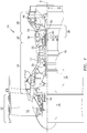
- FIG. 1 schematically illustrates a gas turbine engine 20.
- the gas turbine engine 20 is disclosed herein as a two-spool turbo fan that generally incorporates a fan section 22, a compressor section 24, a combustor section 26 and a turbine section 28.
- the fan section 22 drives air along a bypass flowpath while the compressor section 24 drives air along a core flowpath for compression and communication into the combustor section 26 then expansion through the turbine section 28.
- the concepts described herein may be applied to other turbine engine architectures such as turbojets, turboshafts, and three-spool (plus fan) turbofans.
- the engine 20 generally includes a low spool 30 and a high spool 32 mounted for rotation about an engine central longitudinal axis A relative to an engine case structure 36 via several bearing structures 38.
- the low spool 30 generally includes an inner shaft 40 that interconnects a fan 42, a low pressure compressor (“LPC”) 44 and a low pressure turbine (“LPT”) 46.
- the inner shaft 40 drives the fan 42 directly or through a geared architecture 48 to drive the fan 42 at a lower speed than the low spool 30.
- An exemplary reduction transmission is an epicyclic transmission, namely a planetary or star gear system.
- the high spool 32 includes an outer shaft 50 that interconnects a high pressure compressor (“HPC”) 52 and high pressure turbine (“HPT”) 54.
- a combustor 56 is arranged between the high pressure compressor 52 and the high pressure turbine 54.
- the inner shaft 40 and the outer shaft 50 are concentric and rotate about the engine central longitudinal axis A which is collinear with their longitudinal axes.
- Core flow is compressed by the LPC 44 then the HPC 52, mixed with the fuel and burned in the combustor 56, then the combustion gasses are expanded over the HPT 54 and the LPT 46.
- the turbines 46, 54 rotationally drive the respective low spool 30 and high spool 32 in response to the expansion.
- the main engine shafts 40, 50 are supported at a plurality of points by bearing assemblies 38 within the engine case structure 36.
- a full ring shroud assembly 60 within the engine case structure 36 supports a blade outer air seal (BOAS) assembly 62.
- the blade outer air seal (BOAS) assembly 62 contains a multiple of circumferentially distributed BOAS 64 proximate to a rotor assembly 66.
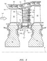
- the full ring shroud assembly 60 and the blade outer air seal (BOAS) assembly 62 are axially disposed adjacent to a first stationary vane ring 68 (also shown in FIG 3 ).
- the vane ring 68 includes an array of vanes 70 between a respective inner vane platform 72 and an outer vane platform 74.
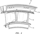
- the array of vanes 70 are formed as a multiple of vane doublets 75 (one shown in FIG. 4 ), however, other turbine component and vane arrangements will benefit herefrom.
- the outer vane platform 74 attach the vane ring 68 to the engine case structure 36.
- the single rotor assembly 66 and the single stationary vane ring 68 are described in detail as representative of any number of multiple engine stages.
- the first stationary vane ring 68 may be mounted to the engine case structure 36 by a multiple of segmented hooked rails 76 that extend from the outer vane platform 74.
- a full hoop inner air seal 78 that attaches to the inner vane platform 72 provides a seal surface for a full hoop cover plate 80 mounted to each rotor assembly 66.
- the full hoop inner air seal 78 includes a multiple of feed passages 82 that supply cooling air "C" to an airfoil cooling circuit 84 distributed within each respective vane 70.
- Each vane 70 receives the cooling air "C" from multiple of feed passages 82 that feeds a plenum 86 thence into each airfoil cooling circuit 84.
- one disclosed embodiment of the vane 70 includes an airfoil 100 that defines a blade chord between a leading edge 102, which may include various forward and/or aft sweep configurations, and a trailing edge 104.
- a first sidewall 106 that may be concave to define a pressure side, and a second sidewall 108 that may be convex to define a suction side are joined at the leading edge 102 and at the axially spaced trailing edge 104.
- a multiple of pedestals 105 may be located toward the trailing edge 104 to provide support therefor.
- the first sidewall 106 and the second sidewall 108 includes a multiple of axial standoff ribs 110 that support a baffle 112 therein ( FIG. 6 and 7 ).
- the baffle 112 provides a conduit through which flow, electrical wires, or other may be directed span wise through the airfoil 100. Cooling air "C" from the baffle 112 is ejected through apertures 114 in a leading edge 102 of the baffle 112 which then flows around the leading edge 102 and along the sidewalls 106, 108 generally parallel to the multiple of axial standoff ribs 110 until ejected through the trailing edge apertures 120 ( FIG. 7 ). Other apertures may alternatively or additionally be provided to feed the cooling air into the space between the baffle 112 and the sidewalls 106, 108.
- the baffle 112 includes a forward section 112A and an aft section 112B adjacent to a structural rib 130 that extends between the multiple of axial standoff ribs 110.
- the structural rib 130 ties the first sidewall 106 to the second sidewall 108 at the multiple of axial standoff ribs 110 to prevent the pressure and suction sides from bulging due to a pressure differential across the wall, yet maintains thin sidewalls ( FIG. 8 ). That is, the structural rib 130 is connected to the multiple of axial standoff ribs 110 ( FIG. 7 ) but not the sidewall 106, 108 ( FIG. 8 ).
- the multiple of axial standoff ribs 110 provide axial passages 116 ( FIG. 8 ) defined between the baffle 112, the structural rib 130, the multiple of axial standoff ribs 110, and the respective sidewalls 106, 108. Since the structural rib 130 extends span wise and the baffle 112 seats against the axial standoff ribs 110, the junction of the axial standoff ribs 110 and the structural rib 130 between the baffles 112A, 112B becomes a solid junction that extends fully between the sidewalls 106, 108, providing a stiff tie therebetween to prevent panel bulge.
- the axial passages 116 allow cooling flow to travel axially from the leading edge 102 to the trailing edge 104.
- the axial passages 116 are cutouts.
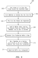
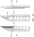
- a method 200 for manufacturing the structural rib 130 may include utilization of a Refractory Metal Core (RMC) or other sacrificial insert.
- RMC Refractory Metal Core
- two halves of a core die are closed around the sacrificial insert (202; FIG. 10 ).
- One half of the core die includes the suction side wall complete with suction side half of trailing edge pedestals, heat transfer features, and axial standoff ribs.
- One half of the die includes the pressure side wall complete with pressure side half of trailing edge pedestals, heat transfer features, and axial standoff ribs.
- the core material is injected into the core die (204).
- the core die halves are separated (206) and the sacrificial insert is melted away (208) which leaves a ceramic core with ceramic ties between the cavities that will form the structural rib 130.
- the ceramic core is then positioned within a shell that defines the outer surface of the airfoil while the core forms the internal surfaces such as that which defines the multiple of axial standoff ribs 110 and the structural rib 130 (210). That is, during the casting process, the core fills a selected volume within the shell that, when removed from the finished casting, defines the array of internal passageways utilized for cooling flow.
- the shell and the core define a mold to cast complex exterior and interior geometries and may be formed of refractory metals, ceramic, or hybrids thereof. The mold thereby operates as a melting unit and/or a die for a desired material that forms the doublet (212).
- the desired material may include but not be limited to a superalloy or other material such as nickel based superalloy, cobalt based superalloy, iron based superalloy, and mixtures thereof.
- the baffle 112 is inserted into the airfoil 100 (214). It should be appreciated that other steps may alternatively or additionally be provided.
- a single crystal starter seed or grain selector may be utilized to enable a single crystal to form when solidifying the component.
- the solidification may utilize a chill block in a directional solidification furnace.
- the directional solidification furnace has a hot zone that may be induction heated and a cold zone separated by an isolation valve.
- the chill block may be elevated into the hot zone and filled with molten super alloy. Casting is typically performed under an inert atmosphere or vacuum to preserve the purity of the casting.
- the vane and/or the baffle may be formed via an additive manufacturing process.
- the additive manufacturing process sequentially builds-up layers of materials that include but are not limited to, various titanium alloys including Ti 6-4, Inconel 625 Alloy, Inconel 718 Alloy, Haynes230 Alloy, stainless steel, tool steel, cobalt chrome, titanium, nickel, aluminum, ceramics, plastics and others in atomized powder material form.
- the starting materials can be non-atomized powders, filled or unfilled resins in liquid, solid or semisolid forms, and wire-based approaches such as wire arc for metals and Fused Deposition Modeling (FDM) for polymers.
- FDM Fused Deposition Modeling
- Alloys such as Inconel 625, Inconel 718 and Haynes 230 may have specific benefit for high temperature environments, such as, for example, environments typically encountered by aerospace and gas turbine engine articles.
- the additive manufacturing processes include, but are not limited to, SFF processes, 3-D printing methods, Sanders Modelmaker, Selective Laser Sintering (SLS), 3D systems thermojet, ZCorp 3D printing Binder jetting, Extrude ProMetal 3D printing, stereolithography, Layered Object Manufacturing (LOM), Fused Deposition Modeling (FDDM), Electron Beam Sintering (EBS), Direct Metal Laser Sintering (DMLS), Electron Beam Melting (EBM), Electron Beam Powder Bed Fusion (EB-PBF), Electron Beam Powder Wire (EBW), Laser Engineered Net Shaping (LENS), Laser Net Shape Manufacturing (LNSM), Direct Metal Deposition (DMD), Laser Powder Bed Fusion (L-PBF), Digital Light SynthesisTM and Continuous Liquid Interface Production (CLIPTM).
- SFF processes 3-D printing
- the geometry provides the stiffness required to prevent airfoil panel bulge while allowing cooling flow to travel axially from the leading edge to trailing edge with minimal pressure loss.
- the embodiments set forth in this application may be applied to other components of the engine, such as blades.
Claims (1)
- Aube de turbine (70) pour un moteur à turbine à gaz (20), comprenant :une plateforme d'aube externe (74) ;une plateforme d'aube interne (72) ;une première paroi latérale (106) ;une première pluralité de nervures d'écartement axiales (110) qui s'étendent depuis la première paroi latérale (106) ;une seconde paroi latérale (108) ;une seconde pluralité de nervures d'écartement axiales (110) qui s'étendent depuis la seconde paroi latérale (108) ; etune nervure structurale (130) qui s'étend entre la première pluralité de nervures d'écartement axiales (110) et la seconde pluralité de nervures d'écartement axiales (110),dans laquelle la première paroi latérale (106) est un intrados (106) et la seconde paroi latérale (108) est un extrados (108) d'un profil aérodynamique (100), dans laquelle la première paroi latérale (106) et la seconde paroi latérale (108) s'étendent entre la plateforme d'aube externe (74) et la plateforme d'aube interne (72),dans laquelle la nervure structurale (130) s'étend entre la plateforme d'aube externe (74) et la plateforme d'aube interne (72), caractérisée en ce que l'aube (70) comprend en outre un déflecteur (112) comportant une section de déflecteur avant (112A) adjacente à la nervure structurale (130) et une section de déflecteur arrière (112B) adjacente à la nervure structurale (130),dans laquelle chacune de la première pluralité de nervures d'écartement axiales (110) rencontre l'une de la seconde pluralité de nervures d'écartement axiales (110) au niveau d'un bord d'attaque (102),dans laquelle chacune de la première pluralité de nervures d'écartement axiales (110) et chacune de la seconde pluralité de nervures d'écartement axiales (110) s'étend en avant d'une pluralité d'ouvertures de bord de fuite (120),dans laquelle la nervure structurale (130) ne s'étend pas complètement entre la première paroi latérale (106) et la seconde paroi latérale (108) et est reliée aux première et seconde pluralités de nervures d'écartement axiales (110) mais pas à la première paroi latérale (106) et à la seconde paroi latérale (108),dans laquelle la nervure structurale (130) et les première et seconde pluralités de nervures d'écartement axiales (110) forment une pluralité de passages axiaux (116),dans laquelle la pluralité de passages axiaux (116) s'étendent entre chacune de la pluralité de nervures d'écartement axiales (110),dans laquelle chacun de la pluralité de passages axiaux (116) est défini entre un déflecteur (112), la nervure structurale (130), la pluralité de nervures d'écartement axiales (110) et les première et seconde parois latérales respectives (106, 108), dans laquelle l'aube (70) comprend en outre des ouvertures (114) dans un bord d'attaque (102) du déflecteur (112) configurées pour éjecter de l'air de refroidissement du déflecteur (112).
Applications Claiming Priority (1)
| Application Number | Priority Date | Filing Date | Title |
|---|---|---|---|
| US16/210,606 US20200182068A1 (en) | 2018-12-05 | 2018-12-05 | Axial flow cooling scheme with structural rib for a gas turbine engine |
Publications (2)
| Publication Number | Publication Date |
|---|---|
| EP3663524A1 EP3663524A1 (fr) | 2020-06-10 |
| EP3663524B1 true EP3663524B1 (fr) | 2021-08-25 |
Family
ID=68808072
Family Applications (1)
| Application Number | Title | Priority Date | Filing Date |
|---|---|---|---|
| EP19213966.5A Active EP3663524B1 (fr) | 2018-12-05 | 2019-12-05 | Schéma de refroidissement à flux axial avec nervure structurale pour un moteur à turbine à gaz |
Country Status (2)
| Country | Link |
|---|---|
| US (1) | US20200182068A1 (fr) |
| EP (1) | EP3663524B1 (fr) |
Families Citing this family (2)
| Publication number | Priority date | Publication date | Assignee | Title |
|---|---|---|---|---|
| US11021966B2 (en) * | 2019-04-24 | 2021-06-01 | Raytheon Technologies Corporation | Vane core assemblies and methods |
| US11230931B1 (en) * | 2020-07-03 | 2022-01-25 | Raytheon Technologies Corporation | Inserts for airfoils of gas turbine engines |
Family Cites Families (11)
| Publication number | Priority date | Publication date | Assignee | Title |
|---|---|---|---|---|
| GB1034260A (en) * | 1964-12-02 | 1966-06-29 | Rolls Royce | Aerofoil-shaped blade for use in a fluid flow machine |
| BE755567A (fr) * | 1969-12-01 | 1971-02-15 | Gen Electric | Structure d'aube fixe, pour moteur a turbines a gaz et arrangement de reglage de temperature associe |
| GB1304678A (fr) * | 1971-06-30 | 1973-01-24 | ||
| JPS61118501A (ja) * | 1984-11-15 | 1986-06-05 | Toshiba Corp | ガスタ−ビンの羽根 |
| US5511937A (en) * | 1994-09-30 | 1996-04-30 | Westinghouse Electric Corporation | Gas turbine airfoil with a cooling air regulating seal |
| EP1136651A1 (fr) * | 2000-03-22 | 2001-09-26 | Siemens Aktiengesellschaft | Système de refroidissement pour une aube de turbine à gaz |
| US6428273B1 (en) * | 2001-01-05 | 2002-08-06 | General Electric Company | Truncated rib turbine nozzle |
| US8210814B2 (en) * | 2008-06-18 | 2012-07-03 | General Electric Company | Crossflow turbine airfoil |
| US8348613B2 (en) * | 2009-03-30 | 2013-01-08 | United Technologies Corporation | Airflow influencing airfoil feature array |
| US10253634B2 (en) * | 2013-06-04 | 2019-04-09 | United Technologies Corporation | Gas turbine engine airfoil trailing edge suction side cooling |
| US10648341B2 (en) * | 2016-11-15 | 2020-05-12 | Rolls-Royce Corporation | Airfoil leading edge impingement cooling |
-
2018
- 2018-12-05 US US16/210,606 patent/US20200182068A1/en not_active Abandoned
-
2019
- 2019-12-05 EP EP19213966.5A patent/EP3663524B1/fr active Active
Also Published As
| Publication number | Publication date |
|---|---|
| US20200182068A1 (en) | 2020-06-11 |
| EP3663524A1 (fr) | 2020-06-10 |
Similar Documents
| Publication | Publication Date | Title |
|---|---|---|
| US11059093B2 (en) | Additively manufactured core for use in casting an internal cooling circuit of a gas turbine engine component | |
| EP2947184B1 (fr) | Procédé permettant de former des composants à l'aide de refonte et de fabrication additive | |
| US9770758B2 (en) | Method for forming a directionally solidified replacement body for a component using additive manufacturing | |
| EP3663525B1 (fr) | Schéma de refroidissement à flux axial avec nervure structurale pouvant être moulée pour un moteur à turbine à gaz | |
| EP2708296B1 (fr) | Procédés de fabrication d'ensembles de surfaces portantes de stator de turbine par méthodes de fabrication additive | |
| EP3012436B1 (fr) | Système d'échangeur de chaleur canalisé fabriqué de manière additive | |
| US11236621B2 (en) | Method for forming single crystal components using additive manufacturing and re-melt | |
| US9718127B2 (en) | Method for forming components using additive manufacturing and re-melt | |
| US10247015B2 (en) | Cooled blisk with dual wall blades for gas turbine engine | |
| EP3184200A1 (fr) | Noyau de fabrication additive destiné à être utilisé dans le moulage d'un circuit de refroidissement interne d'un composant de turbomachine | |
| US20210047932A1 (en) | Airfoil with tunable cooling configuration | |
| EP2719509A2 (fr) | Procédé de fabrication de canaux de refroidissement de surface sur un composant à l'aide de techniques de moulage lithographique | |
| EP3663524B1 (fr) | Schéma de refroidissement à flux axial avec nervure structurale pour un moteur à turbine à gaz | |
| CN115217798A (zh) | 分体式壳体以及形成和冷却壳体的方法 |
Legal Events
| Date | Code | Title | Description |
|---|---|---|---|
| PUAI | Public reference made under article 153(3) epc to a published international application that has entered the european phase |
Free format text: ORIGINAL CODE: 0009012 |
|
| STAA | Information on the status of an ep patent application or granted ep patent |
Free format text: STATUS: THE APPLICATION HAS BEEN PUBLISHED |
|
| AK | Designated contracting states |
Kind code of ref document: A1 Designated state(s): AL AT BE BG CH CY CZ DE DK EE ES FI FR GB GR HR HU IE IS IT LI LT LU LV MC MK MT NL NO PL PT RO RS SE SI SK SM TR |
|
| AX | Request for extension of the european patent |
Extension state: BA ME |
|
| STAA | Information on the status of an ep patent application or granted ep patent |
Free format text: STATUS: REQUEST FOR EXAMINATION WAS MADE |
|
| 17P | Request for examination filed |
Effective date: 20201210 |
|
| RBV | Designated contracting states (corrected) |
Designated state(s): AL AT BE BG CH CY CZ DE DK EE ES FI FR GB GR HR HU IE IS IT LI LT LU LV MC MK MT NL NO PL PT RO RS SE SI SK SM TR |
|
| GRAP | Despatch of communication of intention to grant a patent |
Free format text: ORIGINAL CODE: EPIDOSNIGR1 |
|
| STAA | Information on the status of an ep patent application or granted ep patent |
Free format text: STATUS: GRANT OF PATENT IS INTENDED |
|
| RIC1 | Information provided on ipc code assigned before grant |
Ipc: F01D 9/02 20060101ALI20210129BHEP Ipc: F01D 5/18 20060101AFI20210129BHEP |
|
| RAP1 | Party data changed (applicant data changed or rights of an application transferred) |
Owner name: RAYTHEON TECHNOLOGIES CORPORATION |
|
| INTG | Intention to grant announced |
Effective date: 20210310 |
|
| GRAS | Grant fee paid |
Free format text: ORIGINAL CODE: EPIDOSNIGR3 |
|
| GRAA | (expected) grant |
Free format text: ORIGINAL CODE: 0009210 |
|
| STAA | Information on the status of an ep patent application or granted ep patent |
Free format text: STATUS: THE PATENT HAS BEEN GRANTED |
|
| AK | Designated contracting states |
Kind code of ref document: B1 Designated state(s): AL AT BE BG CH CY CZ DE DK EE ES FI FR GB GR HR HU IE IS IT LI LT LU LV MC MK MT NL NO PL PT RO RS SE SI SK SM TR |
|
| REG | Reference to a national code |
Ref country code: CH Ref legal event code: EP |
|
| REG | Reference to a national code |
Ref country code: IE Ref legal event code: FG4D Ref country code: AT Ref legal event code: REF Ref document number: 1423986 Country of ref document: AT Kind code of ref document: T Effective date: 20210915 |
|
| REG | Reference to a national code |
Ref country code: DE Ref legal event code: R096 Ref document number: 602019007174 Country of ref document: DE |
|
| REG | Reference to a national code |
Ref country code: LT Ref legal event code: MG9D |
|
| REG | Reference to a national code |
Ref country code: NL Ref legal event code: MP Effective date: 20210825 |
|
| REG | Reference to a national code |
Ref country code: AT Ref legal event code: MK05 Ref document number: 1423986 Country of ref document: AT Kind code of ref document: T Effective date: 20210825 |
|
| PG25 | Lapsed in a contracting state [announced via postgrant information from national office to epo] |
Ref country code: RS Free format text: LAPSE BECAUSE OF FAILURE TO SUBMIT A TRANSLATION OF THE DESCRIPTION OR TO PAY THE FEE WITHIN THE PRESCRIBED TIME-LIMIT Effective date: 20210825 Ref country code: SE Free format text: LAPSE BECAUSE OF FAILURE TO SUBMIT A TRANSLATION OF THE DESCRIPTION OR TO PAY THE FEE WITHIN THE PRESCRIBED TIME-LIMIT Effective date: 20210825 Ref country code: ES Free format text: LAPSE BECAUSE OF FAILURE TO SUBMIT A TRANSLATION OF THE DESCRIPTION OR TO PAY THE FEE WITHIN THE PRESCRIBED TIME-LIMIT Effective date: 20210825 Ref country code: PT Free format text: LAPSE BECAUSE OF FAILURE TO SUBMIT A TRANSLATION OF THE DESCRIPTION OR TO PAY THE FEE WITHIN THE PRESCRIBED TIME-LIMIT Effective date: 20211227 Ref country code: NO Free format text: LAPSE BECAUSE OF FAILURE TO SUBMIT A TRANSLATION OF THE DESCRIPTION OR TO PAY THE FEE WITHIN THE PRESCRIBED TIME-LIMIT Effective date: 20211125 Ref country code: HR Free format text: LAPSE BECAUSE OF FAILURE TO SUBMIT A TRANSLATION OF THE DESCRIPTION OR TO PAY THE FEE WITHIN THE PRESCRIBED TIME-LIMIT Effective date: 20210825 Ref country code: FI Free format text: LAPSE BECAUSE OF FAILURE TO SUBMIT A TRANSLATION OF THE DESCRIPTION OR TO PAY THE FEE WITHIN THE PRESCRIBED TIME-LIMIT Effective date: 20210825 Ref country code: AT Free format text: LAPSE BECAUSE OF FAILURE TO SUBMIT A TRANSLATION OF THE DESCRIPTION OR TO PAY THE FEE WITHIN THE PRESCRIBED TIME-LIMIT Effective date: 20210825 Ref country code: BG Free format text: LAPSE BECAUSE OF FAILURE TO SUBMIT A TRANSLATION OF THE DESCRIPTION OR TO PAY THE FEE WITHIN THE PRESCRIBED TIME-LIMIT Effective date: 20211125 Ref country code: LT Free format text: LAPSE BECAUSE OF FAILURE TO SUBMIT A TRANSLATION OF THE DESCRIPTION OR TO PAY THE FEE WITHIN THE PRESCRIBED TIME-LIMIT Effective date: 20210825 |
|
| PG25 | Lapsed in a contracting state [announced via postgrant information from national office to epo] |
Ref country code: PL Free format text: LAPSE BECAUSE OF FAILURE TO SUBMIT A TRANSLATION OF THE DESCRIPTION OR TO PAY THE FEE WITHIN THE PRESCRIBED TIME-LIMIT Effective date: 20210825 Ref country code: LV Free format text: LAPSE BECAUSE OF FAILURE TO SUBMIT A TRANSLATION OF THE DESCRIPTION OR TO PAY THE FEE WITHIN THE PRESCRIBED TIME-LIMIT Effective date: 20210825 Ref country code: GR Free format text: LAPSE BECAUSE OF FAILURE TO SUBMIT A TRANSLATION OF THE DESCRIPTION OR TO PAY THE FEE WITHIN THE PRESCRIBED TIME-LIMIT Effective date: 20211126 |
|
| PG25 | Lapsed in a contracting state [announced via postgrant information from national office to epo] |
Ref country code: NL Free format text: LAPSE BECAUSE OF FAILURE TO SUBMIT A TRANSLATION OF THE DESCRIPTION OR TO PAY THE FEE WITHIN THE PRESCRIBED TIME-LIMIT Effective date: 20210825 |
|
| PG25 | Lapsed in a contracting state [announced via postgrant information from national office to epo] |
Ref country code: DK Free format text: LAPSE BECAUSE OF FAILURE TO SUBMIT A TRANSLATION OF THE DESCRIPTION OR TO PAY THE FEE WITHIN THE PRESCRIBED TIME-LIMIT Effective date: 20210825 |
|
| REG | Reference to a national code |
Ref country code: DE Ref legal event code: R097 Ref document number: 602019007174 Country of ref document: DE |
|
| PG25 | Lapsed in a contracting state [announced via postgrant information from national office to epo] |
Ref country code: SM Free format text: LAPSE BECAUSE OF FAILURE TO SUBMIT A TRANSLATION OF THE DESCRIPTION OR TO PAY THE FEE WITHIN THE PRESCRIBED TIME-LIMIT Effective date: 20210825 Ref country code: SK Free format text: LAPSE BECAUSE OF FAILURE TO SUBMIT A TRANSLATION OF THE DESCRIPTION OR TO PAY THE FEE WITHIN THE PRESCRIBED TIME-LIMIT Effective date: 20210825 Ref country code: RO Free format text: LAPSE BECAUSE OF FAILURE TO SUBMIT A TRANSLATION OF THE DESCRIPTION OR TO PAY THE FEE WITHIN THE PRESCRIBED TIME-LIMIT Effective date: 20210825 Ref country code: EE Free format text: LAPSE BECAUSE OF FAILURE TO SUBMIT A TRANSLATION OF THE DESCRIPTION OR TO PAY THE FEE WITHIN THE PRESCRIBED TIME-LIMIT Effective date: 20210825 Ref country code: CZ Free format text: LAPSE BECAUSE OF FAILURE TO SUBMIT A TRANSLATION OF THE DESCRIPTION OR TO PAY THE FEE WITHIN THE PRESCRIBED TIME-LIMIT Effective date: 20210825 Ref country code: AL Free format text: LAPSE BECAUSE OF FAILURE TO SUBMIT A TRANSLATION OF THE DESCRIPTION OR TO PAY THE FEE WITHIN THE PRESCRIBED TIME-LIMIT Effective date: 20210825 |
|
| PLBE | No opposition filed within time limit |
Free format text: ORIGINAL CODE: 0009261 |
|
| STAA | Information on the status of an ep patent application or granted ep patent |
Free format text: STATUS: NO OPPOSITION FILED WITHIN TIME LIMIT |
|
| PG25 | Lapsed in a contracting state [announced via postgrant information from national office to epo] |
Ref country code: MC Free format text: LAPSE BECAUSE OF FAILURE TO SUBMIT A TRANSLATION OF THE DESCRIPTION OR TO PAY THE FEE WITHIN THE PRESCRIBED TIME-LIMIT Effective date: 20210825 Ref country code: IT Free format text: LAPSE BECAUSE OF FAILURE TO SUBMIT A TRANSLATION OF THE DESCRIPTION OR TO PAY THE FEE WITHIN THE PRESCRIBED TIME-LIMIT Effective date: 20210825 |
|
| 26N | No opposition filed |
Effective date: 20220527 |
|
| PG25 | Lapsed in a contracting state [announced via postgrant information from national office to epo] |
Ref country code: SI Free format text: LAPSE BECAUSE OF FAILURE TO SUBMIT A TRANSLATION OF THE DESCRIPTION OR TO PAY THE FEE WITHIN THE PRESCRIBED TIME-LIMIT Effective date: 20210825 |
|
| REG | Reference to a national code |
Ref country code: BE Ref legal event code: MM Effective date: 20211231 |
|
| PG25 | Lapsed in a contracting state [announced via postgrant information from national office to epo] |
Ref country code: LU Free format text: LAPSE BECAUSE OF NON-PAYMENT OF DUE FEES Effective date: 20211205 Ref country code: IE Free format text: LAPSE BECAUSE OF NON-PAYMENT OF DUE FEES Effective date: 20211205 |
|
| PG25 | Lapsed in a contracting state [announced via postgrant information from national office to epo] |
Ref country code: BE Free format text: LAPSE BECAUSE OF NON-PAYMENT OF DUE FEES Effective date: 20211231 |
|
| P01 | Opt-out of the competence of the unified patent court (upc) registered |
Effective date: 20230521 |
|
| PG25 | Lapsed in a contracting state [announced via postgrant information from national office to epo] |
Ref country code: CY Free format text: LAPSE BECAUSE OF FAILURE TO SUBMIT A TRANSLATION OF THE DESCRIPTION OR TO PAY THE FEE WITHIN THE PRESCRIBED TIME-LIMIT Effective date: 20210825 |
|
| PG25 | Lapsed in a contracting state [announced via postgrant information from national office to epo] |
Ref country code: HU Free format text: LAPSE BECAUSE OF FAILURE TO SUBMIT A TRANSLATION OF THE DESCRIPTION OR TO PAY THE FEE WITHIN THE PRESCRIBED TIME-LIMIT; INVALID AB INITIO Effective date: 20191205 |
|
| REG | Reference to a national code |
Ref country code: CH Ref legal event code: PL |
|
| PG25 | Lapsed in a contracting state [announced via postgrant information from national office to epo] |
Ref country code: LI Free format text: LAPSE BECAUSE OF NON-PAYMENT OF DUE FEES Effective date: 20221231 Ref country code: CH Free format text: LAPSE BECAUSE OF NON-PAYMENT OF DUE FEES Effective date: 20221231 |
|
| PGFP | Annual fee paid to national office [announced via postgrant information from national office to epo] |
Ref country code: GB Payment date: 20231121 Year of fee payment: 5 |
|
| PGFP | Annual fee paid to national office [announced via postgrant information from national office to epo] |
Ref country code: FR Payment date: 20231122 Year of fee payment: 5 Ref country code: DE Payment date: 20231121 Year of fee payment: 5 |