EP3663500A1 - Locking fitting for adjacent frame construction parts - Google Patents
Locking fitting for adjacent frame construction parts Download PDFInfo
- Publication number
- EP3663500A1 EP3663500A1 EP19207348.4A EP19207348A EP3663500A1 EP 3663500 A1 EP3663500 A1 EP 3663500A1 EP 19207348 A EP19207348 A EP 19207348A EP 3663500 A1 EP3663500 A1 EP 3663500A1
- Authority
- EP
- European Patent Office
- Prior art keywords
- inner part
- locking
- bolt body
- rotary
- rotary bolt
- Prior art date
- Legal status (The legal status is an assumption and is not a legal conclusion. Google has not performed a legal analysis and makes no representation as to the accuracy of the status listed.)
- Granted
Links
- 238000010276 construction Methods 0.000 title claims abstract description 9
- 230000002093 peripheral effect Effects 0.000 claims abstract 2
- XEEYBQQBJWHFJM-UHFFFAOYSA-N Iron Chemical compound [Fe] XEEYBQQBJWHFJM-UHFFFAOYSA-N 0.000 claims description 10
- 238000005520 cutting process Methods 0.000 claims description 6
- 239000000463 material Substances 0.000 claims description 6
- 229910052742 iron Inorganic materials 0.000 claims description 5
- 229910000746 Structural steel Inorganic materials 0.000 claims description 4
- 229910000831 Steel Inorganic materials 0.000 claims description 2
- 238000003698 laser cutting Methods 0.000 claims description 2
- 239000010959 steel Substances 0.000 claims description 2
- 230000015572 biosynthetic process Effects 0.000 claims 1
- 239000002184 metal Substances 0.000 claims 1
- 229910052751 metal Inorganic materials 0.000 claims 1
- 238000004519 manufacturing process Methods 0.000 description 2
- 230000006735 deficit Effects 0.000 description 1
- 238000011161 development Methods 0.000 description 1
- 230000018109 developmental process Effects 0.000 description 1
- 238000005516 engineering process Methods 0.000 description 1
- 238000000034 method Methods 0.000 description 1
- 230000000149 penetrating effect Effects 0.000 description 1
- 238000004080 punching Methods 0.000 description 1
- 230000002441 reversible effect Effects 0.000 description 1
- 230000000007 visual effect Effects 0.000 description 1
Images

Classifications
-
- E—FIXED CONSTRUCTIONS
- E06—DOORS, WINDOWS, SHUTTERS, OR ROLLER BLINDS IN GENERAL; LADDERS
- E06B—FIXED OR MOVABLE CLOSURES FOR OPENINGS IN BUILDINGS, VEHICLES, FENCES OR LIKE ENCLOSURES IN GENERAL, e.g. DOORS, WINDOWS, BLINDS, GATES
- E06B3/00—Window sashes, door leaves, or like elements for closing wall or like openings; Layout of fixed or moving closures, e.g. windows in wall or like openings; Features of rigidly-mounted outer frames relating to the mounting of wing frames
- E06B3/96—Corner joints or edge joints for windows, doors, or the like frames or wings
- E06B3/964—Corner joints or edge joints for windows, doors, or the like frames or wings using separate connection pieces, e.g. T-connection pieces
- E06B3/968—Corner joints or edge joints for windows, doors, or the like frames or wings using separate connection pieces, e.g. T-connection pieces characterised by the way the connecting pieces are fixed in or on the frame members
- E06B3/972—Corner joints or edge joints for windows, doors, or the like frames or wings using separate connection pieces, e.g. T-connection pieces characterised by the way the connecting pieces are fixed in or on the frame members by increasing the cross-section of the connecting pieces, e.g. by expanding the connecting pieces with wedges
- E06B3/9725—Mitre joints
Definitions
- the invention relates to a locking fitting for adjacent frame construction parts with the features specified in the preamble of claim 1.
- the subject of the invention is intended to be used universally as a fitting part for connecting, for example, profile parts in window, door or other frames serving for purposes such as, for example, building up sight and wind protection elements.
- corner connectors are usually used, which are inserted into corresponding longitudinal guides of profile parts to be connected and fixed there in a suitable manner, for example by means of clamping screws, clamping wedges or similar construction elements.
- corner connectors with the features specified in the preamble of claim 1 are in the DE 10 2014 016 508 , EP 3 284 893 A1 or EP 3 121 363 B1 specified.
- the rotary locking element of the locking fitting itself is very simple to cut out from the material of the inner part, for example by punching, but preferably, for example, by laser cutting a flat iron.
- This cutting technique which is now very common, enables very fine and filigree cutting contours, which are ideally suited for the design of the locking element.
- Another advantage of the locking fitting according to the invention lies in the fact that due to the design of the rotary locking element in one piece with the inner part, the latter is held captively on the inner part by means of the retaining web. In connection with the recess in the inner part surrounding it, this holding web has additional functions in accordance with preferred developments of the subject matter of the invention. So it acts together with an angular shape of the recess as a limitation of the angle of rotation of the rotary bolt body.
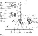
- the Fig. 1 shows the inner part 1 as the first structural part of a locking device, such as that used as a connector for a frame 2 Fig. 4 is shown as a whole.
- This inner part 1 is produced as a flat iron, which is angled in plan view, from a sheet steel part with a rectangular cross section.
- the two legs 4.1, 4.2 of the flat iron can not only at a right angle, but practically at any angle be arranged to each other, for example to form triangular frames.
- the rotary bolt body 6 On the side of the rotary bolt body 6 facing away from the eccentric surface 8, the latter is connected in one piece to the inner part 1 via a retaining web 9 which is inclined to the radial direction, the retaining web 9 extending parallel to the edge 13a of a recess 10 which widens angularly towards the rotary bolt body 6.
- the locking bar body 6 is provided centrally with an internal hexagon 11 for the engagement of a hexagon key for the rotary actuation of the locking bar body 6.
- Recognizable deformation of the retaining web 9 is simulated a kind of over-center kinematics, which on the one hand ensures that the rotary bolt body 6 is pressed particularly strongly beyond the inner edges 3 and in its 2 and 3 locked position shown is fixed. Basically, by rotating the rotary bolt body 6 against the in Fig. 1 and 2nd Directional arrows shown DR the locking reversible.
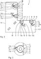
- a miter-cut frame profile for example a stable frame for a privacy and wind protection element, is pushed onto the two legs 4.1, 4.2 of the inner part 1 as outer parts 14.
- These outer parts 14 flank the inner part 1 in the area of its flat rectangular cross section, in that the outer parts 14 with shape-adapted guide grooves 15 encompass the outer edges 16 and inner edges 3 facing away from one another.
- Fig. 4 and 6 it becomes clear that the rotary bolt bodies 6 with their hexagon receptacles 11 are still accessible and - as explained above - can be operated in rotation and thus into the 2 to 6 locking position shown are transferred.
- the rotary bolt bodies 6 act with their flanks 12 on the outer parts 14 in the one guide groove 15 and thus form a stable connection between the two outer parts 14.
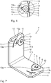
- FIG. 7 An alternative inner part 1 'is shown, which is designed as a corner connector angle iron with legs 17.1, 17.2 arranged in two mutually perpendicular planes.
- the two legs 17.1, 17.2 can also be oriented at a different, practically arbitrary angle to one another.
- each turn bar elements 5 are formed adjacent to the side edges 18.
- Outer parts (not shown) plugged onto it as profiles for the production of a frame are to be connected stably in the manner explained above.
Abstract
Ein Verriegelungsbeschlag für aneinander grenzende Rahmen-Konstruktionsteile, umfasst- ein Innenteil (1, 1') als erstes Konstruktionsteil mit einem zumindest abschnittsweise flach-rechteckigen Querschnitt,- ein Außenteil als zweites Konstruktionsteil, das das Innenteil (1, 1') im Bereich seines flach-rechteckigen Querschnittes flankiert, und- mindestens ein im Bereich des flach-rechteckigen Querschnittes des Innenteils (1, 1') ausgeschnittenes Drehriegelelement (5) mit= einem scheibenförmigen, in einer runden Führungskontur (7) des Innenteiles (1, 1') drehbar geführten, an die das Außenteil (14) flankierende Seitenfläche (3) des Innenteils (1, 1') angrenzenden Drehriegelkörper (6),= einer an einem Umfangsabschnitt des Drehriegelkörpers (6) angelegte Exzenterfläche (8), die in der entriegelten Stellung des Drehriegelkörpers (6) mit der flankierenden Seitenflächen (3) des Innenkörpers (1, 1') fluchtet und in der verriegelten Stellung sich in die Führungskontur (7) des Innenteiles (1, 1') derart verlagert, dass der Drehriegelkörper (6) mit seiner der Exzenterfläche (8) benachbarten Flanke (12) das Außenteil (14) verriegelnd beaufschlagt, sowie= einem Haltesteg (9) zwischen Drehriegelkörper (6) und Innenteil (1, 1').A locking fitting for adjoining frame construction parts comprises - an inner part (1, 1 ') as the first construction part with an at least partially flat-rectangular cross-section, - an outer part as a second construction part, which the inner part (1, 1') in the area of it flanked with a rectangular cross-section, and - at least one rotary locking element (5) cut out in the region of the flat-rectangular cross-section of the inner part (1, 1 ') with = a disk-shaped, in a round guide contour (7) of the inner part (1, 1') rotatably guided, to the outer part (14) flanking side surface (3) of the inner part (1, 1 ') adjacent rotary bolt body (6) = an eccentric surface (8) applied to a peripheral portion of the rotary bolt body (6), which in the unlocked position of the rotary bolt body (6) is flush with the flanking side surfaces (3) of the inner body (1, 1 ') and in the locked position fits into the guide contour (7) of the inner part (1, 1') displaced in such a way that the flank (6) with its flank (12) adjacent to the eccentric surface (8) acts on the outer part (14) in a locking manner, and = a retaining web (9) between the flap body (6) and the inner part (1, 1 ').
Description
Die vorliegende Patentanmeldung nimmt die Priorität der deutschen Patentanmeldung
Die Erfindung betrifft einen Verriegelungsbeschlag für aneinander grenzende Rahmenkonstruktionsteile mit den im Oberbegriff des Anspruchs 1 angegebenen Merkmalen.The invention relates to a locking fitting for adjacent frame construction parts with the features specified in the preamble of
Der Erfindungsgegenstand soll dabei universell als Beschlagteil zur Verbindung beispielsweise von Profilteilen bei Fenster-, Tür- oder für andere Zwecke dienenden Rahmen, wie beispielsweise zum Aufbau von Sicht- und Windschutz-Elementen verwendet werden.The subject of the invention is intended to be used universally as a fitting part for connecting, for example, profile parts in window, door or other frames serving for purposes such as, for example, building up sight and wind protection elements.
Hierfür werden üblicherweise Eckverbinder eingesetzt, die in entsprechende Längsführungen von zu verbindenden Profilteilen eingeschoben und dort in geeigneter Weise, beispielsweise durch Klemmschrauben, Klemmkeile oder ähnliche Konstruktionselemente festgelegt werden. Beispiele für solche Eckverbinder mit den im Oberbegriff des Anspruches 1 angegebenen Merkmalen sind in der
Problematisch bei diesen üblichen Beschlagteilen ist die Tatsache, dass die Konstruktionselemente gesonderte Teile sind, für die spezielle Verbindungen, wie Gewinde, an den Beschlagteilen hergestellt werden müssen. Darüber hinaus ist deren Montagetechnik selbst oft aufwendig und - weil die gesonderten Konstruktionselemente verlierbare Einzelteile sind - oft mühselig. Auch werden solche Beschlagteile oft direkt in die zu verbindenden Rahmenteile eingeschraubt, was zu Beeinträchtigungen daran führen kann.The problem with these conventional fitting parts is the fact that the construction elements are separate parts for which special connections, such as threads, have to be produced on the fitting parts. In addition, their assembly technology itself is often complex and - because the separate construction elements are lost parts - often cumbersome. Such fittings are often screwed directly into the frame parts to be connected, which can lead to impairments.
Grundsätzlich besteht also bei solchen als Massenware in großen Stückzahlen eingesetzten Beschlagteilen das Bedürfnis für einen extrem einfach herzustellenden, rationell zu montierenden und dabei im Endmontagezustand sehr stabilen Verriegelungsbeschlag.Basically, there is therefore a need for an extremely simple to manufacture, Lock fitting that is efficient to install and very stable in the final assembly state.
Diese Aufgabe wird laut Anspruch 1 durch einen Verriegelungsbeschlag gelöst, der umfasst
- ein Innenteil als erstes Konstruktionsteil mit einem zumindest abschnittsweise flachrechteckigen Querschnitt, und
- ein Außenteil als zweites Konstruktionsteil, das das Innenteil im Bereich seines flachrechteckigen Querschnittes flankiert, sowie
- mindestens ein im Bereich des flachrechteckigen Querschnittes des Innenteils aus dessen Material durch eine vertikal durchgehende Schnittkontur ausgeschnittenes, damit einstückig ausgeführtes Drehriegelelement, das aufweist
- = einen scheibenförmigen, in einer runden Führungskontur des Innenteiles drehbar geführten, an die das Außenteil flankierende Seitenfläche des Innenteils angrenzenden Drehriegelkörper,
- = eine an einem Umfangsabschnitt des Drehriegelkörpers angelegte, zurückspringende Exzenterfläche, die in der entriegelten Stellung des Drehriegelkörpers mit der flankierenden Seitenflächen des Innenkörpers im Wesentlichen fluchtet und in der durch eine Drehung des Drehriegelkörpers verriegelten Stellung des Drehriegelkörpers sich in die Führungskontur des Innenteiles derart verlagert, dass der Drehriegelkörper mit seiner der Exzenterfläche benachbarten Flanke das Außenteil verriegelnd beaufschlagt, sowie
- = einen eine Aussparung im Innenteil überbrückenden Haltesteg zwischen Drehriegelkörper und Innenteil.
- an inner part as a first structural part with a flat rectangular cross-section at least in sections, and
- an outer part as a second structural part, which flanks the inner part in the area of its flat rectangular cross section, and
- At least one in the area of the flat rectangular cross-section of the inner part, which is cut out of its material by a vertically continuous cutting contour and is therefore made in one piece, which has
- = a disk-shaped rotary bolt body, which is rotatably guided in a round guide contour of the inner part and adjoins the side surface of the inner part flanking the outer part,
- = a recessed eccentric surface applied to a circumferential section of the rotary bolt body, which in the unlocked position of the rotary bolt body is essentially flush with the flanking side surfaces of the inner body and in the position of the rotary bolt body locked by rotation of the rotary bolt body moves into the guide contour of the inner part such that the rotary bolt body with its flank adjacent to the eccentric surface acts on the outer part in a locking manner, and
- = a retaining bridge bridging a recess in the inner part between the rotary bolt body and the inner part.
Einer der Hauptvorteile dieser erfindungsgemäßen Ausgestaltung liegt darin, dass das Drehriegelelement des Verriegelungsbeschlages durch das Ausschneiden aus dem Material des Innenteils selbst sehr einfach, beispielsweise durch Stanzen, bevorzugterweise jedoch etwa durch Laserschneiden aus einem Flacheisen, hergestellt werden kann. Diese mittlerweile sehr übliche Schneidetechnik ermöglicht sehr feine und filigrane Schnittkonturen, die für die Ausbildung des Drehriegelelementes bestens geeignet sind.One of the main advantages of this configuration according to the invention is that the rotary locking element of the locking fitting itself is very simple to cut out from the material of the inner part, for example by punching, but preferably, for example, by laser cutting a flat iron. This cutting technique, which is now very common, enables very fine and filigree cutting contours, which are ideally suited for the design of the locking element.
Ein weiterer Vorteil des erfindungsgemäßen Verriegelungsbeschlages liegt in der Tatsache, dass durch die mit dem Innenteil einstückige Ausbildung des Drehriegelelementes dieses mithilfe des Haltesteges unverlierbar am Innenteil gehalten ist. Dieser Haltesteg hat in Verbindung mit der ihn umgebenden Aussparung im Innenteil gemäß bevorzugten Weiterbildungen des Erfindungsgegenstandes noch zusätzliche Funktionen. So wirkt er zusammen mit einer Winkelform der Aussparung als Begrenzung des Drehwinkels des Drehriegelkörpers. Darüber hinaus bildet er bei seiner Deformation während der Drehung des Drehriegelkörper die Funktion eines KniehebelMechanismus nach, die zum einen für eine zusätzliche Fixierung des Drehriegelkörpers in der verriegelten Übertotpunktstellung und zum anderen für ein zusätzliche Beaufschlagung des Drehriegelkörpers in Richtung zum festzulegenden Außenteil sorgt.Another advantage of the locking fitting according to the invention lies in the fact that due to the design of the rotary locking element in one piece with the inner part, the latter is held captively on the inner part by means of the retaining web. In connection with the recess in the inner part surrounding it, this holding web has additional functions in accordance with preferred developments of the subject matter of the invention. So it acts together with an angular shape of the recess as a limitation of the angle of rotation of the rotary bolt body. In addition, when it is deformed during the rotation of the rotary bolt body, it simulates the function of a toggle lever mechanism, which on the one hand provides additional fixation of the rotary bolt body in the locked over-center position and on the other hand provides additional loading of the rotary bolt body in the direction of the outer part to be fixed.
Schließlich sorgt die nach Art eines Exzenters wirkende Verriegelung zwischen Innen- und Außenteil für eine sehr stabile Verbindung zwischen diesen beiden Bauteilen.Finally, the eccentric locking mechanism between the inner and outer part ensures a very stable connection between these two components.
Zur Vermeidung unnötiger Wiederholungen wird bezüglich der Erläuterung weiterer Merkmale, Einzelheiten, Vorteile und bevorzugter Ausführungsformen auf die nachfolgende Beschreibung von Ausführungsbeispielen der Erfindung anhand der beigefügten Zeichnungen verwiesen. Darin zeigen:
- Fig. 1
- eine Draufsicht auf ein als Flacheisen ausgebildetes Innenteil einer Verriegelungsvorrichtung in entriegelter Stellung,
- Fig. 2
- eine Draufsicht analog
Fig. 1 in verriegelter Stellung der Verriegelungsvorrichtung, - Fig. 3
- eine vergrößerte, ausschnittsweise Draufsicht der Einzelheit III aus
Fig. 2 , - Fig. 4
- eine ausschnittsweise Draufsicht auf den Eckbereich eines Rahmens mit einer Verriegelungsvorrichtung in verriegelter Stellung,
- Fig. 5
- einen Querschnitt des Rahmens entlang der Schnittlinie V-V nach
Fig. 4 , - Fig. 6
- eine vergrößerte, ausschnittsweise Draufsicht der Einzelheit VI aus
Figur 5 - Fig. 7
- eine perspektivische Ansicht eines als Winkeleisen ausgebildeten Innenteils einer Verriegelungsvorrichtung in entriegelter Stellung.
- Fig. 1
- 2 shows a plan view of an inner part of a locking device, designed as a flat iron, in the unlocked position,
- Fig. 2
- a top view analog
Fig. 1 in the locked position of the locking device, - Fig. 3
- an enlarged, partial plan view of detail III
Fig. 2 , - Fig. 4
- 2 shows a partial plan view of the corner area of a frame with a locking device in the locked position,
- Fig. 5
- a cross section of the frame along the section line VV
Fig. 4 , - Fig. 6
- an enlarged, partial plan view of the detail VI
Figure 5 , such as - Fig. 7
- a perspective view of an inner part designed as an angle iron of a locking device in the unlocked position.
Die
An den Innenkanten 3 der beiden Schenkel 4.1, 4.2 des Innenteils 1 sind nun jeweils zwei Drehriegelelemente 5 eingearbeitet, deren Kontur durch die Blechdicke komplett durchsetzende Laserschnitte hergestellt ist. Jedes Drehriegelelement 5 weist als zentrales Element einen scheibenförmigen Drehriegelkörper 6 auf, der durch den Laserschnitt auf einem Großteil seines Umfangs von einer runden Führungskontur 7 drehgeführt ist. Der Drehriegelkörper 6 ist so ausgeschnitten, dass sein gedachter Umfang etwas über die Innenkanten 3 des Innenteils 1 hinausragen, wobei jedoch dieser Umfangsabschnitt durch eine zurückspringende Exzenterfläche 8 weggenommen und letztere in der in
Aus den
Anhand der
In
Claims (11)
gekennzeichnet durch
marked by
dadurch gekennzeichnet, dass die Schnittkontur für die Ausbildung des Drehriegelelementes (5) aus dem Innenteil (1, 1') durch Laserschneiden gebildet ist.Locking fitting according to one of the preceding claims,
characterized in that the cutting contour for the formation of the rotary locking element (5) from the inner part (1, 1 ') is formed by laser cutting.
dadurch gekennzeichnet, dass das Innenteil (1, 1') als Flach- oder Winkeleisen aus Metall, vorzugsweise aus einem Stahlwerkstoff, ausgebildet ist.Locking fitting according to one of the preceding claims,
characterized in that the inner part (1, 1 ') as a flat or angle iron made of metal, preferably made of a steel material is.
dadurch gekennzeichnet, dass das Außenteil (14) ein Profilteil ist, das die flankierende Seitenfläche (3) des Innenteils (1, 1') mit Form-angepassten Führungsnuten (15) derart umgreift, dass das Drehriegelelement (5) vorzugsweise von der Profilinnenseite her zur Betätigung zugänglich bleibt.Locking fitting according to one of the preceding claims,
characterized in that the outer part (14) is a profile part which surrounds the flanking side surface (3) of the inner part (1, 1 ') with shape-adapted guide grooves (15) such that the rotary locking element (5) preferably from the inside of the profile remains accessible for actuation.
dadurch gekennzeichnet, dass das Innenteil (1) als Eckverbinder-Flacheisen mit in einer Ebene winklig zueinander liegenden Schenkeln (4.1, 4.2) zur Verbindung zweier Außenteile (14) ausgebildet ist, wobei in den Schenkeln (4.1, 4.2) jeweils mindestens eine, vorzugsweise zwei Drehriegelelemente (5) angelegt sind.Locking fitting according to one of the preceding claims,
characterized in that the inner part (1) is designed as a corner connector flat iron with legs (4.1, 4.2) lying at an angle to one another in a plane for connecting two outer parts (14), with at least one, preferably each, in the legs (4.1, 4.2) two rotary locking elements (5) are created.
dadurch gekennzeichnet, dass die Schnittkontur im Bereich des flachrechteckigen Querschnittes des Innenteils (1, 1') vertikal durch dessen Material durchgehend ausgebildet ist.Locking fitting according to one of the preceding claims,
characterized in that the cutting contour in the area of the flat rectangular cross section of the inner part (1, 1 ') is formed vertically through its material.
Priority Applications (1)
| Application Number | Priority Date | Filing Date | Title |
|---|---|---|---|
| PL19207348T PL3663500T3 (en) | 2018-12-06 | 2019-11-06 | Locking fitting for adjacent frame construction parts |
Applications Claiming Priority (1)
| Application Number | Priority Date | Filing Date | Title |
|---|---|---|---|
| DE102018221155.8A DE102018221155A1 (en) | 2018-12-06 | 2018-12-06 | Locking fitting for adjacent frame construction parts |
Publications (2)
| Publication Number | Publication Date |
|---|---|
| EP3663500A1 true EP3663500A1 (en) | 2020-06-10 |
| EP3663500B1 EP3663500B1 (en) | 2021-03-31 |
Family
ID=68470315
Family Applications (1)
| Application Number | Title | Priority Date | Filing Date |
|---|---|---|---|
| EP19207348.4A Active EP3663500B1 (en) | 2018-12-06 | 2019-11-06 | Locking fitting for adjacent frame construction parts |
Country Status (5)
| Country | Link |
|---|---|
| EP (1) | EP3663500B1 (en) |
| DE (1) | DE102018221155A1 (en) |
| DK (1) | DK3663500T3 (en) |
| ES (1) | ES2869190T3 (en) |
| PL (1) | PL3663500T3 (en) |
Cited By (1)
| Publication number | Priority date | Publication date | Assignee | Title |
|---|---|---|---|---|
| CN114645665A (en) * | 2022-03-08 | 2022-06-21 | 北京北方国建塑业有限公司 | Door and window frame assembly structure |
Citations (3)
| Publication number | Priority date | Publication date | Assignee | Title |
|---|---|---|---|---|
| DE102014016508A1 (en) | 2013-11-28 | 2015-05-28 | M.A.C.'s Holding Gmbh | Frame system for a particle protection grid |
| EP3121363B1 (en) | 2015-07-21 | 2017-12-20 | L.M. Dei F.Lli Monticelli - S.R.L. | Fixing square for frames comprising profiles inserted in the square channel |
| EP3284893A1 (en) | 2016-08-16 | 2018-02-21 | L.M. dei F.lli Monticelli S.r.l. | Improved fixing device |
-
2018
- 2018-12-06 DE DE102018221155.8A patent/DE102018221155A1/en not_active Withdrawn
-
2019
- 2019-11-06 DK DK19207348.4T patent/DK3663500T3/en active
- 2019-11-06 ES ES19207348T patent/ES2869190T3/en active Active
- 2019-11-06 EP EP19207348.4A patent/EP3663500B1/en active Active
- 2019-11-06 PL PL19207348T patent/PL3663500T3/en unknown
Patent Citations (3)
| Publication number | Priority date | Publication date | Assignee | Title |
|---|---|---|---|---|
| DE102014016508A1 (en) | 2013-11-28 | 2015-05-28 | M.A.C.'s Holding Gmbh | Frame system for a particle protection grid |
| EP3121363B1 (en) | 2015-07-21 | 2017-12-20 | L.M. Dei F.Lli Monticelli - S.R.L. | Fixing square for frames comprising profiles inserted in the square channel |
| EP3284893A1 (en) | 2016-08-16 | 2018-02-21 | L.M. dei F.lli Monticelli S.r.l. | Improved fixing device |
Cited By (2)
| Publication number | Priority date | Publication date | Assignee | Title |
|---|---|---|---|---|
| CN114645665A (en) * | 2022-03-08 | 2022-06-21 | 北京北方国建塑业有限公司 | Door and window frame assembly structure |
| CN114645665B (en) * | 2022-03-08 | 2024-01-19 | 北京北方国建塑业有限公司 | Door and window frame structure |
Also Published As
| Publication number | Publication date |
|---|---|
| ES2869190T3 (en) | 2021-10-25 |
| PL3663500T3 (en) | 2021-09-06 |
| DE102018221155A1 (en) | 2020-06-10 |
| DK3663500T3 (en) | 2021-06-07 |
| EP3663500B1 (en) | 2021-03-31 |
Similar Documents
| Publication | Publication Date | Title |
|---|---|---|
| DE3211511A1 (en) | CABLE RELEASE EFFECTIVE | |
| DE102007042840A1 (en) | Panel, in particular floor panel | |
| DE2820218A1 (en) | FASTENING ELEMENT FOR THE RELEASABLE CONNECTION OF TWO PLATE-LIKE COMPONENTS | |
| DE2721977A1 (en) | MECHANICAL DEVICE FOR CONVERTING AN INPUT TURNING FORCE INTO A LINEAR OUTPUT PRESSURE OR EXTENSION FORCE WITH HIGH LABOR PROFIT | |
| WO2019007911A1 (en) | Fastening arrangement | |
| EP2714313B1 (en) | Shearing blade having a blade insert | |
| EP2742199A1 (en) | Fastening assembly for fastening a component to a groove of a window, a door, or the like | |
| EP1666688B1 (en) | Hinge for windows, doors and the like | |
| DE2502634B2 (en) | CORNER CONNECTION OF TWO MITER CUT HOLLOW PROFILES | |
| EP3663500B1 (en) | Locking fitting for adjacent frame construction parts | |
| EP0666425A2 (en) | Connection for support profiles | |
| DE2436844A1 (en) | Clamping piece for holding fittings on profiles - is held in fitting with feature allowing rotation in one direction | |
| DE102013105257B4 (en) | Double wedge for setting the frame | |
| DE2951588C2 (en) | Device for attaching hinge tabs to frames for doors | |
| EP3243008B1 (en) | Connecting fitting | |
| DE102007037136A1 (en) | Length measuring tool with stop | |
| EP3235984B1 (en) | Fitting for a window, method for producing the fitting and corresponding window | |
| DE4041161C2 (en) | Connecting device for a rung construction and method for producing a rung construction with this connecting device | |
| DE2653376C2 (en) | Connecting device for espagnolette fittings of windows, doors or the like. | |
| DE19900957A1 (en) | Door or window frame corner connector comprizes obliquely cut corner angle legs and leg wedges used to close up corner join on-line by means of leg screws. | |
| DE2225348A1 (en) | FITTINGS FOR THE RELEASABLE CONNECTION OF COMPONENTS, IN PARTICULAR FURNITURE COMPONENTS | |
| DE951041C (en) | Unreleasable connection of structural parts, especially of profile pieces, preferably for window and door frames | |
| EP2754810B1 (en) | Partition | |
| DE1197283B (en) | Quick release | |
| AT518143B1 (en) | Locking cylinder with drilling protection |
Legal Events
| Date | Code | Title | Description |
|---|---|---|---|
| PUAI | Public reference made under article 153(3) epc to a published international application that has entered the european phase |
Free format text: ORIGINAL CODE: 0009012 |
|
| STAA | Information on the status of an ep patent application or granted ep patent |
Free format text: STATUS: THE APPLICATION HAS BEEN PUBLISHED |
|
| AK | Designated contracting states |
Kind code of ref document: A1 Designated state(s): AL AT BE BG CH CY CZ DE DK EE ES FI FR GB GR HR HU IE IS IT LI LT LU LV MC MK MT NL NO PL PT RO RS SE SI SK SM TR |
|
| AX | Request for extension of the european patent |
Extension state: BA ME |
|
| STAA | Information on the status of an ep patent application or granted ep patent |
Free format text: STATUS: REQUEST FOR EXAMINATION WAS MADE |
|
| 17P | Request for examination filed |
Effective date: 20201111 |
|
| GRAP | Despatch of communication of intention to grant a patent |
Free format text: ORIGINAL CODE: EPIDOSNIGR1 |
|
| RBV | Designated contracting states (corrected) |
Designated state(s): AL AT BE BG CH CY CZ DE DK EE ES FI FR GB GR HR HU IE IS IT LI LT LU LV MC MK MT NL NO PL PT RO RS SE SI SK SM TR |
|
| STAA | Information on the status of an ep patent application or granted ep patent |
Free format text: STATUS: GRANT OF PATENT IS INTENDED |
|
| INTG | Intention to grant announced |
Effective date: 20201217 |
|
| GRAS | Grant fee paid |
Free format text: ORIGINAL CODE: EPIDOSNIGR3 |
|
| GRAA | (expected) grant |
Free format text: ORIGINAL CODE: 0009210 |
|
| STAA | Information on the status of an ep patent application or granted ep patent |
Free format text: STATUS: THE PATENT HAS BEEN GRANTED |
|
| AK | Designated contracting states |
Kind code of ref document: B1 Designated state(s): AL AT BE BG CH CY CZ DE DK EE ES FI FR GB GR HR HU IE IS IT LI LT LU LV MC MK MT NL NO PL PT RO RS SE SI SK SM TR |
|
| REG | Reference to a national code |
Ref country code: GB Ref legal event code: FG4D Free format text: NOT ENGLISH Ref country code: CH Ref legal event code: EP |
|
| REG | Reference to a national code |
Ref country code: NL Ref legal event code: FP |
|
| REG | Reference to a national code |
Ref country code: DE Ref legal event code: R096 Ref document number: 502019001107 Country of ref document: DE Ref country code: AT Ref legal event code: REF Ref document number: 1377099 Country of ref document: AT Kind code of ref document: T Effective date: 20210415 |
|
| REG | Reference to a national code |
Ref country code: SE Ref legal event code: TRGR |
|
| REG | Reference to a national code |
Ref country code: IE Ref legal event code: FG4D Free format text: LANGUAGE OF EP DOCUMENT: GERMAN |
|
| REG | Reference to a national code |
Ref country code: DK Ref legal event code: T3 Effective date: 20210603 |
|
| REG | Reference to a national code |
Ref country code: LT Ref legal event code: MG9D |
|
| PG25 | Lapsed in a contracting state [announced via postgrant information from national office to epo] |
Ref country code: HR Free format text: LAPSE BECAUSE OF FAILURE TO SUBMIT A TRANSLATION OF THE DESCRIPTION OR TO PAY THE FEE WITHIN THE PRESCRIBED TIME-LIMIT Effective date: 20210331 Ref country code: BG Free format text: LAPSE BECAUSE OF FAILURE TO SUBMIT A TRANSLATION OF THE DESCRIPTION OR TO PAY THE FEE WITHIN THE PRESCRIBED TIME-LIMIT Effective date: 20210630 Ref country code: FI Free format text: LAPSE BECAUSE OF FAILURE TO SUBMIT A TRANSLATION OF THE DESCRIPTION OR TO PAY THE FEE WITHIN THE PRESCRIBED TIME-LIMIT Effective date: 20210331 Ref country code: NO Free format text: LAPSE BECAUSE OF FAILURE TO SUBMIT A TRANSLATION OF THE DESCRIPTION OR TO PAY THE FEE WITHIN THE PRESCRIBED TIME-LIMIT Effective date: 20210630 |
|
| PG25 | Lapsed in a contracting state [announced via postgrant information from national office to epo] |
Ref country code: LV Free format text: LAPSE BECAUSE OF FAILURE TO SUBMIT A TRANSLATION OF THE DESCRIPTION OR TO PAY THE FEE WITHIN THE PRESCRIBED TIME-LIMIT Effective date: 20210331 Ref country code: RS Free format text: LAPSE BECAUSE OF FAILURE TO SUBMIT A TRANSLATION OF THE DESCRIPTION OR TO PAY THE FEE WITHIN THE PRESCRIBED TIME-LIMIT Effective date: 20210331 |
|
| REG | Reference to a national code |
Ref country code: ES Ref legal event code: FG2A Ref document number: 2869190 Country of ref document: ES Kind code of ref document: T3 Effective date: 20211025 |
|
| PG25 | Lapsed in a contracting state [announced via postgrant information from national office to epo] |
Ref country code: LT Free format text: LAPSE BECAUSE OF FAILURE TO SUBMIT A TRANSLATION OF THE DESCRIPTION OR TO PAY THE FEE WITHIN THE PRESCRIBED TIME-LIMIT Effective date: 20210331 Ref country code: EE Free format text: LAPSE BECAUSE OF FAILURE TO SUBMIT A TRANSLATION OF THE DESCRIPTION OR TO PAY THE FEE WITHIN THE PRESCRIBED TIME-LIMIT Effective date: 20210331 Ref country code: CZ Free format text: LAPSE BECAUSE OF FAILURE TO SUBMIT A TRANSLATION OF THE DESCRIPTION OR TO PAY THE FEE WITHIN THE PRESCRIBED TIME-LIMIT Effective date: 20210331 Ref country code: SM Free format text: LAPSE BECAUSE OF FAILURE TO SUBMIT A TRANSLATION OF THE DESCRIPTION OR TO PAY THE FEE WITHIN THE PRESCRIBED TIME-LIMIT Effective date: 20210331 |
|
| PG25 | Lapsed in a contracting state [announced via postgrant information from national office to epo] |
Ref country code: SK Free format text: LAPSE BECAUSE OF FAILURE TO SUBMIT A TRANSLATION OF THE DESCRIPTION OR TO PAY THE FEE WITHIN THE PRESCRIBED TIME-LIMIT Effective date: 20210331 Ref country code: PT Free format text: LAPSE BECAUSE OF FAILURE TO SUBMIT A TRANSLATION OF THE DESCRIPTION OR TO PAY THE FEE WITHIN THE PRESCRIBED TIME-LIMIT Effective date: 20210802 Ref country code: RO Free format text: LAPSE BECAUSE OF FAILURE TO SUBMIT A TRANSLATION OF THE DESCRIPTION OR TO PAY THE FEE WITHIN THE PRESCRIBED TIME-LIMIT Effective date: 20210331 Ref country code: IS Free format text: LAPSE BECAUSE OF FAILURE TO SUBMIT A TRANSLATION OF THE DESCRIPTION OR TO PAY THE FEE WITHIN THE PRESCRIBED TIME-LIMIT Effective date: 20210731 |
|
| REG | Reference to a national code |
Ref country code: DE Ref legal event code: R097 Ref document number: 502019001107 Country of ref document: DE |
|
| PG25 | Lapsed in a contracting state [announced via postgrant information from national office to epo] |
Ref country code: AL Free format text: LAPSE BECAUSE OF FAILURE TO SUBMIT A TRANSLATION OF THE DESCRIPTION OR TO PAY THE FEE WITHIN THE PRESCRIBED TIME-LIMIT Effective date: 20210331 |
|
| PLBE | No opposition filed within time limit |
Free format text: ORIGINAL CODE: 0009261 |
|
| STAA | Information on the status of an ep patent application or granted ep patent |
Free format text: STATUS: NO OPPOSITION FILED WITHIN TIME LIMIT |
|
| 26N | No opposition filed |
Effective date: 20220104 |
|
| PG25 | Lapsed in a contracting state [announced via postgrant information from national office to epo] |
Ref country code: IS Free format text: LAPSE BECAUSE OF FAILURE TO SUBMIT A TRANSLATION OF THE DESCRIPTION OR TO PAY THE FEE WITHIN THE PRESCRIBED TIME-LIMIT Effective date: 20210731 |
|
| PG25 | Lapsed in a contracting state [announced via postgrant information from national office to epo] |
Ref country code: MC Free format text: LAPSE BECAUSE OF FAILURE TO SUBMIT A TRANSLATION OF THE DESCRIPTION OR TO PAY THE FEE WITHIN THE PRESCRIBED TIME-LIMIT Effective date: 20210331 |
|
| PG25 | Lapsed in a contracting state [announced via postgrant information from national office to epo] |
Ref country code: LU Free format text: LAPSE BECAUSE OF NON-PAYMENT OF DUE FEES Effective date: 20211106 |
|
| PG25 | Lapsed in a contracting state [announced via postgrant information from national office to epo] |
Ref country code: IE Free format text: LAPSE BECAUSE OF NON-PAYMENT OF DUE FEES Effective date: 20211106 |
|
| PGFP | Annual fee paid to national office [announced via postgrant information from national office to epo] |
Ref country code: DE Payment date: 20230127 Year of fee payment: 4 |
|
| P01 | Opt-out of the competence of the unified patent court (upc) registered |
Effective date: 20230516 |
|
| PG25 | Lapsed in a contracting state [announced via postgrant information from national office to epo] |
Ref country code: CY Free format text: LAPSE BECAUSE OF FAILURE TO SUBMIT A TRANSLATION OF THE DESCRIPTION OR TO PAY THE FEE WITHIN THE PRESCRIBED TIME-LIMIT Effective date: 20210331 |
|
| PG25 | Lapsed in a contracting state [announced via postgrant information from national office to epo] |
Ref country code: HU Free format text: LAPSE BECAUSE OF FAILURE TO SUBMIT A TRANSLATION OF THE DESCRIPTION OR TO PAY THE FEE WITHIN THE PRESCRIBED TIME-LIMIT; INVALID AB INITIO Effective date: 20191106 Ref country code: GR Free format text: LAPSE BECAUSE OF FAILURE TO SUBMIT A TRANSLATION OF THE DESCRIPTION OR TO PAY THE FEE WITHIN THE PRESCRIBED TIME-LIMIT Effective date: 20210331 |
|
| PGFP | Annual fee paid to national office [announced via postgrant information from national office to epo] |
Ref country code: NL Payment date: 20231122 Year of fee payment: 5 |
|
| PGFP | Annual fee paid to national office [announced via postgrant information from national office to epo] |
Ref country code: GB Payment date: 20231123 Year of fee payment: 5 |
|
| PGFP | Annual fee paid to national office [announced via postgrant information from national office to epo] |
Ref country code: ES Payment date: 20231215 Year of fee payment: 5 |
|
| PGFP | Annual fee paid to national office [announced via postgrant information from national office to epo] |
Ref country code: SE Payment date: 20231123 Year of fee payment: 5 Ref country code: IT Payment date: 20231130 Year of fee payment: 5 Ref country code: FR Payment date: 20231124 Year of fee payment: 5 Ref country code: DK Payment date: 20231122 Year of fee payment: 5 Ref country code: CH Payment date: 20231201 Year of fee payment: 5 |
|
| PGFP | Annual fee paid to national office [announced via postgrant information from national office to epo] |
Ref country code: PL Payment date: 20231017 Year of fee payment: 5 Ref country code: BE Payment date: 20231121 Year of fee payment: 5 |
|
| PG25 | Lapsed in a contracting state [announced via postgrant information from national office to epo] |
Ref country code: MK Free format text: LAPSE BECAUSE OF FAILURE TO SUBMIT A TRANSLATION OF THE DESCRIPTION OR TO PAY THE FEE WITHIN THE PRESCRIBED TIME-LIMIT Effective date: 20210331 |
|
| PGFP | Annual fee paid to national office [announced via postgrant information from national office to epo] |
Ref country code: DE Payment date: 20240130 Year of fee payment: 5 |