EP3663446A1 - Fiber bundle condensing device of spinning machine - Google Patents
Fiber bundle condensing device of spinning machine Download PDFInfo
- Publication number
- EP3663446A1 EP3663446A1 EP19208231.1A EP19208231A EP3663446A1 EP 3663446 A1 EP3663446 A1 EP 3663446A1 EP 19208231 A EP19208231 A EP 19208231A EP 3663446 A1 EP3663446 A1 EP 3663446A1
- Authority
- EP
- European Patent Office
- Prior art keywords
- suction pipe
- fiber bundle
- guide member
- guide
- condensing device
- Prior art date
- Legal status (The legal status is an assumption and is not a legal conclusion. Google has not performed a legal analysis and makes no representation as to the accuracy of the status listed.)
- Granted
Links
Images


Classifications
-
- D—TEXTILES; PAPER
- D01—NATURAL OR MAN-MADE THREADS OR FIBRES; SPINNING
- D01H—SPINNING OR TWISTING
- D01H5/00—Drafting machines or arrangements ; Threading of roving into drafting machine
- D01H5/18—Drafting machines or arrangements without fallers or like pinned bars
- D01H5/26—Drafting machines or arrangements without fallers or like pinned bars in which fibres are controlled by one or more endless aprons
-
- D—TEXTILES; PAPER
- D01—NATURAL OR MAN-MADE THREADS OR FIBRES; SPINNING
- D01H—SPINNING OR TWISTING
- D01H5/00—Drafting machines or arrangements ; Threading of roving into drafting machine
- D01H5/18—Drafting machines or arrangements without fallers or like pinned bars
- D01H5/70—Constructional features of drafting elements
- D01H5/72—Fibre-condensing guides
Definitions
- the present disclosure relates to a fiber bundle condensing device of a spinning machine.
- a spinning machine such as a yarn twisting machine and a roving machine, generally includes a drafting device that stretches or drafts a fiber bundle which is a material of a yarn and a fiber bundle condensing device that condenses the fiber bundle drafted by the drafting device.
- the fiber bundle condensing device of a spinning machine also includes a suction pipe which has a guide surface and an air-permeable apron which is mounted on the guide surface of the suction pipe in a surrounding manner.
- a suction slit is formed in the guide surface of the suction pipe (see Japanese Patent Application Publication No. 2008-95233 , for example).
- the air-permeable apron moves while being in contact with the guide surface of the suction pipe.
- the guide surface of the suction pipe wears gradually due to the friction with the air-permeable apron.
- the guide member When attaching a guide member to a suction pipe, as described above, the guide member needs to be fixed to the suction pipe in order to prevent the guide member from moving while the fiber bundle condensing device is operating.
- the conventional fiber bundle condensing device uses a screw to fix the guide member to the suction pipe, or otherwise an adhesive agent is applied to the suction pipe to fix the guide member.
- an adhesive agent is applied to the suction pipe to fix the guide member.
- such fixing means each have a problem as follows.
- fixing the guide member to the suction pipe with a screw involves an increase in the number of parts or components used, leading to an increase in the cost. Furthermore, fixing with a screw complicates the structure of the fiber bundle condensing device, and such complicated structure may catch cotton fly easily.
- the present invention has been made in view of the circumstances above, and is directed to providing a fiber bundle condensing device of a spinning machine that permits a guide member having a suction slit to be fixed to a suction pipe and also permits replacement of the guide member with ease.
- a fiber bundle condensing device of a spinning machine that includes a suction pipe that is disposed downstream of a drafting device, and an air-permeable apron mounted on the suction pipe in such a manner as to surround the suction pipe.
- the fiber bundle condensing device condenses a fiber bundle drafted by the drafting device.
- the fiber bundle condensing device includes a guide member that is attached to the suction pipe at a position corresponding to a mounting position of the air-permeable apron and includes a guide surface adapted to guide movement of the air-permeable apron, and a suction slit formed in the guide surface; and a fixation tape to fix the guide member to the suction pipe.
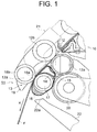
- FIG. 1 is a fragmentary side view showing a schematic configuration of a fiber bundle condensing device of a spinning machine according to the present embodiment.
- a fiber bundle condensing device 11 is disposed downstream of a drafting device 10.
- the drafting device 10 includes a delivery roller pair 12.
- the delivery roller pair 12 includes a lower front roller 12a and an upper front roller 12b.
- the upper front roller 12b is supported by a support member 19.
- the fiber bundle condensing device 11 includes a delivery portion 13, a suction pipe 14, an air-permeable apron 15, and an apron guide 16.
- the delivery portion 13 includes a lower nip roller 18a and an upper nip roller 18b.
- the lower nip roller 18a rotates integrally with a rotational shaft 17.
- a gear (not shown) is mounted to the rotational shaft 17.
- the gear is engaged with an intermediate gear 20.
- the intermediate gear 20 is engaged with a gear (not shown) that rotates integrally with the lower front roller 12a. With this configuration, the rotational force of the lower front roller 12a is transmitted to the lower nip roller 18a via the intermediate gear 20.
- the upper nip roller 18b is pressed against the lower nip roller 18a via the air-permeable apron 15.
- This pressing mechanism configures a nip portion 13a of the delivery portion 13.
- the air-permeable apron 15 and a fiber bundle F are placed on the nip portion 13a of the delivery portion 13.
- the upper nip roller 18b is supported by a pressing arm (not shown) via a support member 19 at every two spindle stations of the spinning machine.
- the suction pipe 14 is disposed downstream of the drafting device 10. More specifically, the suction pipe 14 is disposed downstream of the delivery roller pair 12 of the drafting device 10 and upstream of the nip portion 13a of the delivery portion 13 in a direction X in which the fiber bundle F is moved (hereinafter, the moving direction X).
- the suction pipe 14 is connected to a suction source (not shown) via a connection pipe 21.
- the air-permeable apron 15 is an endless belt having no ends, and formed of a woven fabric, such as the one having an appropriate air permeability.
- the air-permeable apron 15 is mounted in such a manner as to surround the suction pipe 14, the apron guide 16, and the lower nip roller 18a so that the air-permeable apron 15 passes through the nip portion 13a of the delivery portion 13.
- the air-permeable apron 15 transfers the fiber bundle F in the X direction while moving with the rotation of the lower nip roller 18a.
- a tip end 22a of the suction nozzle 22 is located below the apron guide 16.
- the suction nozzle 22 is adapted to suck the fiber bundle F discharged from the drafting device 10 when a fiber break has occurred.
- a distal end (not shown) of the suction nozzle 22 is connected to a single pneumatic duct (not shown) which is common to all of the spindle stations of the spinning machine.
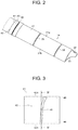
- FIG. 2 is a perspective view for illustrating the structure of the suction pipe 14 used in the fiber bundle condensing device 11 of FIG. 1 .
- the suction pipe 14 is a hollow and elongated pipe.
- the suction pipe 14 is disposed so as to extend in a direction crossing the moving direction X of the fiber bundle F.
- the suction pipe 14 extends longitudinally and perpendicularly to the plane of the sheet of FIG. 1 .
- the suction pipe 14 is made of aluminum and formed, for example, by extrusion molding.
- the suction pipe 14 includes three outer surfaces, namely, outer surfaces 31, 32, and 33.
- the outer surfaces will be referred to as the first outer surface 31, the second outer surface 32, and the third outer surface 33, respectively.
- the first outer surface 31 is positioned so as to extend along the moving path of the fiber bundle F and formed in a curved shape protruding outward.
- a plurality of suction holes 35 is formed in the first outer surface 31.
- the suction holes 35 are arranged at predetermined intervals in the longitudinal direction of the suction pipe 14. The intervals correspond to the positions of the spindle stations.
- Each suction hole 35 is formed in a slit shape extending in a direction crossing the longitudinal direction of the suction pipe 14.
- the second outer surface 32 is formed continuously from a first side 31a of the first outer surface 31, having a curved shape protruding inward.
- the third outer surface 33 is formed continuously from a second side 31b of the first outer surface 31, having a curved shape protruding inward.
- the second outer surface 32 and the third outer surface 33 are connected to each other at their sides located away from the first outer surface 31.
- a guide member 41 is attached to the suction pipe 14.
- the guide member 41 is a thin-walled member made of a metal.
- the guide member 41 is attached to the suction pipe 14 at a position corresponding to the mounting position of the air-permeable apron 15. It is to be noted that, in the present disclosure, a plurality of the guide members 41 are disposed at intervals along the longitudinal direction of the suction pipe 14. It is also to be noted, however, that only one of the guide members 41 is illustrated in FIG. 2 and description herein is made with reference to this representative guide member 14.
- the guide members 41 are attached to the suction pipe 14 corresponding to the respective suction holes 35.
- Each guide member 41 includes a guide surface 42 that is formed along the moving path of the fiber bundle F to guide the movement of the air-permeable apron 15.
- the air-permeable apron 15 moves with the rotation of the lower nip roller 18a while being in contact with the guide surface 42 of the guide member 41.
- the guide surface 42 is formed in a curved shape protruding outward, conforming to the first outer surface 31 of the suction pipe 14.
- a suction slit 43 is formed in the guide surface 42 of the guide member 41.
- the guide member 41 is attached to the suction pipe 14 so that the suction slit 43 is aligned with the suction hole 35 of the first outer surface 31 of the suction pipe 14. It is preferable that the suction hole 35 of the suction pipe 14 have the same shape and the same dimension as those of the suction slit 43. With the suction hole 35 thus formed before attaching the guide member 41 to the suction pipe 14, the guide member 41 may be attached to the suction pipe 14 easily and precisely by aligning the suction slit 43 with the suction hole 35. It is to be noted, however, that the shape and dimension of the suction hole 35 need not necessarily be the same as those of the suction slit 43.
- the suction hole 35 may be a hole which is greater than the suction slit 43 and has a different shape from that of the suction slit 43.
- FIG. 3 is a front view of the guide member 41
- FIG. 4 is a cross-sectional view of the guide member 41 taken along line IV-IV of FIG. 3 .
- the guide member 41 has a rectangular shape in a front view.
- the guide member 41 has two bent portions, namely, bent portions 45 and 46, formed at opposite ends thereof.
- the bent portion 45 is referred to as the first bent portion 45 and the bent portion 46 as the second bent portion 46.
- the first bent portion 45 is formed by bending a portion of the guide member 41 near one end of the suction slit 43 in the longitudinal direction thereof so as to bend from the first side 42a of the guide surface 42.
- the second bent portion 46 is formed by bending another portion of the guide member 41 near the other end of the suction slit 43 in the longitudinal direction thereof so as to bend from the second side 42b of the guide surface 42.
- the first bent portion 45 is bent conforming to the curved shape of the boundary between the first outer surface 31 and the second outer surface 32 of the suction pipe 14.
- the second bent portion 46 is bent conforming to the curved shape of the boundary between the first outer surface 31 and the third outer surface 33 of the suction pipe 14.
- FIG. 5 is a side view of the suction pipe 14 to which the guide member is attached
- FIG. 6 shows the suction pipe 14 as viewed in the direction of VI of FIG. 5 .
- the guide member 41 is attached to the suction pipe 14 such that the guide surface 42 of the guide member 41 overlaps with the first outer surface 31 of the suction pipe 14.
- the first bent portion 45 of the guide member 41 is disposed so as to overlap with the second outer surface 32 of the suction pipe 14.
- the second bent portion 46 is disposed so as to overlap with the third outer surface 33 of the suction pipe 14. In this way, the first bent portion 45 is hooked onto the second outer surface 32, and the second bent portion 46 is hooked onto the third outer surface 33.
- the guide member 41 is fixed to the suction pipe 14 with a fixation tape 51.
- the fixation tape 51 is an adhesive tape having an adhesive layer on one side of the substrate of the tape.
- Examples of the fixation tape 51 may include a resin tape including a resin substrate, a paper tape including a paper substrate, and a metallic tape including a metallic substrate.
- the fixation tape 51 should preferably be a resin tape.
- the fixation tape 51 should preferably be a metallic tape.
- the fixation tape 51 is attached to the second outer surface 32 and the third outer surface 33 of the suction pipe 14.
- the fixation tape 51 includes a first portion 51a and a second portion 51b.
- the first portion 51a overlaps with the first bent portion 45 of the guide member 41 on the second outer surface 32 of the suction pipe 14
- the second portion 51b overlaps with the second bent portion 46 of the guide member 41 on the third outer surface 33 of the suction pipe 14.
- the guide member 41 is fixed to the suction pipe 14 of the fiber bundle condensing device 11 with the fixation tape 51.
- the guide member 41 may be detached from the suction pipe 14 by removing the fixation tape 51 attached to the second outer surface 32 and the third outer surface 33 of the suction pipe 14, in order to replace the guide member 41.
- the guide surface 42 of the guide member 41 is disposed on the first outer surface 31 of the suction pipe 14 in an overlapping manner.
- the first bent portion 45 is hooked onto the second outer surface 32 of the suction pipe 14 and the second bent portion 46 is hooked onto the third outer surface 33 of the suction pipe 14.
- the position of the suction hole 35 of the suction pipe 14 and the position of the suction slit 43 of the guide member 41 are aligned.
- the fixation tape 51 is attached to the second outer surface 32 and the third outer surface 33 of the suction pipe 14.
- fixation tape 51 is attached such that the first portion 51a overlaps with the first bent portion 45 of the guide member 41 and the second portion 51b overlaps with the second bent portion 46 of the guide member 41. In this way the suction pipe 14 may be fixed to the guide member 41.
- the guide member 41 which has the guide surface 42 provided with the suction slit 43 is fixed to the suction pipe 14 with the fixation tape 51.
- the guide member 41 may be detached from the suction pipe 14 easily by removing the fixation tape 51 from the suction pipe 14, and the guide member 41 may be attached to the suction pipe 14 easily by attaching the fixation tape 51 to the suction pipe 14. Accordingly, the guide member 41 may be replaced easily. Furthermore, since no fasteners such as screws are used to fix the guide member 41, an increase in the number of parts and components resulting from the use of such fasteners and hence catching of cotton fly may be prevented. Furthermore, since there is no need of applying an adhesive agent to fix the guide member 41, the work of removing such an adhesive agent is eliminated.
- a single strip or sheet of the fixation tape 51 is used to fix a single guide member 41
- the fixation of the guide member 41 is not limited thereto.
- two guide members 41 that are adjacent to each other in the longitudinal direction of the suction pipe 14 may be fixed with a single strip or sheet of the fixation tape 51.
- three or more guide members 41 (not shown) that are adjacent in the longitudinal direction of the suction pipe 14 may be fixed with a single strip or sheet of the fixation tape 51.
- one strip or sheet of the fixation tape 51 may be used for the adjacent first bent portions 45, and another strip or sheet of the fixation tape 51 may be used for the adjacent second bent portions 46.
- a fiber bundle condensing device (11) of a spinning machine includes a suction pipe (14) that is disposed downstream of a drafting device (10), and an air-permeable apron (15) mounted on the suction pipe in such a manner as to surround the suction pipe (14).
- the fiber bundle condensing device (11) condenses a fiber bundle (F) drafted by the drafting device (10).
- the fiber bundle condensing device (11) includes a guide member (41) that is attached to the suction pipe (14) at a position corresponding to a mounting position of the air-permeable apron (15) and includes a guide surface (42) adapted to guide movement of the air-permeable apron (15), and a suction slit (43) formed in the guide surface (42); and a fixation tape (51) to fix the guide member (43) to the suction pipe (14).
Landscapes
- Engineering & Computer Science (AREA)
- Mechanical Engineering (AREA)
- Textile Engineering (AREA)
- Spinning Or Twisting Of Yarns (AREA)
Abstract
Description
- The present disclosure relates to a fiber bundle condensing device of a spinning machine.
- A spinning machine, such as a yarn twisting machine and a roving machine, generally includes a drafting device that stretches or drafts a fiber bundle which is a material of a yarn and a fiber bundle condensing device that condenses the fiber bundle drafted by the drafting device. The fiber bundle condensing device of a spinning machine also includes a suction pipe which has a guide surface and an air-permeable apron which is mounted on the guide surface of the suction pipe in a surrounding manner. A suction slit is formed in the guide surface of the suction pipe (see Japanese Patent Application Publication No.
2008-95233 - The wear of guide surface of the suction pipe progresses with the use. In such case, if the whole suction pipe needs to be replaced each time the wear amount of the guide surface has reached a specified level, the replacement cost will be increased. In view of the circumstances, in a conventional fiber bundle condensing device, it is proposed to form a guide surface on a thin-walled guide member, which is a separate member from the suction pipe, and to form a suction slit in the guide surface of the guide member (see Chinese Examined Utility Model Application Publication No.
202482530 , for example). In such fiber bundle condensing device, the thin-walled guide member is attached to the suction pipe. Therefore, when the guide surface is worn due to the friction with the air-permeable apron, only the guide member needs to be replaced, eliminating the replacement of the suction pipe. - When attaching a guide member to a suction pipe, as described above, the guide member needs to be fixed to the suction pipe in order to prevent the guide member from moving while the fiber bundle condensing device is operating. As the means for such purpose, the conventional fiber bundle condensing device uses a screw to fix the guide member to the suction pipe, or otherwise an adhesive agent is applied to the suction pipe to fix the guide member. However, such fixing means each have a problem as follows.
- First, fixing the guide member to the suction pipe with a screw involves an increase in the number of parts or components used, leading to an increase in the cost. Furthermore, fixing with a screw complicates the structure of the fiber bundle condensing device, and such complicated structure may catch cotton fly easily.
- Meanwhile, in the case of the guide member that is fixed to the suction pipe with an adhesive agent, when replacing the worn or used guide member with a new one, detachment of the used guide member from the suction pipe is troublesome and care must be taken so as not to damage the suction pipe during the removal work. Furthermore, the adhesive agent must also be removed in order to detach the used guide member. Thus, it takes much work and hours to replace the guide member.
- The present invention has been made in view of the circumstances above, and is directed to providing a fiber bundle condensing device of a spinning machine that permits a guide member having a suction slit to be fixed to a suction pipe and also permits replacement of the guide member with ease.
- In accordance with an aspect of the present disclosure, there is provided a fiber bundle condensing device of a spinning machine that includes a suction pipe that is disposed downstream of a drafting device, and an air-permeable apron mounted on the suction pipe in such a manner as to surround the suction pipe. The fiber bundle condensing device condenses a fiber bundle drafted by the drafting device. The fiber bundle condensing device includes a guide member that is attached to the suction pipe at a position corresponding to a mounting position of the air-permeable apron and includes a guide surface adapted to guide movement of the air-permeable apron, and a suction slit formed in the guide surface; and a fixation tape to fix the guide member to the suction pipe.
- Other aspects and advantages of the disclosure will become apparent from the following description, taken in conjunction with the accompanying drawings, illustrating by way of example the principles of the disclosure.
- The disclosure, together with objects and advantages thereof, may best be understood by reference to the following description of the embodiments together with the accompanying drawings in which:
-
FIG. 1 is a fragmentary side view showing a schematic configuration of a fiber bundle condensing device of a spinning machine according to an embodiment of the present invention; -
FIG. 2 is a perspective view for illustrating the structure of a suction pipe used in the fiber bundle condensing device ofFIG. 1 ; -
FIG. 3 is a front view of a guide member; -
FIG. 4 is a cross-sectional view taken along line IV-IV ofFIG. 3 ; -
FIG. 5 is a side view of the suction pipe to which the guide member is attached; -
FIG. 6 shows the suction pipe as viewed in the direction of VI ofFIG. 5 ; -
FIG. 7 is a view for illustrating a first variant of attachment form of a fixation tape; and -
FIG. 8 is a view for illustrating a second variant of attachment form of the fixation tape. - The following will describe an embodiment of the present invention with reference to the accompanying drawings.
-
FIG. 1 is a fragmentary side view showing a schematic configuration of a fiber bundle condensing device of a spinning machine according to the present embodiment. - As illustrated in
FIG. 1 , a fiberbundle condensing device 11 is disposed downstream of adrafting device 10. Thedrafting device 10 includes adelivery roller pair 12. Thedelivery roller pair 12 includes a lowerfront roller 12a and an upperfront roller 12b. Theupper front roller 12b is supported by asupport member 19. - The fiber
bundle condensing device 11 includes adelivery portion 13, asuction pipe 14, an air-permeable apron 15, and anapron guide 16. Thedelivery portion 13 includes alower nip roller 18a and anupper nip roller 18b. Thelower nip roller 18a rotates integrally with arotational shaft 17. A gear (not shown) is mounted to therotational shaft 17. The gear is engaged with anintermediate gear 20. Theintermediate gear 20 is engaged with a gear (not shown) that rotates integrally with thelower front roller 12a. With this configuration, the rotational force of thelower front roller 12a is transmitted to thelower nip roller 18a via theintermediate gear 20. - The
upper nip roller 18b is pressed against thelower nip roller 18a via the air-permeable apron 15. This pressing mechanism configures anip portion 13a of thedelivery portion 13. The air-permeable apron 15 and a fiber bundle F are placed on thenip portion 13a of thedelivery portion 13. As is the case of theupper front roller 12b of thedrafting device 10, theupper nip roller 18b is supported by a pressing arm (not shown) via asupport member 19 at every two spindle stations of the spinning machine. - The
suction pipe 14 is disposed downstream of thedrafting device 10. More specifically, thesuction pipe 14 is disposed downstream of thedelivery roller pair 12 of thedrafting device 10 and upstream of thenip portion 13a of thedelivery portion 13 in a direction X in which the fiber bundle F is moved (hereinafter, the moving direction X). Thesuction pipe 14 is connected to a suction source (not shown) via aconnection pipe 21. - The air-
permeable apron 15 is an endless belt having no ends, and formed of a woven fabric, such as the one having an appropriate air permeability. The air-permeable apron 15 is mounted in such a manner as to surround thesuction pipe 14, theapron guide 16, and thelower nip roller 18a so that the air-permeable apron 15 passes through thenip portion 13a of thedelivery portion 13. The air-permeable apron 15 transfers the fiber bundle F in the X direction while moving with the rotation of thelower nip roller 18a. Atip end 22a of thesuction nozzle 22 is located below theapron guide 16. Thesuction nozzle 22 is adapted to suck the fiber bundle F discharged from thedrafting device 10 when a fiber break has occurred. A distal end (not shown) of thesuction nozzle 22 is connected to a single pneumatic duct (not shown) which is common to all of the spindle stations of the spinning machine. -
FIG. 2 is a perspective view for illustrating the structure of thesuction pipe 14 used in the fiberbundle condensing device 11 ofFIG. 1 . - As illustrated in
FIG. 2 , thesuction pipe 14 is a hollow and elongated pipe. Thesuction pipe 14 is disposed so as to extend in a direction crossing the moving direction X of the fiber bundle F. In other words, thesuction pipe 14 extends longitudinally and perpendicularly to the plane of the sheet ofFIG. 1 . Thesuction pipe 14 is made of aluminum and formed, for example, by extrusion molding. Thesuction pipe 14 includes three outer surfaces, namely,outer surfaces outer surface 31, the secondouter surface 32, and the thirdouter surface 33, respectively. - The first
outer surface 31 is positioned so as to extend along the moving path of the fiber bundle F and formed in a curved shape protruding outward. A plurality of suction holes 35 is formed in the firstouter surface 31. The suction holes 35 are arranged at predetermined intervals in the longitudinal direction of thesuction pipe 14. The intervals correspond to the positions of the spindle stations. Eachsuction hole 35 is formed in a slit shape extending in a direction crossing the longitudinal direction of thesuction pipe 14. - The second
outer surface 32 is formed continuously from afirst side 31a of the firstouter surface 31, having a curved shape protruding inward. The thirdouter surface 33 is formed continuously from asecond side 31b of the firstouter surface 31, having a curved shape protruding inward. The secondouter surface 32 and the thirdouter surface 33 are connected to each other at their sides located away from the firstouter surface 31. - A
guide member 41 is attached to thesuction pipe 14. Theguide member 41 is a thin-walled member made of a metal. Theguide member 41 is attached to thesuction pipe 14 at a position corresponding to the mounting position of the air-permeable apron 15. It is to be noted that, in the present disclosure, a plurality of theguide members 41 are disposed at intervals along the longitudinal direction of thesuction pipe 14. It is also to be noted, however, that only one of theguide members 41 is illustrated inFIG. 2 and description herein is made with reference to thisrepresentative guide member 14. Theguide members 41 are attached to thesuction pipe 14 corresponding to the respective suction holes 35. Eachguide member 41 includes aguide surface 42 that is formed along the moving path of the fiber bundle F to guide the movement of the air-permeable apron 15. The air-permeable apron 15 moves with the rotation of the lower niproller 18a while being in contact with theguide surface 42 of theguide member 41. Theguide surface 42 is formed in a curved shape protruding outward, conforming to the firstouter surface 31 of thesuction pipe 14. - A suction slit 43 is formed in the
guide surface 42 of theguide member 41. Theguide member 41 is attached to thesuction pipe 14 so that the suction slit 43 is aligned with thesuction hole 35 of the firstouter surface 31 of thesuction pipe 14. It is preferable that thesuction hole 35 of thesuction pipe 14 have the same shape and the same dimension as those of the suction slit 43. With thesuction hole 35 thus formed before attaching theguide member 41 to thesuction pipe 14, theguide member 41 may be attached to thesuction pipe 14 easily and precisely by aligning the suction slit 43 with thesuction hole 35. It is to be noted, however, that the shape and dimension of thesuction hole 35 need not necessarily be the same as those of the suction slit 43. For example, thesuction hole 35 may be a hole which is greater than the suction slit 43 and has a different shape from that of the suction slit 43. -
FIG. 3 is a front view of theguide member 41, andFIG. 4 is a cross-sectional view of theguide member 41 taken along line IV-IV ofFIG. 3 . - As illustrated in
FIGS. 3 and4 , theguide member 41 has a rectangular shape in a front view. Theguide member 41 has two bent portions, namely,bent portions bent portion 45 is referred to as the firstbent portion 45 and thebent portion 46 as the secondbent portion 46. The firstbent portion 45 is formed by bending a portion of theguide member 41 near one end of the suction slit 43 in the longitudinal direction thereof so as to bend from thefirst side 42a of theguide surface 42. The secondbent portion 46 is formed by bending another portion of theguide member 41 near the other end of the suction slit 43 in the longitudinal direction thereof so as to bend from thesecond side 42b of theguide surface 42. The firstbent portion 45 is bent conforming to the curved shape of the boundary between the firstouter surface 31 and the secondouter surface 32 of thesuction pipe 14. The secondbent portion 46 is bent conforming to the curved shape of the boundary between the firstouter surface 31 and the thirdouter surface 33 of thesuction pipe 14. -
FIG. 5 is a side view of thesuction pipe 14 to which the guide member is attached, andFIG. 6 shows thesuction pipe 14 as viewed in the direction of VI ofFIG. 5 . - As illustrated in
FIGS. 5 and6 , theguide member 41 is attached to thesuction pipe 14 such that theguide surface 42 of theguide member 41 overlaps with the firstouter surface 31 of thesuction pipe 14. The firstbent portion 45 of theguide member 41 is disposed so as to overlap with the secondouter surface 32 of thesuction pipe 14. The secondbent portion 46 is disposed so as to overlap with the thirdouter surface 33 of thesuction pipe 14. In this way, the firstbent portion 45 is hooked onto the secondouter surface 32, and the secondbent portion 46 is hooked onto the thirdouter surface 33. - The
guide member 41 is fixed to thesuction pipe 14 with afixation tape 51. Thefixation tape 51 is an adhesive tape having an adhesive layer on one side of the substrate of the tape. Examples of thefixation tape 51 may include a resin tape including a resin substrate, a paper tape including a paper substrate, and a metallic tape including a metallic substrate. In terms of the easiness of attaching thefixation tape 51, thefixation tape 51 should preferably be a resin tape. In terms of the durability of thefixation tape 51, thefixation tape 51 should preferably be a metallic tape. - The
fixation tape 51 is attached to the secondouter surface 32 and the thirdouter surface 33 of thesuction pipe 14. Thefixation tape 51 includes afirst portion 51a and asecond portion 51b. When thefixation tape 51 is attached to thesuction pipe 14, thefirst portion 51a overlaps with the firstbent portion 45 of theguide member 41 on the secondouter surface 32 of thesuction pipe 14, and thesecond portion 51b overlaps with the secondbent portion 46 of theguide member 41 on the thirdouter surface 33 of thesuction pipe 14. - As described above, in the present embodiment, the
guide member 41 is fixed to thesuction pipe 14 of the fiberbundle condensing device 11 with thefixation tape 51. Thus, when theguide surface 42 of theguide member 41 is worn due to the friction with the air-permeable apron 15, theguide member 41 may be detached from thesuction pipe 14 by removing thefixation tape 51 attached to the secondouter surface 32 and the thirdouter surface 33 of thesuction pipe 14, in order to replace theguide member 41. - Meanwhile, when attaching the
guide member 41 to thesuction pipe 14, first, theguide surface 42 of theguide member 41 is disposed on the firstouter surface 31 of thesuction pipe 14 in an overlapping manner. At this time, the firstbent portion 45 is hooked onto the secondouter surface 32 of thesuction pipe 14 and the secondbent portion 46 is hooked onto the thirdouter surface 33 of thesuction pipe 14. Next, the position of thesuction hole 35 of thesuction pipe 14 and the position of the suction slit 43 of theguide member 41 are aligned. Then, thefixation tape 51 is attached to the secondouter surface 32 and the thirdouter surface 33 of thesuction pipe 14. More specifically, thefixation tape 51 is attached such that thefirst portion 51a overlaps with the firstbent portion 45 of theguide member 41 and thesecond portion 51b overlaps with the secondbent portion 46 of theguide member 41. In this way thesuction pipe 14 may be fixed to theguide member 41. - According to the fiber
bundle condensing device 11 of the present embodiment, theguide member 41 which has theguide surface 42 provided with the suction slit 43 is fixed to thesuction pipe 14 with thefixation tape 51. Thus, theguide member 41 may be detached from thesuction pipe 14 easily by removing thefixation tape 51 from thesuction pipe 14, and theguide member 41 may be attached to thesuction pipe 14 easily by attaching thefixation tape 51 to thesuction pipe 14. Accordingly, theguide member 41 may be replaced easily. Furthermore, since no fasteners such as screws are used to fix theguide member 41, an increase in the number of parts and components resulting from the use of such fasteners and hence catching of cotton fly may be prevented. Furthermore, since there is no need of applying an adhesive agent to fix theguide member 41, the work of removing such an adhesive agent is eliminated. - In the present embodiment, although a single strip or sheet of the
fixation tape 51 is used to fix asingle guide member 41, the fixation of theguide member 41 is not limited thereto. For example, as illustrated inFIG. 7 , twoguide members 41 that are adjacent to each other in the longitudinal direction of thesuction pipe 14 may be fixed with a single strip or sheet of thefixation tape 51. Or, alternatively, three or more guide members 41 (not shown) that are adjacent in the longitudinal direction of thesuction pipe 14 may be fixed with a single strip or sheet of thefixation tape 51. By fixing a plurality ofguide members 41 with a single strip or sheet of thefixation tape 51 as described above, man-hours for attaching thefixation tape 51 may be reduced. - Furthermore, as another example of the attachment of the
fixation tape 51, as illustrated inFIG. 8 , in order to fix a plurality of the guide members 41 (two guide members are illustrated in the example ofFIG. 8 ) that are adjacent to each other in the longitudinal direction of thesuction pipe 14, for example, one strip or sheet of thefixation tape 51 may be used for the adjacent firstbent portions 45, and another strip or sheet of thefixation tape 51 may be used for the adjacent secondbent portions 46. - A fiber bundle condensing device (11) of a spinning machine includes a suction pipe (14) that is disposed downstream of a drafting device (10), and an air-permeable apron (15) mounted on the suction pipe in such a manner as to surround the suction pipe (14). The fiber bundle condensing device (11) condenses a fiber bundle (F) drafted by the drafting device (10). The fiber bundle condensing device (11) includes a guide member (41) that is attached to the suction pipe (14) at a position corresponding to a mounting position of the air-permeable apron (15) and includes a guide surface (42) adapted to guide movement of the air-permeable apron (15), and a suction slit (43) formed in the guide surface (42); and a fixation tape (51) to fix the guide member (43) to the suction pipe (14).
Claims (5)
- A fiber bundle condensing device (11) of a spinning machine comprising:a suction pipe (14) that is disposed downstream of a drafting device (10); andan air-permeable apron (15) mounted on the suction pipe (14) in such a manner as to surround the suction pipe (14), the fiber bundle condensing device (11) condensing a fiber bundle (F) drafted by the drafting device (10), characterized in thatthe fiber bundle condensing device (11) includes:a guide member (41) that is attached to the suction pipe (14) at a position corresponding to a mounting position of the air-permeable apron (15) and includes a guide surface (42) adapted to guide movement of the air-permeable apron (15), and a suction slit (43) formed in the guide surface (42); anda fixation tape (51) to fix the guide member (41) to the suction pipe (14).
- The fiber bundle condensing device (11) of the spinning machine according to claim 1, characterized in that
the suction pipe (14) includes:a first outer surface (31) that is positioned so as to extend along a moving path of the fiber bundle (F);a second outer surface (32) formed continuously from a first side (31a) of the first outer surface (31); anda third outer surface (33) formed continuously from a second side (31 b) of the first outer surface (31),the guide member (41) includes:a first bent portion (45) which is bent from the guide surface (42) near one end of the suction slit (43) in the longitudinal direction of the suction slit (43); anda second bent portion (46) which is bent from the guide surface (42) near the other end of the suction slit (43) in the longitudinal direction thereof,the first bent portion (45) is disposed on the second outer surface (32), and the second bent portion (46) is disposed on the third outer surface (33),
the fixation tape (51) is attached to the second outer surface (32) and the third outer surface (33) of the suction pipe (14) such that a portion of the fixation tape (51) overlaps with the first bent portion (51a) and another portion of the fixation tape (51) overlaps with the second bent portion (46). - The fiber bundle condensing device (11) of the spinning machine according to claim 1 or 2, characterized in that
the fiber bundle condensing device (11) includes a plurality of the guide members (41), and the guide members (41) are disposed at intervals along the longitudinal direction of the suction pipe (14), and
at least two of the guide members (41) that are adjacent to each other in the longitudinal direction of the suction pipe (14) are fixed with a single sheet of the fixation tape (51). - The fiber bundle condensing device (11) of the spinning machine according to any one of claims 1 to 3, characterized in that the fixation tape (51) is a resin tape.
- The fiber bundle condensing device (11) of the spinning machine according to any one of claims 1 to 3, characterized in that the fixation tape (51) is a metallic tape.
Applications Claiming Priority (1)
| Application Number | Priority Date | Filing Date | Title |
|---|---|---|---|
| JP2018227228A JP7180333B2 (en) | 2018-12-04 | 2018-12-04 | Spinning machine fiber bundle concentrator |
Publications (2)
| Publication Number | Publication Date |
|---|---|
| EP3663446A1 true EP3663446A1 (en) | 2020-06-10 |
| EP3663446B1 EP3663446B1 (en) | 2024-06-12 |
Family
ID=68531396
Family Applications (1)
| Application Number | Title | Priority Date | Filing Date |
|---|---|---|---|
| EP19208231.1A Active EP3663446B1 (en) | 2018-12-04 | 2019-11-11 | Fiber bundle condensing device of spinning machine |
Country Status (3)
| Country | Link |
|---|---|
| EP (1) | EP3663446B1 (en) |
| JP (1) | JP7180333B2 (en) |
| CN (1) | CN111270360B (en) |
Cited By (1)
| Publication number | Priority date | Publication date | Assignee | Title |
|---|---|---|---|---|
| EP4047115A1 (en) * | 2021-02-17 | 2022-08-24 | Kabushiki Kaisha Toyota Jidoshokki | Fiber bundle condensing device of spinning machine |
Families Citing this family (1)
| Publication number | Priority date | Publication date | Assignee | Title |
|---|---|---|---|---|
| BE1019331A5 (en) | 2010-05-10 | 2012-06-05 | Flooring Ind Ltd Sarl | FLOOR PANEL AND METHODS FOR MANUFACTURING FLOOR PANELS. |
Citations (7)
| Publication number | Priority date | Publication date | Assignee | Title |
|---|---|---|---|---|
| DE19903113A1 (en) * | 1999-01-27 | 2000-08-03 | Stahlecker Fritz | Assembly to condense drawn sliver has a sharp chamfered edge at least at one end of the suction slit to prevent clogging at the perforated carrier belt and build-up between the laying and sliding surfaces |
| DE10036786A1 (en) * | 2000-07-28 | 2002-02-07 | Stahlecker Fritz | Condensing stage for drawn sliver, for spinning, has a steel spring clip around the base body as reinforcement to reduce wear and seal the suction slit against false air |
| CN1477248A (en) * | 2003-07-07 | 2004-02-25 | 宁波德昌精密纺织机械有限公司 | Aspiration tube on compact spinning unit |
| JP2008095233A (en) | 2006-10-11 | 2008-04-24 | Toyota Industries Corp | Fiber bundle-gathering device in spinning machine |
| CN202214487U (en) * | 2011-08-04 | 2012-05-09 | 江阴市华方新技术科研有限公司 | Replaceable abrasion-resistant compact yarn special-shaped aspiration channel |
| CN202482530U (en) | 2011-12-30 | 2012-10-10 | 日照裕鑫动力有限公司 | Combined type compact spinning compacting device |
| CN202786574U (en) * | 2012-06-08 | 2013-03-13 | 常州市同和纺织机械制造有限公司 | Mechanism of compact spinning special pipe with replaceable compact working face |
Family Cites Families (13)
| Publication number | Priority date | Publication date | Assignee | Title |
|---|---|---|---|---|
| GB542997A (en) * | 1940-07-01 | 1900-01-01 | ||
| JP3542069B2 (en) * | 1999-01-06 | 2004-07-14 | 東邦テナックス株式会社 | Draft device |
| DE10158001A1 (en) * | 2001-11-22 | 2003-06-05 | Stahlecker Gmbh Wilhelm | Device on a spinning machine for compacting a fiber structure |
| DE10218876A1 (en) * | 2002-04-26 | 2003-11-13 | Rieter Ag Maschf | Tensioning arrangement for apron on spinning machine drafting system includes a spring-loaded internal rotating guide |
| JP4419703B2 (en) * | 2004-06-22 | 2010-02-24 | 株式会社豊田自動織機 | Fiber bundle concentrator in spinning machine |
| DE102005045451B4 (en) * | 2005-09-22 | 2008-05-08 | Oerlikon Textile Gmbh & Co. Kg | Device for compacting a fiber structure |
| JP2008111217A (en) | 2006-10-30 | 2008-05-15 | Kanai Hiroaki | Fluff-laying down tool and ring fine spinning machine |
| DE102007024234B4 (en) * | 2007-05-21 | 2022-06-23 | Wilhelm Stahlecker Gmbh | Drafting system for warping a fiber structure |
| JP5282724B2 (en) | 2009-12-09 | 2013-09-04 | 株式会社豊田自動織機 | Suction pipe in fiber bundle concentrator for spinning machine and method for manufacturing the same |
| DE102010032341A1 (en) * | 2010-07-27 | 2012-02-02 | Wilhelm Stahlecker Gmbh | Drafting system for a staple fiber bandage and pressure roller unit therefor |
| JP2015036456A (en) * | 2013-08-12 | 2015-02-23 | 株式会社豊田自動織機 | Cleaning device for fiber bundle delivering device of first roving frame |
| CN204474827U (en) * | 2014-12-12 | 2015-07-15 | 桐乡市张驰纺业有限公司 | Spinning structure |
| DE102015109644A1 (en) * | 2015-06-17 | 2016-12-22 | Rieter Ingolstadt Gmbh | Sliver guide |
-
2018
- 2018-12-04 JP JP2018227228A patent/JP7180333B2/en active Active
-
2019
- 2019-11-11 EP EP19208231.1A patent/EP3663446B1/en active Active
- 2019-11-29 CN CN201911199966.1A patent/CN111270360B/en active Active
Patent Citations (7)
| Publication number | Priority date | Publication date | Assignee | Title |
|---|---|---|---|---|
| DE19903113A1 (en) * | 1999-01-27 | 2000-08-03 | Stahlecker Fritz | Assembly to condense drawn sliver has a sharp chamfered edge at least at one end of the suction slit to prevent clogging at the perforated carrier belt and build-up between the laying and sliding surfaces |
| DE10036786A1 (en) * | 2000-07-28 | 2002-02-07 | Stahlecker Fritz | Condensing stage for drawn sliver, for spinning, has a steel spring clip around the base body as reinforcement to reduce wear and seal the suction slit against false air |
| CN1477248A (en) * | 2003-07-07 | 2004-02-25 | 宁波德昌精密纺织机械有限公司 | Aspiration tube on compact spinning unit |
| JP2008095233A (en) | 2006-10-11 | 2008-04-24 | Toyota Industries Corp | Fiber bundle-gathering device in spinning machine |
| CN202214487U (en) * | 2011-08-04 | 2012-05-09 | 江阴市华方新技术科研有限公司 | Replaceable abrasion-resistant compact yarn special-shaped aspiration channel |
| CN202482530U (en) | 2011-12-30 | 2012-10-10 | 日照裕鑫动力有限公司 | Combined type compact spinning compacting device |
| CN202786574U (en) * | 2012-06-08 | 2013-03-13 | 常州市同和纺织机械制造有限公司 | Mechanism of compact spinning special pipe with replaceable compact working face |
Cited By (1)
| Publication number | Priority date | Publication date | Assignee | Title |
|---|---|---|---|---|
| EP4047115A1 (en) * | 2021-02-17 | 2022-08-24 | Kabushiki Kaisha Toyota Jidoshokki | Fiber bundle condensing device of spinning machine |
Also Published As
| Publication number | Publication date |
|---|---|
| CN111270360B (en) | 2022-05-17 |
| JP2020090734A (en) | 2020-06-11 |
| EP3663446B1 (en) | 2024-06-12 |
| JP7180333B2 (en) | 2022-11-30 |
| CN111270360A (en) | 2020-06-12 |
Similar Documents
| Publication | Publication Date | Title |
|---|---|---|
| EP3663446B1 (en) | Fiber bundle condensing device of spinning machine | |
| CN103221593B (en) | There is the spinning machine of compressor | |
| JP3820951B2 (en) | Fiber bundle focusing device in spinning machine | |
| CN103221594A (en) | Drives for compression devices on spinning machines | |
| CN104520480A (en) | Support elements for compact installations | |
| JP2008095233A (en) | Fiber bundle-gathering device in spinning machine | |
| EP4047115B1 (en) | Fiber bundle condensing device of spinning machine | |
| EP3754063B1 (en) | Fine spinning machine | |
| JP4179227B2 (en) | Fiber bundle concentrator in spinning machine | |
| JP3786069B2 (en) | Spinning fiber bundle bundling device | |
| CN105378163B (en) | Accumulating device for accumulating fiber sliver in spinning machine | |
| JP5515754B2 (en) | Spinning fiber bundle bundling device | |
| CN106544764B (en) | Cleaning device for compaction equipment | |
| CN102345191B (en) | Drafting system for staple fibre complex and the spinning machine for this drafting system | |
| CN111465728A (en) | Drafting device with gathering mechanism for spinning machines | |
| CN202380161U (en) | Monitoring device of spinning machine | |
| KR20070004771A (en) | Spring Doctor | |
| CN100355965C (en) | Collecting tube for fiber strip collector of spinning machine | |
| US8099835B2 (en) | Wearing coating for delivery rollers of a drawing roller frame | |
| JP7758462B2 (en) | Fiber bundle concentrating device for spinning machine | |
| ITMI980223A1 (en) | BREAKING DEVICE FOR FIBER TAPES FOR OPEN END ROTOR YARNS | |
| EP4737620A1 (en) | System for compacting fibers | |
| CN111826756A (en) | Fiber bundle bundling device of spinning machine | |
| CN216550890U (en) | Independent cleaning device for drafting shaft of flax drawing frame | |
| CN106245171B (en) | Seal wire wheel assembly and godet wheel device |
Legal Events
| Date | Code | Title | Description |
|---|---|---|---|
| PUAI | Public reference made under article 153(3) epc to a published international application that has entered the european phase |
Free format text: ORIGINAL CODE: 0009012 |
|
| STAA | Information on the status of an ep patent application or granted ep patent |
Free format text: STATUS: REQUEST FOR EXAMINATION WAS MADE |
|
| 17P | Request for examination filed |
Effective date: 20191111 |
|
| AK | Designated contracting states |
Kind code of ref document: A1 Designated state(s): AL AT BE BG CH CY CZ DE DK EE ES FI FR GB GR HR HU IE IS IT LI LT LU LV MC MK MT NL NO PL PT RO RS SE SI SK SM TR |
|
| AX | Request for extension of the european patent |
Extension state: BA ME |
|
| STAA | Information on the status of an ep patent application or granted ep patent |
Free format text: STATUS: EXAMINATION IS IN PROGRESS |
|
| 17Q | First examination report despatched |
Effective date: 20220519 |
|
| P01 | Opt-out of the competence of the unified patent court (upc) registered |
Effective date: 20230519 |
|
| GRAP | Despatch of communication of intention to grant a patent |
Free format text: ORIGINAL CODE: EPIDOSNIGR1 |
|
| STAA | Information on the status of an ep patent application or granted ep patent |
Free format text: STATUS: GRANT OF PATENT IS INTENDED |
|
| INTG | Intention to grant announced |
Effective date: 20240201 |
|
| GRAS | Grant fee paid |
Free format text: ORIGINAL CODE: EPIDOSNIGR3 |
|
| GRAA | (expected) grant |
Free format text: ORIGINAL CODE: 0009210 |
|
| STAA | Information on the status of an ep patent application or granted ep patent |
Free format text: STATUS: THE PATENT HAS BEEN GRANTED |
|
| AK | Designated contracting states |
Kind code of ref document: B1 Designated state(s): AL AT BE BG CH CY CZ DE DK EE ES FI FR GB GR HR HU IE IS IT LI LT LU LV MC MK MT NL NO PL PT RO RS SE SI SK SM TR |
|
| REG | Reference to a national code |
Ref country code: GB Ref legal event code: FG4D |
|
| REG | Reference to a national code |
Ref country code: CH Ref legal event code: EP |
|
| REG | Reference to a national code |
Ref country code: DE Ref legal event code: R096 Ref document number: 602019053493 Country of ref document: DE |
|
| REG | Reference to a national code |
Ref country code: IE Ref legal event code: FG4D |
|
| PG25 | Lapsed in a contracting state [announced via postgrant information from national office to epo] |
Ref country code: BG Free format text: LAPSE BECAUSE OF FAILURE TO SUBMIT A TRANSLATION OF THE DESCRIPTION OR TO PAY THE FEE WITHIN THE PRESCRIBED TIME-LIMIT Effective date: 20240612 |
|
| PG25 | Lapsed in a contracting state [announced via postgrant information from national office to epo] |
Ref country code: FI Free format text: LAPSE BECAUSE OF FAILURE TO SUBMIT A TRANSLATION OF THE DESCRIPTION OR TO PAY THE FEE WITHIN THE PRESCRIBED TIME-LIMIT Effective date: 20240612 Ref country code: HR Free format text: LAPSE BECAUSE OF FAILURE TO SUBMIT A TRANSLATION OF THE DESCRIPTION OR TO PAY THE FEE WITHIN THE PRESCRIBED TIME-LIMIT Effective date: 20240612 |
|
| REG | Reference to a national code |
Ref country code: LT Ref legal event code: MG9D |
|
| PG25 | Lapsed in a contracting state [announced via postgrant information from national office to epo] |
Ref country code: GR Free format text: LAPSE BECAUSE OF FAILURE TO SUBMIT A TRANSLATION OF THE DESCRIPTION OR TO PAY THE FEE WITHIN THE PRESCRIBED TIME-LIMIT Effective date: 20240913 |
|
| REG | Reference to a national code |
Ref country code: NL Ref legal event code: MP Effective date: 20240612 |
|
| PG25 | Lapsed in a contracting state [announced via postgrant information from national office to epo] |
Ref country code: ES Free format text: LAPSE BECAUSE OF FAILURE TO SUBMIT A TRANSLATION OF THE DESCRIPTION OR TO PAY THE FEE WITHIN THE PRESCRIBED TIME-LIMIT Effective date: 20240612 |
|
| PG25 | Lapsed in a contracting state [announced via postgrant information from national office to epo] |
Ref country code: LV Free format text: LAPSE BECAUSE OF FAILURE TO SUBMIT A TRANSLATION OF THE DESCRIPTION OR TO PAY THE FEE WITHIN THE PRESCRIBED TIME-LIMIT Effective date: 20240612 |
|
| PG25 | Lapsed in a contracting state [announced via postgrant information from national office to epo] |
Ref country code: NO Free format text: LAPSE BECAUSE OF FAILURE TO SUBMIT A TRANSLATION OF THE DESCRIPTION OR TO PAY THE FEE WITHIN THE PRESCRIBED TIME-LIMIT Effective date: 20240912 Ref country code: LV Free format text: LAPSE BECAUSE OF FAILURE TO SUBMIT A TRANSLATION OF THE DESCRIPTION OR TO PAY THE FEE WITHIN THE PRESCRIBED TIME-LIMIT Effective date: 20240612 Ref country code: HR Free format text: LAPSE BECAUSE OF FAILURE TO SUBMIT A TRANSLATION OF THE DESCRIPTION OR TO PAY THE FEE WITHIN THE PRESCRIBED TIME-LIMIT Effective date: 20240612 Ref country code: GR Free format text: LAPSE BECAUSE OF FAILURE TO SUBMIT A TRANSLATION OF THE DESCRIPTION OR TO PAY THE FEE WITHIN THE PRESCRIBED TIME-LIMIT Effective date: 20240913 Ref country code: FI Free format text: LAPSE BECAUSE OF FAILURE TO SUBMIT A TRANSLATION OF THE DESCRIPTION OR TO PAY THE FEE WITHIN THE PRESCRIBED TIME-LIMIT Effective date: 20240612 Ref country code: ES Free format text: LAPSE BECAUSE OF FAILURE TO SUBMIT A TRANSLATION OF THE DESCRIPTION OR TO PAY THE FEE WITHIN THE PRESCRIBED TIME-LIMIT Effective date: 20240612 Ref country code: BG Free format text: LAPSE BECAUSE OF FAILURE TO SUBMIT A TRANSLATION OF THE DESCRIPTION OR TO PAY THE FEE WITHIN THE PRESCRIBED TIME-LIMIT Effective date: 20240612 Ref country code: RS Free format text: LAPSE BECAUSE OF FAILURE TO SUBMIT A TRANSLATION OF THE DESCRIPTION OR TO PAY THE FEE WITHIN THE PRESCRIBED TIME-LIMIT Effective date: 20240912 |
|
| PG25 | Lapsed in a contracting state [announced via postgrant information from national office to epo] |
Ref country code: NL Free format text: LAPSE BECAUSE OF FAILURE TO SUBMIT A TRANSLATION OF THE DESCRIPTION OR TO PAY THE FEE WITHIN THE PRESCRIBED TIME-LIMIT Effective date: 20240612 |
|
| REG | Reference to a national code |
Ref country code: AT Ref legal event code: MK05 Ref document number: 1694312 Country of ref document: AT Kind code of ref document: T Effective date: 20240612 |
|
| PG25 | Lapsed in a contracting state [announced via postgrant information from national office to epo] |
Ref country code: NL Free format text: LAPSE BECAUSE OF FAILURE TO SUBMIT A TRANSLATION OF THE DESCRIPTION OR TO PAY THE FEE WITHIN THE PRESCRIBED TIME-LIMIT Effective date: 20240612 |
|
| PG25 | Lapsed in a contracting state [announced via postgrant information from national office to epo] |
Ref country code: PT Free format text: LAPSE BECAUSE OF FAILURE TO SUBMIT A TRANSLATION OF THE DESCRIPTION OR TO PAY THE FEE WITHIN THE PRESCRIBED TIME-LIMIT Effective date: 20241014 |
|
| PG25 | Lapsed in a contracting state [announced via postgrant information from national office to epo] |
Ref country code: PT Free format text: LAPSE BECAUSE OF FAILURE TO SUBMIT A TRANSLATION OF THE DESCRIPTION OR TO PAY THE FEE WITHIN THE PRESCRIBED TIME-LIMIT Effective date: 20241014 |
|
| PG25 | Lapsed in a contracting state [announced via postgrant information from national office to epo] |
Ref country code: PL Free format text: LAPSE BECAUSE OF FAILURE TO SUBMIT A TRANSLATION OF THE DESCRIPTION OR TO PAY THE FEE WITHIN THE PRESCRIBED TIME-LIMIT Effective date: 20240612 |
|
| PG25 | Lapsed in a contracting state [announced via postgrant information from national office to epo] |
Ref country code: EE Free format text: LAPSE BECAUSE OF FAILURE TO SUBMIT A TRANSLATION OF THE DESCRIPTION OR TO PAY THE FEE WITHIN THE PRESCRIBED TIME-LIMIT Effective date: 20240612 |
|
| PG25 | Lapsed in a contracting state [announced via postgrant information from national office to epo] |
Ref country code: IS Free format text: LAPSE BECAUSE OF FAILURE TO SUBMIT A TRANSLATION OF THE DESCRIPTION OR TO PAY THE FEE WITHIN THE PRESCRIBED TIME-LIMIT Effective date: 20241012 Ref country code: AT Free format text: LAPSE BECAUSE OF FAILURE TO SUBMIT A TRANSLATION OF THE DESCRIPTION OR TO PAY THE FEE WITHIN THE PRESCRIBED TIME-LIMIT Effective date: 20240612 |
|
| PG25 | Lapsed in a contracting state [announced via postgrant information from national office to epo] |
Ref country code: CZ Free format text: LAPSE BECAUSE OF FAILURE TO SUBMIT A TRANSLATION OF THE DESCRIPTION OR TO PAY THE FEE WITHIN THE PRESCRIBED TIME-LIMIT Effective date: 20240612 |
|
| PG25 | Lapsed in a contracting state [announced via postgrant information from national office to epo] |
Ref country code: SK Free format text: LAPSE BECAUSE OF FAILURE TO SUBMIT A TRANSLATION OF THE DESCRIPTION OR TO PAY THE FEE WITHIN THE PRESCRIBED TIME-LIMIT Effective date: 20240612 Ref country code: RO Free format text: LAPSE BECAUSE OF FAILURE TO SUBMIT A TRANSLATION OF THE DESCRIPTION OR TO PAY THE FEE WITHIN THE PRESCRIBED TIME-LIMIT Effective date: 20240612 |
|
| PG25 | Lapsed in a contracting state [announced via postgrant information from national office to epo] |
Ref country code: SM Free format text: LAPSE BECAUSE OF FAILURE TO SUBMIT A TRANSLATION OF THE DESCRIPTION OR TO PAY THE FEE WITHIN THE PRESCRIBED TIME-LIMIT Effective date: 20240612 |
|
| PG25 | Lapsed in a contracting state [announced via postgrant information from national office to epo] |
Ref country code: SM Free format text: LAPSE BECAUSE OF FAILURE TO SUBMIT A TRANSLATION OF THE DESCRIPTION OR TO PAY THE FEE WITHIN THE PRESCRIBED TIME-LIMIT Effective date: 20240612 Ref country code: SK Free format text: LAPSE BECAUSE OF FAILURE TO SUBMIT A TRANSLATION OF THE DESCRIPTION OR TO PAY THE FEE WITHIN THE PRESCRIBED TIME-LIMIT Effective date: 20240612 Ref country code: RO Free format text: LAPSE BECAUSE OF FAILURE TO SUBMIT A TRANSLATION OF THE DESCRIPTION OR TO PAY THE FEE WITHIN THE PRESCRIBED TIME-LIMIT Effective date: 20240612 Ref country code: PL Free format text: LAPSE BECAUSE OF FAILURE TO SUBMIT A TRANSLATION OF THE DESCRIPTION OR TO PAY THE FEE WITHIN THE PRESCRIBED TIME-LIMIT Effective date: 20240612 Ref country code: IS Free format text: LAPSE BECAUSE OF FAILURE TO SUBMIT A TRANSLATION OF THE DESCRIPTION OR TO PAY THE FEE WITHIN THE PRESCRIBED TIME-LIMIT Effective date: 20241012 Ref country code: EE Free format text: LAPSE BECAUSE OF FAILURE TO SUBMIT A TRANSLATION OF THE DESCRIPTION OR TO PAY THE FEE WITHIN THE PRESCRIBED TIME-LIMIT Effective date: 20240612 Ref country code: CZ Free format text: LAPSE BECAUSE OF FAILURE TO SUBMIT A TRANSLATION OF THE DESCRIPTION OR TO PAY THE FEE WITHIN THE PRESCRIBED TIME-LIMIT Effective date: 20240612 Ref country code: AT Free format text: LAPSE BECAUSE OF FAILURE TO SUBMIT A TRANSLATION OF THE DESCRIPTION OR TO PAY THE FEE WITHIN THE PRESCRIBED TIME-LIMIT Effective date: 20240612 |
|
| REG | Reference to a national code |
Ref country code: DE Ref legal event code: R097 Ref document number: 602019053493 Country of ref document: DE |
|
| PG25 | Lapsed in a contracting state [announced via postgrant information from national office to epo] |
Ref country code: DK Free format text: LAPSE BECAUSE OF FAILURE TO SUBMIT A TRANSLATION OF THE DESCRIPTION OR TO PAY THE FEE WITHIN THE PRESCRIBED TIME-LIMIT Effective date: 20240612 |
|
| PLBE | No opposition filed within time limit |
Free format text: ORIGINAL CODE: 0009261 |
|
| STAA | Information on the status of an ep patent application or granted ep patent |
Free format text: STATUS: NO OPPOSITION FILED WITHIN TIME LIMIT |
|
| 26N | No opposition filed |
Effective date: 20250313 |
|
| PG25 | Lapsed in a contracting state [announced via postgrant information from national office to epo] |
Ref country code: MC Free format text: LAPSE BECAUSE OF FAILURE TO SUBMIT A TRANSLATION OF THE DESCRIPTION OR TO PAY THE FEE WITHIN THE PRESCRIBED TIME-LIMIT Effective date: 20240612 |
|
| PG25 | Lapsed in a contracting state [announced via postgrant information from national office to epo] |
Ref country code: LU Free format text: LAPSE BECAUSE OF NON-PAYMENT OF DUE FEES Effective date: 20241111 |
|
| GBPC | Gb: european patent ceased through non-payment of renewal fee |
Effective date: 20241111 |
|
| REG | Reference to a national code |
Ref country code: BE Ref legal event code: MM Effective date: 20241130 |
|
| PG25 | Lapsed in a contracting state [announced via postgrant information from national office to epo] |
Ref country code: SE Free format text: LAPSE BECAUSE OF FAILURE TO SUBMIT A TRANSLATION OF THE DESCRIPTION OR TO PAY THE FEE WITHIN THE PRESCRIBED TIME-LIMIT Effective date: 20240612 |
|
| PG25 | Lapsed in a contracting state [announced via postgrant information from national office to epo] |
Ref country code: GB Free format text: LAPSE BECAUSE OF NON-PAYMENT OF DUE FEES Effective date: 20241111 Ref country code: BE Free format text: LAPSE BECAUSE OF NON-PAYMENT OF DUE FEES Effective date: 20241130 |
|
| PG25 | Lapsed in a contracting state [announced via postgrant information from national office to epo] |
Ref country code: FR Free format text: LAPSE BECAUSE OF NON-PAYMENT OF DUE FEES Effective date: 20241130 |
|
| PG25 | Lapsed in a contracting state [announced via postgrant information from national office to epo] |
Ref country code: IE Free format text: LAPSE BECAUSE OF NON-PAYMENT OF DUE FEES Effective date: 20241111 |
|
| REG | Reference to a national code |
Ref country code: CH Ref legal event code: U11 Free format text: ST27 STATUS EVENT CODE: U-0-0-U10-U11 (AS PROVIDED BY THE NATIONAL OFFICE) Effective date: 20251201 |
|
| PGFP | Annual fee paid to national office [announced via postgrant information from national office to epo] |
Ref country code: DE Payment date: 20250930 Year of fee payment: 7 |
|
| PGFP | Annual fee paid to national office [announced via postgrant information from national office to epo] |
Ref country code: IT Payment date: 20251022 Year of fee payment: 7 |
|
| PGFP | Annual fee paid to national office [announced via postgrant information from national office to epo] |
Ref country code: CH Payment date: 20251201 Year of fee payment: 7 |
|
| PG25 | Lapsed in a contracting state [announced via postgrant information from national office to epo] |
Ref country code: HU Free format text: LAPSE BECAUSE OF FAILURE TO SUBMIT A TRANSLATION OF THE DESCRIPTION OR TO PAY THE FEE WITHIN THE PRESCRIBED TIME-LIMIT; INVALID AB INITIO Effective date: 20191111 |
|
| PG25 | Lapsed in a contracting state [announced via postgrant information from national office to epo] |
Ref country code: CY Free format text: LAPSE BECAUSE OF FAILURE TO SUBMIT A TRANSLATION OF THE DESCRIPTION OR TO PAY THE FEE WITHIN THE PRESCRIBED TIME-LIMIT; INVALID AB INITIO Effective date: 20191111 |