EP3663426B1 - Hot-dip galvanized steel sheet - Google Patents
Hot-dip galvanized steel sheet Download PDFInfo
- Publication number
- EP3663426B1 EP3663426B1 EP17920296.5A EP17920296A EP3663426B1 EP 3663426 B1 EP3663426 B1 EP 3663426B1 EP 17920296 A EP17920296 A EP 17920296A EP 3663426 B1 EP3663426 B1 EP 3663426B1
- Authority
- EP
- European Patent Office
- Prior art keywords
- steel sheet
- hot
- layer
- less
- thickness
- Prior art date
- Legal status (The legal status is an assumption and is not a legal conclusion. Google has not performed a legal analysis and makes no representation as to the accuracy of the status listed.)
- Revoked
Links
Images
Classifications
-
- B—PERFORMING OPERATIONS; TRANSPORTING
- B32—LAYERED PRODUCTS
- B32B—LAYERED PRODUCTS, i.e. PRODUCTS BUILT-UP OF STRATA OF FLAT OR NON-FLAT, e.g. CELLULAR OR HONEYCOMB, FORM
- B32B15/00—Layered products comprising a layer of metal
- B32B15/01—Layered products comprising a layer of metal all layers being exclusively metallic
- B32B15/013—Layered products comprising a layer of metal all layers being exclusively metallic one layer being formed of an iron alloy or steel, another layer being formed of a metal other than iron or aluminium
-
- C—CHEMISTRY; METALLURGY
- C22—METALLURGY; FERROUS OR NON-FERROUS ALLOYS; TREATMENT OF ALLOYS OR NON-FERROUS METALS
- C22C—ALLOYS
- C22C38/00—Ferrous alloys, e.g. steel alloys
- C22C38/18—Ferrous alloys, e.g. steel alloys containing chromium
- C22C38/40—Ferrous alloys, e.g. steel alloys containing chromium with nickel
- C22C38/58—Ferrous alloys, e.g. steel alloys containing chromium with nickel with more than 1.5% by weight of manganese
-
- C—CHEMISTRY; METALLURGY
- C21—METALLURGY OF IRON
- C21D—MODIFYING THE PHYSICAL STRUCTURE OF FERROUS METALS; GENERAL DEVICES FOR HEAT TREATMENT OF FERROUS OR NON-FERROUS METALS OR ALLOYS; MAKING METAL MALLEABLE, e.g. BY DECARBURISATION OR TEMPERING
- C21D6/00—Heat treatment of ferrous alloys
- C21D6/001—Heat treatment of ferrous alloys containing Ni
-
- C—CHEMISTRY; METALLURGY
- C21—METALLURGY OF IRON
- C21D—MODIFYING THE PHYSICAL STRUCTURE OF FERROUS METALS; GENERAL DEVICES FOR HEAT TREATMENT OF FERROUS OR NON-FERROUS METALS OR ALLOYS; MAKING METAL MALLEABLE, e.g. BY DECARBURISATION OR TEMPERING
- C21D6/00—Heat treatment of ferrous alloys
- C21D6/002—Heat treatment of ferrous alloys containing Cr
-
- C—CHEMISTRY; METALLURGY
- C21—METALLURGY OF IRON
- C21D—MODIFYING THE PHYSICAL STRUCTURE OF FERROUS METALS; GENERAL DEVICES FOR HEAT TREATMENT OF FERROUS OR NON-FERROUS METALS OR ALLOYS; MAKING METAL MALLEABLE, e.g. BY DECARBURISATION OR TEMPERING
- C21D6/00—Heat treatment of ferrous alloys
- C21D6/005—Heat treatment of ferrous alloys containing Mn
-
- C—CHEMISTRY; METALLURGY
- C21—METALLURGY OF IRON
- C21D—MODIFYING THE PHYSICAL STRUCTURE OF FERROUS METALS; GENERAL DEVICES FOR HEAT TREATMENT OF FERROUS OR NON-FERROUS METALS OR ALLOYS; MAKING METAL MALLEABLE, e.g. BY DECARBURISATION OR TEMPERING
- C21D6/00—Heat treatment of ferrous alloys
- C21D6/008—Heat treatment of ferrous alloys containing Si
-
- C—CHEMISTRY; METALLURGY
- C21—METALLURGY OF IRON
- C21D—MODIFYING THE PHYSICAL STRUCTURE OF FERROUS METALS; GENERAL DEVICES FOR HEAT TREATMENT OF FERROUS OR NON-FERROUS METALS OR ALLOYS; MAKING METAL MALLEABLE, e.g. BY DECARBURISATION OR TEMPERING
- C21D8/00—Modifying the physical properties of ferrous metals or ferrous alloys by deformation combined with, or followed by, heat treatment
- C21D8/02—Modifying the physical properties of ferrous metals or ferrous alloys by deformation combined with, or followed by, heat treatment during manufacturing of plates or strips
-
- C—CHEMISTRY; METALLURGY
- C21—METALLURGY OF IRON
- C21D—MODIFYING THE PHYSICAL STRUCTURE OF FERROUS METALS; GENERAL DEVICES FOR HEAT TREATMENT OF FERROUS OR NON-FERROUS METALS OR ALLOYS; MAKING METAL MALLEABLE, e.g. BY DECARBURISATION OR TEMPERING
- C21D8/00—Modifying the physical properties of ferrous metals or ferrous alloys by deformation combined with, or followed by, heat treatment
- C21D8/02—Modifying the physical properties of ferrous metals or ferrous alloys by deformation combined with, or followed by, heat treatment during manufacturing of plates or strips
- C21D8/0221—Modifying the physical properties of ferrous metals or ferrous alloys by deformation combined with, or followed by, heat treatment during manufacturing of plates or strips characterised by the working steps
- C21D8/0236—Cold rolling
-
- C—CHEMISTRY; METALLURGY
- C21—METALLURGY OF IRON
- C21D—MODIFYING THE PHYSICAL STRUCTURE OF FERROUS METALS; GENERAL DEVICES FOR HEAT TREATMENT OF FERROUS OR NON-FERROUS METALS OR ALLOYS; MAKING METAL MALLEABLE, e.g. BY DECARBURISATION OR TEMPERING
- C21D9/00—Heat treatment, e.g. annealing, hardening, quenching or tempering, adapted for particular articles; Furnaces therefor
- C21D9/46—Heat treatment, e.g. annealing, hardening, quenching or tempering, adapted for particular articles; Furnaces therefor for sheet metals
-
- C—CHEMISTRY; METALLURGY
- C22—METALLURGY; FERROUS OR NON-FERROUS ALLOYS; TREATMENT OF ALLOYS OR NON-FERROUS METALS
- C22C—ALLOYS
- C22C38/00—Ferrous alloys, e.g. steel alloys
- C22C38/002—Ferrous alloys, e.g. steel alloys containing In, Mg, or other elements not provided for in one single group C22C38/001 - C22C38/60
-
- C—CHEMISTRY; METALLURGY
- C22—METALLURGY; FERROUS OR NON-FERROUS ALLOYS; TREATMENT OF ALLOYS OR NON-FERROUS METALS
- C22C—ALLOYS
- C22C38/00—Ferrous alloys, e.g. steel alloys
- C22C38/005—Ferrous alloys, e.g. steel alloys containing rare earths, i.e. Sc, Y, Lanthanides
-
- C—CHEMISTRY; METALLURGY
- C22—METALLURGY; FERROUS OR NON-FERROUS ALLOYS; TREATMENT OF ALLOYS OR NON-FERROUS METALS
- C22C—ALLOYS
- C22C38/00—Ferrous alloys, e.g. steel alloys
- C22C38/02—Ferrous alloys, e.g. steel alloys containing silicon
-
- C—CHEMISTRY; METALLURGY
- C22—METALLURGY; FERROUS OR NON-FERROUS ALLOYS; TREATMENT OF ALLOYS OR NON-FERROUS METALS
- C22C—ALLOYS
- C22C38/00—Ferrous alloys, e.g. steel alloys
- C22C38/06—Ferrous alloys, e.g. steel alloys containing aluminium
-
- C—CHEMISTRY; METALLURGY
- C22—METALLURGY; FERROUS OR NON-FERROUS ALLOYS; TREATMENT OF ALLOYS OR NON-FERROUS METALS
- C22C—ALLOYS
- C22C38/00—Ferrous alloys, e.g. steel alloys
- C22C38/08—Ferrous alloys, e.g. steel alloys containing nickel
-
- C—CHEMISTRY; METALLURGY
- C22—METALLURGY; FERROUS OR NON-FERROUS ALLOYS; TREATMENT OF ALLOYS OR NON-FERROUS METALS
- C22C—ALLOYS
- C22C38/00—Ferrous alloys, e.g. steel alloys
- C22C38/16—Ferrous alloys, e.g. steel alloys containing copper
-
- C—CHEMISTRY; METALLURGY
- C22—METALLURGY; FERROUS OR NON-FERROUS ALLOYS; TREATMENT OF ALLOYS OR NON-FERROUS METALS
- C22C—ALLOYS
- C22C38/00—Ferrous alloys, e.g. steel alloys
- C22C38/18—Ferrous alloys, e.g. steel alloys containing chromium
- C22C38/22—Ferrous alloys, e.g. steel alloys containing chromium with molybdenum or tungsten
-
- C—CHEMISTRY; METALLURGY
- C22—METALLURGY; FERROUS OR NON-FERROUS ALLOYS; TREATMENT OF ALLOYS OR NON-FERROUS METALS
- C22C—ALLOYS
- C22C38/00—Ferrous alloys, e.g. steel alloys
- C22C38/18—Ferrous alloys, e.g. steel alloys containing chromium
- C22C38/26—Ferrous alloys, e.g. steel alloys containing chromium with niobium or tantalum
-
- C—CHEMISTRY; METALLURGY
- C22—METALLURGY; FERROUS OR NON-FERROUS ALLOYS; TREATMENT OF ALLOYS OR NON-FERROUS METALS
- C22C—ALLOYS
- C22C38/00—Ferrous alloys, e.g. steel alloys
- C22C38/18—Ferrous alloys, e.g. steel alloys containing chromium
- C22C38/28—Ferrous alloys, e.g. steel alloys containing chromium with titanium or zirconium
-
- C—CHEMISTRY; METALLURGY
- C22—METALLURGY; FERROUS OR NON-FERROUS ALLOYS; TREATMENT OF ALLOYS OR NON-FERROUS METALS
- C22C—ALLOYS
- C22C38/00—Ferrous alloys, e.g. steel alloys
- C22C38/18—Ferrous alloys, e.g. steel alloys containing chromium
- C22C38/32—Ferrous alloys, e.g. steel alloys containing chromium with boron
-
- C—CHEMISTRY; METALLURGY
- C22—METALLURGY; FERROUS OR NON-FERROUS ALLOYS; TREATMENT OF ALLOYS OR NON-FERROUS METALS
- C22C—ALLOYS
- C22C38/00—Ferrous alloys, e.g. steel alloys
- C22C38/18—Ferrous alloys, e.g. steel alloys containing chromium
- C22C38/38—Ferrous alloys, e.g. steel alloys containing chromium with more than 1.5% by weight of manganese
-
- C—CHEMISTRY; METALLURGY
- C22—METALLURGY; FERROUS OR NON-FERROUS ALLOYS; TREATMENT OF ALLOYS OR NON-FERROUS METALS
- C22C—ALLOYS
- C22C38/00—Ferrous alloys, e.g. steel alloys
- C22C38/18—Ferrous alloys, e.g. steel alloys containing chromium
- C22C38/40—Ferrous alloys, e.g. steel alloys containing chromium with nickel
- C22C38/42—Ferrous alloys, e.g. steel alloys containing chromium with nickel with copper
-
- C—CHEMISTRY; METALLURGY
- C22—METALLURGY; FERROUS OR NON-FERROUS ALLOYS; TREATMENT OF ALLOYS OR NON-FERROUS METALS
- C22C—ALLOYS
- C22C38/00—Ferrous alloys, e.g. steel alloys
- C22C38/18—Ferrous alloys, e.g. steel alloys containing chromium
- C22C38/40—Ferrous alloys, e.g. steel alloys containing chromium with nickel
- C22C38/44—Ferrous alloys, e.g. steel alloys containing chromium with nickel with molybdenum or tungsten
-
- C—CHEMISTRY; METALLURGY
- C23—COATING METALLIC MATERIAL; COATING MATERIAL WITH METALLIC MATERIAL; CHEMICAL SURFACE TREATMENT; DIFFUSION TREATMENT OF METALLIC MATERIAL; COATING BY VACUUM EVAPORATION, BY SPUTTERING, BY ION IMPLANTATION OR BY CHEMICAL VAPOUR DEPOSITION, IN GENERAL; INHIBITING CORROSION OF METALLIC MATERIAL OR INCRUSTATION IN GENERAL
- C23C—COATING METALLIC MATERIAL; COATING MATERIAL WITH METALLIC MATERIAL; SURFACE TREATMENT OF METALLIC MATERIAL BY DIFFUSION INTO THE SURFACE, BY CHEMICAL CONVERSION OR SUBSTITUTION; COATING BY VACUUM EVAPORATION, BY SPUTTERING, BY ION IMPLANTATION OR BY CHEMICAL VAPOUR DEPOSITION, IN GENERAL
- C23C2/00—Hot-dipping or immersion processes for applying the coating material in the molten state without affecting the shape; Apparatus therefor
- C23C2/02—Pretreatment of the material to be coated, e.g. for coating on selected surface areas
-
- C—CHEMISTRY; METALLURGY
- C23—COATING METALLIC MATERIAL; COATING MATERIAL WITH METALLIC MATERIAL; CHEMICAL SURFACE TREATMENT; DIFFUSION TREATMENT OF METALLIC MATERIAL; COATING BY VACUUM EVAPORATION, BY SPUTTERING, BY ION IMPLANTATION OR BY CHEMICAL VAPOUR DEPOSITION, IN GENERAL; INHIBITING CORROSION OF METALLIC MATERIAL OR INCRUSTATION IN GENERAL
- C23C—COATING METALLIC MATERIAL; COATING MATERIAL WITH METALLIC MATERIAL; SURFACE TREATMENT OF METALLIC MATERIAL BY DIFFUSION INTO THE SURFACE, BY CHEMICAL CONVERSION OR SUBSTITUTION; COATING BY VACUUM EVAPORATION, BY SPUTTERING, BY ION IMPLANTATION OR BY CHEMICAL VAPOUR DEPOSITION, IN GENERAL
- C23C2/00—Hot-dipping or immersion processes for applying the coating material in the molten state without affecting the shape; Apparatus therefor
- C23C2/02—Pretreatment of the material to be coated, e.g. for coating on selected surface areas
- C23C2/022—Pretreatment of the material to be coated, e.g. for coating on selected surface areas by heating
- C23C2/0224—Two or more thermal pretreatments
-
- C—CHEMISTRY; METALLURGY
- C23—COATING METALLIC MATERIAL; COATING MATERIAL WITH METALLIC MATERIAL; CHEMICAL SURFACE TREATMENT; DIFFUSION TREATMENT OF METALLIC MATERIAL; COATING BY VACUUM EVAPORATION, BY SPUTTERING, BY ION IMPLANTATION OR BY CHEMICAL VAPOUR DEPOSITION, IN GENERAL; INHIBITING CORROSION OF METALLIC MATERIAL OR INCRUSTATION IN GENERAL
- C23C—COATING METALLIC MATERIAL; COATING MATERIAL WITH METALLIC MATERIAL; SURFACE TREATMENT OF METALLIC MATERIAL BY DIFFUSION INTO THE SURFACE, BY CHEMICAL CONVERSION OR SUBSTITUTION; COATING BY VACUUM EVAPORATION, BY SPUTTERING, BY ION IMPLANTATION OR BY CHEMICAL VAPOUR DEPOSITION, IN GENERAL
- C23C2/00—Hot-dipping or immersion processes for applying the coating material in the molten state without affecting the shape; Apparatus therefor
- C23C2/02—Pretreatment of the material to be coated, e.g. for coating on selected surface areas
- C23C2/024—Pretreatment of the material to be coated, e.g. for coating on selected surface areas by cleaning or etching
-
- C—CHEMISTRY; METALLURGY
- C23—COATING METALLIC MATERIAL; COATING MATERIAL WITH METALLIC MATERIAL; CHEMICAL SURFACE TREATMENT; DIFFUSION TREATMENT OF METALLIC MATERIAL; COATING BY VACUUM EVAPORATION, BY SPUTTERING, BY ION IMPLANTATION OR BY CHEMICAL VAPOUR DEPOSITION, IN GENERAL; INHIBITING CORROSION OF METALLIC MATERIAL OR INCRUSTATION IN GENERAL
- C23C—COATING METALLIC MATERIAL; COATING MATERIAL WITH METALLIC MATERIAL; SURFACE TREATMENT OF METALLIC MATERIAL BY DIFFUSION INTO THE SURFACE, BY CHEMICAL CONVERSION OR SUBSTITUTION; COATING BY VACUUM EVAPORATION, BY SPUTTERING, BY ION IMPLANTATION OR BY CHEMICAL VAPOUR DEPOSITION, IN GENERAL
- C23C2/00—Hot-dipping or immersion processes for applying the coating material in the molten state without affecting the shape; Apparatus therefor
- C23C2/04—Hot-dipping or immersion processes for applying the coating material in the molten state without affecting the shape; Apparatus therefor characterised by the coating material
- C23C2/06—Zinc or cadmium or alloys based thereon
-
- C—CHEMISTRY; METALLURGY
- C23—COATING METALLIC MATERIAL; COATING MATERIAL WITH METALLIC MATERIAL; CHEMICAL SURFACE TREATMENT; DIFFUSION TREATMENT OF METALLIC MATERIAL; COATING BY VACUUM EVAPORATION, BY SPUTTERING, BY ION IMPLANTATION OR BY CHEMICAL VAPOUR DEPOSITION, IN GENERAL; INHIBITING CORROSION OF METALLIC MATERIAL OR INCRUSTATION IN GENERAL
- C23C—COATING METALLIC MATERIAL; COATING MATERIAL WITH METALLIC MATERIAL; SURFACE TREATMENT OF METALLIC MATERIAL BY DIFFUSION INTO THE SURFACE, BY CHEMICAL CONVERSION OR SUBSTITUTION; COATING BY VACUUM EVAPORATION, BY SPUTTERING, BY ION IMPLANTATION OR BY CHEMICAL VAPOUR DEPOSITION, IN GENERAL
- C23C2/00—Hot-dipping or immersion processes for applying the coating material in the molten state without affecting the shape; Apparatus therefor
- C23C2/26—After-treatment
- C23C2/28—Thermal after-treatment, e.g. treatment in oil bath
- C23C2/29—Cooling or quenching
-
- C—CHEMISTRY; METALLURGY
- C23—COATING METALLIC MATERIAL; COATING MATERIAL WITH METALLIC MATERIAL; CHEMICAL SURFACE TREATMENT; DIFFUSION TREATMENT OF METALLIC MATERIAL; COATING BY VACUUM EVAPORATION, BY SPUTTERING, BY ION IMPLANTATION OR BY CHEMICAL VAPOUR DEPOSITION, IN GENERAL; INHIBITING CORROSION OF METALLIC MATERIAL OR INCRUSTATION IN GENERAL
- C23C—COATING METALLIC MATERIAL; COATING MATERIAL WITH METALLIC MATERIAL; SURFACE TREATMENT OF METALLIC MATERIAL BY DIFFUSION INTO THE SURFACE, BY CHEMICAL CONVERSION OR SUBSTITUTION; COATING BY VACUUM EVAPORATION, BY SPUTTERING, BY ION IMPLANTATION OR BY CHEMICAL VAPOUR DEPOSITION, IN GENERAL
- C23C2/00—Hot-dipping or immersion processes for applying the coating material in the molten state without affecting the shape; Apparatus therefor
- C23C2/34—Hot-dipping or immersion processes for applying the coating material in the molten state without affecting the shape; Apparatus therefor characterised by the shape of the material to be treated
- C23C2/36—Elongated material
- C23C2/40—Plates; Strips
-
- C—CHEMISTRY; METALLURGY
- C21—METALLURGY OF IRON
- C21D—MODIFYING THE PHYSICAL STRUCTURE OF FERROUS METALS; GENERAL DEVICES FOR HEAT TREATMENT OF FERROUS OR NON-FERROUS METALS OR ALLOYS; MAKING METAL MALLEABLE, e.g. BY DECARBURISATION OR TEMPERING
- C21D2211/00—Microstructure comprising significant phases
- C21D2211/001—Austenite
-
- C—CHEMISTRY; METALLURGY
- C21—METALLURGY OF IRON
- C21D—MODIFYING THE PHYSICAL STRUCTURE OF FERROUS METALS; GENERAL DEVICES FOR HEAT TREATMENT OF FERROUS OR NON-FERROUS METALS OR ALLOYS; MAKING METAL MALLEABLE, e.g. BY DECARBURISATION OR TEMPERING
- C21D2211/00—Microstructure comprising significant phases
- C21D2211/002—Bainite
-
- C—CHEMISTRY; METALLURGY
- C21—METALLURGY OF IRON
- C21D—MODIFYING THE PHYSICAL STRUCTURE OF FERROUS METALS; GENERAL DEVICES FOR HEAT TREATMENT OF FERROUS OR NON-FERROUS METALS OR ALLOYS; MAKING METAL MALLEABLE, e.g. BY DECARBURISATION OR TEMPERING
- C21D2211/00—Microstructure comprising significant phases
- C21D2211/005—Ferrite
-
- C—CHEMISTRY; METALLURGY
- C21—METALLURGY OF IRON
- C21D—MODIFYING THE PHYSICAL STRUCTURE OF FERROUS METALS; GENERAL DEVICES FOR HEAT TREATMENT OF FERROUS OR NON-FERROUS METALS OR ALLOYS; MAKING METAL MALLEABLE, e.g. BY DECARBURISATION OR TEMPERING
- C21D2211/00—Microstructure comprising significant phases
- C21D2211/008—Martensite
Definitions
- the present invention relates to a high-strength hot-dip galvanized steel sheet excellent in ductility, bendability, hole expandability, and plating adhesion at the time of bending deformation and excellent in continuous bending fatigue resistance.
- Patent Literatures 1 to 3 there were proposed methods of forming oxides inside a steel sheet and reducing the oxides at an interface between a base iron and a plating layer that cause plating peeling.
- carbon in the surface layer of the steel sheet bonds to oxygen to be gasified.
- the carbon is released from the steel sheet, and thus, the strength of the region of the steel sheet from which the carbon has been released decreases significantly in some cases.
- the strength of the surface layer of the steel sheet decreases, fatigue resistance that strongly depends on the properties of the surface layer portion deteriorates, giving rise to a concern about a great decrease in fatigue strength.
- Patent Literature 4 in order to enhance the adhesion of the plating layer, in Patent Literature 4, there was proposed a method of enhancing plating adhesion by additionally applying a new annealing step and an acid pickling step before an ordinary annealing step to thereby reform the surface of a base steel sheet.
- the number of steps is increased as compared to a normal method of manufacturing a high-strength metal coated steel sheet, thus causing a problem in costs.
- Patent Literature 5 there was proposed a method of enhancing plating adhesion by removing carbon from a surface layer portion of a base steel sheet.
- the strength of the region from which carbon has been removed decreases significantly. Therefore, the method described in Patent Literature 5 makes fatigue resistance, which strongly depends on the properties of the surface layer portion, deteriorate, giving rise to a concern about a great decrease in fatigue strength.
- Patent Literatures 6 and 7 there were proposed steel sheets with improved plating adhesion that have a plating layer whose contents of Mn, Al, and Si were controlled to suitable ranges.
- Patent Literature 8 there was proposed a high-strength steel sheet in which a microstructure of the steel sheet was made of only ferrite as a method for enhancing plating adhesion.
- the microstructure is made of only soft ferrite in the steel sheet described in Patent Literature 8, it is impossible to obtain a sufficiently high strength.
- Patent Literature 12 discloses a hot-dip galvanized steel sheet having a refined layer.
- an object of the present invention is to provide a high-strength hot-dip galvanized steel sheet excellent in formabilities of a steel sheet, which are represented by, particularly, bendability and stretch flange formability (to be also referred to as stretch flangeability simply below) and excellent in plating appearance uniformity, fatigue resistance, weldability, corrosion resistance, and plating adhesion.
- the present inventors have repeatedly conducted intensive investigations for obtaining a high-strength hot-dip galvanized steel sheet excellent in formabilities of a steel sheet represented by bendability and stretch flange formability and fatigue resistance, weldability, corrosion resistance, and plating adhesion.
- the present inventors have improved stretch flangeability (hole expandability) by appropriately controlling structural fractions of a microstructure of a steel sheet.
- the present inventors have improved bendability and fatigue resistance by controlling a volume fraction of a hard phase at the side of a base steel sheet from an interface between a plating layer and the base steel sheet.
- the present inventors have found out that even when using a steel sheet containing large amounts of Si and Mn as a plating substrate, a specific fine-grain layer made of ultrafine particles of a ferrite phase is formed immediately under a Fe-Al alloy layer formed at an interface between a plating layer formed by using a plating bath with Al added thereto and a base steel sheet, thereby making it possible to suppress occurrence and propagation of cracks at the time of working and suppress plating peeling starting from the cracks.
- the thicknesses of the fine-grain layer and the Fe-Al alloy layer in the width direction of the steel sheet are controlled to fall within specific ranges, thereby making it possible to obtain a hot-dip galvanized steel sheet excellent not only in plating adhesion but also in appearance uniformity.
- thermoforming a hot-dip galvanized steel sheet excellent in plating appearance uniformity, formability, fatigue resistance, weldability, corrosion resistance, and plating adhesion.
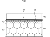
- Fig. 1 is a view illustrating one example of a schematic view of a cross-sectional structure of a hot-dip galvanized steel sheet of the present invention.
- a hot-dip galvanized steel sheet according to the present invention is formed by forming a hot-dip galvanizing layer (to be also referred to as a plating layer simply below) on a surface of a base steel sheet (to be also referred to as a steel sheet simply below) having chemical components containing, in mass%, C: 0.040% to 0.280%, Si: 0.05% to 2.00%, Mn: 0.50% to 3.50%, P: 0.0001% to 0.100%, S: 0.0001% to 0.0100%, Al: 0.001% to 1.500%, O: 0.0001% to 0.0100%, N: 0.0001% to 0.0100%, and a balance composed of Fe and impurities.
- the sheet thickness of the base steel sheet is 0.6 mm or more and less than 5.0 mm.
- the sheet thickness of the base steel sheet is less than 0.6 mm, it is difficult to keep the shape of the base steel sheet flat, which is not appropriate.
- the sheet thickness of the base steel sheet is 5.0 mm or more, the control of cooling in a manufacturing process becomes difficult, to fail to obtain a predetermined microstructure, resulting in that formability sometimes deteriorates.
- the plating layer has a Fe content of more than 0% and 3.0% or less and an Al content of more than 0% and 1.0% or less.
- the C content is contained to increase the strength of the base steel sheet.
- the C content exceeds 0.280%, spot weldability deteriorates, and thus the C content is set to 0.280% or less.
- the C content is preferably 0.250% or less and more preferably 0.220% or less.
- the C content is set to 0.040% or more.
- the C content is preferably 0.055% or more and more preferably 0.070% or more.
- the Si content is set to 0.05% or more.
- the Si content is preferably 0.10% or more and more preferably 0.25% or more.
- Mn is contained to increase strength by increasing hardenability of the base steel sheet.
- the Mn content exceeds 3.50%, a coarse Mn-concentrated portion is generated in the thickness middle portion of the base steel sheet and embrittlement easily occurs, and thus, a trouble such as cracking of a cast slab easily occurs. Therefore, the Mn content is set to 3.50% or less.
- an increase in the Mn content results in deterioration in the spot weldability of the hot-dip galvanized steel sheet. For this reason, the Mn content is preferably 3.00% or less and more preferably 2.80% or less.
- the Mn content when the Mn content is less than 0.50%, a large amount of soft structure is formed during cooling after annealing, to thus be difficult to secure a sufficiently high maximum tensile strength. Accordingly, the Mn content needs to be 0.50% or more.
- the Mn content is preferably 0.80% or more and more preferably 1.00% or more.
- P is an element that makes a steel material brittle, and when the P content exceeds 0.1000%, troubles such as cracking of a cast slab and cracking of a slab during hot rolling easily occur, and therefore, the P content is set to 0.1000% or less.
- P is also an element that makes a molten portion generated by spot welding brittle, and the P content is preferably set to 0.0400% or less and further preferably set to 0.0200% or less in order to obtain a sufficient welded joint strength.
- setting the P content to less than 0.0001% results in a great increase in manufacturing cost, and thus, the P content is preferably set to 0.010% or more with its lower limit value set to 0.0001%.
- S is an element that bonds to Mn to form coarse MnS and impair formabilities such as ductility, hole expandability (stretch flangeability), and bendability, and thus the S content is set to 0.0100% or less.
- S is also an element that impairs spot weldability. Therefore, the S content is preferably set to 0.0060% or less and more preferably set to 0.0035% or less.
- setting the S content to less than 0.0001% results in a great increase in manufacturing cost. Therefore, the S content is preferably set to 0.0005% or more and further preferably set to 0.0010% or more with its lower limit value set to 0.0001%.
- Al is an element that makes a steel material brittle.
- the Al content exceeds 1.500%, a trouble such as cracking of a cast slab easily occurs, and thus the Al content is set to 1.500% or less.
- the Al content is more preferably set to 1.200% or less and further preferably set to 1.000% or less.
- the Al content is set to 0.001% or more.
- Al is an element effective also as a deoxidizing material, but in order to obtain a deoxidation effect more sufficiently, the Al content is more preferably set to 0.010% or more.
- N is an element that forms coarse nitrides to impair formabilities such as ductility, hole expandability (stretch flangeability), and bendability, and thus, it is necessary to suppress its content.
- the N content exceeds 0.0100%, the deterioration in formabilities becomes significant, and thus the upper limit of the N content is set to 0.0100%. Further, containing N excessively causes occurrence of blowholes at the time of welding, and thus a lower content thereof is better. From these viewpoints, the N content is preferably 0.0070% or less and more preferably 0.0050% or less.
- the lower limit of the N content is set to 0.0001% or more.
- the N content is preferably 0.0003% or more and more preferably 0.0005% or more.
- O forms oxides to impair the formabilities such as ductility, hole expandability (stretch flangeability), and bendability of the hot-dip galvanized steel sheet, and thus, it is necessary to suppress the O content.
- the O content exceeds 0.0100%, the deterioration in the formabilities becomes significant, and thus the upper limit of the O content is set to 0.0100%.
- the O content is preferably 0.0050% or less and more preferably 0.0030% or less. Even when the lower limit of the O content is not particularly determined, the effects of the invention are exhibited, but setting the O content to less than 0.0001% results in a great increase in manufacturing cost, and thus its lower limit is set to 0.0001%.
- the O content is preferably 0.0003% or more and more preferably 0.0005% or more.
- the following elements may be contained in the base steel sheet of the hot-dip galvanized steel sheet according to this embodiment as necessary.
- the base steel sheet according to the invention optionally contains one or two or more selected from a group consisting of Ti: 0.001% to 0.150%, Nb: 0.001% to 0.100%, and V: 0.001% to 0.300%.
- Ti is an element that contributes to an increase in the strength of the hot-dip galvanized steel sheet by precipitate strengthening, strengthening by grain refinement through the suppression of the growth of ferrite crystal grains, and dislocation strengthening through the suppression of recrystallization.
- the Ti content exceeds 0.150%, the amount of precipitated carbonitrides increases and formability deteriorates, and thus, the Ti content is set to 0.150% or less.
- the Ti content is preferably 0.080% or less.
- the Ti content is preferably 0.001% or more.
- the Ti content is more preferably 0.010% or more.
- Nb is an element that contributes to an increase in the strength of the hot-dip galvanized steel sheet by precipitate strengthening, strengthening by grain refinement through the suppression of the growth of ferrite crystal grains, and dislocation strengthening through the suppression of recrystallization.
- the Nb content exceeds 0.100%, the amount of precipitated carbonitrides increases and the formability of the hot-dip galvanized steel sheet deteriorates, and thus the Nb content is set to 0.100% or less. From the viewpoint of formability, the Nb content is preferably 0.060% or less.
- the Nb content is preferably 0.001% or more.
- the Nb content is more preferably 0.005% or more.
- V is an element that contributes to an increase in the strength of the hot-dip galvanized steel sheet by precipitate strengthening, strengthening by grain refinement through the suppression of the growth of ferrite crystal grains, and dislocation strengthening through the suppression of recrystallization.
- the V content is set to 0.300% or less.
- the V content is preferably 0.200% or less.
- the V content is preferably 0.001% or more and further preferably 0.010% or more.
- the base steel sheet according to the invention optionally contains one or two or more selected from a group consisting of Cr: 0.01% to 2.00%, Ni: 0.01% to 2.00%, Cu: 0.01% to 2.00%, Mo: 0.01% to 2.00%, B: 0.0001% to 0.0100%, and W: 0.01% to 2.00%.
- Cr is an element that suppresses phase transformation at a high temperature and is effective for high-strengthening of the hot-dip galvanized steel sheet and may be contained instead of part of C and/or Mn.
- the Cr content is preferably set to 2.00% or less and is further preferably 1.20% or less.
- the Cr content is preferably 0.01% or more and further preferably 0.10% or more.
- Ni is an element that suppresses phase transformation at a high temperature and is effective for high-strengthening of the hot-dip galvanized steel sheet and may be contained instead of part of C and/or Mn.
- the Ni content exceeds 2.00%, weldability is impaired, and thus, the Ni content is preferably set to 2.00% or less and further preferably 1.20% or less.
- the Ni content is preferably 0.01% or more and further preferably 0.10% or more.
- Cu is an element that increases the strength of the hot-dip galvanized steel sheet by being present in steel as fine particles and can be contained instead of part of C and/or Mn.
- the Cu content exceeds 2.00%, weldability is impaired, and thus, the Cu content is set to 2.00% or less.
- the Cu content is preferably 1.20% or less.
- the Cu content is preferably 0.01% or more and further preferably 0.10% or more.
- B is an element that suppresses phase transformation at a high temperature and is effective for high-strengthening of the hot-dip galvanized steel sheet and may be contained instead of part of C and/or Mn.
- the B content is set to 0.0100% or less.
- the B content is preferably 0.0050% or less.
- the B content is preferably set to 0.0001% or more.
- the B content is more preferably 0.0005% or more.
- W is an element that suppresses phase transformation at a high temperature and is effective for high-strengthening of the hot-dip galvanized steel sheet and may be contained instead of part of C and/or Mn.
- the W content is preferably 1.20% or less.
- the W content is preferably 0.01% or more and further preferably 0.10% or more.
- Ca, Ce, Mg, Zr, La, and REM are elements effective for improving the formability of the hot-dip galvanized steel sheet, and one or two or more of these elements can be contained.
- the total content of one or two or more selected from a group consisting of Ca, Ce, Mg, Zr, La, and REM exceeds 0.0100%, ductility may be impaired, and thus, the total content of the respective elements is set to 0.0100% or less.
- the total content of these respective elements is preferably 0.0070% or less.
- the total content of these respective elements is preferably 0.0001% or more.
- the total content of one or two or more selected from a group consisting of Ca, Ce, Mg, Zr, La, and REM is further preferably 0.0010% or more.
- a balance other than the above-described respective elements is Fe and impurities.
- Ca, Ce, Mg, Zr, La, and REM a minute amount of them, which is less than the above-described lower limit value of the total content of them, is allowed to be contained as an impurity.
- a microstructure of the base steel sheet of the hot-dip galvanized steel sheet according to the present invention.
- the properties of the steel material change according to the microstructure, but when the microstructure is quantified, it is unrealistic to quantify and define the microstructure over the entire region of the steel material. Therefore, in the present invention, a microstructure in a range of 1/8 thickness to 3/8 thickness of which center is a 1/4 thickness from the surface of the base steel sheet, which indicates a typical microstructure of the steel material, is quantified and defined.
- the microstructure in a sheet thickness middle portion is a microstructure representing the steel material because the microstructure changes by strong solidification segregation.
- the microstructure in a portion close to the surface layer of the steel sheet is a microstructure representing the steel material because the microstructure changes by a local temperature change or reaction with the outside air.
- the microstructure in the base steel sheet of the hot-dip galvanized steel sheet according to the present invention is that, in a range of 1/8 thickness to 3/8 thickness of which center is a 1/4 thickness from the surface of the base steel sheet, a volume fraction of a ferrite phase (to be referred to as ferrite, hereinafter) is less than 50%, a volume fraction of the total of a hard structure composed of one or more of a bainite structure (to be referred to as bainite, hereinafter), a bainitic ferrite phase (to be referred to as bainitic ferrite, hereinafter), a fresh martensite phase (to be referred to as fresh martensite, hereafter), and a tempered martensite phase (to be referred to as tempered martensite, hereafter) is 50% or more, a volume fraction of a retained austenite phase (to be referred to as retained austenite, hereafter) is 0% to 8% (including 0%), and a volume fraction of the total of a pearl
- the volume fraction of the hard structure composed of one or more of the bainite, the bainitic ferrite, the fresh martensite, and the tempered martensite to 50% or more.
- the volume fraction of the hard structure is preferably set to 58% or more and further preferably set to 65% or more.
- the volume fraction of the hard structure is preferably 93% or less and further preferably 85% or less.
- the bainitic ferrite and the bainite each are a structure excellent in a balance between the strength and the formability of the hot-dip galvanized steel sheet, and the volume fraction of the bainitic ferrite and the bainite may be 100% in total.
- the bainitic ferrite and the bainite are microstructures that have an intermediate strength between soft ferrite and hard martensite and an intermediate strength between tempered martensite and retained austenite, and from the viewpoint of stretch flangeability, 5% or more of them is preferably contained and 10% or more of them is further preferably contained.
- the volume fraction of the bainitic ferrite and/or the bainite exceeds 90%, the yield stress increases excessively, giving rise to a concern about deterioration in shape fixability, and thus it is not preferable.
- the volume fraction of the tempered martensite is preferably set to 5% or more from the viewpoint of a tensile strength of the hot-dip galvanized steel sheet. Further, the tempered martensite is a structure that greatly improves a tensile strength and the volume fraction may be 100%. On the other hand, when the volume fraction of the tempered martensite contained in the structure of the steel sheet exceeds 90%, the yield stress increases excessively, giving rise to a concern about deterioration in shape fixability, and thus the volume fraction of the tempered martensite is preferably set to 90% or less.
- the fresh martensite increases the tensile strength of the hot-dip galvanized steel sheet greatly, but becomes a starting point of breakage to make stretch flangeability deteriorate, and thus 30% or less by volume fraction is preferably contained in the structure of the steel sheet.
- the volume fraction of the fresh martensite is more preferably set to 20% or less and further preferably set to 10% or less.
- Structures other than the above, such as pearlite and/or coarse cementite, may be contained in the steel sheet structure of the hot-dip galvanized steel sheet according to the present invention.
- ductility deteriorates when the content of the pearlite and/or the coarse cementite increases in the steel sheet structure of the hot-dip galvanized steel sheet.
- the volume fraction of the pearlite and/or the coarse cementite contained in the structure of the steel sheet is set to 8% or less in total.
- the volume fraction of the pearlite and/or the coarse cementite is preferably 5% or less in total.
- the volume fraction of the retained austenite is limited 0% to to 3% (including 0%) in a surface layer portion starting from an interface between a plating layer and the base steel sheet (base iron) to 20 ⁇ m in depth in the thickness direction of the steel sheet, and at the same time, a volume fraction "V1" of the aforementioned hard structure in the aforementioned surface layer portion is in a range of 0.10 times or more to 0.90 times or less of a volume fraction "V2" of the aforementioned hard structure in a range of 1/8 thickness to 3/8 thickness of which center is a 1/4 thickness from the surface of the steel sheet.
- the retained austenite in the vicinity of the interface between, of the hot-dip galvanized steel sheet, the plating layer and the base steel sheet is transformed into hard martensite as its deforms and works as a starting point of breakage at the time of bending deformation in which a large strain is added to the vicinity of the surface of the hot-dip galvanized steel sheet, and therefore is a structure that contributes to deteriorations in bendability and fatigue resistance.
- a lower volume fraction of the retained austenite in the surface layer portion is more preferable, and the volume fraction may be 0%.
- V1/V2 is a ratio of these is set to 0.10 or more, and then, it is necessary to sufficiently increase the strength in the surface layer portion of the hot-dip galvanized steel sheet.
- V1/V2 is preferably 0.20 or more, more preferably 0.30 or more, and further preferably 0.40 or more.
- V1/V2 is set to 0.90 or less, preferably set to 0.85 or less, and more preferably set to 0.80 or less.
- the volume fraction of each of the structures contained in the base steel sheet of the hot-dip galvanized steel sheet according to the present invention can be measured by the following method, for example.
- each measurement point is determined whether it is iron in BCC (body-centered cubic structure) or iron in FCC (face-centered cubic structure), the point determined as FCC iron is set as the retained austenite, an area fraction of the retained austenite is measured, and this area fraction can be regarded as the volume fraction.
- the area fraction becomes equivalent to the volume fraction when a sufficient broad region is measured, and thus in the above case, the area fraction of the retained austenite can be regarded as the volume fraction by measuring crystal orientations in a region of 10000 ⁇ m 2 or more in total.
- the fine-grain layer is defined that the fine-grain layer is present when the average grain diameter of the ferrite phase in the outermost layer of the base steel sheet is 1/2 or less of the average grain diameter of the ferrite phase in the decarburized layer.
- the boundary at which the average grain diameter of the ferrite phase in the fine-grain layer is greater than 1/2 of the average grain diameter of the ferrite phase in the decarburized layer is defined as a boundary between the fine-grain layer and the decarburized layer.
- the difference between the maximum thickness and the minimum thickness of the aforementioned fine-grain layer in the width direction of the steel sheet is preferably within 2.0 ⁇ m.
- the maximum thickness and the minimum thickness of the aforementioned fine-grain layer in the width direction of the steel sheet indicate the maximum thickness and the minimum thickness respectively among thicknesses obtained when the thickness of the fine-grain layer is measured totally at eight places, that is, positions 50 mm distant from both edges and positions dividing a gap between these 50 mm-distant positions into seven equal parts.
- the oxide of one or more of Si and Mn contained in the fine-grain layer for example, there can be cited one or two or more selected from among SiO 2 , Mn 2 SiO 4 , MnSiO 3 , Fe 2 SiO 4 , FeSiO 3 , and MnO.
- the maximum diameter of the oxide of one or more of Si and Mn contained in the fine-grain layer is 0.01 ⁇ m to 0.4 ⁇ m.
- This oxide is, as described later, formed inside the base steel sheet in a specific temperature zone at the time of annealing, and by particles of this oxide, the growth of crystals of the ferrite phase in the surface layer of the base steel sheet is suppressed and the fine-grain layer is formed.
- the maximum diameter of the oxide is less than 0.01 ⁇ m, the fine-grain layer is not formed sufficiently and plating adhesion decreases.
- the average thickness of the fine-grain layer and the average grain diameter of the ferrite phase in the fine-grain layer are measured by the following method.
- a sample with a sheet thickness cross section parallel to the rolling direction of the base steel sheet set as an observation surface is collected from the hot-dip galvanized steel sheet.
- the observation surface of the sample is processed by a CP (Cross section polisher) device and a reflected electron image in FE-SEM (Field Emission Scanning Electron Microscopy) is observed at a magnification of 5000 times and the measurement is performed.
- the base steel sheet is manufactured by casting a slab containing alloy elements according to properties, performing hot rolling, and performing cold rolling.
- the completion temperature of the hot rolling is preferably set to 850°C or more and more preferably set to 870°C or more.
- setting the completion temperature of the hot rolling to more than 980°C requires a device to heat the steel sheet in a step from the time when the slab heating is finished to the time when the hot rolling is completed, and a high cost is required. Therefore, the completion temperature of the hot rolling is set to 980°C or less and more preferably set to 950°C or less.
- the hot-rolled steel sheet that has undergone the hot rolling is coiled as a coil.
- An average cooling rate in a cooling process from the hot rolling to the coiling is preferably set to 10°C /second or more. This is because promoting transformation at a lower temperature makes the grain diameter of the hot-rolled steel sheet fine and makes the effective crystal grain diameter of the base steel sheet that has undergone cold rolling and annealing fine.
- a coiling temperature of the hot-rolled steel sheet is preferably set to 450°C or more and 650°C or less. This is because in the microstructure of the hot-rolled steel sheet, pearlite and/or coarse cementite having a major axis of 1 ⁇ m or more are/is dispersedly generated to localize strain introduced by cold rolling. Thereby, reverse transformation to austenite in various crystal orientations is caused in the annealing step, thereby being capable of making effective crystal grains of the base steel sheet that has undergone annealing fine.
- the coiling temperature is less than 450°C, pearlite and/or coarse cementite are/is not generated in some cases, which is not preferable.
- an internal oxide layer is sometimes formed nonuniformly (to be thicker in a center portion than in edge portions) under a scale layer.
- the coiling temperature exceeds 650°C, it becomes prominent.
- the coiling temperature is preferably reduced to 650°C or less.
- the decarburization behavior is controlled by controlling a cooling rate to control the temperature of the steel sheet, in a section from the time when finish rolling is completed (the hot rolling is completed) to the time when the temperature reaches 300°C.
- the second integral term includes the influence of the contents of Si and Mn, and the value of the formula (1) increases as the contents of Si and Mn in the steel are larger, which indicates that the decarburization progresses.
- the total reduction ratio is preferably set to 85% or less. From this viewpoint, the total reduction ratio is more preferably set to 75% or less and further preferably set to 70% or less.
- the lower limit of the total reduction ratio in the cold rolling step is not particularly determined.
- the total reduction ratio is less than 0.05%, the shape of the base steel sheet becomes nonuniform and plating does not adhere uniformly, resulting in that appearance is impaired. Therefore, it is preferably set to 0.05% or more and further preferably set to 0.10% or more.
- the cold rolling is preferably performed in a plurality of passes, but any number of passes of the cold rolling and any distribution of the reduction ratio to each pass are applicable.
- VF indicates the volume fraction of the ferrite
- C, Si, Mn, Cr, Ni, and Al are the contents of these elements [mass%] respectively.
- the effective Al amount in the plating bath exceeds 0.250%, the Fe-Al alloy layer at the interface between the base steel sheet and the plating layer is excessively generated and plating adhesion is impaired.
- the effective Al amount in the plating bath needs to be set to 0.250% or less, preferably set to 0.240% or less, and further preferably set to 0.230% or less.
- the temperature of the plating bath is preferably set to 440°C to 470°C.
- the temperature of the plating bath is preferably 440°C or more and further preferably set to 445°C or more.
- the plating bath temperature is preferably 470°C or less and further preferably set to 460°C or less.
- the temperature when the base steel sheet enters the plating bath falls below 430°C, a large quantity of heat needs to be given to the plating bath to stabilize the temperature of the plating bath at 440°C or more, which is not practical.
- the temperature of the steel sheet when the base steel sheet enters the plating bath exceeds 480°C, on the other hand, facilities for removing a large quantity of heat from the plating bath need to be introduced to stabilize the temperature of the plating bath at 470°C or less, which is not suitable in terms of the manufacturing cost. Therefore, the temperature when the base steel sheet enters the plating bath is set to 430°C or more and 480°C or less in order to stabilize the bath temperature of the plating bath. Further, to appropriately control the Fe-Al alloy layer, the temperature when the base steel sheet enters the plating bath is further preferably limited to 440°C or more and 470°C or less.
- the temperature of the plating bath is preferably stabilized at a temperature falling within a range of 440°C to 470°C.
- An unstable temperature of the plating bath makes the Fe content in the Fe-Al alloy layer and the plating layer nonuniform to make the appearance and the adhesion of the plating layer nonuniform.
- the temperature of the steel sheet when it enters the plating bath is preferably substantially equal to the temperature of the plating bath.
- the temperature of the steel sheet when it enters the plating bath is preferably set to within ⁇ 10°C of the plating bath temperature, and more preferably set to within ⁇ 5°C of the plating bath temperature.
- a bainite transformation treatment that retains the steel sheet in a temperature range of 250°C to 350°C for 15 seconds to 500 seconds may be performed.
- a bainite transformation treatment temperature is less than 250°C, martensite is generated and the retained austenite cannot be sufficiently obtained. Therefore, the bainite transformation treatment temperature is preferably set to 250°C or more and more preferably set to 300°C or more.
- the bainite transformation treatment temperature is preferably set to 350°C or less and more preferably set to 330°C or less.
- the treatment time is preferably set to 1000 seconds or less.
- bending-unbending deformation is performed on the metal coated steel sheet in order to reduce the retained austenite in the surface layer of the base steel sheet.
- the bending can be performed by using a roll with a diameter of 50 mm to 800 mm.
- the roll diameter is less than 50 mm, a large amount of strain is introduced into the surface layer of the base steel sheet by bending deformation, and thus, the formability of the steel sheet is impaired.
- the roll diameter is more than 800 mm, the amount of strain in the surface layer of the base steel sheet is small, and thus, the retained austenite is not reduced sufficiently.
- the hot-dip galvanized steel sheet according to the invention can be manufactured by the manufacturing method explained above, but the present invention is not limited to the above-described embodiment.
- the film made of the phosphorus oxide or the composite oxide containing phosphorus can be made to function as a lubricant when the hot-dip galvanized steel sheet is worked and can protect the galvanizing layer formed on the surface of the base steel sheet.
- cold rolling may be performed on the hot-dip galvanized steel sheet cooled down to a room temperature at a reduction ratio of 3.00% or less for shape correction.
- the manufacturing method of the hot-dip galvanized steel sheet according to the present invention described above is preferably applied to the manufacture of a hot-dip galvanized steel sheet with a base steel sheet having a sheet thickness of 0.6 mm or more and less than 5.0 mm.
- the sheet thickness of the base steel sheet is less than 0.6 mm, it becomes difficult to keep the shape of the base steel sheet flat, which is not appropriate in some cases.
- the sheet thickness of the base steel sheet is 5.0 mm or more, it becomes difficult to control the cooling in the annealing step and the plating step in some cases.
- the hot-rolled steel sheets were subjected to acid pickling (immersion in 10% hydrochloric acid at 80°C, the immersion time illustrated in Table 2 and Table 3) and subjected to cold rolling under the cold rolling step condition (the reduction ratio) illustrated in Table 2 and Table 3, and then cold-rolled steel sheets were obtained.
- the obtained cold-rolled steel sheets were subjected to annealing under the heating step conditions in the annealing step (the air ratio in the preheating zone, Log(P(H 2 O)/P(H 2 )) in the preheating zone atmosphere, Log(P(H 2 O)/P(H 2 )) in the soaking zone atmosphere, the average heating rate in the temperature zone of 600°C to 750°C, and the maximum heating temperature) illustrated in Table 4 to Table 7.
- These steel sheets were subjected to cooling under the conditions (a cooling rate 1 (the average cooling rate in a temperature zone of 760°C to 700°C), a cooling rate 2 (the average cooling rate in a temperature zone of 650°C to 500°C), martensite transformation treatment conditions (the treatment temperature, the treatment time), and conditions of a bainite transformation treatment 1 (the treatment temperature, the treatment time)) illustrated in Table 3, and then base steel sheets for a plating treatment were obtained.
- a cooling rate 1 the average cooling rate in a temperature zone of 760°C to 700°C
- a cooling rate 2 the average cooling rate in a temperature zone of 650°C to 500°C
- martensite transformation treatment conditions the treatment temperature, the treatment time
- a bainite transformation treatment 1 the treatment temperature, the treatment time
- the base steel sheets were immersed in a galvanizing bath under the conditions (the effective Al amount, the plating bath temperature, the entrance temperature of the steel sheet) illustrated in Table 4 to Table 7, and were subjected to cooling after plating under the conditions (a cooling rate 3 (the average cooling rate to 350°C), a cooling rate 4 (the average cooling rate in a temperature zone of 350°C to 250°C), conditions of a bainite transformation treatment 2 (the treatment temperature, the treatment time), and reheat treatment conditions (the treatment temperature, the treatment time)) illustrated in Table 4 to Table 7.
- a cooling rate 3 the average cooling rate to 350°C
- a cooling rate 4 the average cooling rate in a temperature zone of 350°C to 250°C
- conditions of a bainite transformation treatment 2 the treatment temperature, the treatment time
- reheat treatment conditions the treatment temperature, the treatment time
- a sample with a sheet thickness cross section parallel to the rolling direction of the base steel sheet set as an observation surface was collected from each of the hot-dip galvanized steel sheets, a microstructure observation with a field emission scanning electron microscope (FE-SEM) and a high-resolution crystal orientation analysis by an EBSD method were performed, and volume fractions of the microstructure in the range of 1/8 thickness to 3/8 thickness of which center is 1/4 of the sheet thickness (1/4 thickness) and volume fractions of the microstructure in the surface layer portion starting from an interface between the plating layer and the base steel sheet to 20 ⁇ m in depth (base iron surface layer portion) were each measured.
- FE-SEM field emission scanning electron microscope
- MARTENSITE indicates fresh martensite
- OTHERS in the microstructure indicate pearlite and/or coarse cementite.
- HARD STRUCTURE indicates a hard structure composed of one or more of bainite, bainitic ferrite, fresh martensite, and tempered martensite.
- the plating layer was melted using inhibitor-added hydrochloric acid and the weight before the melting and that after the melting were compared.
- Fe and Al were quantified by ICP simultaneously, and thereby the Fe concentration and the Al concentration in the plating layer were measured.
- the tensile test was performed by the method described in JIS Z 2241 on a No. 5 specimen described in JIS Z 2201, which was fabricated from each of the metal coated steel sheets, and a yield strength (YS), a maximum tensile strength (TS), and total elongation (El) were found. Note that, in cases where the maximum tensile strength TS was 550 MPa or more, the tensile property was evaluated as good.
- the hole expanding test was performed by the method described in JIS Z 2256.
- a No. 5 specimen described in JIS Z 2201 was fabricated from each of the hot-dip galvanized steel sheets and a 90° V-bending test was performed by using a V block method described in JIS Z 2248.
- a radius at a bottom portion of a V block is varied from 1.0 mm to 6.0 mm at intervals of 0.5 mm, and the smallest radius at which crack did not occur in the specimen is set as a minimum bend radius r [mm].
- the bendability was evaluated by "r/t" obtained by normalizing the minimum bend radius r with the sheet thickness t [mm], and the case of "r/t" being 2.0 or less was evaluated as good bendability.
- a No. 1 specimen described in JIS Z 2275 was fabricated from each of the hot-dip galvanized steel sheets and a pulsating plane bending fatigue test was performed according to JIS Z 2273.
- a fatigue limit DL and a fatigue limit ratio DL/TS were evaluated by setting the maximum number of repetitions to 10 million times, and the case of the fatigue limit ratio being 0.30 or more was evaluated as good fatigue resistance.
- a Dupont impact test was performed on each of the metal coated steel sheets to which a 5% uniaxial tensile strain was given.
- An adhesive tape was pasted on each of the metal coated steel sheets having undergone the impact test and thereafter was peeled off, and the case where plating did not detach was evaluated as particularly good ( ⁇ ), the case where 5% or more of the plating detached was evaluated as bad ( ⁇ ), and the case where less than 5% of the plating detached was evaluated as good ( ⁇ ).
- ⁇ particularly good
- ⁇ the case where 5% or more of the plating detached was evaluated as bad
- ⁇ the case where less than 5% of the plating detached was evaluated as good
- an impact head having a tip with a 112 inch radius of curvature was used, and a 3 kg weight was dropped from a height of 1 m.
- spot weldability For the evaluation of spot weldability, an electrode tip life test was performed. Spot welding was continuously performed 1000 times under a welding condition that the diameter of a molten portion became 5.3 times to 5.7 times the square root of the sheet thickness. Then, the diameter of the molten portion at the first point d 1 and that at the 1000th point d 1000 were compared, and the case of d 1000 /d 1 being 0.90 or more was evaluated as pass ( ⁇ ), and the case of it being less than 0.90 was evaluated as failure ( ⁇ ).
- a specimen cut out from each of the metal coated steel sheets to have a size of 150 mm ⁇ 70 mm was used.
- the specimen was subjected to a zinc phosphate-based dip-type chemical conversion treatment, and subsequently, had cationic electrodeposition coating of 20 ⁇ m applied thereto, and further, had intermediate coating of 35 ⁇ m and top coating of 35 ⁇ m applied thereto, and then the rear surface and the end portion were sealed with an insulating tape.
- CCT having one cycle of SST 6 hr ⁇ drying 4 hr ⁇ wetting 4 hr ⁇ freezing 4 hr was used.
- the chipping resistance was evaluated by using a 70 mm ⁇ 50 mm specimen cut out from each of the metal coated steel sheets. First, the specimen was subjected to steps of degreasing for automobiles, formation of a chemical conversion film, and three-coat painting. Next, while the specimen was kept in a state of being cooled to -20°C, ten crushed stones (0.3 g to 0.5 g) were vertically sprayed to it with an air pressure of 2 kgf/cm 2 . The spraying of the crushed stones was repeated five times per specimen. Thereafter, totally 50 chipping traces were observed in each of the specimens, and the evaluation was made according to the following criteria, based on the positions of their peeling interfaces.
- the powdering resistance was evaluated by using V-bending (JIS Z 2248).
- the metal coated steel sheets were each cut into 50 mm ⁇ 90 mm, molded bodies were formed with a 1R-90°C V-shaped die press, and they were used as test objects. On valley portions of the test objects, tape peeling was performed. Concretely, a cellophane adhesive tape with a width of 24 mm was pressed onto a bent portion of each of the test objects and then pulled off, and a 90 mm length portion of the cellophane adhesive tape was visually observed. Evaluation criteria were as follows.
- Experimental example 81 is an example where the C content was small and the volume fraction of the hard structure V2 in the range of 1/8 thickness to 3/8 thickness of which center is 1/4 of the sheet thickness decreased, failing to obtain a sufficient tensile strength.
- Experimental example 85 is an example where the Mn content was small, and in the annealing step and the plating step, large amounts of pearlite and coarse cementite were generated, failing to sufficiently obtain the tensile strength and the formability of the steel sheet.
- Experimental example 86 is an example where the Mn content was large, in the hot rolling step, the slab cracked during rolling, and thus the experiment was stopped.
- Experimental example 90 is an example where the N content was large and a large amount of coarse nitride was generated, and thus the ductility, the hole expandability, the bendability, and the fatigue resistance deteriorated.
- Experimental example 91 is an example where the O content was large and a large amount of coarse oxide was generated, and thus the ductility, the hole expandability, the bendability, and the fatigue resistance deteriorated.
- Experimental example 77 is an example where in the heating step of the annealing step, Log(P(H 2 O)/P(H 2 )) in the preheating zone was large, the fine-grain layer in the surface layer thickened excessively, the alloying of the plating layer (generation of the Zn-Fe alloy) progressed excessively, and the Fe content in the plating layer increased, and thus the plating adhesion deteriorated. Further, the difference between the maximum value and the minimum value of the thickness of the Fe-Al alloy layer in the width direction of the steel sheet was more than 0.5 ⁇ m and the plating appearance was nonuniform.
- Experimental examples 24 and 59 each are an example where in the heating step of the annealing step, the maximum heating temperature was low, the fraction of the ferrite to the microstructure increased excessively, and further the volume fraction of the hard structure V2 in the range of 1/8 thickness to 3/8 thickness of which center is 1/4 of the sheet thickness decreased, and the yield ratio deteriorated.
- Experimental examples 34 and 62 each are an example where in the first cooling step of the annealing step, the cooling rate from 650°C to 500°C (the cooling rate 2) was small, a large amount of pearlite was generated, and further the volume fraction of the hard structure V2 in the range of 1/8 thickness to 3/8 thickness of which center is 1/4 of the sheet thickness decreased, and thus the tensile strength, the ductility, and the yield ratio deteriorated.
Landscapes
- Chemical & Material Sciences (AREA)
- Engineering & Computer Science (AREA)
- Materials Engineering (AREA)
- Mechanical Engineering (AREA)
- Metallurgy (AREA)
- Organic Chemistry (AREA)
- Thermal Sciences (AREA)
- Physics & Mathematics (AREA)
- Chemical Kinetics & Catalysis (AREA)
- Crystallography & Structural Chemistry (AREA)
- Oil, Petroleum & Natural Gas (AREA)
- Heat Treatment Of Sheet Steel (AREA)
- Coating With Molten Metal (AREA)
Description
- The present invention relates to a high-strength hot-dip galvanized steel sheet excellent in ductility, bendability, hole expandability, and plating adhesion at the time of bending deformation and excellent in continuous bending fatigue resistance.
- There has been an increasing demand for high-strengthening of steel sheets mainly used for automotive frame members. For these high-strength steel sheets, it is general to add alloying elements represented by Si and Mn that contribute to a strength improvement in order to obtain high strength and excellent formability. However, the alloying elements represented by Si and Mn also have a function to reduce the plating adhesion.
- Further, automotive steel sheets, which are generally used outdoors, are usually required to have excellent corrosion resistance.
- By the way, in the uses for automotive outer sheets and the like, heavy bending (hem bending) is usually applied to the peripheral portion of the sheet by presswork. Steel sheets having undergone heavy bending, hole expanding, and so on by presswork are often used not only in the automobile outer sheets but also in other applications. Then, in the case of applying heavy bending, hole expanding, or the like to a conventional hot-dip galvanized steel sheet, a plating layer sometimes peels off from a base steel sheet at its worked portion. Such peeling of the plating layer causes a problem that the corrosion resistance of the peeled portion is lost and the base steel sheet is corroded and rusted at an early stage. In addition, even if the plating layer does not go so far as to peel off, the adhesion between the plating layer and the base steel sheet is lost and even a small void is generated in a portion in which the adhesion is lost to cause the outside air or moisture to enter the void, resulting in that a function of corrosion resistance by the plating layer is lost. As a result, as described above, corrosion and rusting occur in the base steel sheet at an early stage.
- In view of such problems, as a high-strength steel sheet to be used with heavy bending or the like applied thereto, there has been a strong desire for a metal coated steel sheet including a hot-dip galvanizing layer excellent in adhesion of the plating layer with the base steel sheet.
- In order to enhance the adhesion of a plating layer, for example, as represented by Patent Literatures 1 to 3, there were proposed methods of forming oxides inside a steel sheet and reducing the oxides at an interface between a base iron and a plating layer that cause plating peeling. However, in the case of forming such oxides in a surface layer of the steel sheet, carbon in the surface layer of the steel sheet bonds to oxygen to be gasified. As a result, the carbon is released from the steel sheet, and thus, the strength of the region of the steel sheet from which the carbon has been released decreases significantly in some cases. In the case where the strength of the surface layer of the steel sheet decreases, fatigue resistance that strongly depends on the properties of the surface layer portion deteriorates, giving rise to a concern about a great decrease in fatigue strength.
- Alternatively, in order to enhance the adhesion of the plating layer, in Patent Literature 4, there was proposed a method of enhancing plating adhesion by additionally applying a new annealing step and an acid pickling step before an ordinary annealing step to thereby reform the surface of a base steel sheet. However, in the method described in Patent Literature 4, the number of steps is increased as compared to a normal method of manufacturing a high-strength metal coated steel sheet, thus causing a problem in costs.
- Further, in Patent Literature 5, there was proposed a method of enhancing plating adhesion by removing carbon from a surface layer portion of a base steel sheet. However, in the method described in Patent Literature 5, the strength of the region from which carbon has been removed decreases significantly. Therefore, the method described in Patent Literature 5 makes fatigue resistance, which strongly depends on the properties of the surface layer portion, deteriorate, giving rise to a concern about a great decrease in fatigue strength.
- Further, in Patent Literatures 6 and 7, there were proposed steel sheets with improved plating adhesion that have a plating layer whose contents of Mn, Al, and Si were controlled to suitable ranges. For the steel sheets described in Patent Literatures 6, 7, it is necessary to control the contents of elements in the plating layer with high accuracy at the time of manufacture, which is a great operational load and causes a problem in costs.
- In Patent Literature 8, there was proposed a high-strength steel sheet in which a microstructure of the steel sheet was made of only ferrite as a method for enhancing plating adhesion. However, since the microstructure is made of only soft ferrite in the steel sheet described in Patent Literature 8, it is impossible to obtain a sufficiently high strength.
- Here, galvannealed steel sheets having undergone an alloying treatment after a hot-dip galvanizing treatment have been used widely. The alloying treatment is a treatment of heating a plating layer to a temperature of equal to or more than the melting point of Zn, diffusing a large amount of Fe atoms into the plating layer from the inside of a base steel sheet, and forming the plating layer into a layer mainly containing a Zn-Fe alloy. For example, in
Patent Literatures 9, 10, and 11, there were proposed galvannealed steel sheets excellent in plating adhesion. However, it is necessary to heat a steel sheet to a high temperature in order to sufficiently alloy a plating layer. When the steel sheet is heated to a high temperature, the microstructure inside the steel sheet is changed in quality, particularly coarse iron-based carbides are easily generated, and the properties of the steel sheet are sometimes impaired, which is not preferable. - On the other hand, in a hot-dip galvanized steel sheet described in Patent Literature 12, for example, there has been a case where uneven appearance resulting from nonuniformity of the content of Fe in a plating layer in the width direction occurs.
WO 2016/072478 A1 discloses a hot-dip galvanized steel sheet having a refined layer. -
- Patent Literature 1:
Japanese Laid-open Patent Publication No. 2008-019465 - Patent Literature 2:
Japanese Laid-open Patent Publication No. 2005-060742 - Patent Literature 3:
Japanese Laid-open Patent Publication No. 09-176815 - Patent Literature 4:
Japanese Laid-open Patent Publication No. 2001-026853 - Patent Literature 5:
Japanese Laid-open Patent Publication No. 2002-088459 - Patent Literature 6:
Japanese Laid-open Patent Publication No. 2003-055751 - Patent Literature 7:
Japanese Laid-open Patent Publication No. 2003-096541 - Patent Literature 8:
Japanese Laid-open Patent Publication No. 2005-200750 - Patent Literature 9:
Japanese Laid-open Patent Publication No. 11-140587 - Patent Literature 10:
Japanese Laid-open Patent Publication No. 2001-303226 - Patent Literature 11:
Japanese Laid-open Patent Publication No. 2005-060743 - Patent Literature 12: International Publication Pamphlet No.
2016/072479 - In consideration of the above circumstances, an object of the present invention is to provide a high-strength hot-dip galvanized steel sheet excellent in formabilities of a steel sheet, which are represented by, particularly, bendability and stretch flange formability (to be also referred to as stretch flangeability simply below) and excellent in plating appearance uniformity, fatigue resistance, weldability, corrosion resistance, and plating adhesion.
- The present inventors have repeatedly conducted intensive investigations for obtaining a high-strength hot-dip galvanized steel sheet excellent in formabilities of a steel sheet represented by bendability and stretch flange formability and fatigue resistance, weldability, corrosion resistance, and plating adhesion. As a result, the present inventors have improved stretch flangeability (hole expandability) by appropriately controlling structural fractions of a microstructure of a steel sheet. In addition, the present inventors have improved bendability and fatigue resistance by controlling a volume fraction of a hard phase at the side of a base steel sheet from an interface between a plating layer and the base steel sheet. Further, the present inventors have found out that even when using a steel sheet containing large amounts of Si and Mn as a plating substrate, a specific fine-grain layer made of ultrafine particles of a ferrite phase is formed immediately under a Fe-Al alloy layer formed at an interface between a plating layer formed by using a plating bath with Al added thereto and a base steel sheet, thereby making it possible to suppress occurrence and propagation of cracks at the time of working and suppress plating peeling starting from the cracks. Further, they have found out that the thicknesses of the fine-grain layer and the Fe-Al alloy layer in the width direction of the steel sheet are controlled to fall within specific ranges, thereby making it possible to obtain a hot-dip galvanized steel sheet excellent not only in plating adhesion but also in appearance uniformity.
- The present invention has been completed based on such findings. The invention is disclosed in the appended claims.
- According to the present invention, it is possible to provide a hot-dip galvanized steel sheet excellent in plating appearance uniformity, formability, fatigue resistance, weldability, corrosion resistance, and plating adhesion.
- [
Fig. 1] Fig. 1 is a view illustrating one example of a schematic view of a cross-sectional structure of a hot-dip galvanized steel sheet of the present invention. - A hot-dip galvanized steel sheet according to the present invention is formed by forming a hot-dip galvanizing layer (to be also referred to as a plating layer simply below) on a surface of a base steel sheet (to be also referred to as a steel sheet simply below) having chemical components containing, in mass%, C: 0.040% to 0.280%, Si: 0.05% to 2.00%, Mn: 0.50% to 3.50%, P: 0.0001% to 0.100%, S: 0.0001% to 0.0100%, Al: 0.001% to 1.500%, O: 0.0001% to 0.0100%, N: 0.0001% to 0.0100%, and a balance composed of Fe and impurities.
- It is appropriate that the sheet thickness of the base steel sheet is 0.6 mm or more and less than 5.0 mm. When the sheet thickness of the base steel sheet is less than 0.6 mm, it is difficult to keep the shape of the base steel sheet flat, which is not appropriate. In addition, when the sheet thickness of the base steel sheet is 5.0 mm or more, the control of cooling in a manufacturing process becomes difficult, to fail to obtain a predetermined microstructure, resulting in that formability sometimes deteriorates.
- The plating layer has a Fe content of more than 0% and 3.0% or less and an Al content of more than 0% and 1.0% or less.
- The chemical components (composition) of the base steel sheet forming the hot-dip galvanized steel sheet according to the present invention are explained below. In the following explanation, [%] means [mass%] except for the ones with special explanation.
- C is contained to increase the strength of the base steel sheet. However, when the C content exceeds 0.280%, spot weldability deteriorates, and thus the C content is set to 0.280% or less. From the viewpoint of spot weldability, the C content is preferably 0.250% or less and more preferably 0.220% or less. On the other hand, when the C content is less than 0.040%, strength decreases to be difficult to secure a sufficient maximum tensile strength, and thus, the C content is set to 0.040% or more. For a further increase in the strength, the C content is preferably 0.055% or more and more preferably 0.070% or more.
- Si is an element that suppresses generation of iron-based carbides in the base steel sheet and increases strength and formability. However, Si is also an element that makes a steel material brittle, and when the Si content exceeds 2.00%, a trouble such as cracking of a cast slab or the like easily occurs. Therefore, the Si content is set to 2.00% or less. Further, Si forms oxides on the surface of the base steel sheet in an annealing step to significantly impair plating adhesion. From this viewpoint, the Si content is preferably 1.500% or less and more preferably 1.200% or less. On the other hand, when the Si content is less than 0.05%, in a plating step of the hot-dip galvanized steel sheet, coarse iron-based carbides in large amounts are generated and strength and formability deteriorate, and thus, the Si content is set to 0.05% or more. From the viewpoint of suppressing the generation of iron-based carbides, the Si content is preferably 0.10% or more and more preferably 0.25% or more.
- Mn is contained to increase strength by increasing hardenability of the base steel sheet. However, when the Mn content exceeds 3.50%, a coarse Mn-concentrated portion is generated in the thickness middle portion of the base steel sheet and embrittlement easily occurs, and thus, a trouble such as cracking of a cast slab easily occurs. Therefore, the Mn content is set to 3.50% or less. In addition, an increase in the Mn content results in deterioration in the spot weldability of the hot-dip galvanized steel sheet. For this reason, the Mn content is preferably 3.00% or less and more preferably 2.80% or less. On the other hand, when the Mn content is less than 0.50%, a large amount of soft structure is formed during cooling after annealing, to thus be difficult to secure a sufficiently high maximum tensile strength. Accordingly, the Mn content needs to be 0.50% or more. For a further increase in the strength of the hot-dip galvanized steel sheet, the Mn content is preferably 0.80% or more and more preferably 1.00% or more.
- P is an element that makes a steel material brittle, and when the P content exceeds 0.1000%, troubles such as cracking of a cast slab and cracking of a slab during hot rolling easily occur, and therefore, the P content is set to 0.1000% or less. In addition, P is also an element that makes a molten portion generated by spot welding brittle, and the P content is preferably set to 0.0400% or less and further preferably set to 0.0200% or less in order to obtain a sufficient welded joint strength. On the other hand, setting the P content to less than 0.0001% results in a great increase in manufacturing cost, and thus, the P content is preferably set to 0.010% or more with its lower limit value set to 0.0001%.
- S is an element that bonds to Mn to form coarse MnS and impair formabilities such as ductility, hole expandability (stretch flangeability), and bendability, and thus the S content is set to 0.0100% or less. In addition, S is also an element that impairs spot weldability. Therefore, the S content is preferably set to 0.0060% or less and more preferably set to 0.0035% or less. On the other hand, setting the S content to less than 0.0001% results in a great increase in manufacturing cost. Therefore, the S content is preferably set to 0.0005% or more and further preferably set to 0.0010% or more with its lower limit value set to 0.0001%.
- Al is an element that makes a steel material brittle. When the Al content exceeds 1.500%, a trouble such as cracking of a cast slab easily occurs, and thus the Al content is set to 1.500% or less. Further, when the Al content is increased, spot weldability deteriorates, and thus the Al content is more preferably set to 1.200% or less and further preferably set to 1.000% or less. On the other hand, even when the lower limit of the Al content is not particularly determined, the effects of the invention are exhibited. However, Al is an impurity present in the raw material in minute amounts and setting its content to less than 0.001% results in a great increase in manufacturing cost. Therefore, the Al content is set to 0.001% or more. Further, Al is an element effective also as a deoxidizing material, but in order to obtain a deoxidation effect more sufficiently, the Al content is more preferably set to 0.010% or more.
- N is an element that forms coarse nitrides to impair formabilities such as ductility, hole expandability (stretch flangeability), and bendability, and thus, it is necessary to suppress its content. When the N content exceeds 0.0100%, the deterioration in formabilities becomes significant, and thus the upper limit of the N content is set to 0.0100%. Further, containing N excessively causes occurrence of blowholes at the time of welding, and thus a lower content thereof is better. From these viewpoints, the N content is preferably 0.0070% or less and more preferably 0.0050% or less. On the other hand, even when the lower limit of the N content is not particularly determined, the effects of the invention are exhibited, but setting the N content to less than 0.0001% results in a great increase in manufacturing cost. Therefore, the lower limit of the N content is set to 0.0001% or more. The N content is preferably 0.0003% or more and more preferably 0.0005% or more.
- O forms oxides to impair the formabilities such as ductility, hole expandability (stretch flangeability), and bendability of the hot-dip galvanized steel sheet, and thus, it is necessary to suppress the O content. When the O content exceeds 0.0100%, the deterioration in the formabilities becomes significant, and thus the upper limit of the O content is set to 0.0100%. Further, the O content is preferably 0.0050% or less and more preferably 0.0030% or less. Even when the lower limit of the O content is not particularly determined, the effects of the invention are exhibited, but setting the O content to less than 0.0001% results in a great increase in manufacturing cost, and thus its lower limit is set to 0.0001%. The O content is preferably 0.0003% or more and more preferably 0.0005% or more.
- Besides, the following elements may be contained in the base steel sheet of the hot-dip galvanized steel sheet according to this embodiment as necessary.
- First, the base steel sheet according to the invention optionally contains one or two or more selected from a group consisting of Ti: 0.001% to 0.150%, Nb: 0.001% to 0.100%, and V: 0.001% to 0.300%.
- Ti is an element that contributes to an increase in the strength of the hot-dip galvanized steel sheet by precipitate strengthening, strengthening by grain refinement through the suppression of the growth of ferrite crystal grains, and dislocation strengthening through the suppression of recrystallization. However, when the Ti content exceeds 0.150%, the amount of precipitated carbonitrides increases and formability deteriorates, and thus, the Ti content is set to 0.150% or less. Further, from the viewpoint of formability, the Ti content is preferably 0.080% or less. On the other hand, even when the lower limit of the Ti content is not particularly determined, the effects of the invention are exhibited, but for sufficiently obtaining the effect of increasing strength by Ti, the Ti content is preferably 0.001% or more. For achieving a higher strength of the hot-dip galvanized steel sheet, the Ti content is more preferably 0.010% or more.
- Nb is an element that contributes to an increase in the strength of the hot-dip galvanized steel sheet by precipitate strengthening, strengthening by grain refinement through the suppression of the growth of ferrite crystal grains, and dislocation strengthening through the suppression of recrystallization. However, when the Nb content exceeds 0.100%, the amount of precipitated carbonitrides increases and the formability of the hot-dip galvanized steel sheet deteriorates, and thus the Nb content is set to 0.100% or less. From the viewpoint of formability, the Nb content is preferably 0.060% or less. On the other hand, even when the lower limit of the Nb content is not particularly determined, the effects of the invention are exhibited, but for sufficiently obtaining the effect of increasing strength by Nb, the Nb content is preferably 0.001% or more. For achieving a higher strength of the hot-dip galvanized steel sheet, the Nb content is more preferably 0.005% or more.
- V is an element that contributes to an increase in the strength of the hot-dip galvanized steel sheet by precipitate strengthening, strengthening by grain refinement through the suppression of the growth of ferrite crystal grains, and dislocation strengthening through the suppression of recrystallization. However, when the V content exceeds 0.300%, the amount of precipitated carbonitrides increases and formability deteriorates. Therefore, the V content is set to 0.300% or less. The V content is preferably 0.200% or less. On the other hand, even when the lower limit of the V content is not particularly determined, the effects of the invention are exhibited. For sufficiently obtaining the effect of increasing strength by V, the V content is preferably 0.001% or more and further preferably 0.010% or more.
- In addition, the base steel sheet according to the invention optionally contains one or two or more selected from a group consisting of Cr: 0.01% to 2.00%, Ni: 0.01% to 2.00%, Cu: 0.01% to 2.00%, Mo: 0.01% to 2.00%, B: 0.0001% to 0.0100%, and W: 0.01% to 2.00%.
- Cr is an element that suppresses phase transformation at a high temperature and is effective for high-strengthening of the hot-dip galvanized steel sheet and may be contained instead of part of C and/or Mn. However, when the Cr content exceeds 2.00%, hot workability is impaired and productivity decreases, and thus, the Cr content is preferably set to 2.00% or less and is further preferably 1.20% or less. On the other hand, even when the lower limit of the Cr content is not particularly determined, the effects of the invention are exhibited, but for sufficiently obtaining the effect of high-strengthening by Cr, the Cr content is preferably 0.01% or more and further preferably 0.10% or more.
- Ni is an element that suppresses phase transformation at a high temperature and is effective for high-strengthening of the hot-dip galvanized steel sheet and may be contained instead of part of C and/or Mn. However, when the Ni content exceeds 2.00%, weldability is impaired, and thus, the Ni content is preferably set to 2.00% or less and further preferably 1.20% or less. On the other hand, even when the lower limit of the Ni content is not particularly determined, the effects of the invention are exhibited, but for sufficiently obtaining the effect of high-strengthening by Ni, the Ni content is preferably 0.01% or more and further preferably 0.10% or more.
- Cu is an element that increases the strength of the hot-dip galvanized steel sheet by being present in steel as fine particles and can be contained instead of part of C and/or Mn. However, when the Cu content exceeds 2.00%, weldability is impaired, and thus, the Cu content is set to 2.00% or less. The Cu content is preferably 1.20% or less. On the other hand, even when the lower limit of the Cu content is not particularly determined, the effects of the invention are exhibited, but for sufficiently obtaining the effect of high-strengthening of the hot-dip galvanized steel sheet by Cu, the Cu content is preferably 0.01% or more and further preferably 0.10% or more.
- Mo is an element that suppresses phase transformation at a high temperature and is effective for high-strengthening of the hot-dip galvanized steel sheet and may be contained instead of part of C and/or Mn. However, when the Mo content exceeds 2.00%, hot workability is impaired and productivity decreases, and thus, the Mo content is set to 2.00% or less. The Mo content is preferably 1.20% or less. On the other hand, even when the lower limit of the Mo content is not particularly determined, the effects of the invention are exhibited, but for sufficiently obtaining the effect of high-strengthening by Mo, the Mo content is preferably 0.01% or more and further preferably 0.05% or more.
- B is an element that suppresses phase transformation at a high temperature and is effective for high-strengthening of the hot-dip galvanized steel sheet and may be contained instead of part of C and/or Mn. However, when the B content exceeds 0.0100%, hot workability is impaired and productivity decreases, and thus, the B content is set to 0.0100% or less. From the viewpoint of productivity, the B content is preferably 0.0050% or less. On the other hand, even when the lower limit of the B content is not particularly determined, the effects of the invention are exhibited, but for sufficiently obtaining the effect of high-strengthening by B, the B content is preferably set to 0.0001% or more. For achieving further high-strengthening of the hot-dip galvanized steel sheet, the B content is more preferably 0.0005% or more.
- W is an element that suppresses phase transformation at a high temperature and is effective for high-strengthening of the hot-dip galvanized steel sheet and may be contained instead of part of C and/or Mn. However, when the W content exceeds 2.00%, hot workability is impaired and productivity decreases, and thus, the W content is set to 2.00% or less. The W content is preferably 1.20% or less. On the other hand, even when the lower limit of the W content is not particularly determined, the effects of the invention are exhibited, but for sufficiently obtaining the effect of high-strengthening by W, the W content is preferably 0.01% or more and further preferably 0.10% or more.
- The base steel sheet in the hot-dip galvanized steel sheet of the invention optionally contains, other elements, 0.0001% to 0.0100% in total of one or two or more selected from a group consisting of Ca, Ce, Mg, Zr, La, and REM. The reasons for containing these elements are as follows. REM stands for Rare Earth Metal and refers to an element belonging to the lanthanoid series. In the present invention, REM and Ce are often contained in misch metal and may contain elements of the lanthanoid series other than La and Ce in a complex form. The effects of the invention are exhibited even when elements of the lanthanoid series other than La and Ce are contained as impurities. Further, the effects of the invention are exhibited even when metals La and Ce are contained.
- Ca, Ce, Mg, Zr, La, and REM are elements effective for improving the formability of the hot-dip galvanized steel sheet, and one or two or more of these elements can be contained. However, when the total content of one or two or more selected from a group consisting of Ca, Ce, Mg, Zr, La, and REM exceeds 0.0100%, ductility may be impaired, and thus, the total content of the respective elements is set to 0.0100% or less. The total content of these respective elements is preferably 0.0070% or less. On the other hand, even when the lower limit of the content of one or two or more selected from a group consisting of Ca, Ce, Mg, Zr, La, and REM is not particularly determined, the effects of the invention are exhibited, but for sufficiently obtaining the effect of improving the formability of the hot-dip galvanized steel sheet, the total content of these respective elements is preferably 0.0001% or more. From the viewpoint of formability, the total content of one or two or more selected from a group consisting of Ca, Ce, Mg, Zr, La, and REM is further preferably 0.0010% or more.
- In the chemical components of the hot-dip galvanized steel sheet according to the invention, a balance other than the above-described respective elements is Fe and impurities. A very small amount of each of Ti, Nb, V, Cr, Ni, Cu, Mo, B, and W described above, which is less than the above-described lower limit value, is allowed to be contained as an impurity. In addition, regarding Ca, Ce, Mg, Zr, La, and REM, a minute amount of them, which is less than the above-described lower limit value of the total content of them, is allowed to be contained as an impurity.
- The reasons for defining the structure of the base steel sheet of the hot-dip galvanized steel sheet according to the present invention are as follows.
- There is explained a microstructure of the base steel sheet of the hot-dip galvanized steel sheet according to the present invention. The properties of the steel material change according to the microstructure, but when the microstructure is quantified, it is unrealistic to quantify and define the microstructure over the entire region of the steel material. Therefore, in the present invention, a microstructure in a range of 1/8 thickness to 3/8 thickness of which center is a 1/4 thickness from the surface of the base steel sheet, which indicates a typical microstructure of the steel material, is quantified and defined. It is impossible to say that the microstructure in a sheet thickness middle portion is a microstructure representing the steel material because the microstructure changes by strong solidification segregation. It is impossible to say that the microstructure in a portion close to the surface layer of the steel sheet is a microstructure representing the steel material because the microstructure changes by a local temperature change or reaction with the outside air.
- The microstructure in the base steel sheet of the hot-dip galvanized steel sheet according to the present invention is that, in a range of 1/8 thickness to 3/8 thickness of which center is a 1/4 thickness from the surface of the base steel sheet, a volume fraction of a ferrite phase (to be referred to as ferrite, hereinafter) is less than 50%, a volume fraction of the total of a hard structure composed of one or more of a bainite structure (to be referred to as bainite, hereinafter), a bainitic ferrite phase (to be referred to as bainitic ferrite, hereinafter), a fresh martensite phase (to be referred to as fresh martensite, hereafter), and a tempered martensite phase (to be referred to as tempered martensite, hereafter) is 50% or more, a volume fraction of a retained austenite phase (to be referred to as retained austenite, hereafter) is 0% to 8% (including 0%), and a volume fraction of the total of a pearlite phase (to be referred to as pearlite, hereafter) and a coarse cementite phase (to be referred to as cementite, hereafter) is 0% to 8% (including 0%).
- The ferrite is a structure that has excellent ductility. However, the ferrite is soft, to thus be low in strength, failing to obtain a hot-dip galvanized steel sheet having sufficient stretch flange formability when the volume fraction of the ferrite is set to 50% or more. Therefore, the volume fraction of the ferrite is set to less than 50%. In order to increase stretch flangeability, the volume fraction of the ferrite is preferably set to 45% or less and further preferably set to 40% or less. Even when the lower limit of the volume fraction of the ferrite is not particularly determined, the effects of the invention are exhibited and the volume fraction may be 0%. For increasing ductility, the fraction of the ferrite is preferably 5% or more and further preferably 100 or more.
- The retained austenite is a structure for increasing a balance between the strength and the ductility of the hot-dip galvanized steel sheet. On the other hand, the retained austenite is transformed into hard martensite as it deforms and this hard martensite works as a starting point of breakage, and thus stretch flangeability deteriorates, resulting in that the upper limit of the volume fraction of the retained austenite is set to 8%. From the viewpoint of formability of the hot-dip galvanized steel sheet, a smaller volume fraction of the retained austenite is more preferable, and it is preferably set to 5% or less and further preferably set to 0% to 3% (including 0%). A smaller volume fraction of the retained austenite of the hot-dip galvanized steel sheet is more preferable and the volume fraction may be 0%.
- In order to increase the maximum tensile strength and the stretch flangeability of the hot-dip galvanized steel sheet, it is necessary to set the volume fraction of the hard structure composed of one or more of the bainite, the bainitic ferrite, the fresh martensite, and the tempered martensite to 50% or more. In order to increase the stretch flangeability of the steel sheet, the volume fraction of the hard structure is preferably set to 58% or more and further preferably set to 65% or more. On the other hand, even when the upper limit of the volume fraction of the hard structure is not particularly determined, the effects of the invention are exhibited, and the volume fraction may be 100%. For reducing a yield stress and increasing shape fixability, the volume fraction of the hard structure is preferably 93% or less and further preferably 85% or less.
- The bainitic ferrite and the bainite each are a structure excellent in a balance between the strength and the formability of the hot-dip galvanized steel sheet, and the volume fraction of the bainitic ferrite and the bainite may be 100% in total. In addition, the bainitic ferrite and the bainite are microstructures that have an intermediate strength between soft ferrite and hard martensite and an intermediate strength between tempered martensite and retained austenite, and from the viewpoint of stretch flangeability, 5% or more of them is preferably contained and 10% or more of them is further preferably contained. On the other hand, when the volume fraction of the bainitic ferrite and/or the bainite exceeds 90%, the yield stress increases excessively, giving rise to a concern about deterioration in shape fixability, and thus it is not preferable.
- The volume fraction of the tempered martensite is preferably set to 5% or more from the viewpoint of a tensile strength of the hot-dip galvanized steel sheet. Further, the tempered martensite is a structure that greatly improves a tensile strength and the volume fraction may be 100%. On the other hand, when the volume fraction of the tempered martensite contained in the structure of the steel sheet exceeds 90%, the yield stress increases excessively, giving rise to a concern about deterioration in shape fixability, and thus the volume fraction of the tempered martensite is preferably set to 90% or less.
- The fresh martensite increases the tensile strength of the hot-dip galvanized steel sheet greatly, but becomes a starting point of breakage to make stretch flangeability deteriorate, and thus 30% or less by volume fraction is preferably contained in the structure of the steel sheet. In order to increase hole expandability in particular, the volume fraction of the fresh martensite is more preferably set to 20% or less and further preferably set to 10% or less.
- Structures other than the above, such as pearlite and/or coarse cementite, may be contained in the steel sheet structure of the hot-dip galvanized steel sheet according to the present invention. However, ductility deteriorates when the content of the pearlite and/or the coarse cementite increases in the steel sheet structure of the hot-dip galvanized steel sheet. From this, the volume fraction of the pearlite and/or the coarse cementite contained in the structure of the steel sheet is set to 8% or less in total. The volume fraction of the pearlite and/or the coarse cementite is preferably 5% or less in total.
- Further, in the steel sheet structure of the hot-dip galvanized steel sheet according to the present invention, the volume fraction of the retained austenite is limited 0% to to 3% (including 0%) in a surface layer portion starting from an interface between a plating layer and the base steel sheet (base iron) to 20 µm in depth in the thickness direction of the steel sheet, and at the same time, a volume fraction "V1" of the aforementioned hard structure in the aforementioned surface layer portion is in a range of 0.10 times or more to 0.90 times or less of a volume fraction "V2" of the aforementioned hard structure in a range of 1/8 thickness to 3/8 thickness of which center is a 1/4 thickness from the surface of the steel sheet.
- "Retained austenite in the vicinity of the interface between the plating layer and the base iron"
- The retained austenite in the vicinity of the interface between, of the hot-dip galvanized steel sheet, the plating layer and the base steel sheet is transformed into hard martensite as its deforms and works as a starting point of breakage at the time of bending deformation in which a large strain is added to the vicinity of the surface of the hot-dip galvanized steel sheet, and therefore is a structure that contributes to deteriorations in bendability and fatigue resistance. Form this viewpoint, it is necessary to limit the volume fraction of the retained austenite to 0% to 3% (including 0%) in the surface layer portion starting from the interface between the plating layer and the base steel sheet to 20 µm in depth in the thickness direction of the steel sheet. A lower volume fraction of the retained austenite in the surface layer portion is more preferable, and the volume fraction may be 0%.
- "Hard structure in the vicinity of the interface between the plating layer and the base iron"
- The hard structure in the vicinity of the interface between, of the hot-dip galvanized steel sheet, the plating layer and the base steel sheet (base iron) is a structure that increases the strength in the surface layer portion of the hot-dip galvanized steel sheet, greatly improves a fatigue limit strength, and contributes to an improvement in fatigue resistance. From this viewpoint, when the volume fraction of the hard structure in the surface layer portion starting from the interface between the plating layer and the base iron to 20 µm in depth in the thickness direction of the steel sheet is set to "V1" and the total volume fraction in the range of 1/8 thickness to 3/8 thickness of which center is the 1/4 thickness from the surface of the steel sheet is set to "V2," V1/V2 being a ratio of these is set to 0.10 or more, and then, it is necessary to sufficiently increase the strength in the surface layer portion of the hot-dip galvanized steel sheet. For sufficiently improving fatigue resistance, V1/V2 is preferably 0.20 or more, more preferably 0.30 or more, and further preferably 0.40 or more. On the other hand, it is also possible to improve bendability by suppressing the fraction of the hard structure in the surface layer portion starting from the interface between the plating layer and the base iron to 20 µm in depth in the thickness direction of the steel sheet to a certain degree and reducing the strength in the vicinity of the surface of the hot-dip galvanized steel sheet to improve local ductility. From this viewpoint, in order to obtain good bendability, V1/V2 is set to 0.90 or less, preferably set to 0.85 or less, and more preferably set to 0.80 or less.
- Further, in the surface layer portion starting from the interface between, of the hot-dip galvanized steel sheet according to the invention, the plating layer and the base iron to 20 µm in depth in the thickness direction of the steel sheet, a fine oxide containing Si and/or Mn may be contained at a BCC crystal grain boundary and/or within a crystal grain of iron. A fine oxide is first generated inside the steel sheet, which is the surface layer portion, thereby making it possible to suppress occurrence of an oxide containing Si and/or Mn in the surface of the steel sheet to be a starting point of peeling of the plating layer, namely, at the interface between the plating layer and the base steel sheet.
- The volume fraction of each of the structures contained in the base steel sheet of the hot-dip galvanized steel sheet according to the present invention can be measured by the following method, for example.
- The volume fraction of each of the ferrite, the bainitic ferrite, the bainite, the tempered martensite, the fresh martensite, the pearlite, and the coarse cementite contained in the steel sheet structure of the hot-dip galvanized steel sheet of the present invention can be measured by the following method. First, a sample with a sheet thickness cross section parallel to the rolling direction of the steel sheet set as an observation surface is collected, and the observation surface is polished and etched with nital. Then, the range of 1/8 thickness to 3/8 thickness of which center is 1/4 of the sheet thickness and the surface layer portion starting from the interface between the plating layer and the base steel sheet (base iron) to 20 µm in depth in the thickness direction of the steel sheet are each observed with a field emission scanning electron microscope (FE-SEM) to measure area fractions and these area fractions can be regarded as the volume fractions. However, when the plating layer is removed by the nital etching, the surface of the sample may be regarded as the interface between the plating layer and the base iron.
- The volume fraction of the retained austenite contained in the steel sheet structure of the hot-dip galvanized steel sheet of present invention is evaluated by performing a high-resolution crystal orientation analysis by an EBSD (Electron Bach-scattering Diffraction) method using a FE-SEM. First, a sheet thickness cross section parallel to the rolling direction is subjected to mirror polishing, in each of the range of 1/8 thickness to 3/8 thickness of which center is the 1/4 thickness from the surface of the base steel sheet and the surface layer portion starting from the interface between the plating layer and the base iron to 20 µm in depth in the thickness direction of the steel sheet, crystal orientations are measured in a region of 10000 µm2 or more in total with a measurement step set to 0.15 µm or less. Then, each measurement point is determined whether it is iron in BCC (body-centered cubic structure) or iron in FCC (face-centered cubic structure), the point determined as FCC iron is set as the retained austenite, an area fraction of the retained austenite is measured, and this area fraction can be regarded as the volume fraction. The area fraction becomes equivalent to the volume fraction when a sufficient broad region is measured, and thus in the above case, the area fraction of the retained austenite can be regarded as the volume fraction by measuring crystal orientations in a region of 10000 µm2 or more in total.
- As illustrated in
Fig. 1 , the hot-dip galvanized steel sheet in this embodiment has a Fe-Al alloy layer 30 at an interface between a hot-dip galvanizing layer 10 and abase steel sheet 20 and has a fine-grain layer 40 and a decarburizedlayer 50 to be described below in thebase steel sheet 20. - The fine-grain layer and the decarburized layer each are a layer to be generated by a decarburization reaction progressing under the condition that the atmosphere is controlled to a specific atmosphere in a specific temperature zone in an annealing step as described later. Therefore, constituent phases in the fine-grain layer and the decarburized layer each are a structure mainly composed of a
ferrite phase 60 substantially except for oxides and inclusion particles. Concretely, it indicates a layer in which the volume fraction of the ferrite phase is 70% or more and the remaining structure is a mixed structure composed of one or two or more of an austenite phase, bainite, a martensite phase, and pearlite. - As for the definition of the fine-grain layer, it is defined that the fine-grain layer is present when the average grain diameter of the ferrite phase in the outermost layer of the base steel sheet is 1/2 or less of the average grain diameter of the ferrite phase in the decarburized layer. The boundary at which the average grain diameter of the ferrite phase in the fine-grain layer is greater than 1/2 of the average grain diameter of the ferrite phase in the decarburized layer is defined as a boundary between the fine-grain layer and the decarburized layer.
- The fine-grain layer is in direct contact with the aforementioned Fe-Al alloy layer. The average thickness of the fine-grain layer is 0.1 µm to 5.0 µm, the average grain diameter of the ferrite phase in the fine-grain layer is 0.1 to 3.0 µm, an oxide of one or more of Si and Mn is contained in the fine-grain layer, and the maximum diameter of the oxide is 0.01 µm to 0.4 µm.
- The average thickness of the fine-grain layer is 0.1 µm to 5.0 µm. When the average thickness of the fine-grain layer is less than 0.1 µm, it is impossible to obtain an effect of suppressing crack occurrence and extension, resulting in failing to obtain an effect of improving plating adhesion. When the average thickness is greater than 5.0 µm, alloying of the plating layer progresses, a Fe content in the plating layer increases, and plating adhesion decreases. Here, alloying of the plating layer indicates that Fe atoms are diffused in the plating layer and a Zn-Fe alloy is generated. The preferable average thickness of the fine-grain layer is 0.2 µm to 4.0 µm and it is further preferably 0.3 µm to 3.0 µm.
- The difference between the maximum thickness and the minimum thickness of the aforementioned fine-grain layer in the width direction of the steel sheet is preferably within 2.0 µm. Here, the maximum thickness and the minimum thickness of the aforementioned fine-grain layer in the width direction of the steel sheet indicate the maximum thickness and the minimum thickness respectively among thicknesses obtained when the thickness of the fine-grain layer is measured totally at eight places, that is, positions 50 mm distant from both edges and positions dividing a gap between these 50 mm-distant positions into seven equal parts. As the thickness of the fine-grain layer is thicker, alloying of the plating layer is more likely to progress, and thus a larger thickness difference of the fine-grain layer in the width direction of the steel sheet causes uneven alloying, resulting in adversely affecting plating adhesion and plating appearance uniformity in some cases. From the viewpoints of plating adhesion and plating appearance uniformity, the difference between the maximum thickness and the minimum thickness of the aforementioned fine-grain layer in the width direction of the steel sheet is preferably 1.5 µm or less and further preferably 1.0 µm or less.
- The average grain diameter of the ferrite phase in the fine-grain layer is 0.1 µm to 3.0 µm. When the average grain diameter of the ferrite phase is less than 0.1 µm, it is impossible to obtain the effect of suppressing crack occurrence and extension, resulting in failing to obtain the effect of improving plating adhesion. When the average grain diameter of the ferrite phase is greater than 3.0 µm, it is impossible to obtain the effect of improving plating adhesion. The preferable average grain diameter of the ferrite phase is 0.1 µm to 2.0 µm.
- As the oxide of one or more of Si and Mn contained in the fine-grain layer, for example, there can be cited one or two or more selected from among SiO2, Mn2SiO4, MnSiO3, Fe2SiO4, FeSiO3, and MnO.
- The maximum diameter of the oxide of one or more of Si and Mn contained in the fine-grain layer is 0.01 µm to 0.4 µm. This oxide is, as described later, formed inside the base steel sheet in a specific temperature zone at the time of annealing, and by particles of this oxide, the growth of crystals of the ferrite phase in the surface layer of the base steel sheet is suppressed and the fine-grain layer is formed. When the maximum diameter of the oxide is less than 0.01 µm, the fine-grain layer is not formed sufficiently and plating adhesion decreases. When the maximum diameter of the oxide is greater than 0.4 µm, the ferrite phase becomes coarse, the fine-grain layer is not formed sufficiently, and the oxide itself becomes a starting point of plating peeling, and thus plating adhesion decreases. The preferable range of the maximum diameter of the oxide is 0.05 µm to 0.2 µm.
- The average thickness of the fine-grain layer and the average grain diameter of the ferrite phase in the fine-grain layer are measured by the following method. A sample with a sheet thickness cross section parallel to the rolling direction of the base steel sheet set as an observation surface is collected from the hot-dip galvanized steel sheet. The observation surface of the sample is processed by a CP (Cross section polisher) device and a reflected electron image in FE-SEM (Field Emission Scanning Electron Microscopy) is observed at a magnification of 5000 times and the measurement is performed.
- The maximum diameter of the oxide of one or more of Si and Mn contained in the fine-grain layer is measured by the following method. Samples with a sheet thickness cross section parallel to the rolling direction of the base steel sheet set as an observation surface are collected from the hot-dip galvanized steel sheet. The observation surface of each of the samples is processed with FIB (Focused Ion Beam) to fabricate thin film samples. Thereafter, each of the thin film samples is observed with FE-TEM (Field Emission Transmission Electron Microscopy) at a magnification of 30000 times. Each thin film sample is observed in five visual fields and the maximum value of the diameter of the oxide measured in all the visual fields is set as the maximum diameter of the oxide in the thin film sample.
- In the present invention, the Fe-Al alloy layer is formed at the interface between the plating layer and the steel sheet. Forming the Fe-Al alloy layer makes it possible to suppress alloying of the plating layer and suppress the decrease in plating adhesion. Additionally, it is also possible to suppress occurrence of uneven appearance caused by uneven alloying. The uneven appearance caused by uneven alloying is more likely to occur in a hot-dip galvanized steel sheet that does not undergo an alloying treatment than in a galvannealed steel sheet that has undergone an alloying treatment after the hot-dip galvanizing treatment. The thickness of the Fe-Al alloy layer is set to 0.1 µm to 2.0 µm. When the thickness is less than 0.1 µm, plating adhesion and appearance decrease in some cases, and when the thickness is greater than 2.0 µm, plating adhesion and weldability decrease in some cases. It is preferably 0.1 µm to 1.0 µm.
- The difference between the maximum thickness and the minimum thickness of the aforementioned Fe-Al alloy layer in the width direction of the steel sheet is set to be within 0.5 µm. Here, the maximum thickness and the minimum thickness of the aforementioned Fe-Al alloy layer in the width direction of the steel sheet indicate the maximum thickness and the minimum thickness respectively among thicknesses obtained when the thickness of the Fe-Al alloy layer is measured totally at eight places, that is, positions 50 mm distant from both edges of the Fe-Al alloy layer and positions dividing a gap between these 50 mm-distant positions into seven equal parts. As the thickness of the Fe-Al alloy layer is thinner, alloying of the plating layer (generation of a Zn-Fe alloy) is more likely to progress, and thus a large thickness difference of the Fe-Al alloy layer in the width direction of the steel sheet causes uneven alloying, resulting in adversely affecting plating adhesion and plating appearance uniformity in some cases. From the viewpoints of plating adhesion and plating appearance uniformity, the difference between the maximum thickness and the minimum thickness of the aforementioned Fe-Al alloy layer in the width direction of the steel sheet is preferably 0.4 µm or less and further preferably 0.3 µm or less.
- In the hot-dip galvanizing layer of the present invention, a Fe content is more than 0% and 3.0% or less and an Al content is more than 0% and 1.0% or less. Furthermore, the hot-dip galvanizing layer may be one containing one or two or more of Ag, B, Be, Bi, Ca, Cd, Co, Cr, Cs, Cu, Ge, Hf, I, K, La, Li, Mg, Mn, Mo, Na, Nb, Ni, Pb, Rb, Sb, Si, Sn, Sr, Ta, Ti, V, W, Zr, and REM or one in which one or two or more of these elements are mixed. Even when the hot-dip galvanizing layer may be one containing one or two or more of the above-described elements or one in which one or two or more of the above-described elements are mixed as above, the effects of the present invention are not impaired and there is sometimes a preferable case such that corrosion resistance and workability are improved depending on the content of the element.
- Further, in the present invention, the hot-dip galvanizing layer may contain columnar crystals made of a ζ phase (FeZn13), but a coverage ratio of the ζ phase at the entire interface between the plating layer and the base steel sheet is preferably less than 20% from the viewpoint of plating adhesion.
- Further, the deposition amount of the hot-dip galvanizing layer on one side of the base steel sheet is preferably 10 g/m2 or more and 100 g/m2 or less.
- The Fe content in the hot-dip galvanizing layer is more than 0% and 3.0% or less. The Fe content, which is 0%, is difficult to be manufactured substantially. When the Fe content exceeds 3.0%, plating adhesion decreases. When the Fe content is less than 0.3%, plating adhesion sometimes decreases, and thus, from the viewpoint of securing plating adhesion, a preferable range of the Fe content is 0.3% to 2.5% and it is further preferably 0.5% to 2.0%.
- The Al content in the hot-dip galvanizing layer is more than 0% and 1.0% or less. When Al is not contained in a plating bath, or its content is small excessively, alloying of the plating layer progresses and plating adhesion decreases, and thus the Al content in the plating layer is preferably set to 0.1% or more. When the Al content exceeds 1.0%, plating adhesion decreases. From the viewpoint of securing plating adhesion, a preferable range of the Al content is 0.1% to 0.8%, and it is further preferably 0.2% to 0.5%.
- When the deposition amount of the hot-dip galvanizing layer on one side of the base steel sheet is small, there is a risk that sufficient corrosion resistance cannot be obtained. Therefore, the deposition amount of the plating layer on one side of the base steel sheet is preferably set to 10 g/m2 or more. From the viewpoint of corrosion resistance, the deposition amount is more preferably 20 g/m2 or more and further preferably 30 g/m2 or more. On the other hand, when the deposition amount is large, electrodes are greatly worn out at the time of spot welding and a reduction in the diameter of a molten nugget and deterioration in welded joint strength may occur when the welding is continuously performed. Therefore, the deposition amount of the plating layer is preferably set to 100 g/m2 or less. From the viewpoint of continuous weldability, the deposition amount is more preferably 93 g/m2 or less and further preferably 85 g/m2 or less.
- Next, there is explained in detail a method of manufacturing the hot-dip galvanized steel sheet according to the present invention.
- The manufacturing method of the hot-dip galvanized steel sheet according to the invention includes: a hot rolling step, that is a step of heating a slab having the above-described chemical components to 1080°C or more and performing hot rolling thereon with a rolling completion temperature falling within a range of 850°C to 980°C to obtain a hot-rolled steel sheet, and then coiling the hot-rolled steel sheet as a coil and controls the temperature of the hot-rolled steel sheet in a cooling process down to 300°C after the hot rolling so as to satisfy Formula (1); after acid pickling after the hot rolling step, a cold rolling step that performs cold rolling with the total reduction ratio set to 85% or less; an annealing step that heats the steel sheet that has undergone the cold rolling step with the maximum heating temperature falling within a temperature zone of (Ac3 - 60)°C or more and 750°C or more at an average heating rate from 600°C to 750°C set to 1.0°C/s or more and then cools the steel sheet at an average cooling rate from 720°C to 650°C set to 2.5°C/second or more and at an average cooling rate from 650°C to 500°C set to 5.0°C/second or more; after the annealing step, a plating step that immerses the steel sheet in a plating bath under the plating conditions of a plating bath temperature set to 440°C to 470°C, a steel sheet temperature when entering the plating bath set to 430°C to 480°C, and the effective Al amount in the plating bath set to 0.180 to 0.250 mass% to thereby perform hot-dip galvanizing on the surface of the steel sheet and form the plating layer; and after the plating step, a working step that cools the steel sheet down to 100°C or less and then performs bending-unbending deformation two times or more in total using a roll with a diameter of 50 mm to 800 mm.
- Hereinafter, the respective manufacturing steps are explained in detail.
- In order to manufacture the hot-dip galvanized steel sheet according to the present invention, the base steel sheet is first manufactured.
- The base steel sheet is manufactured by casting a slab containing alloy elements according to properties, performing hot rolling, and performing cold rolling.
- Hereinafter, the respective manufacturing steps are explained in detail.
- First, the slab to be subjected to hot rolling is cast. The chemical components (composition) of the slab are preferably the above-described components. As the slab to be subjected to hot rolling, a continuously cast slab or one manufactured by a thin slab caster or the like can be used.
- In the hot rolling step, a heating temperature of the slab is preferably set to 1080°C or more in order to suppress anisotropy of a crystal orientation due to casting. The heating temperature of the slab is more preferably set to 1150°C or more. On the other hand, the upper limit of the heating temperature of the slab is not particularly determined. Heating the slab over 1300°C requires a large amount of energy application, to thus cause a significant increase in manufacturing cost. Therefore, the heating temperature of the slab is preferably set to 1300°C or less.
- After the slab is heated, hot rolling is performed. When a completion temperature of the hot rolling (rolling completion temperature) is less than 850°C, a rolling reaction force increases, resulting in difficulty in obtaining a specified sheet thickness stably. Therefore, the completion temperature of the hot rolling is preferably set to 850°C or more and more preferably set to 870°C or more. On the other hand, setting the completion temperature of the hot rolling to more than 980°C requires a device to heat the steel sheet in a step from the time when the slab heating is finished to the time when the hot rolling is completed, and a high cost is required. Therefore, the completion temperature of the hot rolling is set to 980°C or less and more preferably set to 950°C or less.
- Then, the hot-rolled steel sheet that has undergone the hot rolling is coiled as a coil. An average cooling rate in a cooling process from the hot rolling to the coiling is preferably set to 10°C /second or more. This is because promoting transformation at a lower temperature makes the grain diameter of the hot-rolled steel sheet fine and makes the effective crystal grain diameter of the base steel sheet that has undergone cold rolling and annealing fine.
- A coiling temperature of the hot-rolled steel sheet is preferably set to 450°C or more and 650°C or less. This is because in the microstructure of the hot-rolled steel sheet, pearlite and/or coarse cementite having a major axis of 1 µm or more are/is dispersedly generated to localize strain introduced by cold rolling. Thereby, reverse transformation to austenite in various crystal orientations is caused in the annealing step, thereby being capable of making effective crystal grains of the base steel sheet that has undergone annealing fine. When the coiling temperature is less than 450°C, pearlite and/or coarse cementite are/is not generated in some cases, which is not preferable. On the other hand, when the coiling temperature exceeds 650°C, pearlite and ferrite are each generated in a belt shape long in the rolling direction. Thereby, effective crystal grains of the base steel sheet generated from the ferrite portion after cold rolling and annealing tend to be coarse extended in the rolling direction, which is not preferable.
- Further, after the hot-rolled steel sheet is coiled, an internal oxide layer is sometimes formed nonuniformly (to be thicker in a center portion than in edge portions) under a scale layer. When the coiling temperature exceeds 650°C, it becomes prominent. The case where this internal oxide layer is not removed even in a later-described post-step (acid pickling, cold rolling) leads to nonuniform formation of the fine-grain layer and the Fe-Al alloy layer, which may adversely affect plating adhesion and appearance uniformity. Therefore, also from the viewpoints of plating adhesion and appearance uniformity, the coiling temperature is preferably reduced to 650°C or less.
- Here, in order to control the hard structure to have a predetermined volume fraction in the surface of the base steel sheet that has undergone annealing, it is necessary to appropriately decarburize the base steel sheet from the surface in the hot rolling step. Decarburization behavior from the base steel sheet may be controlled by an atmosphere control, but a large scale facility is required and a burden on cost is large. For this reason, in this embodiment, the decarburization behavior is controlled by controlling a cooling rate to control the temperature of the steel sheet, in a section from the time when finish rolling is completed (the hot rolling is completed) to the time when the temperature reaches 300°C.
- Temperature control of the base steel sheet is performed in a range in which the temperature becomes a temperature Ae3*°C or less at which a BCC phase of iron is stabilized in the surface of the base steel sheet, in the section from the time when the finish rolling is completed to the time when the temperature reaches 300°C. This is because decarburization from the BCC phase of iron progresses faster than decarburization from a FCC phase being a stable phase at a high temperature. In this embodiment, when the temperature of the base steel sheet is in a temperature range lower than 300°C, a diffusion speed of oxygen is sufficiently slow and it can be considered that a proceeding speed of decarburization does not affect the decarburization behavior, and thus the temperature range in which the temperature control of the base steel sheet in the hot rolling step is performed is set to the section until the temperature reaches 300°C.
- Ae3* [°C] can be found by using the following formula.
Ae3* [°C] = 885 + 31.7Si - 29.3Mn + 123.2A1 - 18.2Cr - 40.0Ni - 21.0Cu + 12.6Mo - In the above-described formula, C, Si, Mn, Al, Cr, Ni, Cu, and Mo represent the contents of these elements [mass%] respectively.
- Further, the decarburization behavior of the steel sheet is controlled in a first period from the time when the finish rolling is completed to the time when the steel sheet is coiled into a coil and in a second period from the time when the steel sheet is coiled into a coil to the time when the temperature reaches a room temperature in a divided manner. This is because decarburization progresses under the atmosphere in the first period, while in the second period, decarburization progresses under the condition that the outside air hardly enters because the steel sheet is coiled into a coil to thereby cause close contact of the steel sheet, and thus the decarburization proceeding speed differs greatly between the both periods.
- Concretely, in order to decarburize the surface layer portion of the steel sheet appropriately, the temperature of the steel sheet is controlled to fall within a range satisfying the following formula (1) in the cooling process from the time when the finish rolling is completed to the time when the temperature reaches 300°C. The formula (1) is a formula relating to the degree of progress of the decarburization behavior, and indicates that as the value of the formula (1) is larger, the decarburization progresses.
- Regarding respective terms in the formula (1), t [second] represents an elapsed time from the finish rolling completion, t1 [second] represents an elapsed time from the finish rolling completion to the temperature reaching the Ae3* temperature, t2 [second] represents an elapsed time from the finish rolling completion to coiling into a coil, and t3 [second] represents an elapsed time from the finish rolling completion to the temperature of the steel sheet reaching 300°C. Further, T(t) [°C] represents the temperature of the steel sheet, and WSi [mass%] and WMn [mass%] represent the average contents of the elements of Si and Mn respectively in the entire steel sheet. Further, terms of α, β, γ, and δ are constant terms, and are 8.35 × 10⁸, 2.20 × 10⁹, 1.73 × 10¹⁰, 2.64 × 10⁴ respectively.
[Mathematical formula 1]
- In the above-described formula (1), the first integral term in parentheses is a term relating to the degree of progress of decarburization during cooling in the first period, and the second integral term in parentheses is a term relating to the degree of progress of decarburization during cooling in the second period. In either term, the decarburization progresses as the temperature of the base steel sheet is higher and a retention time is longer. Particularly, in the second period, oxygen that is an element for promoting decarburization hardly exists in the atmosphere and the decarburization progresses by oxygen that is attracted by Si and Mn in the steel from the scale layer in the surface layer, and thus the second integral term includes the influence of the contents of Si and Mn, and the value of the formula (1) increases as the contents of Si and Mn in the steel are larger, which indicates that the decarburization progresses.
- When the value of the above-described formula (1) becomes less than 0.8 in the cooling process after the finish rolling completion, the surface layer portion of the base steel sheet is hardly decarburized, V1/V2, which is the ratio of the volume fraction V1 of the hard structure in the surface layer portion to the volume fraction V2 of the hard structure of which center is the 1/4 thickness from the surface of the base steel sheet, exceeds 0.90, and bendability deteriorates, and thus the cooling is performed so that the value of the above-described formula (1) becomes 0.8 or more. From this viewpoint, the cooling is preferably performed so that the value of the above-described formula (1) becomes 1.0 or more, and the value further preferably becomes 1.3 or more. On the other hand, when the value of the above-described formula (1) exceeds 20.0, the surface layer portion of the steel sheet is decarburized excessively, V1/V2 becomes less than 0.30, and the fatigue resistance of the steel sheet deteriorates significantly, and thus the cooling is performed so that the value of the above-described formula (1) becomes 20.0 or less. From this viewpoint, the cooling is preferably performed so that the value of the above-described formula (1) becomes 15.0 or less, and the value further preferably becomes 10.0 or less.
- Then, acid pickling of the hot-rolled steel sheet manufactured in this manner is performed. The acid pickling aims at removing oxides on the surface of the hot-rolled steel sheet, and thus is important for improving the platability of the base steel sheet. The acid pickling may be performed only once or a plurality of times separately. The internal oxide layer generated under the scale layer is removed as much as possible by intensifying the acid pickling, which is more preferable from the viewpoints of uniform formation of the fine-grain layer and the Fe-Al alloy layer and securing uniform appearance obtained by the uniform formation. Acid pickling conditions are not particularly limited as long as the internal oxide layer is removed, and from the viewpoint of acid pickling efficiency and economic efficiency, for example, using hydrochloric acid is preferable. As the condition of removing the internal oxide layer, for example, the concentration of hydrochloric acid is 5 mass% or more as hydrogen chloride, an acid pickling temperature is 80°C or more, and an acid pickling time is 30 seconds or more, which are cited as recommended conditions.
- Next, cold rolling is performed on the hot-rolled steel sheet that has undergone the acid pickling, to obtain a cold-rolled steel sheet.
- In the cold rolling, when the total reduction ratio exceeds 85%, the ductility of the base steel sheet is lost to increase a risk of the steel sheet being fractured during the cold rolling. Therefore, the total reduction ratio is preferably set to 85% or less. From this viewpoint, the total reduction ratio is more preferably set to 75% or less and further preferably set to 70% or less. The lower limit of the total reduction ratio in the cold rolling step is not particularly determined. When the total reduction ratio is less than 0.05%, the shape of the base steel sheet becomes nonuniform and plating does not adhere uniformly, resulting in that appearance is impaired. Therefore, it is preferably set to 0.05% or more and further preferably set to 0.10% or more. The cold rolling is preferably performed in a plurality of passes, but any number of passes of the cold rolling and any distribution of the reduction ratio to each pass are applicable.
- Further, when the total reduction ratio in the cold rolling is within a range of more than 10% and less than 20%, recrystallization does not progress sufficiently in the following annealing step, coarse crystal grains in which malleability is lost by including a large amount of dislocations remain near the surface layer, and bendability and fatigue resistance deteriorate in some cases. In order to avoid this, it is effective to make the malleability of crystal grains remain by reducing the total reduction ratio and reducing accumulation of dislocations to the crystal grains. Alternatively, it is also effective to turn a processed structure into a structure of recrystallized crystal grains having a small amount of accumulation of dislocations therein by increasing the total reduction ratio and making the recrystallization sufficiently progress in the annealing step. From the viewpoint of reducing the accumulation of dislocations to the crystal grains, the total reduction ratio in the cold rolling step is preferably set to 10% or less and further preferably set to 5.0% or less. On the other hand, in order to make the recrystallization in the annealing step sufficiently progress, the total reduction ratio is preferably set to 20% or more and further preferably set to 30% or more.
- In the embodiment of the present invention, annealing is performed on the cold-rolled steel sheet. In the embodiment of the present invention, a continuous annealing-plating line having a preheating zone, a soaking zone, and a plating zone is preferably used. Then, while performing the annealing step, the steel sheet is allowed to pass through the preheating zone and the soaking zone, the annealing step is finished by the steel sheet reaching the plating zone, and the plating step is performed in the plating zone preferably.
- As described above, in the case of using the continuous annealing-plating line in the annealing step and the plating step, for example, the following method is preferably used.
- Particularly, the atmosphere in the preheating zone, control of a heating method, and control of the atmosphere in the soaking zone are important for securing plating adhesion and appearance uniformity while appropriately and uniformly generating the fine-grain layer and the Fe-Al alloy layer.
- The steel sheet is allowed to pass through the preheating zone using a preheating burner with an air ratio set to 0.7 to 1.0 under the atmosphere where Log(P(H2O)/P(H2)) being a Log value of a ratio of a water vapor partial pressure P(HzO) to a hydrogen partial pressure P(H2) is controlled to -1.7 to -0.2 while heating to the steel sheet temperature of 400°C to 800°C.
- Adjusting the ratio of the water vapor partial pressure P(H2O) to the hydrogen partial pressure P(H2) in the preheating zone affects uniform precipitation of a Fe-Al alloy phase at the interface in the width direction in the subsequent hot-dip galvanizing and a surface property of the steel sheet before the plating.
- This means that by adjusting the air ratio in the preheating zone, generation of an oxide film of a strong deoxidizing element such as Si on the surface of the steel sheet is suppressed. In addition to this, by adjusting the ratio of the water vapor partial pressure P(H2O) to the hydrogen partial pressure P(H2), excessive decarburization on the surface of the steel sheet is suppressed. Thereby, it is designed to suppress an excessive Fe-Zn alloying reaction at grain boundaries of the surface of the steel sheet and cause a Fe-Al alloying reaction to occur selectively in the subsequent plating step. The Fe-Al alloying reaction occurs selectively, thereby making it possible to promote formation of a uniform Fe-Al alloy layer and obtain excellent plating adhesion and appearance uniformity. When Log(P(H2O)/P(H2)) exceeds -0.2, Fe-Zn alloying becomes likely to occur in the subsequent plating step and the Fe concentration in the plating increases. Thereby, plating adhesion decreases and uneven appearance also becomes likely to occur. On the other hand, when Log(P(H2O)/P(H2)) is less than - 1.7, a portion with a high carbon concentration is formed in the surface of the steel sheet and the fine-grain layer is not formed, and thus plating adhesion decreases.
- "Air ratio" is a ratio of the volume of the air contained in a mixed gas of a unit volume and the volume of the air theoretically necessary for the complete combustion of a fuel gas contained in the mixed gas of the unit volume, and is expressed by the following formula.
Air ratio = [the volume (m3) of the air contained in the mixed gas of the unit volume] / [the volume (m3) of the air theoretically necessary for the complete combustion of the fuel gas contained in the mixed gas of the unit volume] - When the above-described air ratio is too large, which is more than 1.0, a Fe oxide film is excessively generated in the surface layer portion of the steel sheet, the decarburized layer after the annealing is enlarged, and the fine-grain layer is also generated excessively. Thereby, the alloying of the plating progresses excessively, and plating adhesion, chipping resistance, and powdering resistance decrease. Therefore, the above-described air ratio is preferably 1.0 or less, and more preferably 0.9 or less. When the air ratio is too small, which is less than 0.7, the fine-grain layer is not formed and plating adhesion decreases. Therefore, the above-described air ratio is set to 0.7 or more and is preferably 0.8 or more.
- When the temperature of the steel sheet passing through the preheating zone is less than 400°C, the fine-grain layer cannot be formed sufficiently. Therefore, the temperature of the steel sheet passing through the preheating zone is set to 400°C or more and preferably set to 600°C or more. When the temperature of the steel sheet passing through the preheating zone is a high temperature that is more than 800°C, on the other hand, a coarse oxide containing Si and Mn is generated in the surface of the steel sheet and plating adhesion decreases. Therefore, the temperature of the steel sheet passing through the preheating zone is set to 800°C or less and preferably set to 750°C or less.
- When a heating rate in the preheating zone is slow, internal oxidation progresses, resulting in the generation of a coarse oxide inside the steel sheet. In particular, the heating rate at 600°C to 750°C is important, and to avoid the excessive decarburization of the surface layer portion of the steel sheet and suppress the generation of the coarse oxide, an average heating rate at 600°C to 750°C needs to be set to 1.0°C/second or more. When the average heating rate at 600°C to 750°C is less than 1.0°C/second, the coarse oxide is generated in the fine-grain layer and plating adhesion and powdering resistance decrease. In order to avoid the excessive decarburization of the surface layer portion of the steel sheet and the generation of the coarse oxide, the average heating rate at 600°C to 750°C is preferably set to 1.5°C /second or more and more preferably set to 2.0°C /second or more. The average heating rate at 600°C to 750°C is preferably set to 50°C/second or less while securing a treatment time in the preheating zone. The average heating rate of 50°C/second or less facilitates forming a uniform fine-grain layer, making it possible to obtain the plating layer excellent in plating adhesion and appearance uniformity.
- The maximum heating temperature in the annealing step is an important factor for controlling the volume fraction of the microstructure involved in the formability of the steel sheet to a predetermined range. When the maximum heating temperature is low, the coarse iron-based carbide is left undissolved in the steel and formability deteriorates. In order to sufficiently solid-dissolve the iron-based carbide to enhance formability, the maximum heating temperature is set to (Ac3 point - 60) °C or more, preferably set to (Ac3 point -45)°C or more, and further preferably set to (Ac3 point - 35)°C or more. The upper limit of the maximum heating temperature is not particularly determined, but from the viewpoint of plating adhesion, for reducing the oxide in the surface of the base iron, a lower maximum heating temperature is more preferable. From this viewpoint, the maximum heating temperature is preferably set to 950°C or less and more preferably set to 900°C or less.
- The Ac3 point of the steel sheet is a start point and a completion point of austenite reverse transformation and concretely, is obtained by cutting out a small piece from the steel sheet having undergone the hot rolling, heating the small piece up to 1200°C at 10°C/second, and measuring cubical expansion during this period.
- The maximum heating temperature (750°C or more) in the annealing step is reached in the soaking zone. In the atmosphere in this soaking zone, Log(P(H2O)/P(H2)) is controlled to -1.7 to -0.2. When Log(P(H2O)/P(H2)) is less than -1.7, the fine-grain layer is not formed and plating adhesion decreases. When Log(P(H2O)/P(H2)) exceeds -0.2, the decarburization excessively progresses, resulting in a great reduction in a hard phase in the surface layer of the base steel sheet, and at the same time, a coarse oxide is formed in the fine-grain layer and plating adhesion and powdering resistance decrease.
- When Log(P(H2O)/P(H2)) in the soaking zone is -1.7 to -0.2 as above, oxides of Si and Mn to be a starting point of plating peeling are not formed in the uppermost surface layer, and a fine oxide of Si and/or Mn whose maximum diameter is 0.05 µm to 0.4 µ m is formed inside the surface layer of the steel sheet. The fine oxide of Si and/or Mn suppresses the growth of Fe recrystallization during the annealing. Further, since water vapor in the annealing atmosphere decarburizes the surface layer of the base steel sheet, the microstructure in the surface layer of the base steel sheet having undergone the annealing becomes ferrite. As a result, in the surface layer of the base steel sheet having undergone the annealing, a fine-grain layer with an average thickness of 0.1 µm to 5.0 µm, in which an average grain diameter of the ferrite phase is 0.1 µm to 3.0 µm, and that contains the oxide of Si and/or Mn whose maximum diameter is 0.01 µm to 0.4 µm is formed.
- In cooling before the plating (cooling step before plating), that is, before the steel sheet reaches a plating bath after the maximum heating temperature is reached, in the annealing step, the temperature of the steel sheet is controlled separately in a temperature zone of 720°C to 650°C and in a temperature zone of 650°C to 500°C, thereby making it possible to obtain a predetermined microstructure.
- First, in order to suppress generation of the ferrite, the average cooling rate from 720°C to 650°C is defined. When the average cooling rate from 720°C to 650°C is less than 2.5°C/second, the generation of the ferrite progresses excessively, and thus the average cooling rate from 720°C to 650°C is set to 2.5°C/second or more. In order to sufficiently suppress the generation of the ferrite, the average cooling rate from 720°C to 650°C is preferably set to 3.5°C/second or more and further preferably set to 4.5°C/second or more. The upper limit of the average cooling rate in the temperature zone of 720°C to 650°C is not particularly set, but for obtaining an excessively high average cooling rate, a special cooling facility or a coolant not interfering with the plating step is required, and thus it is not preferable. From this viewpoint, the average cooling rate in the above-described temperature zone is preferably set to 100°C/second or less and more preferably set to 70°C/second or less.
- Then, in order to suppress excessive generation of the pearlite and/or the coarse cementite, the cooling rate from 650°C to 500°C is defined. When the average cooling rate from 650°C to 500°C is less than 5.0°C/second, the pearlite and/or the coarse cementite are/is generated in large amounts, and thus the average cooling rate is set to 5.0°C/second or more. Not containing pearlite and/or coarse cementite in the steel is preferable, and thus in order to sufficiently avoid the generation of these, the average cooling rate is preferably set to 7.5°C/second or more and more preferably set to 10.0°C /second or more. The upper limit of the average cooling rate in the temperature zone of 650°C to 500°C is not particularly set, but for obtaining an excessively high average cooling rate, a special cooling facility or a coolant not interfering with the plating step is required, and thus it is not preferable. From this viewpoint, the average cooling rate in the above-described temperature zone is preferably set to 100°C/second or less and more preferably set to 70°C/second or less.
- Subsequently to the cooling step before plating, to obtain the tempered martensite, the steel sheet may be retained in a predetermined temperature zone for a predetermined time, during a period from the time when the temperature of the steel sheet reaches 500°C up to the time when it reaches the plating bath as a martensite transformation treatment. A martensite transformation treatment temperature is set to a martensite transformation start temperature Ms point as the upper limit and set to 50°C as the lower limit. Further, a martensite transformation treatment time is set to 1 second to 100 seconds. Martensite obtained in this treatment changes into the tempered martensite when the steel sheet enters the high-temperature plating bath in the plating step.
- The Ms point is calculated by the following formula.
Ms point [°C] = 541 - 474C/ (1 - VF) - 15Si - 35Mn - 17Cr - 17Ni + 19Al - In the above-described formula, VF indicates the volume fraction of the ferrite, and C, Si, Mn, Cr, Ni, and Al are the contents of these elements [mass%] respectively.
- It is difficult to directly measure the volume fraction of the ferrite during the manufacture. Therefore, in order to determine the Ms point in the present invention, a small piece is cut out from the cold-rolled steel sheet that has not yet passed to the continuous annealing line, this small piece is annealed under the same temperature history as that when the cold-rolled steel sheet passes through the continuous annealing line, a volume change of the ferrite in the small piece is measured, and a numerical value calculated using the measurement result is defined as the volume fraction (VF) of the ferrite.
- Furthermore, in order to promote the generation of the bainite, the steel sheet may be retained in a predetermined temperature zone for a predetermined time, during a period from the time when the temperature of the steel sheet reaches 500°C up to the time when it reaches the plating bath as a bainite transformation treatment. When a bainite transformation treatment temperature exceeds 500°C, the generation of the pearlite and/or the coarse cementite progresses, and thus the bainite transformation treatment temperature is set to 500°C or less. Further, when the bainite transformation treatment temperature falls below 350°C, the transformation does not progress sufficiently, and thus the bainite transformation treatment temperature is set to 350°C or more. A bainite transformation treatment time is set to 10 seconds or more for sufficient progress of the transformation, and is set to 500 seconds or less for suppression of the generation of the pearlite and/or the coarse cementite. In the case where both the bainite transformation treatment and the martensite transformation treatment are performed after the cooling step before plating, as for the order of operation, the bainite transformation treatment and the martensite transformation treatment are performed.
- Next, the base steel sheet obtained in this manner is immersed in the plating bath.
- The plating bath has a composition in which zinc is the main element and an effective Al amount is 0.180 to 0.250 mass%, the effective Al amount being a value equal to the total Al amount in the plating bath from which the total Fe amount therein is subtracted. When the effective Al amount in the plating bath falls below 0.180%, the Fe-Al alloy layer is not sufficiently formed, and entrance of Fe into the plating layer progresses to impair plating adhesion, and thus the effective Al amount needs to be set to 0.180% or more. From this viewpoint, the effective Al amount in the plating bath is preferably 0.185% or more and further preferably 0.190% or more. On the other hand, when the effective Al amount in the plating bath exceeds 0.250%, the Fe-Al alloy layer at the interface between the base steel sheet and the plating layer is excessively generated and plating adhesion is impaired. From this viewpoint, the effective Al amount in the plating bath needs to be set to 0.250% or less, preferably set to 0.240% or less, and further preferably set to 0.230% or less.
- The plating bath may contain one kind or two kinds of element or more of Ag, B, Be, Bi, Ca, Cd, Co, Cr, Cs, Cu, Ge, Hf, I, K, La, Li, Mg, Mn, Mo, Na, Nb, Ni, Pb, Rb, Sb, Si, Sn, Sr, Ta, Ti, V, W, Zr, and REM, and depending on the content of each element, the corrosion resistance and the workability of the hot-dip galvanizing layer are sometimes improved preferably.
- Further, the temperature of the plating bath is preferably set to 440°C to 470°C. When the plating bath temperature is less than 440°C, the viscosity of the plating bath excessively increases, making it difficult to control the thickness of the plating layer to impair the appearance of the hot-dip galvanized steel sheet. Therefore, the temperature of the plating bath is preferably 440°C or more and further preferably set to 445°C or more. On the other hand, when the plating bath temperature exceeds 470°C, a large amount of fume is generated, making the safe manufacture difficult. Therefore, the plating bath temperature is preferably 470°C or less and further preferably set to 460°C or less.
- Further, when the temperature of the steel sheet when the base steel sheet enters the plating bath falls below 430°C, a large quantity of heat needs to be given to the plating bath to stabilize the temperature of the plating bath at 440°C or more, which is not practical. When the temperature of the steel sheet when the base steel sheet enters the plating bath exceeds 480°C, on the other hand, facilities for removing a large quantity of heat from the plating bath need to be introduced to stabilize the temperature of the plating bath at 470°C or less, which is not suitable in terms of the manufacturing cost. Therefore, the temperature when the base steel sheet enters the plating bath is set to 430°C or more and 480°C or less in order to stabilize the bath temperature of the plating bath. Further, to appropriately control the Fe-Al alloy layer, the temperature when the base steel sheet enters the plating bath is further preferably limited to 440°C or more and 470°C or less.
- The temperature of the plating bath is preferably stabilized at a temperature falling within a range of 440°C to 470°C. An unstable temperature of the plating bath makes the Fe content in the Fe-Al alloy layer and the plating layer nonuniform to make the appearance and the adhesion of the plating layer nonuniform. To stabilize the temperature of the plating bath, the temperature of the steel sheet when it enters the plating bath is preferably substantially equal to the temperature of the plating bath. Concretely, in view of the limit of the temperature controllability of actual manufacturing facilities, the temperature of the steel sheet when it enters the plating bath is preferably set to within ±10°C of the plating bath temperature, and more preferably set to within ±5°C of the plating bath temperature.
- After the immersion in the plating bath, to make the plating deposition amount a predetermined amount, it is preferable to spray a high-pressure gas mainly containing nitrogen to the surface of the steel sheet to remove excess zinc of the surface layer. Thereafter, the steel sheet is cooled down to a room temperature. During the cooling, up to a temperature of 350°C at which the diffusion of the Fe atoms from the base steel sheet to the plating layer scarcely progresses and the generation of the ζ phase almost stops, a cooling rate of 1°C/second or more is preferably secured from the viewpoint of securing plating adhesion.
- Further, after the cooling down to 350°C, in order to obtain the hard structure, cooling may be performed down to 250°C or less at an average cooling rate of 1.0°C/second or more. In order to obtain the fresh martensite phase and/or the tempered martensite phase, the average cooling rate is preferably set to 3.0°C/second or more and further preferably set to 5.0°C/second or more.
- Further, after the cooling down to 250°C or less, in order to obtain the tempered martensite, a reheat treatment may be performed. A treatment temperature and a treatment time of the reheat treatment may be appropriately set according to a target property. However, when the reheat treatment temperature is less than 250°C, a sufficient effect is not obtained, and when it exceeds 350°C, on the other hand, there is a concern that the plating layer is changed in quality and plating adhesion deteriorates, and thus the reheat treatment temperature is preferably set to 250°C or more and 350°C or less. Further, when the reheat treatment time exceeds 1000 seconds, the treatment effect is saturated, and thus, the treatment time is preferably set to 1000 seconds or less.
- Further, after the cooling down to 350°C, in order to obtain the retained austenite, a bainite transformation treatment that retains the steel sheet in a temperature range of 250°C to 350°C for 15 seconds to 500 seconds may be performed. When a bainite transformation treatment temperature is less than 250°C, martensite is generated and the retained austenite cannot be sufficiently obtained. Therefore, the bainite transformation treatment temperature is preferably set to 250°C or more and more preferably set to 300°C or more. On the other hand, when the bainite transformation treatment temperature exceeds 350°C, the diffusion of the Fe atoms from the base steel sheet to the plating layer progresses and plating adhesion deteriorates. Therefore, the bainite transformation treatment temperature is preferably set to 350°C or less and more preferably set to 330°C or less.
- When a bainite transformation treatment time is 15 seconds or more, the effect for performing the bainite transformation treatment is obtained sufficiently. The bainite transformation treatment time is more preferably 25 seconds or more. When the bainite transformation treatment time is 500 seconds or less, the bainite transformation treatment can be performed efficiently. The bainite transformation treatment time is more preferably 300 seconds or less.
- Further, in order to further stabilize the retained austenite, a reheat treatment may be performed after the cooling down to 250°C or less. A treatment temperature and a treatment time of the reheat treatment may be appropriately set according to a target property. However, when the reheat treatment temperature is less than 250°C, a sufficient effect is not obtained. Therefore, the reheat treatment temperature is preferably set to 250°C or more and more preferably set to 280°C or more. When the reheat treatment temperature exceeds 350°C, the diffusion of the Fe atoms from the base steel sheet to the plating layer progresses and plating adhesion deteriorates. Therefore, the reheat treatment temperature is preferably set to 350°C or less and more preferably set to 330°C or less.
- Further, when the reheat treatment time exceeds 1000 seconds, the treatment effect is saturated, and thus, the treatment time is preferably set to 1000 seconds or less.
- Next, after the steel sheet is cooled until the temperature becomes 100°C or less, bending-unbending deformation is performed on the metal coated steel sheet in order to reduce the retained austenite in the surface layer of the base steel sheet. The bending can be performed by using a roll with a diameter of 50 mm to 800 mm. When the roll diameter is less than 50 mm, a large amount of strain is introduced into the surface layer of the base steel sheet by bending deformation, and thus, the formability of the steel sheet is impaired. Further, when the roll diameter is more than 800 mm, the amount of strain in the surface layer of the base steel sheet is small, and thus, the retained austenite is not reduced sufficiently. As for the bending-unbending deformation, in order to reduce the retained austenite in each of the front and rear surfaces of the base steel sheet, it is necessary to perform deformation with each of the front and rear surfaces set as a bending outer side one time or more on each of the sides, resulting in that it is necessary to perform the bending-unbending deformation two times or more in total. Thereby, the retained austenite in both the front and rear surfaces of the base steel sheet can be made to fall within a predetermined range.
- The hot-dip galvanized steel sheet according to the invention can be manufactured by the manufacturing method explained above, but the present invention is not limited to the above-described embodiment.
- For example, in the present invention, a film made of a phosphorus oxide or a composite oxide containing phosphorus may be applied to the surface of the galvanizing layer of the hot-dip galvanized steel sheet obtained by the above-described method.
- The film made of the phosphorus oxide or the composite oxide containing phosphorus can be made to function as a lubricant when the hot-dip galvanized steel sheet is worked and can protect the galvanizing layer formed on the surface of the base steel sheet.
- Further, cold rolling may be performed on the hot-dip galvanized steel sheet cooled down to a room temperature at a reduction ratio of 3.00% or less for shape correction.
- The manufacturing method of the hot-dip galvanized steel sheet according to the present invention described above is preferably applied to the manufacture of a hot-dip galvanized steel sheet with a base steel sheet having a sheet thickness of 0.6 mm or more and less than 5.0 mm. When the sheet thickness of the base steel sheet is less than 0.6 mm, it becomes difficult to keep the shape of the base steel sheet flat, which is not appropriate in some cases. Further, when the sheet thickness of the base steel sheet is 5.0 mm or more, it becomes difficult to control the cooling in the annealing step and the plating step in some cases.
- Examples of the present invention are explained.
- Slabs having chemical components (compositions) of A to AK illustrated in Table 1 were cast, hot rolled under the hot rolling step conditions (the slab heating temperature, the rolling completion temperature) illustrated in Table 2 and 3, and cooled under the hot rolling step conditions (the average cooling rate from the completion of the hot rolling up to coiling, the coiling temperature, and Formula (1)) illustrated in Table 2 and Table 3, and then hot-rolled steel sheets were obtained.
- Thereafter, the hot-rolled steel sheets were subjected to acid pickling (immersion in 10% hydrochloric acid at 80°C, the immersion time illustrated in Table 2 and Table 3) and subjected to cold rolling under the cold rolling step condition (the reduction ratio) illustrated in Table 2 and Table 3, and then cold-rolled steel sheets were obtained.
- Then, the obtained cold-rolled steel sheets were subjected to annealing under the heating step conditions in the annealing step (the air ratio in the preheating zone, Log(P(H2O)/P(H2)) in the preheating zone atmosphere, Log(P(H2O)/P(H2)) in the soaking zone atmosphere, the average heating rate in the temperature zone of 600°C to 750°C, and the maximum heating temperature) illustrated in Table 4 to Table 7. These steel sheets were subjected to cooling under the conditions (a cooling rate 1 (the average cooling rate in a temperature zone of 760°C to 700°C), a cooling rate 2 (the average cooling rate in a temperature zone of 650°C to 500°C), martensite transformation treatment conditions (the treatment temperature, the treatment time), and conditions of a bainite transformation treatment 1 (the treatment temperature, the treatment time)) illustrated in Table 3, and then base steel sheets for a plating treatment were obtained.
- Then, the base steel sheets were immersed in a galvanizing bath under the conditions (the effective Al amount, the plating bath temperature, the entrance temperature of the steel sheet) illustrated in Table 4 to Table 7, and were subjected to cooling after plating under the conditions (a cooling rate 3 (the average cooling rate to 350°C), a cooling rate 4 (the average cooling rate in a temperature zone of 350°C to 250°C), conditions of a bainite transformation treatment 2 (the treatment temperature, the treatment time), and reheat treatment conditions (the treatment temperature, the treatment time)) illustrated in Table 4 to Table 7. Then, they were subjected to bending-unbending under the conditions (the roll diameter, the number of times of working) illustrated in Table 4 to Table 7, and further subjected to cold rolling under the condition (the reduction ratio) illustrated in Table 4 to Table 7, and then hot-dip galvanized steel sheets of Experimental examples 1 to 95 were obtained, (where in some of the experimental examples, the experiment was stopped).
- Then, a sample with a sheet thickness cross section parallel to the rolling direction of the base steel sheet set as an observation surface was collected from each of the hot-dip galvanized steel sheets, a microstructure observation with a field emission scanning electron microscope (FE-SEM) and a high-resolution crystal orientation analysis by an EBSD method were performed, and volume fractions of the microstructure in the range of 1/8 thickness to 3/8 thickness of which center is 1/4 of the sheet thickness (1/4 thickness) and volume fractions of the microstructure in the surface layer portion starting from an interface between the plating layer and the base steel sheet to 20 µm in depth (base iron surface layer portion) were each measured. In Table 8 and Table 9, "MARTENSITE" indicates fresh martensite, and in Table 8 and Table 9, "OTHERS" in the microstructure indicate pearlite and/or coarse cementite. Further, "HARD STRUCTURE" indicates a hard structure composed of one or more of bainite, bainitic ferrite, fresh martensite, and tempered martensite.
- For finding a plating deposition amount, the plating layer was melted using inhibitor-added hydrochloric acid and the weight before the melting and that after the melting were compared. Fe and Al were quantified by ICP simultaneously, and thereby the Fe concentration and the Al concentration in the plating layer were measured.
- Further, a sample with a sheet thickness cross section parallel to the rolling direction of the base steel sheet set as an observation surface was collected from each of the metal coated steel sheets, and by using the above-described measurement methods, an average thickness and a difference in thickness in the width direction of a Fe-Al alloy layer at the interface between the base steel sheet and the hot-dip galvanizing layer, an average thickness and a difference in thickness in the width direction of a fine-grain layer directly in contact with the Fe-Al alloy layer, an average grain diameter of a ferrite phase in the fine-grain layer (a ferrite phase average grain diameter), and the maximum diameter of an oxide of one or more of Si and Mn in the fine-grain layer (an oxide maximum diameter) were found. Results thereof are illustrated in Table 8 and Table 9.
- Then, in order to examine the properties of the metal coated steel sheet, a tensile test, a hole expanding test, a bending test, a fatigue test, an adhesion evaluation test, a spot welding test, a corrosion test, a chipping resistance test, a powdering resistance test, and a plating appearance uniformity evaluation were performed. Properties of the respective experimental examples are illustrated in Table 10 and Table 11.
- The tensile test was performed by the method described in JIS Z 2241 on a No. 5 specimen described in JIS Z 2201, which was fabricated from each of the metal coated steel sheets, and a yield strength (YS), a maximum tensile strength (TS), and total elongation (El) were found. Note that, in cases where the maximum tensile strength TS was 550 MPa or more, the tensile property was evaluated as good.
- The hole expanding test was performed by the method described in JIS Z 2256. Ductility (total elongation) El and hole expandability λ included in formabilities change with the maximum tensile strength TS, and in cases where Formula (2) below is satisfied, strength, ductility, and hole expandability were evaluated as good.

- As for the bending test, a No. 5 specimen described in JIS Z 2201 was fabricated from each of the hot-dip galvanized steel sheets and a 90° V-bending test was performed by using a V block method described in JIS Z 2248. A radius at a bottom portion of a V block is varied from 1.0 mm to 6.0 mm at intervals of 0.5 mm, and the smallest radius at which crack did not occur in the specimen is set as a minimum bend radius r [mm]. The bendability was evaluated by "r/t" obtained by normalizing the minimum bend radius r with the sheet thickness t [mm], and the case of "r/t" being 2.0 or less was evaluated as good bendability.
- As for the fatigue test, a No. 1 specimen described in JIS Z 2275 was fabricated from each of the hot-dip galvanized steel sheets and a pulsating plane bending fatigue test was performed according to JIS Z 2273. A fatigue limit DL and a fatigue limit ratio DL/TS were evaluated by setting the maximum number of repetitions to 10 million times, and the case of the fatigue limit ratio being 0.30 or more was evaluated as good fatigue resistance.
- As for plating adhesion, a Dupont impact test was performed on each of the metal coated steel sheets to which a 5% uniaxial tensile strain was given. An adhesive tape was pasted on each of the metal coated steel sheets having undergone the impact test and thereafter was peeled off, and the case where plating did not detach was evaluated as particularly good (⊚), the case where 5% or more of the plating detached was evaluated as bad (×), and the case where less than 5% of the plating detached was evaluated as good (○). In the Dupont impact test, an impact head having a tip with a 112 inch radius of curvature was used, and a 3 kg weight was dropped from a height of 1 m.
- For the evaluation of spot weldability, an electrode tip life test was performed. Spot welding was continuously performed 1000 times under a welding condition that the diameter of a molten portion became 5.3 times to 5.7 times the square root of the sheet thickness. Then, the diameter of the molten portion at the first point d1 and that at the 1000th point d1000 were compared, and the case of d1000/d1 being 0.90 or more was evaluated as pass (○), and the case of it being less than 0.90 was evaluated as failure (×).
- For the evaluation of corrosion resistance, a specimen cut out from each of the metal coated steel sheets to have a size of 150 mm × 70 mm was used. The specimen was subjected to a zinc phosphate-based dip-type chemical conversion treatment, and subsequently, had cationic electrodeposition coating of 20 µm applied thereto, and further, had intermediate coating of 35 µm and top coating of 35 µm applied thereto, and then the rear surface and the end portion were sealed with an insulating tape. In the corrosion resistance test, CCT having one cycle of SST 6 hr → drying 4 hr → wetting 4 hr → freezing 4 hr was used. As for the evaluation of corrosion resistance after coating, a crosscut reaching the base steel sheet was made in the coated surface with a cutter and a blister width after 60 cycles of CCT was measured. The case of the blister width being 3.0 mm or less was evaluated as pass (○) and the case of the blister width being more than 3.0 mm was evaluated as failure (×).
- The chipping resistance was evaluated by using a 70 mm × 50 mm specimen cut out from each of the metal coated steel sheets. First, the specimen was subjected to steps of degreasing for automobiles, formation of a chemical conversion film, and three-coat painting. Next, while the specimen was kept in a state of being cooled to -20°C, ten crushed stones (0.3 g to 0.5 g) were vertically sprayed to it with an air pressure of 2 kgf/cm2. The spraying of the crushed stones was repeated five times per specimen. Thereafter, totally 50 chipping traces were observed in each of the specimens, and the evaluation was made according to the following criteria, based on the positions of their peeling interfaces. Those whose peeling interfaces were above the plating layers (were plating layer-chemical conversion film interfaces or electrodeposition coating-intermediate coating interfaces) were evaluated as pass (0), and those having even one peeling in the plating layer-base iron interface were evaluated as failure (×).
- To evaluate the workability of the plating layer, the powdering resistance was evaluated by using V-bending (JIS Z 2248). The metal coated steel sheets were each cut into 50 mm × 90 mm, molded bodies were formed with a 1R-90°C V-shaped die press, and they were used as test objects. On valley portions of the test objects, tape peeling was performed. Concretely, a cellophane adhesive tape with a width of 24 mm was pressed onto a bent portion of each of the test objects and then pulled off, and a 90 mm length portion of the cellophane adhesive tape was visually observed. Evaluation criteria were as follows. Those in which the peeling of the plating layer occupied less than 5% of the area of the worked portion was evaluated as pass (○), and those in which the peeling of the plating layer occupied more than 5% of the area of the worked portion was evaluated as failure (×).
- In the evaluation of appearance uniformity, lightness (L* value) was measured totally at eight places, that is, positions 50 mm distant from both edges in the width direction of the steel sheet and positions dividing a gap therebetween into seven equal parts, and those in which a difference equal to the maximum value from which the minimum value was subtracted was less than 5 was evaluated as uniform (○), those in which this difference was 5 or more and less than 10 was evaluated as slightly nonuniform (△), and those in which this difference was 10 or more was evaluated as nonuniform (×).


-
Table 2 EXPERIMENTAL EXAMPLE CHEMICAL COMPONENT HOT ROLLING STEP ACID PICKLING STEP COLD ROLLING STEP REMARKS SLAB HEATING TEMPERATURE ROLLING COMPLETION TEMPERATURE AVERAGE COOLING RATE COILING TEMPERATURE Ae3* FORMULA (1) ACID PICKLING TIME REDUCTION RATIO °C °C °C/SECOND °C °C SECOND % 1 A 1185 921 27 560 846 5.4 30 41 EXAMPLE 2 A 1260 926 19 597 846 3.0 30 44 EXAMPLE 3 A 1220 913 17 696 846 3.0 30 5 EXAMPLE 4 B 1250 900 32 550 902 7.1 30 56 EXAMPLE 5 B 1215 894 29 614 902 2.3 30 68 EXAMPLE 6 B 1225 936 21 621 902 26.0 30 37 COMPARATIVE EXAMPLE 7 C 1205 942 15 615 852 4.1 30 33 EXAMPLE 8 C 1255 908 18 582 852 8.3 30 64 EXAMPLE 9 C 1170 957 33 592 852 72 30 38 COMPARATIVE EXAMPLE 10 D 1230 908 18 595 872 7.3 30 42 EXAMPLE 11 D 1188 888 17 620 872 7.7 30 44 EXAMPLE 12 D 1165 951 23 558 872 3.0 30 61 EXAMPLE 13 E 1255 927 21 621 840 7.3 30 64 EXAMPLE 14 E 1220 933 26 695 840 4.9 30 01 EXAMPLE 15 E 1170 941 16 585 840 7.3 30 63 COMPARATIVE EXAMPLE 16 F 1190 941 33 593 884 8.0 30 68 EXAMPLE 17 F 1255 928 17 617 884 4.1 30 6B EXAMPLE 18 F 1215 925 26 817 884 0.4 30 41 COMPARATIVE EXAMPLE 19 G 1205 918 23 590 862 6.7 30 40 EXAMPLE 20 G 1245 912 20 585 862 8.7 30 50 EXAMPLE 21 G 1225 869 14 614 882 5.6 30 35 COMPARATIVE EXAMPLE 22 H 1195 935 25 554 812 9.1 30 70 EXAMPLE 23 H 1255 925 18 603 812 2.2 30 71 EXAMPLE 24 H 1205 899 24 616 812 7.9 30 66 COMPARATIVE EXAMPLE 25 I 1225 871 20 655 887 5.5 30 33 EXAMPLE 26 I 1225 871 20 655 887 5.5 60 33 EXAMPLE 27 I 1215 884 16 603 887 4.4 30 59 EXAMPLE 28 I 1225 925 23 616 887 9.7 30 68 EXAMPLE 29 J 1170 889 36 634 817 6.7 30 73 EXAMPLE 30 J 1190 935 27 609 817 1.4 30 38 EXAMPLE 31 J 1215 925 21 555 817 2.9 30 49 COMPARATIVE EXAMPLE 32 K 1195 923 14 612 922 4.8 30 65 EXAMPLE 33 K 1225 931 17 611 922 3.2 30 64 EXAMPLE 34 K 1225 911 32 590 922 8.6 30 57 COMPARATIVE EXAMPLE 35 L 1230 906 17 612 868 7.3 30 62 EXAMPLE 36 L 1190 931 29 581 868 6.1 30 43 EXAMPLE 37 L 1260 901 12 611 868 3.4 30 38 COMPARATIVE EXAMPLE 38 M 1250 917 16 654 854 2.8 30 69 EXAMPLE 39 M 1250 917 16 654 854 2.8 60 69 EXAMPLE 40 M 1190 914 20 584 854 6.9 30 35 EXAMPLE 41 M 1175 928 26 565 854 5.4 30 9 EXAMPLE 42 N 1225 919 24 579 846 8.9 30 70 EXAMPLE 43 N 1190 990 18 812 848 9.9 30 33 EXAMPLE 44 N 1180 915 12 634 840 0.5 30 63 COMPARATIVE EXAMPLE 45 O 1205 912 35 630 882 2.6 30 63 EXAMPLE 46 O 1215 920 19 609 882 3.9 30 56 EXAMPLE 47 O 1260 956 25 593 882 5.1 30 72 COMPARATIVE EXAMPLE [Table 3] EXPERIMENTAL EXAMPLE CHEMICAL COMPONENT HOT ROLLING STEP ACID PICKLING STEP COLD ROLLING STEP REMARKS SLAB HEATING TEMPERATURE ROLLING COMPLETION TEMPERATURE AVERAGE COOLING RATE COILING TEMPERATURE Ae3* FORMULA (1) ACID PICKLING TIME REDUCTION RATIO °C °C °C/SECOND °C °C SECOND % 48 P 1255 931 17 582 852 3.3 30 36 EXAMPLE 49 P 1185 897 16 626 852 2.4 30 71 EXAMPLE 50 P 1220 904 30 649 852 3.7 30 69 COMPARATIVE EXAMPLE 51 Q 1190 909 19 633 882 2.4 30 33 EXAMPLE 52 Q 1185 922 20 574 882 12.3 30 66 EXAMPLE 53 Q 1255 886 13 581 882 6.0 30 62 COMPARATIVE EXAMPLE 54 R 1260 891 18 560 952 11.5 30 69 EXAMPLE 55 R 1255 917 19 599 952 4.9 30 36 EXAMPLE 56 R 1225 914 28 602 952 7.8 30 72 COMPARATIVE EXAMPLE 57 S 1255 928 19 599 841 6.2 30 43 EXAMPLE 58 S 1260 926 44 612 841 3.6 30 67 EXAMPLE 59 S 1235 919 20 611 841 3.1 30 41 COMPARATIVE EXAMPLE 60 T 1215 935 20 588 982 4.1 30 71 EXAMPLE 61 T 1265 905 27 619 982 2.4 30 57 EXAMPLE 62 T 1230 954 32 580 982 8.6 30 69 COMPARATIVE EXAMPLE 63 U 1235 926 24 609 862 8.5 30 69 EXAMPLE 64 U 1200 879 15 609 862 7.7 30 46 EXAMPLE 65 U 1245 878 15 639 862 7.4 30 42 COMPARATIVE EXAMPLE 66 V 1255 893 27 585 870 9.4 30 64 EXAMPLE 67 V 1170 876 28 590 870 0.9 30 52 EXAMPLE 68 V 1235 946 17 622 870 2.5 30 38 COMPARATIVE EXAMPLE 69 W 1205 912 26 546 881 5.3 30 51 EXAMPLE 70 W 1175 867 14 634 881 6.3 30 70 EXAMPLE 71 W 1200 939 24 594 881 3.6 30 50 COMPARATIVE EXAMPLE 72 X 1215 895 18 608 857 7.6 30 55 EXAMPLE 73 X 1190 948 18 607 857 4,8 30 43 EXAMPLE 74 X 1185 907 16 600 857 3.2 30 36 COMPARATIVE EXAMPLE 75 Y 1195 916 39 627 846 7.5 30 39 EXAMPLE 76 Y 1165 938 23 568 846 5,7 30 33 EXAMPLE 77 Y 1240 955 18 609 846 9.0 30 39 COMPARATIVE EXAMPLE 78 Z 1175 926 18 631 864 8.9 30 48 EXAMPLE 79 Z 1175 895 35 604 864 1.9 30 38 EXAMPLE 80 Z 1185 893 15 606 864 22.3 30 64 COMPARATIVE EXAMPLE 81 AA 1210 891 19 622 855 4.7 30 67 COMPARATIVE EXAMPLE 82 AB 1175 916 24 604 853 4,9 30 45 COMPARATIVE EXAMPLE 83 AC 1180 906 19 579 805 2,1 30 72 COMPARATIVE EXAMPLE 84 AD EXPERIMENT STOPPED BECAUSE SLAB CRACKED DURING HEATING IN HOT ROLLING STEP COMPARATIVE EXAMPLE 85 AE 1225 875 18 646 884 3.4 30 41 COMPARATIVE EXAMPLE 86 AF EXPERIMENT STOPPED BECAUSE SLAB CRACKED DURING ROLLING IN HOT ROLLING STEP COMPARATIVE EXAMPLE 87 AG EXPERIMENT STOPPED BECAUSE SLAB CRACKED IN CASTING STEP COMPARATIVE EXAMPLE 88 AH 1210 918 17 605 886 5.4 30 65 COMPARATIVE EXAMPLE 89 AI EXPERIMENT STOPPED BECAUSE SLAB CRACKED DURING ROLLING IN HOT ROLLING STEP COMPARATIVE EXAMPLE 90 AJ 1170 908 15 610 868 4,9 30 40 COMPARATIVE EXAMPLE 91 AK 1175 956 25 574 836 7.8 30 52 COMPARATIVE EXAMPLE 92 A 1260 925 19 597 846 3.0 30 44 COMPARATIVE EXAMPLE 93 U 1200 879 15 609 862 7.7 15 46 COMPARATIVE EXAMPLE 94 A 1260 925 19 597 846 3.0 30 43 EXAMPLE 95 A 1260 925 19 597 846 3.0 30 45 COMPARATIVE EXAMPLE COMPARATIVE EXAMPLE -
Table 4 EXPERIMENTAL EXAMPLE CHEMICAL COMPONENT ANNEALING STEP REMARKS HEATING STEP COOLING STEP AVERAGE HEATING RATE MAXIMUM HEATING TEMPERATURE Tm Ac3 Ac3 -Tm Ac1 Tm -Ac1 PREHEATING ZONE SOAKING ZONE COOLING RATE 1 COOLING RATE 2 MARTENSITE TRANSFORMATION TREATMENT BAINITE TRANSFORMATION TREATMENT 1 AIR RATIO Log (P(H2O) /P(H2)) Log (P(H2O) /P(H,)) Ms POINT TREATMENT TEMPERATURE TREATMENT TIME TREATMENT TEMPERATURE TREATMENT TIME °C/SECOND °C °C °C °C °C °C/SECOND °C/SECOND °C °C SECOND °C SECOND 1 A 3.5 828 839 11 696 132 0.8 -0.5 -0.2 50 29.1 381 345 13 415 32 EXAMPLE 2 A 10.5 852 839 7 696 136 0.9 -1.0 -1.3 4.2 13.3 383 471 138 EXAMPLE 3 A 35 909 839 -70 696 213 0.9 -0.5 -0.7 2.8 74 354 EXAMPLE 4 B 7.4 873 863 -10 735 138 0.9 -0.9 -1.2 10.5 13.0 351 EXAMPLE 5 B 2.2 845 863 18 735 110 1.0 -0.7 -0.9 5.0 28.4 306 EXAMPLE 6 B 27 826 863 37 735 91 0.8 -0.8 -0.8 4.4 11.5 298 459 24 COMPARATIVE EXAMPLE 7 C 1.9 823 848 25 703 120 0.8 -0.7 -0.8 5.1 104.0 403 491 17 EXAMPLE 8 C 3.2 825 848 23 703 122 0.9 -0.8 -0.7 6.0 29.3 407 EXAMPLE 9 C 1.6 841 848 7 703 138 0.9 -0.7 -0.8 4.8 28.2 420 392 18 COMPARATIVE EXAMPLE 10 D 2.3 878 876 -2 717 161 0.9 -0.6 -0.6 3.4 29.8 421 401 7 EXAMPLE 11 D 7.6 866 878 10 717 149 0.7 -0.8 -0.7 6.1 47.2 423 429 157 EXAMPLE 12 D 2.5 838 878 38 717 121 0.8 -0.8 -0.9 4.8 11.6 401 453 23 EXAMPLE 13 E 7.8 797 823 26 695 102 09 -0.6 -0.7 29 61.1 335 481 19 EXAMPLE 14 E 1.5 818 823 5 695 123 09 -0.7 -0.6 5.5 11.9 378 351 18 395 63 EXAMPLE 15 E 2.2 799 823 24 695 104 0.6 -0.7 -0.6 6.0 37.6 346 469 49 COMPARATIVE EXAMPLE 16 F 6.7 814 859 15 722 122 0.8 -0.8 -0.9 1.3 6.1 343 298 27 EXAMPLE 17 F 2.8 829 859 3C 722 107 0.8 -0.7 -0.6 4.9 62.4 315 498 13 EXAMPLE 18 F 3.6 844 859 15 722 122 0.9 -0.7 -0.6 3.9 110.4 336 COMPARATIVE EXAMPLE 19 G 2.7 836 855 19 710 126 0.8 -0.6 -0.5 5.2 87.2 333 387 46 EXAMPLE 20 G 2.4 846 855 7 710 138 0.8 -0.8 -0.8 3.7 44.2 337 458 27 EXAMPLE 21 G 7.9 844 855 11 710 134 0.9 -0.7 -0.8 1.3 11.4 204 463 30 COMPARATIVE EXAMPLE 22 H 2.6 613 822 9 693 120 0.9 -1.1 -1.4 4.8 12.2 360 EXAMPLE 23 H 2.5 785 822 37 893 92 0.9 -0.8 -0.7 5.5 36.4 316 480 17 EXAMPLE 24 H 2.9 758 822 64 693 65 0.8 -0.5 -0.4 4.6 83.9 331 466 13 COMPARATIVE EXAMPLE 25 I 6.8 867 883 16 725 142 0.8 -0.6 -0.5 50 29.3 381 263 43 609 27 COMPARATIVE EXAMPLE 26 I 6.8 867 883 16 725 142 0.8 -0.8 -0.5 5.0 29.3 381 263 43 409 27 EXAMPLE 27 I 1.1 863 883 20 725 138 0.8 -1.7 -1.0 4.3 94.5 372 388 84 EXAMPLE 28 I 2.7 852 883 31 725 127 0.9 -0.8 -1.3 4.6 728 353 374 77 EXAMPLE 29 J 1.5 841 823 -19 680 161 1.0 -0.8 -0.7 16.0 106.4 377 346 9 431 56 EXAMPLE 30 J 3.1 796 823 27 680 116 0.7 -0.6 -0.5 3.0 6.3 356 392 183 EXAMPLE 31 J 2.9 790 823 33 680 110 1.0 -0.8 -0.7 5.6 11.3 359 COMPARATIVE EXAMPLE 32 K 3.4 915 924 9 721 194 0.8 -0.8 -0.7 15.5 21.9 414 EXAMPLE 33 K 1.5 895 924 29 721 174 1.0 -0.8 -0.8 5.2 96.0 404 473 36 EXAMPLE 34 K 7.2 911 924 13 721 190 1.0 -0.7 -0.8 3.7 2.8 385 457 16 COMPARATIVE EXAMPLE 35 L 1.8 814 843 29 716 98 0.9 -0.8 -0.9 4.9 11.5 306 304 8 416 17 EXAMPLE 36 L 73 818 843 25 716 102 0.9 -0.9 -1.7 5.6 66.3 325 483 45 EXAMPLE 37 L 8.2 834 843 9 716 118 08 -0.8 -1.3 3.3 25.5 298 465 22 COMPARATIVE EXAMPLE 38 M 8.3 850 850 0 704 146 0.8 -0.8 -1.4 4.5 11.5 415 405 18 445 19 COMPARATIVE EXAMPLE 39 M 8.3 850 850 0 704 146 0.8 -0.7 -1.4 4.5 11.5 415 405 18 445 19 EXAMPLE 40 M 1.8 899 850 -19 704 195 0.8 -08 -1.3 3.0 58.5 392 302 23 EXAMPLE 41 M 6.8 848 850 2 704 144 08 -0.6 -0.7 5.6 84.5 417 480 47 42 N 3.7 847 855 8 700 147 0.8 -0.6 -0.8 5.6 39.8 401 473 35 EXAMPLE 43 N 1.4 839 855 16 700 139 0.8 -0.6 -0.7 4.8 82.4 394 358 8 EXAMPLE 44 N 2.0 818 655 37 700 118 0.8 -0.8 -0.7 3.7 12.4 384 373 9 469 14 COMPARATIVE EXAMPLE 45 O 3.4 821 856 35 725 96 0.7 -0.8 -0.6 80 28.4 297 EXAMPLE 46 O 6.3 821 656 35 725 96 09 -0.6 -0.7 6.3 68.0 290 EXAMPLE 47 O 2.1 841 856 15 725 116 1.0 -0.6 -0.1 4.5 68.9 328 454 105 COMPARATIVE EXAMPLE -
Table 5 EXPERIMENTAL EXAMPLE CHEMICAL COMPONENT ANNEALING STEP REMARKS HEATING STEP COOLING STEP AVERAGE HEATING RATE MAXIMUM HEATING TEMPERATURE Tm E Ac3 Ac3 -Tm Ac1 Tm - Ac1 PREHE ZO ATING NE SCAKING ZONE COOLING RATE 1 COOLING RATE 2 MARTENSITE TRANSFORMATION TREATMENT BAINITE TRANSFORMATION TREATMENT 1 AIR RATIO Log (P(H2O) /P(H2)) Log (P(H2O) /P(H2)) Ms POINT TREATMENT TEMPERATURE TREATMENT TIME TREATMENT TEMPERATURE TREATMENT TIME °C/SECOND °C °C °C °C °C °C/SECOND °C/SECOND °C °C SECOND TEMPERATURE °C SECOND 48 P 7.7 824 834 10 707 117 1.0 -0.7 -0.8 5.6 23.8 322 49 P 2.8 831 834 3 707 124 0.8 -0.5 -0.6 3.4 25.8 316 427 69 EXAMPLE 50 P 6.9 806 834 28 707 9, 0.8 -0.9 -1.8 5.8 68.5 292 459 35 EXAMPLE COMPARATIVE 51 Q 3.8 874 882 8 721 153 0.8 -0.8 -0.9 39 5.8 443 453 EXAMPLE EXAMPLE 52 Q 1.2 876 882 6 721 155 1.0 -1.0 -1.5 4.8 72.0 448 426 6 287 EXAMPLE 53 Q 6.3 856 882 26 721 135 0.6 -0.8 -1.2 6.3 29.6 442 448 22 54 R 2.8 977 978 1 732 245 1.0 -0.9 -1.3 6.3 85.8 431 464 COMPARATIVE EXAMPLE 55 R 2.9 975 978 3 732 243 0.9 -0.6 -0.6 3.8 13.6 426 481 49 EXAMPLE 56 R 1.7 948 978 30 732 216 0.9 -0.7 -0.7 6.0 13.2 420 366 14 81 COMPARATIVE 57 S 7.1 824 834 10 689 135 0.8 -0.8 -1.0 4.4 13.0 391 EXAMPLE 5S S 3.2 793 834 41 689 104 0.9 -0.7 -0.7 7.5 11.8 363 435 465 38 EXAMPLE 59 S 7.9 772 834 62 689 83 0.8 -0.6 -0.8 3.8 29.8 260 67 COMPARATIVE EXAMPLE 60 T 7.7 977 999 22 745 232 0.8 -0.7 -0.7 5.8 13.4 392 351 12 EXAMPLE 61 T 7.1 974 999 25 745 229 1.0 -0.8 -1.1 6.0 13.1 389 471 19 EXAMPLE 62 T 8.1 969 999 30 745 224 0.8 -0.8 -1.2 5.8 3.5 354 466 25 EXAMPLE 63 U 2.9 830 661 31 711 119 0.8 -0.6 -0.5 5.1 11.7 419 387 38 461 17 COMPARATIVE EXAMPLE 64 U 1.4 848 861 13 711 137 0.8 -0.8 -0.8 4.1 60.5 426 465 42 EXAMPLE 65 U 2.9 927 861 34 711 116 1.1 -0.8 -0.9 5.8 12.4 413 462 125 COMPARATIVE EXAMPLE 66 V 106 835 852 17 716 119 1.0 -0.7 -0.6 5.8 46.5 405 EXAMPLE 67 V 12.0 844 852 8 716 128 0.8 -0.6 -08 5.2 66.5 414 492 15 EXAMPLE 68 V 0.3 842 852 10 716 126 0.8 -0.8 -0.6 4.9 78.4 407 495 20 COMPARATIVE EXAMPLE 69 W 8.1 835 866 31 738 97 0.8 -0.8 -0.7 5.8 12.0 419 489 47 EXAMPLE 70 W 2.1 936 866 30 738 98 0.9 -0.4 -0.3 4.8 68.5 398 464 75 EXAMPLE 71 W 3.4 864 866 2 738 126 0.8 -0.7 -0.8 2.0 11.9 187 COMPARATIVE EXAMPLE 72 X 1.6 929 831 2 712 117 1.0 -0.6 -0.8 4.4 96.0 352 317 22 359 135 EXAMPLE 73 X 2.7 804 831 27 712 92 0.9 -0.8 -0.6 4.4 39.5 290 268 8 EXAMPLE 74 X 0.5 803 831 28 712 91 1.0 -0.6 -0.4 6.1 40.1 305 COMPARATIVE EXAMPLE 75 Y 7.5 815 837 22 698 117 0.8 -0.2 -0.5 5.5 11.5 402 EXAMPLE 76 Y 6.6 867 837 -90 698 169 1.0 -0.8 -0.6 3.5 10.2 410 EXAMPLE 77 Y 3.0 836 817 1 698 138 0.8 -0.1 -0.6 5.8 12.6 419 445 102 COMPARATIVE EXAMPLE 78 Z 8.3 825 863 38 711 114 0.9 -1.0 -13 7.2 12.7 429 483 36 EXAMPLE 79 Z 7.2 853 863 10 711 142 0.9 -0.6 -0.3 4.4 11.8 441 417 18 EXAMPLE 80 Z 3.2 848 863 15 711 137 0.9 -0.7 -0.7 4.9 32.2 437 417 18 471 15 COMPARATIVE EXAMPLE 81 AA 7.4 847 852 5 833 14 0.9 -0.8 -07 6.1 13.5 COMPARATIVE EXAMPLE 82 AB 2.1 796 804 8 702 94 0.8 -0.8 -0.6 5.7 13.5 247 COMPARATIVE EXAMPLE 83 AC 7.1 797 809 12 611 126 0.9 -0.7 -0.8 3.9 13.5 361 COMPARATIVE 84 AD EXPERIMENT STOPPED 488 73 EXAMPLE COMPARATIVE EXAMPLE 85 AE 2.6 885 I 909 24 710 175 0.9 -0.8 -0.7 5.4 68.0 254 | COMPARATIVE 86 AF EXPERIMENT STOPPED EXAMPLE COMPARATIVE EXAMPLE 87 AG EXPERIMENT STOPPED COMPARATIVE EXAMPLE 88 AH 2.7 857 I 873 16 1 728 129 0.9 -0.7 -0.6 4.3 41.0 373 1 I COMPARATIVE EXAMPLE 89 AI EXPERIMENT STOPPED COMPARATIVE EXAMPLE 90 AJ 2.3 859 861 2 714 145 0.8 -0.8 -0.7 5.1 31.4 401 462 26 COMPARATIVE EXAMPLE 91 AK 7.1 814 830 16 690 124 0.9 -0.7 -0.6 60 26.7 368 459 COMPARATIVE EXAMPLE 92 A 8.9 833 839 6 696 137 0.7 -1.8 -1.2 42 13.3 383 471 123 COMPARATIVE EXAMPLE 93 U 22 850 861 11 711 139 0.9 -0.7 -0.6 4.0 55.4 426 138 94 A 45.0 930 839 9 696 134 0.9 -0.8 -0.7 3.8 12.5 383 464 38 COMPARATIVE EXAMPLE 95 A 55.0 828 839 11 696 132 0.8 -0.7 -0.6 3.9 136 383 472 135 EXAMPLE COMPARATIVE EXAMPLE -
Table 6 EXPERIMENTAL EXAMPLE PLATING STEP COOLING STEP AFTER PLATING WORKING STEP COLD ROLLING REMARKS PLATING BATH BENDING-UNBENDING WORKING STEP EFFECTIVE A1 AMOUNT BATH TEMPERATURE STEEL SHEET ENTRANCE TEMPERATURE COOLING RATE 3 (TO 350°C) COOLING RATE 4 (350 TO 250°C: BAINITE TRANSFORMATION TREATMENT 2 REHEAT TREATMENT ROLL DIAMETER NUMBER OF TIMES OF WORKING REDUCTION RATIO TREATMENT TEMPERATURE TREATMENT TIME TREATMENT TEMPERATURE TREATMENT TIME MASS °C °C °C/SECOND °C/SECOND °C SECOND °C SECOND mm TIMES % 1 0.191 445 439 1.6 5.1 350 2 - EXAMPLE 2 0.202 452 446 1.8 3.2 350 2 0.07 EXAMPLE 3 0.192 451 469 1.3 40 350 2 0.28 EXAMPLE 4 0.182 455 462 1.2 1.6 325 312 350 2 0.44 EXAMPLE 5 0.194 449 444 1.1 5.3 327 26 350 2 0.27 EXAMPLE 6 0.209 455 453 1.9 4.6 328 30 350 2 0.09 COMPARATIVE EXAMPLE 7 0.218 447 450 2.5 5.3 150 2 0.44 EXAMPLE 8 0.213 458 464 1.7 1.2 342 209 350 2 0.47 EXAMPLE 9 0.182 457 452 0.5 5.5 350 2 0.20 COMPARATIVE EXAMPLE 10 0.215 449 454 2.2 4.0 350 2 0.18 EXAMPLE 11 0.182 452 464 1.1 6.1 100 2 0.06 EXAMPLE 12 0.236 448 451 7.1 4.9 350 2 0.47 EXAMPLE 13 0.209 450 437 2.7 7.2 305 14 350 2 0.34 EXAMPLE 14 0.224 455 457 3.7 5.0 258 71 350 4 0.29 EXAMPLE 15 0.215 446 439 3.8 4.2 316 13 350 2 0.13 COMPARATIVE EXAMPLE 16 0.197 441 443 2.0 0.7 350 2 0.05 EXAMPLE 17 0.180 455 453 1.0 1.2 327 36 324 28 350 2 0.36 EXAMPLE 18 0.203 441 444 2.2 5.4 341 28 350 2 0.24 COMPARATIVE EXAMPLE 19 0.199 455 452 1.4 0.3 281 126 350 2 0.19 EXAMPLE 20 0.182 446 434 1.5 6.0 324 28 350 2 - EXAMPLE 21 0.196 455 462 1.3 2.4 350 2 0.35 COMPARATIVE EXAMPLE 22 0.185 450 455 1.3 8.0 336 19 350 2 0.44 EXAMPLE 23 0.183 443 451 1.1 1.9 342 27 350 2 0.13 EXAMPLE 24 0.203 457 458 1.4 5.7 334 16 350 2 0.15 COMPARATIVE EXAMPLE 25 0.227 455 461 2.3 2.5 350 2 0.05 COMPARATIVE EXAMPLE 26 0.227 455 461 2.3 2.5 350 2 0.05 EXAMPLE 27 0.216 452 456 2.0 6.2 350 2 0.32 EXAMPLE 28 0.204 447 441 5.5 5.3 350 2 0.22 EXAMPLE 29 0.189 450 446 1.4 4.7 350 2 0.03 EXAMPLE 30 0.188 450 455 1.4 2.8 350 2 0.22 EXAMPLE 31 0.001 453 156 1.5 3.9 337 149 318 19 350 2 0.11 COMPARATIVE EXAMPLE 32 0.214 448 446 2.3 7.5 285 427 350 2 0.43 EXAMPLE 33 0.204 456 461 1.6 5.4 322 21 350 2 0.08 EXAMPLE 34 0.189 442 439 1.3 2.8 350 2 0.15 COMPARATIVE EXAMPLE 35 0.185 454 450 1.4 7.2 350 2 1.15 EXAMPLE 36 0.204 449 444 2.1 1.9 350 2 0.25 EXAMPLE 37 0.258 446 448 2.0 52 350 2 0.33 COMPARATIVE EXAMPLE 38 0.199 442 437 2.1 6.3 268 40 350 2 0.05 COMPARATIVE EXAMPLE COMPARATIVE EXAMPLE 39 0.199 442 437 2.1 6.3 268 40 350 2 0.05 EXAMPLE 40 0.182 441 444 1.3 2.6 500 2 0.26 EXAMPLE 41 0.224 456 449 2.0 59 270 17 350 2 0.41 EXAMPLE 42 0 212 448 443 27 60 333 33 350 2 0.31 EXAMPLE 43 0.182 444 452 1.1 2.8 347 23 350 2 0.22 EXAMPLE 44 0.187 458 460 1.0 7.1 298 20 350 2 0.37 COMPARATIVE EXAMPLE 45 0.225 449 447 2.7 5.6 347 31 350 2 028 EXAMPLE 46 0.224 456 455 2.5 1.3 303 255 350 2 0.41 EXAMPLE 47 0.184 457 COMPARATIVE EXAMPLE -
Table 7 EXPERIMENTAL EXAMPLE PLATING BATH COOLING STEP AFTER PLATING BENDING-UNBENDING WORKING STEP COLD ROLLING REMARKS EFFECTIVE Al AMOUNT BATH TEMPERATURE STEEL SHEET ENTRANCE TEMPERATURE COOLING RATE 3 (TO 350°C) COOLING RATE 4 (350 TO 250°C) BAINITE TRANSFORMATION TREATMENT 2 REHEAT TREATMENT ROLL DIAMETER NUMBER OF TIMES OF WORKING REDUCTION RATIO TREATMENT TEMPERATURE TREATMENT TIME TREATMENT TEMPERATURE TREATMENT TIME MASS% °C °C °C/SECOND °C/SECOND °C SECOND °C SECOND mm TIMES % 48 0.208 456 462 1.8 3.3 750 2 0.08 EXAMPLE 49 0.216 450 455 2.0 8.3 280 63 350 2 0.40 EXAMPLE 50 0.208 449 444 2.6 1.3 341 88 350 2 0.28 COMPARATIVE EXAMPLE 51 0.209 457 455 1.9 6.1 350 2 EXAMPLE 52 0.193 452 459 1.6 7.2 600 2 0.07 EXAMPLE 53 0.212 457 459 1.8 1.6 327 233 350 2 0.21 COMPARATIVE EXAMPLE 54 0.189 458 451 1.1 5.3 296 83 291 72 350 2 0.74 EXAMPLE 55 0.198 447 453 1.7 3.9 350 2 0.41 EXAMPLE 56 0.176 455 453 2.0 6.4 350 2 0.38 COMPARATIVE EXAMPLE 57 0.195 442 435 1.8 8.4 350 2 0.16 EXAMPLE 58 0.249 454 464 4.0 0.9 500 8 0.38 EXAMPLE 59 0.212 448 453 2.3 5.5 310 17 350 2 0.23 COMPARATIVE EXAMPLE 60 0.188 453 447 1.3 5.8 350 2 EXAMPLE 61 0.210 456 449 1.9 2.1 287 28 350 2 0.34 EXAMPLE 62 0.182 451 457 1.1 6.3 350 2 0.24 COMPARATIVE EXAMPLE 63 0212 457 449 2.3 6.3 350 2 0.14 EXAMPLE 64 0.184 452 448 1.4 7.8 350 2 0.44 EXAMPLE 65 0.219 457 458 1.7 6.2 350 2 0.30 COMPARATIVE EXAMPLE 66 0.186 451 454 1.1 1.0 302 75 318 21 350 2 022 EXAMPLE 67 0.224 447 450 2.7 1.9 326 36 350 2 0.59 EXAMPLE 68 0.206 442 449 2.1 2.8 267 23 350 2 0.12 COMARATIVE EXAMPLE 69 0.205 441 448 2.2 6.0 350 2 0.45 EXAMPLE 70 0.217 451 445 2.3 7.0 350 4 0.35 EXAMPLE 71 0.195 444 441 1.7 5.5 350 2 0.40 COMPARATIVE EXAMPLE 72 0.202 442 440 3.0 7.7 350 2 0.34 EXAMPLE 73 0.201 457 457 1.5 1.9 319 113 750 2 0.15 EXAMPLE 74 0.225 442 442 3.3 1.4 336 44 274 8 350 2 0.31 COMPARATIVE EXAMPLE 75 0.228 451 433 4.0 1.4 345 67 350 2 0.43 EXAMPLE 76 0.208 449 449 2.0 6.4 328 18 350 2 0.18 EXAMPLE 77 0.188 453 449 1.4 6.3 350 2 0.15 COMPARATIVE EXAMPLE 79 0.212 443 436 2.9 1.7 282 23 350 8 0.41 EXAMPLE 79 0202 455 458 1.7 1.5 306 29 350 2 0.44 EXAMPLE 80 0.220 445 443 2.9 51 350 2 0.23 COMPARATIVE EXAMPLE 81 0.204 442 435 2.4 6.2 350 2 0.26 COMPARATIVE EXAMPLE 82 0217 441 453 34 72 341 31 350 2 0.28 COMPARATIVE EXAMPLE 83 0.193 441 441 1.7 9.1 350 2 0.47 COMPARATIVE EXAMPLE 84 COMPARATIVE EXAMPLE 85 0.198 450 451 1.7 5.7 350 2 0.20 COMPARATIVE EXAMPLE 86 COMPARATIVE EXAMPLE 87 COMPARATIVE EXAMPLE 88 0.206 450 454 1.9 5.3 337 36 350 2 - COMPARATIVE EXAMPLE 89 COMPARATIVE EXAMPLE 90 0.192 455 455 1.4 5.6 321 33 350 2 - COMPARATIVE EXAMPLE 91 0.193 448 455 1.4 1.9 350 2 - COMPARATIVE EXAMPLE 92 0.202 452 446 1.8 3.2 350 2 0.07 COMPARATIVE EXAMPLE 93 0.186 453 450 1.4 7.8 350 2 0.44 COMPARATIVE EXAMPLE 94 0.198 451 450 1.7 2.8 350 2 0.08 EXAMPLE 95 0.194 450 449 1.8 2.5 350 2 0.09 COMPARATIVE EXAMPLE 


- In Experimental example 17, which is the example of the present invention, the effective Al amount was 0.180 mass%, but the Fe-Al alloy was generated uniformly in the width direction, the decrease in plating adhesion described in Patent Literature 12 was not caused, and the plating adhesion improved conversely.
- Experimental example 81 is an example where the C content was small and the volume fraction of the hard structure V2 in the range of 1/8 thickness to 3/8 thickness of which center is 1/4 of the sheet thickness decreased, failing to obtain a sufficient tensile strength.
- Experimental example 82 is an example where the C content was large and the spot weldability deteriorated.
- Experimental example 83 is an example where the Si content was small, and in the annealing step and the plating step, large amounts of the pearlite and the coarse cementite were generated, and thus the formability deteriorated.
- Experimental example 84 is an example where the Si content was large, in the hot rolling step, the slab cracked during heating, and thus the experiment was stopped.
- Experimental example 85 is an example where the Mn content was small, and in the annealing step and the plating step, large amounts of pearlite and coarse cementite were generated, failing to sufficiently obtain the tensile strength and the formability of the steel sheet.
- Experimental example 86 is an example where the Mn content was large, in the hot rolling step, the slab cracked during rolling, and thus the experiment was stopped.
- Experimental example 87 is an example where the P content was large, in the casting step, the slab cracked, and thus the experiment was stopped.
- Experimental example 88 is an example where the S content was large and a large amount of coarse sulfide was generated, and thus the ductility, the hole expandability, the bendability, the fatigue resistance, and the spot weldability deteriorated.
- Experimental example 89 is an example where the Al content was large, in the hot rolling step, the slab cracked during rolling, and thus the experiment was stopped.
- Experimental example 90 is an example where the N content was large and a large amount of coarse nitride was generated, and thus the ductility, the hole expandability, the bendability, and the fatigue resistance deteriorated.
- Experimental example 91 is an example where the O content was large and a large amount of coarse oxide was generated, and thus the ductility, the hole expandability, the bendability, and the fatigue resistance deteriorated.
- Experimental examples 6 and 80 each are an example where the value in Formula (1) in the hot rolling step was too large, the fraction of the hard structure in the surface layer portion of the steel sheet decreased excessively, and the fatigue limit strength decreased.
- Experimental examples 18 and 44 each are an example where the value in Formula (1) in the hot rolling step was too small, the fraction of the hard structure in the surface layer portion of the steel sheet increased excessively, and the bendability deteriorated.
- Experimental examples 68 and 74 each are an example where in the annealing step, the average heating rate in the temperature zone of 600°C to 750°C was small, the growth of oxides inside the steel sheet progressed excessively, and coarse oxides to be a starting point of breakage were generated, and thus the bendability and the fatigue resistance deteriorated. With the deterioration in the bendability, plating peeling resulting from bending crack of the steel sheet occurred in the evaluation tests of the plating adhesion and the powdering resistance, and thus the plating adhesion and the powdering resistance also deteriorated.
- In Experimental example 95, in the annealing step, the average heating rate in the temperature zone of 600°C to 750°C was too large, and thus the difference between the maximum value and the minimum value of the thickness of the fine-grain layer in the width direction of the steel sheet was greater than 2.0 µm, and further the difference between the maximum value and the minimum value of the thickness of the Fe-Al alloy layer was more than 0.5 µm. Therefore, the plating appearance was slightly nonuniform.
- Experimental example 65 is an example where in the heating step of the annealing step, the air ratio in the preheating zone was large and the decarburization in the surface layer progressed excessively, and thus the fatigue resistance deteriorated. Additionally, it is an example where the average thickness of the fine-grain layer thickened, the alloying of the plating layer (generation of the Zn-Fe alloy) progressed excessively, and the Fe content in the plating layer increased, and thus the plating adhesion, the chipping resistance, and the powdering resistance deteriorated.
- Experimental examples 15 and 53 each are an example where in the heating step of the annealing step, the air ratio in the preheating zone was small and the plating adhesion deteriorated. Due to the deterioration in the plating adhesion, plating peeling occurred at the time of bending deformation, and thus the bendability also deteriorated. Further, appearance failure due to unplating also occurred.
- Experimental example 47 is an example where in the heating step of the annealing step, Log(P(H2O)/P(H2)) in the soaking zone was large, the fine-grain layer in the surface layer thickened excessively, the alloying of the plating layer (generation of the Zn-Fe alloy) progressed excessively, and the Fe content in the plating layer increased, and thus the plating adhesion deteriorated.
- Experimental example 77 is an example where in the heating step of the annealing step, Log(P(H2O)/P(H2)) in the preheating zone was large, the fine-grain layer in the surface layer thickened excessively, the alloying of the plating layer (generation of the Zn-Fe alloy) progressed excessively, and the Fe content in the plating layer increased, and thus the plating adhesion deteriorated. Further, the difference between the maximum value and the minimum value of the thickness of the Fe-Al alloy layer in the width direction of the steel sheet was more than 0.5 µm and the plating appearance was nonuniform.
- Experimental example 50 is an example where in the heating step of the annealing step, Log(P(H2O)/P(H2)) in the soaking zone was small and the surface layer was not made fine, and thus the plating adhesion deteriorated. The average grain diameter of the ferrite in the surface was 3.4 µm and the maximum diameter of the oxides inside the steel sheet in the range from the surface to 0.5 µm was less than 0.01 µm. Further, the appearance failure due to unplating also occurred.
- Experimental example 92 is an example where in the heating step of the annealing step, Log(P(H2O)/P(H2)) in the preheating zone was small and the surface layer was not made fine, and thus the plating adhesion deteriorated. The average grain diameter of the ferrite in the surface was 3.2 µm and the maximum diameter of the oxides inside the steel sheet in the range from the surface to 0.5 µm was less than 0.01 µm. Further, the appearance failure due to unplating also occurred.
- Experimental examples 24 and 59 each are an example where in the heating step of the annealing step, the maximum heating temperature was low, the fraction of the ferrite to the microstructure increased excessively, and further the volume fraction of the hard structure V2 in the range of 1/8 thickness to 3/8 thickness of which center is 1/4 of the sheet thickness decreased, and the yield ratio deteriorated.
- Experimental examples 21 and 71 each are an example where in the first cooling step of the annealing step, the cooling rate from 720°C to 650°C (the cooling rate 1) was small, the fraction of the ferrite to the microstructure increased excessively, and further the volume fraction of the hard structure V2 in the range of 1/8 thickness to 3/8 thickness of which center is 1/4 of the sheet thickness decreased, and the yield ratio deteriorated.
- Experimental examples 34 and 62 each are an example where in the first cooling step of the annealing step, the cooling rate from 650°C to 500°C (the cooling rate 2) was small, a large amount of pearlite was generated, and further the volume fraction of the hard structure V2 in the range of 1/8 thickness to 3/8 thickness of which center is 1/4 of the sheet thickness decreased, and thus the tensile strength, the ductility, and the yield ratio deteriorated.
- Experimental example 9 is an example where in the plating step, the cooling rate after plating was small and the Fe content in the plating layer increased excessively, failing to obtain sufficient plating adhesion, chipping resistance, and powdering resistance.
- Experimental example 56 is an example where in the plating step, the effective Al concentration in the plating bath was low, the Fe content in the plating layer increased, and the plating adhesion, the chipping resistance, and the powdering resistance were impaired.
- Experimental example 31 is an example where in the plating step, the effective Al concentration in the plating bath was extremely low, the Fe-Al alloy layer was not formed, and the Fe content in the plating layer increased excessively, failing to obtain sufficient plating adhesion, chipping resistance, powdering resistance, and plating appearance uniformity.
- Experimental example 37 is an example where in the plating step, the effective Al concentration in the plating bath was high and the Al content in the plating layer increased excessively, failing to obtain sufficient plating adhesion and spot weldability.
- In Experimental examples 25 and 38, the coiling temperature in the hot rolling step was 650°C or more, the difference between the maximum value and the minimum value of the thickness of the fine-grain layer in the width direction of the steel sheet was more than 2.0 µm, and further the difference between the maximum value and the minimum value of the thickness of the Fe-Al alloy layer in the width direction of the steel sheet was more than 0.5 µm, and thus the plating appearance was slightly nonuniform.
- On the other hand, in Experimental examples 26 and 39, similarly to the above, the coiling temperature in the hot rolling step was 650°C or more, but the acid pickling time in the acid pickling step was made long, and thereby the difference between the maximum value and the minimum value of the thickness of the fine-grain layer in the width direction of the steel sheet became better, which was within 2.0 µm, and at the same time, the difference between the maximum value and the minimum value of the thickness of the Fe-Al alloy layer in the width direction of the steel sheet became better, which was within 0.5 µ m, resulting in that good plating appearance uniformity was obtained.
- In Experimental example 93, the coiling temperature was less than 650°C, but the acid pickling time was short, which was 15 seconds, thus failing to completely remove the internal oxide layer generated nonuniformly, and the difference between the maximum value and the minimum value of the thickness of the fine-grain layer in the width direction of the steel sheet became more than 2.0 µm and further, the difference between the maximum value and the minimum value of the thickness of the Fe-Al alloy layer in the width direction of the steel sheet was more than 0.5 µm, and thus the plating appearance was slightly nonuniform.
- The present invention is a technique effective for a high-strength hot-dip galvanized steel sheet excellent in plating appearance uniformity, formability, fatigue resistance, weldability, corrosion resistance, and plating adhesion. Then, according to the present invention, it is possible to provide a high-strength hot-dip galvanized steel sheet that is excellent in bendability, stretch flange formability, and plating adhesion after forming and has a high fatigue limit
Claims (5)
- A hot-dip galvanized steel sheet comprising a hot-dip galvanizing layer on at least one side of a base steel sheet, whereinthe base steel sheet has chemical components consisting of, in mass%,C: 0.040% to 0.280%,Si: 0.05% to 2.00%,Mn: 0.50% to 3.50%,P: 0.0001% to 0.1000%,S: 0.0001% to 0.0100%,Al: 0.001% to 1.500%,N: 0.0001% to 0.0100%,O: 0.0001% to 0.0100%,Ti: 0% to 0.150%,Nb: 0% to 0.100%,V: 0% to 0.300%,Cr: 0% to 2.00%,Ni: 0% to 2.00%,Cu: 0% to 2.00%,Mo: 0% to 2.00%,B: 0% to 0.0100%,W: 0% to 2.00%, andCa, Ce, Mg, Zr, La, and REM: 0% to 0.0100% in total, anda balance of Fe and impurities, andthe base steel sheet has a microstructure in which in a range of 1/8 thickness to 3/8 thickness of which center is a 1/4 thickness of the entire thickness of the base steel sheet from the surface of the base steel sheet,a volume fraction of a ferrite phase is 0% or more and less than 50%,a volume fraction of the total of a hard structure composed of one or more of a bainite structure, a bainitic ferrite phase, a fresh martensite phase, and a tempered martensite phase is 50% or more,a volume fraction of a retained austenite phase is 0% to 8%, anda volume fraction of the total of a pearlite phase and a coarse cementite phase is 0% to 8%,in a surface layer portion from an interface between the hot-dip galvanizing layer and the base steel sheet to 20 µm in depth in the thickness direction of the steel sheet,a volume fraction of retained austenite is 0% to 3%, andV1/V2 being a ratio of a volume fraction V1 of the hard structure in the surface layer portion to a volume fraction V2 of the hard structure in the range of 1/8 thickness to 3/8 thickness of which center is the 1/4 thickness from the surface of the base steel sheet is limited within a range of 0.10 or more and 0.90 or less, the volume fraction of the base steel sheet microstructure phases being measured by methods as described in the description, andin the hot-dip galvanizing layer, a Fe content is more than 0% and 3.0% or less and an Al content is more than 0% and 1.0% or less,the hot-dip galvanized steel sheet comprising:a Fe-Al alloy layer provided at an interface between the hot-dip galvanizing layer and the base steel sheet, the Fe-Al alloy layer having an average thickness of 0.1 µm to 2.0 µm and a difference between a maximum thickness and a minimum thickness in a width direction of the steel sheet being within 0.5 µm; anda fine-grain layer provided in the base steel sheet and directly in contact with the Fe-Al alloy layer, the fine-grain layer having an average thickness of 0.1 µ m to 5.0 µm, measured with a method as of the description, the fine-grain layer including a ferrite phase with an average grain diameter of 0.1 µm to 3.0 µm, measured with a method as of the description, the fine-grain layer containing an oxide of one or more of Si and Mn, a maximum diameter of the oxide being 0.01 µm to 0.4 µ m measured with a method as of the description,and the fine-grain layer having a difference between a maximum thickness and a minimum thickness in the width direction of the steel sheet being within 2.0 µm measured with a method as of the description.
- The hot-dip galvanized steel sheet according to claim 1, wherein
a plating deposition amount per one side of the hot-dip galvanizing layer is 10 g/m2 or more and 100 g/m2 or less. - The hot-dip galvanized steel sheet according to claim 1 or 2, wherein
the base steel sheet further contains, in mass%, one or two or more selected from a group consisting ofTi: 0.001% to 0.150%,Nb: 0.001% to 0.100%, andV: 0.001% to 0.300%. - The hot-dip galvanized steel sheet according to any one of claims 1 to 3, wherein
the base steel sheet further contains, in mass%, one or two or more selected from a group consisting ofCr: 0.01% to 2.00%,Ni: 0.01% to 2.00%,Cu: 0.01% to 2.00%,Mo: 0.01% to 2.00%,B: 0.0001% to 0.0100%, andW: 0.01% to 2.00%. - The hot-dip galvanized steel sheet according to any one of claims 1 to 4, wherein
the base steel sheet further contains, in mass%, 0.0001% to 0.0100% in total of one or two or more selected from a group consisting of Ca, Ce, Mg, Zr, La, and REM.
Applications Claiming Priority (1)
| Application Number | Priority Date | Filing Date | Title |
|---|---|---|---|
| PCT/JP2017/027659 WO2019026116A1 (en) | 2017-07-31 | 2017-07-31 | Hot-dip galvanized steel sheet |
Publications (3)
| Publication Number | Publication Date |
|---|---|
| EP3663426A1 EP3663426A1 (en) | 2020-06-10 |
| EP3663426A4 EP3663426A4 (en) | 2020-11-25 |
| EP3663426B1 true EP3663426B1 (en) | 2024-07-03 |
Family
ID=62069356
Family Applications (1)
| Application Number | Title | Priority Date | Filing Date |
|---|---|---|---|
| EP17920296.5A Revoked EP3663426B1 (en) | 2017-07-31 | 2017-07-31 | Hot-dip galvanized steel sheet |
Country Status (7)
| Country | Link |
|---|---|
| US (1) | US11426975B2 (en) |
| EP (1) | EP3663426B1 (en) |
| JP (1) | JP6315155B1 (en) |
| KR (1) | KR102331003B1 (en) |
| CN (1) | CN110959047B (en) |
| BR (1) | BR112020001128A2 (en) |
| WO (1) | WO2019026116A1 (en) |
Families Citing this family (20)
| Publication number | Priority date | Publication date | Assignee | Title |
|---|---|---|---|---|
| JP6315154B1 (en) * | 2017-07-31 | 2018-04-25 | 新日鐵住金株式会社 | Hot-dip galvanized steel sheet |
| US11268181B2 (en) * | 2017-07-31 | 2022-03-08 | Nippon Steel Corporation | Hot-dip galvanized steel sheet |
| KR102321269B1 (en) * | 2019-07-29 | 2021-11-03 | 주식회사 포스코 | High strength steel sheet and manufacturing method thereof |
| CN114040988B (en) | 2019-07-29 | 2022-12-09 | Posco公司 | High-strength steel sheet and method for producing same |
| US12467108B2 (en) | 2019-07-29 | 2025-11-11 | Posco Co., Ltd | High-strength steel sheet and manufacturing method thereof |
| KR102321268B1 (en) * | 2019-07-29 | 2021-11-03 | 주식회사 포스코 | High-strength steel sheet and manufacturing method thereof |
| CN110819895B (en) * | 2019-10-23 | 2021-03-19 | 首钢集团有限公司 | A kind of composite coating steel and preparation method thereof |
| KR102826744B1 (en) * | 2020-02-28 | 2025-06-30 | 제이에프이 스틸 가부시키가이샤 | Steel plates, members and their manufacturing methods |
| WO2021193632A1 (en) * | 2020-03-27 | 2021-09-30 | 日本製鉄株式会社 | Hot-dipped galvanized steel sheet |
| CN115362279B (en) * | 2020-03-31 | 2024-03-01 | 杰富意钢铁株式会社 | Steel plates, components and manufacturing methods |
| WO2021200578A1 (en) * | 2020-03-31 | 2021-10-07 | Jfeスチール株式会社 | Steel sheet, member, and methods for manufacturing these |
| CN111394679B (en) * | 2020-06-08 | 2020-08-28 | 育材堂(苏州)材料科技有限公司 | Coated steel sheet having thin aluminum alloy coating layer and coating method thereof |
| KR102490313B1 (en) * | 2020-08-10 | 2023-01-19 | 주식회사 포스코 | Cold rolled steel sheet having excellent strength and formability and method of manufacturing the same |
| KR102412400B1 (en) * | 2020-08-10 | 2022-06-24 | 주식회사 포스코 | Cold rolled steel sheet having excellent spot weldability, strength and formability and method of manufacturing the same |
| EP4296396A4 (en) * | 2021-03-31 | 2024-08-07 | Nippon Steel Corporation | STEEL PLATE, METHOD FOR PRODUCING STEEL PLATE, AND METHOD FOR PRODUCING INTERMEDIATE STEEL PLATE |
| WO2023067371A1 (en) * | 2021-10-19 | 2023-04-27 | Arcelormittal | Surface preparation for jvd |
| KR20240155912A (en) | 2022-03-31 | 2024-10-29 | 제이에프이 스틸 가부시키가이샤 | Steel plates, members and their manufacturing methods |
| CN116657044A (en) * | 2023-06-02 | 2023-08-29 | 鞍钢集团北京研究院有限公司 | A kind of steel plate with excellent low temperature wear performance and its preparation method |
| WO2025187448A1 (en) * | 2024-03-08 | 2025-09-12 | Jfeスチール株式会社 | High-strength zinc-coated steel sheet, member, automobile component, method for manufacturing high-strength zinc-coated steel sheet, and method for manufacturing member |
| JP7754376B1 (en) * | 2024-03-08 | 2025-10-15 | Jfeスチール株式会社 | High-strength galvanized steel sheet, components, automotive parts, manufacturing method for high-strength galvanized steel sheet and manufacturing method for components |
Citations (2)
| Publication number | Priority date | Publication date | Assignee | Title |
|---|---|---|---|---|
| EP3216892A1 (en) | 2014-11-05 | 2017-09-13 | Nippon Steel & Sumitomo Metal Corporation | Hot-dip galvanized steel sheet |
| EP3216886A1 (en) | 2014-11-05 | 2017-09-13 | Nippon Steel & Sumitomo Metal Corporation | Hot-dip galvanized steel sheet |
Family Cites Families (23)
| Publication number | Priority date | Publication date | Assignee | Title |
|---|---|---|---|---|
| JP3126911B2 (en) | 1995-12-27 | 2001-01-22 | 川崎製鉄株式会社 | High strength galvanized steel sheet with good plating adhesion |
| JP3520741B2 (en) | 1997-11-05 | 2004-04-19 | Jfeスチール株式会社 | Galvannealed steel sheet with excellent plating adhesion |
| JP3752898B2 (en) | 1999-07-15 | 2006-03-08 | Jfeスチール株式会社 | Method for producing high-strength hot-dip galvanized steel sheet and high-strength galvannealed steel sheet |
| JP4552310B2 (en) | 1999-11-08 | 2010-09-29 | Jfeスチール株式会社 | Hot-dip galvanized steel sheet excellent in strength-ductility balance and plating adhesion and method for producing the same |
| TW504519B (en) | 1999-11-08 | 2002-10-01 | Kawasaki Steel Co | Hot dip galvanized steel plate excellent in balance of strength and ductility and in adhesiveness between steel and plating layer, and method for producing the same |
| JP3661559B2 (en) | 2000-04-25 | 2005-06-15 | 住友金属工業株式会社 | Alloyed hot-dip galvanized high-tensile steel plate with excellent workability and plating adhesion and its manufacturing method |
| BR0210265B1 (en) | 2001-06-06 | 2013-04-09 | Hot-dip galvanized or galvanized steel sheet. | |
| JP3898923B2 (en) | 2001-06-06 | 2007-03-28 | 新日本製鐵株式会社 | High-strength hot-dip Zn-plated steel sheet excellent in plating adhesion and ductility during high processing and method for producing the same |
| JP4631241B2 (en) | 2001-09-21 | 2011-02-16 | Jfeスチール株式会社 | High-tensile hot-dip galvanized steel sheet and high-tensile alloyed hot-dip galvanized steel sheet with excellent strength ductility balance, plating adhesion and corrosion resistance |
| JP4119804B2 (en) | 2003-08-19 | 2008-07-16 | 新日本製鐵株式会社 | High-strength galvannealed steel sheet with excellent adhesion and method for producing the same |
| JP4192051B2 (en) | 2003-08-19 | 2008-12-03 | 新日本製鐵株式会社 | Manufacturing method and equipment for high-strength galvannealed steel sheet |
| JP4457673B2 (en) | 2004-01-19 | 2010-04-28 | Jfeスチール株式会社 | Plating cold-rolled steel sheet for high formability fuel tank excellent in secondary work brittleness resistance and plating adhesion and method for producing the same |
| JP4837464B2 (en) | 2006-07-11 | 2011-12-14 | 新日本製鐵株式会社 | High-strength hot-dip galvanized steel sheet with excellent plating adhesion and method for producing the same |
| BRPI0621421B8 (en) | 2006-01-30 | 2019-05-21 | Nippon Steel & Sumitomo Metal Corp | hot dip galvanized steel sheet, annealed galvanized steel sheet and production methods thereof |
| CN101323942B (en) * | 2008-07-31 | 2010-06-02 | 攀钢集团研究院有限公司 | Production method of hot-dip galvanized steel sheet |
| ES2725803T3 (en) * | 2011-09-30 | 2019-09-27 | Nippon Steel Corp | High strength galvanized and annealed steel sheet, high cooking hardening capacity, galvanized and annealed steel sheet, high strength alloy, and manufacturing process |
| EP2762603B1 (en) | 2011-09-30 | 2019-03-20 | Nippon Steel & Sumitomo Metal Corporation | High-strength hot-dip galvanized steel sheet |
| US9708679B2 (en) * | 2011-09-30 | 2017-07-18 | Nippon Steel & Sumitomo Metal Corporation | High-strength hot-dip galvanized steel sheet and high-strength alloyed hot-dip galvanized steel sheet excellent in mechanical cutting property, and manufacturing method thereof |
| JP5780171B2 (en) * | 2012-02-09 | 2015-09-16 | 新日鐵住金株式会社 | High-strength cold-rolled steel sheet with excellent bendability, high-strength galvanized steel sheet, high-strength galvannealed steel sheet, and manufacturing method thereof |
| TWI586834B (en) | 2014-03-21 | 2017-06-11 | China Steel Corp | Method of Hot - dip Galvanizing for Si - Mn High Strength Steel |
| KR20160072479A (en) * | 2014-12-15 | 2016-06-23 | 대한민국 (관리부서 : 환경부 국립환경과학원장) | Anti-human norovirus antibodies and use thereof |
| WO2016111273A1 (en) * | 2015-01-09 | 2016-07-14 | 株式会社神戸製鋼所 | High-strength plated steel sheet and method for producing same |
| CN106811708A (en) * | 2015-11-30 | 2017-06-09 | 侯霞 | The galvanized method of steel plate |
-
2017
- 2017-07-31 CN CN201780093467.7A patent/CN110959047B/en active Active
- 2017-07-31 JP JP2017558567A patent/JP6315155B1/en active Active
- 2017-07-31 BR BR112020001128-2A patent/BR112020001128A2/en not_active Application Discontinuation
- 2017-07-31 EP EP17920296.5A patent/EP3663426B1/en not_active Revoked
- 2017-07-31 KR KR1020207001812A patent/KR102331003B1/en active Active
- 2017-07-31 WO PCT/JP2017/027659 patent/WO2019026116A1/en not_active Ceased
- 2017-07-31 US US16/635,499 patent/US11426975B2/en active Active
Patent Citations (2)
| Publication number | Priority date | Publication date | Assignee | Title |
|---|---|---|---|---|
| EP3216892A1 (en) | 2014-11-05 | 2017-09-13 | Nippon Steel & Sumitomo Metal Corporation | Hot-dip galvanized steel sheet |
| EP3216886A1 (en) | 2014-11-05 | 2017-09-13 | Nippon Steel & Sumitomo Metal Corporation | Hot-dip galvanized steel sheet |
Non-Patent Citations (2)
| Title |
|---|
| ANONYMOUS: "Coating Processes and Surface Treatments", GALVINFO CENTER - TABLE OF CONTENTS SERIES, 1 January 2013 (2013-01-01), pages 1 - 7, XP093269490 |
| MARDER A R: "The metallurgy of zinc-coated steel", PROGRESS IN MATERIALS SCIENCE, vol. 45, 1 June 2000 (2000-06-01), GB , pages 191 - 271, XP002308910, ISSN: 0079-6425, DOI: 10.1016/S0079-6425(98)00006-1 |
Also Published As
| Publication number | Publication date |
|---|---|
| JPWO2019026116A1 (en) | 2019-08-08 |
| WO2019026116A1 (en) | 2019-02-07 |
| JP6315155B1 (en) | 2018-04-25 |
| US20200230918A1 (en) | 2020-07-23 |
| CN110959047A (en) | 2020-04-03 |
| EP3663426A4 (en) | 2020-11-25 |
| CN110959047B (en) | 2022-01-04 |
| KR102331003B1 (en) | 2021-12-01 |
| KR20200020857A (en) | 2020-02-26 |
| BR112020001128A2 (en) | 2020-07-21 |
| US11426975B2 (en) | 2022-08-30 |
| EP3663426A1 (en) | 2020-06-10 |
Similar Documents
| Publication | Publication Date | Title |
|---|---|---|
| EP3663425B1 (en) | Hot-dip galvanized steel sheet | |
| EP3663426A1 (en) | Zinc hot-dipped steel sheet | |
| EP3663424B1 (en) | Hot-dip galvanized steel sheet | |
| EP3216886B1 (en) | Hot-dip galvanized steel sheet | |
| EP3216887B1 (en) | Hot-dip galvanized steel sheet | |
| EP3216892B1 (en) | Hot-dip galvanized steel sheet | |
| EP2738283B1 (en) | Alloyed hot-dip zinc coat layer, steel sheet having same, and method for producing same |
Legal Events
| Date | Code | Title | Description |
|---|---|---|---|
| STAA | Information on the status of an ep patent application or granted ep patent |
Free format text: STATUS: THE INTERNATIONAL PUBLICATION HAS BEEN MADE |
|
| PUAI | Public reference made under article 153(3) epc to a published international application that has entered the european phase |
Free format text: ORIGINAL CODE: 0009012 |
|
| STAA | Information on the status of an ep patent application or granted ep patent |
Free format text: STATUS: REQUEST FOR EXAMINATION WAS MADE |
|
| 17P | Request for examination filed |
Effective date: 20200221 |
|
| AK | Designated contracting states |
Kind code of ref document: A1 Designated state(s): AL AT BE BG CH CY CZ DE DK EE ES FI FR GB GR HR HU IE IS IT LI LT LU LV MC MK MT NL NO PL PT RO RS SE SI SK SM TR |
|
| AX | Request for extension of the european patent |
Extension state: BA ME |
|
| DAV | Request for validation of the european patent (deleted) | ||
| DAX | Request for extension of the european patent (deleted) | ||
| A4 | Supplementary search report drawn up and despatched |
Effective date: 20201023 |
|
| RIC1 | Information provided on ipc code assigned before grant |
Ipc: C23C 2/02 20060101ALI20201019BHEP Ipc: C23C 2/40 20060101ALI20201019BHEP Ipc: B32B 15/01 20060101ALI20201019BHEP Ipc: C23C 2/06 20060101ALI20201019BHEP Ipc: C22C 38/00 20060101AFI20201019BHEP Ipc: C22C 38/28 20060101ALI20201019BHEP Ipc: C22C 38/38 20060101ALI20201019BHEP Ipc: C22C 38/22 20060101ALI20201019BHEP Ipc: C21D 8/02 20060101ALI20201019BHEP Ipc: C22C 38/08 20060101ALI20201019BHEP Ipc: C22C 38/06 20060101ALI20201019BHEP Ipc: C22C 38/02 20060101ALI20201019BHEP Ipc: C22C 38/16 20060101ALI20201019BHEP Ipc: C23C 2/28 20060101ALI20201019BHEP Ipc: C22C 38/58 20060101ALI20201019BHEP Ipc: C21D 6/00 20060101ALI20201019BHEP Ipc: C21D 9/46 20060101ALI20201019BHEP Ipc: C22C 38/26 20060101ALI20201019BHEP |
|
| GRAP | Despatch of communication of intention to grant a patent |
Free format text: ORIGINAL CODE: EPIDOSNIGR1 |
|
| STAA | Information on the status of an ep patent application or granted ep patent |
Free format text: STATUS: GRANT OF PATENT IS INTENDED |
|
| INTG | Intention to grant announced |
Effective date: 20231006 |
|
| GRAJ | Information related to disapproval of communication of intention to grant by the applicant or resumption of examination proceedings by the epo deleted |
Free format text: ORIGINAL CODE: EPIDOSDIGR1 |
|
| STAA | Information on the status of an ep patent application or granted ep patent |
Free format text: STATUS: REQUEST FOR EXAMINATION WAS MADE |
|
| INTC | Intention to grant announced (deleted) | ||
| GRAP | Despatch of communication of intention to grant a patent |
Free format text: ORIGINAL CODE: EPIDOSNIGR1 |
|
| STAA | Information on the status of an ep patent application or granted ep patent |
Free format text: STATUS: GRANT OF PATENT IS INTENDED |
|
| INTG | Intention to grant announced |
Effective date: 20240307 |
|
| GRAS | Grant fee paid |
Free format text: ORIGINAL CODE: EPIDOSNIGR3 |
|
| GRAA | (expected) grant |
Free format text: ORIGINAL CODE: 0009210 |
|
| STAA | Information on the status of an ep patent application or granted ep patent |
Free format text: STATUS: THE PATENT HAS BEEN GRANTED |
|
| AK | Designated contracting states |
Kind code of ref document: B1 Designated state(s): AL AT BE BG CH CY CZ DE DK EE ES FI FR GB GR HR HU IE IS IT LI LT LU LV MC MK MT NL NO PL PT RO RS SE SI SK SM TR |
|
| REG | Reference to a national code |
Ref country code: CH Ref legal event code: EP |
|
| REG | Reference to a national code |
Ref country code: DE Ref legal event code: R096 Ref document number: 602017083108 Country of ref document: DE |
|
| PGFP | Annual fee paid to national office [announced via postgrant information from national office to epo] |
Ref country code: DE Payment date: 20240731 Year of fee payment: 8 |
|
| REG | Reference to a national code |
Ref country code: LT Ref legal event code: MG9D |
|
| REG | Reference to a national code |
Ref country code: NL Ref legal event code: MP Effective date: 20240703 |
|
| PG25 | Lapsed in a contracting state [announced via postgrant information from national office to epo] |
Ref country code: PT Free format text: LAPSE BECAUSE OF FAILURE TO SUBMIT A TRANSLATION OF THE DESCRIPTION OR TO PAY THE FEE WITHIN THE PRESCRIBED TIME-LIMIT Effective date: 20241104 |
|
| REG | Reference to a national code |
Ref country code: AT Ref legal event code: MK05 Ref document number: 1699861 Country of ref document: AT Kind code of ref document: T Effective date: 20240703 |
|
| PG25 | Lapsed in a contracting state [announced via postgrant information from national office to epo] |
Ref country code: NL Free format text: LAPSE BECAUSE OF FAILURE TO SUBMIT A TRANSLATION OF THE DESCRIPTION OR TO PAY THE FEE WITHIN THE PRESCRIBED TIME-LIMIT Effective date: 20240703 |
|
| PG25 | Lapsed in a contracting state [announced via postgrant information from national office to epo] |
Ref country code: PT Free format text: LAPSE BECAUSE OF FAILURE TO SUBMIT A TRANSLATION OF THE DESCRIPTION OR TO PAY THE FEE WITHIN THE PRESCRIBED TIME-LIMIT Effective date: 20241104 Ref country code: NL Free format text: LAPSE BECAUSE OF FAILURE TO SUBMIT A TRANSLATION OF THE DESCRIPTION OR TO PAY THE FEE WITHIN THE PRESCRIBED TIME-LIMIT Effective date: 20240703 |
|
| PG25 | Lapsed in a contracting state [announced via postgrant information from national office to epo] |
Ref country code: NO Free format text: LAPSE BECAUSE OF FAILURE TO SUBMIT A TRANSLATION OF THE DESCRIPTION OR TO PAY THE FEE WITHIN THE PRESCRIBED TIME-LIMIT Effective date: 20241003 |
|
| PG25 | Lapsed in a contracting state [announced via postgrant information from national office to epo] |
Ref country code: GR Free format text: LAPSE BECAUSE OF FAILURE TO SUBMIT A TRANSLATION OF THE DESCRIPTION OR TO PAY THE FEE WITHIN THE PRESCRIBED TIME-LIMIT Effective date: 20241004 Ref country code: FI Free format text: LAPSE BECAUSE OF FAILURE TO SUBMIT A TRANSLATION OF THE DESCRIPTION OR TO PAY THE FEE WITHIN THE PRESCRIBED TIME-LIMIT Effective date: 20240703 Ref country code: PL Free format text: LAPSE BECAUSE OF FAILURE TO SUBMIT A TRANSLATION OF THE DESCRIPTION OR TO PAY THE FEE WITHIN THE PRESCRIBED TIME-LIMIT Effective date: 20240703 |
|
| PG25 | Lapsed in a contracting state [announced via postgrant information from national office to epo] |
Ref country code: BG Free format text: LAPSE BECAUSE OF FAILURE TO SUBMIT A TRANSLATION OF THE DESCRIPTION OR TO PAY THE FEE WITHIN THE PRESCRIBED TIME-LIMIT Effective date: 20240703 |
|
| PG25 | Lapsed in a contracting state [announced via postgrant information from national office to epo] |
Ref country code: LV Free format text: LAPSE BECAUSE OF FAILURE TO SUBMIT A TRANSLATION OF THE DESCRIPTION OR TO PAY THE FEE WITHIN THE PRESCRIBED TIME-LIMIT Effective date: 20240703 |
|
| PG25 | Lapsed in a contracting state [announced via postgrant information from national office to epo] |
Ref country code: IS Free format text: LAPSE BECAUSE OF FAILURE TO SUBMIT A TRANSLATION OF THE DESCRIPTION OR TO PAY THE FEE WITHIN THE PRESCRIBED TIME-LIMIT Effective date: 20241103 Ref country code: AT Free format text: LAPSE BECAUSE OF FAILURE TO SUBMIT A TRANSLATION OF THE DESCRIPTION OR TO PAY THE FEE WITHIN THE PRESCRIBED TIME-LIMIT Effective date: 20240703 |
|
| PG25 | Lapsed in a contracting state [announced via postgrant information from national office to epo] |
Ref country code: CZ Free format text: LAPSE BECAUSE OF FAILURE TO SUBMIT A TRANSLATION OF THE DESCRIPTION OR TO PAY THE FEE WITHIN THE PRESCRIBED TIME-LIMIT Effective date: 20240703 Ref country code: HR Free format text: LAPSE BECAUSE OF FAILURE TO SUBMIT A TRANSLATION OF THE DESCRIPTION OR TO PAY THE FEE WITHIN THE PRESCRIBED TIME-LIMIT Effective date: 20240703 |
|
| PG25 | Lapsed in a contracting state [announced via postgrant information from national office to epo] |
Ref country code: ES Free format text: LAPSE BECAUSE OF FAILURE TO SUBMIT A TRANSLATION OF THE DESCRIPTION OR TO PAY THE FEE WITHIN THE PRESCRIBED TIME-LIMIT Effective date: 20240703 Ref country code: RS Free format text: LAPSE BECAUSE OF FAILURE TO SUBMIT A TRANSLATION OF THE DESCRIPTION OR TO PAY THE FEE WITHIN THE PRESCRIBED TIME-LIMIT Effective date: 20241003 |
|
| PG25 | Lapsed in a contracting state [announced via postgrant information from national office to epo] |
Ref country code: RS Free format text: LAPSE BECAUSE OF FAILURE TO SUBMIT A TRANSLATION OF THE DESCRIPTION OR TO PAY THE FEE WITHIN THE PRESCRIBED TIME-LIMIT Effective date: 20241003 Ref country code: PL Free format text: LAPSE BECAUSE OF FAILURE TO SUBMIT A TRANSLATION OF THE DESCRIPTION OR TO PAY THE FEE WITHIN THE PRESCRIBED TIME-LIMIT Effective date: 20240703 Ref country code: NO Free format text: LAPSE BECAUSE OF FAILURE TO SUBMIT A TRANSLATION OF THE DESCRIPTION OR TO PAY THE FEE WITHIN THE PRESCRIBED TIME-LIMIT Effective date: 20241003 Ref country code: LV Free format text: LAPSE BECAUSE OF FAILURE TO SUBMIT A TRANSLATION OF THE DESCRIPTION OR TO PAY THE FEE WITHIN THE PRESCRIBED TIME-LIMIT Effective date: 20240703 Ref country code: IS Free format text: LAPSE BECAUSE OF FAILURE TO SUBMIT A TRANSLATION OF THE DESCRIPTION OR TO PAY THE FEE WITHIN THE PRESCRIBED TIME-LIMIT Effective date: 20241103 Ref country code: HR Free format text: LAPSE BECAUSE OF FAILURE TO SUBMIT A TRANSLATION OF THE DESCRIPTION OR TO PAY THE FEE WITHIN THE PRESCRIBED TIME-LIMIT Effective date: 20240703 Ref country code: GR Free format text: LAPSE BECAUSE OF FAILURE TO SUBMIT A TRANSLATION OF THE DESCRIPTION OR TO PAY THE FEE WITHIN THE PRESCRIBED TIME-LIMIT Effective date: 20241004 Ref country code: FI Free format text: LAPSE BECAUSE OF FAILURE TO SUBMIT A TRANSLATION OF THE DESCRIPTION OR TO PAY THE FEE WITHIN THE PRESCRIBED TIME-LIMIT Effective date: 20240703 Ref country code: ES Free format text: LAPSE BECAUSE OF FAILURE TO SUBMIT A TRANSLATION OF THE DESCRIPTION OR TO PAY THE FEE WITHIN THE PRESCRIBED TIME-LIMIT Effective date: 20240703 Ref country code: CZ Free format text: LAPSE BECAUSE OF FAILURE TO SUBMIT A TRANSLATION OF THE DESCRIPTION OR TO PAY THE FEE WITHIN THE PRESCRIBED TIME-LIMIT Effective date: 20240703 Ref country code: BG Free format text: LAPSE BECAUSE OF FAILURE TO SUBMIT A TRANSLATION OF THE DESCRIPTION OR TO PAY THE FEE WITHIN THE PRESCRIBED TIME-LIMIT Effective date: 20240703 Ref country code: AT Free format text: LAPSE BECAUSE OF FAILURE TO SUBMIT A TRANSLATION OF THE DESCRIPTION OR TO PAY THE FEE WITHIN THE PRESCRIBED TIME-LIMIT Effective date: 20240703 |
|
| REG | Reference to a national code |
Ref country code: CH Ref legal event code: PL |
|
| PG25 | Lapsed in a contracting state [announced via postgrant information from national office to epo] |
Ref country code: LU Free format text: LAPSE BECAUSE OF NON-PAYMENT OF DUE FEES Effective date: 20240731 |
|
| PG25 | Lapsed in a contracting state [announced via postgrant information from national office to epo] |
Ref country code: LU Free format text: LAPSE BECAUSE OF NON-PAYMENT OF DUE FEES Effective date: 20240731 |
|
| REG | Reference to a national code |
Ref country code: DE Ref legal event code: R026 Ref document number: 602017083108 Country of ref document: DE |
|
| PLBI | Opposition filed |
Free format text: ORIGINAL CODE: 0009260 |
|
| PG25 | Lapsed in a contracting state [announced via postgrant information from national office to epo] |
Ref country code: RO Free format text: LAPSE BECAUSE OF FAILURE TO SUBMIT A TRANSLATION OF THE DESCRIPTION OR TO PAY THE FEE WITHIN THE PRESCRIBED TIME-LIMIT Effective date: 20240703 Ref country code: DK Free format text: LAPSE BECAUSE OF FAILURE TO SUBMIT A TRANSLATION OF THE DESCRIPTION OR TO PAY THE FEE WITHIN THE PRESCRIBED TIME-LIMIT Effective date: 20240703 Ref country code: SM Free format text: LAPSE BECAUSE OF FAILURE TO SUBMIT A TRANSLATION OF THE DESCRIPTION OR TO PAY THE FEE WITHIN THE PRESCRIBED TIME-LIMIT Effective date: 20240703 |
|
| PLAX | Notice of opposition and request to file observation + time limit sent |
Free format text: ORIGINAL CODE: EPIDOSNOBS2 |
|
| PG25 | Lapsed in a contracting state [announced via postgrant information from national office to epo] |
Ref country code: CH Free format text: LAPSE BECAUSE OF NON-PAYMENT OF DUE FEES Effective date: 20240731 Ref country code: MC Free format text: LAPSE BECAUSE OF FAILURE TO SUBMIT A TRANSLATION OF THE DESCRIPTION OR TO PAY THE FEE WITHIN THE PRESCRIBED TIME-LIMIT Effective date: 20240703 Ref country code: BE Free format text: LAPSE BECAUSE OF NON-PAYMENT OF DUE FEES Effective date: 20240731 Ref country code: EE Free format text: LAPSE BECAUSE OF FAILURE TO SUBMIT A TRANSLATION OF THE DESCRIPTION OR TO PAY THE FEE WITHIN THE PRESCRIBED TIME-LIMIT Effective date: 20240703 |
|
| PG25 | Lapsed in a contracting state [announced via postgrant information from national office to epo] |
Ref country code: IT Free format text: LAPSE BECAUSE OF FAILURE TO SUBMIT A TRANSLATION OF THE DESCRIPTION OR TO PAY THE FEE WITHIN THE PRESCRIBED TIME-LIMIT Effective date: 20240703 Ref country code: SK Free format text: LAPSE BECAUSE OF FAILURE TO SUBMIT A TRANSLATION OF THE DESCRIPTION OR TO PAY THE FEE WITHIN THE PRESCRIBED TIME-LIMIT Effective date: 20240703 |
|
| 26 | Opposition filed |
Opponent name: STRAWMAN LIMITED Effective date: 20250402 |
|
| REG | Reference to a national code |
Ref country code: BE Ref legal event code: MM Effective date: 20240731 |
|
| PLBB | Reply of patent proprietor to notice(s) of opposition received |
Free format text: ORIGINAL CODE: EPIDOSNOBS3 |
|
| RDAF | Communication despatched that patent is revoked |
Free format text: ORIGINAL CODE: EPIDOSNREV1 |
|
| REG | Reference to a national code |
Ref country code: DE Ref legal event code: R064 Ref document number: 602017083108 Country of ref document: DE Ref country code: DE Ref legal event code: R103 Ref document number: 602017083108 Country of ref document: DE |
|
| GBPC | Gb: european patent ceased through non-payment of renewal fee |
Effective date: 20241003 |
|
| PG25 | Lapsed in a contracting state [announced via postgrant information from national office to epo] |
Ref country code: GB Free format text: LAPSE BECAUSE OF NON-PAYMENT OF DUE FEES Effective date: 20241003 |
|
| PGFP | Annual fee paid to national office [announced via postgrant information from national office to epo] |
Ref country code: FR Payment date: 20250610 Year of fee payment: 9 |
|
| PG25 | Lapsed in a contracting state [announced via postgrant information from national office to epo] |
Ref country code: IE Free format text: LAPSE BECAUSE OF NON-PAYMENT OF DUE FEES Effective date: 20240731 |
|
| PG25 | Lapsed in a contracting state [announced via postgrant information from national office to epo] |
Ref country code: SE Free format text: LAPSE BECAUSE OF FAILURE TO SUBMIT A TRANSLATION OF THE DESCRIPTION OR TO PAY THE FEE WITHIN THE PRESCRIBED TIME-LIMIT Effective date: 20240703 |
|
| RDAG | Patent revoked |
Free format text: ORIGINAL CODE: 0009271 |
|
| STAA | Information on the status of an ep patent application or granted ep patent |
Free format text: STATUS: PATENT REVOKED |
|
| REG | Reference to a national code |
Ref country code: CH Ref legal event code: N12 Free format text: ST27 STATUS EVENT CODE: U-0-0-N10-N12 (AS PROVIDED BY THE NATIONAL OFFICE) Effective date: 20251006 |
|
| 27W | Patent revoked |
Effective date: 20250623 |