EP3663419A1 - Al ALLOY RECOVERY METHOD - Google Patents
Al ALLOY RECOVERY METHOD Download PDFInfo
- Publication number
- EP3663419A1 EP3663419A1 EP18868910.3A EP18868910A EP3663419A1 EP 3663419 A1 EP3663419 A1 EP 3663419A1 EP 18868910 A EP18868910 A EP 18868910A EP 3663419 A1 EP3663419 A1 EP 3663419A1
- Authority
- EP
- European Patent Office
- Prior art keywords
- melt
- alloy
- compound
- concentration
- recycling method
- Prior art date
- Legal status (The legal status is an assumption and is not a legal conclusion. Google has not performed a legal analysis and makes no representation as to the accuracy of the status listed.)
- Granted
Links
Images


Classifications
-
- C—CHEMISTRY; METALLURGY
- C22—METALLURGY; FERROUS OR NON-FERROUS ALLOYS; TREATMENT OF ALLOYS OR NON-FERROUS METALS
- C22B—PRODUCTION AND REFINING OF METALS; PRETREATMENT OF RAW MATERIALS
- C22B21/00—Obtaining aluminium
- C22B21/06—Obtaining aluminium refining
- C22B21/066—Treatment of circulating aluminium, e.g. by filtration
-
- C—CHEMISTRY; METALLURGY
- C22—METALLURGY; FERROUS OR NON-FERROUS ALLOYS; TREATMENT OF ALLOYS OR NON-FERROUS METALS
- C22B—PRODUCTION AND REFINING OF METALS; PRETREATMENT OF RAW MATERIALS
- C22B21/00—Obtaining aluminium
- C22B21/06—Obtaining aluminium refining
-
- C—CHEMISTRY; METALLURGY
- C22—METALLURGY; FERROUS OR NON-FERROUS ALLOYS; TREATMENT OF ALLOYS OR NON-FERROUS METALS
- C22B—PRODUCTION AND REFINING OF METALS; PRETREATMENT OF RAW MATERIALS
- C22B7/00—Working up raw materials other than ores, e.g. scrap, to produce non-ferrous metals and compounds thereof; Methods of a general interest or applied to the winning of more than two metals
-
- C—CHEMISTRY; METALLURGY
- C22—METALLURGY; FERROUS OR NON-FERROUS ALLOYS; TREATMENT OF ALLOYS OR NON-FERROUS METALS
- C22B—PRODUCTION AND REFINING OF METALS; PRETREATMENT OF RAW MATERIALS
- C22B9/00—General processes of refining or remelting of metals; Apparatus for electroslag or arc remelting of metals
- C22B9/10—General processes of refining or remelting of metals; Apparatus for electroslag or arc remelting of metals with refining or fluxing agents; Use of materials therefor, e.g. slagging or scorifying agents
-
- C—CHEMISTRY; METALLURGY
- C22—METALLURGY; FERROUS OR NON-FERROUS ALLOYS; TREATMENT OF ALLOYS OR NON-FERROUS METALS
- C22C—ALLOYS
- C22C21/00—Alloys based on aluminium
- C22C21/02—Alloys based on aluminium with silicon as the next major constituent
-
- Y—GENERAL TAGGING OF NEW TECHNOLOGICAL DEVELOPMENTS; GENERAL TAGGING OF CROSS-SECTIONAL TECHNOLOGIES SPANNING OVER SEVERAL SECTIONS OF THE IPC; TECHNICAL SUBJECTS COVERED BY FORMER USPC CROSS-REFERENCE ART COLLECTIONS [XRACs] AND DIGESTS
- Y02—TECHNOLOGIES OR APPLICATIONS FOR MITIGATION OR ADAPTATION AGAINST CLIMATE CHANGE
- Y02P—CLIMATE CHANGE MITIGATION TECHNOLOGIES IN THE PRODUCTION OR PROCESSING OF GOODS
- Y02P10/00—Technologies related to metal processing
- Y02P10/20—Recycling
Definitions
- the present invention relates to a method of obtaining a recycled Al alloy from scrap and the like.
- Al alloy aluminum alloy
- a large amount of energy is required for the production (smelting) of new Al.
- the energy required for remelting scrap of Al alloy is very little. It is thus desired to recycle scrap of Al alloy and use the recycled Al alloy.
- Patent Documents 1 and 2 and Non-Patent Documents relate to a method of removing transition metal elements such as Fe as an intermetallic compound (also simply referred to as "IMC") from a melt.
- IMC intermetallic compound
- Patent Document 1 discloses adding Cr, Mn, and Co to an Al-(11.6-13.5)%Si-(0.8-9)%Fe alloy to crystallize an Fe-based intermetallic compound to reduce the amount of Fe in the melt.
- Patent Document 2 discloses adding Mn to an Al-(0-12)%Si-(0.49-2.1)%Fe-(0.37-1.91)%Mn alloy (Cr ⁇ 0.4%, Ti ⁇ 0.41%, Zr ⁇ 0.26%, Mo ⁇ 0.01%) to reduce the amount of Fe.
- Non-Patent Document 1 reports that Fe and Mn cannot be simultaneously reduced to 0.3% or less from an Al alloy melt (Fe ⁇ 1.5%, Mn ⁇ 1.5%, Si ⁇ 10%, Cr ⁇ 0.2%, Mg ⁇ 1%, Cu ⁇ 1%, Ti ⁇ 0.1%, Ni ⁇ 1%, Zn ⁇ 1%). Unless otherwise stated, "%" as referred to in the present specification means mass%.
- Patent Documents 3 to 6 and Non-Patent Documents 1 and 2 relate to a segregation solidification method or a crystal fractionation method that includes crystallizing an Al phase from a melt to obtain a semi-solidified melt and separating the Al crystallized substance from the residual liquid phase to reduce impurities.
- Non-Patent Document 1 discloses pressurizing the semi-solidified melt to remove the residual liquid phase.
- Non-Patent Document 2 discloses stirring the semi-solidified melt to spheroidize the Al crystallized substance and separating it from the residual liquid phase. Such methods require cooling the melt until the Al phase crystallizes, and the energy loss is thus large.
- Non-Patent Document 3 relates to a semi-molten refining method that includes heating an Al alloy (solid) to a semi-molten state to separate it into a liquid phase and residual Al crystals and removing impurities exceeding the solid solubility limit of the Al phase.
- Non-Patent Document 3 discloses pressurizing an Al-8.39%Si-0.06%Mn-0.05%Mg alloy in a semi-molten state to separate a liquid phase and obtaining an Al-0.96%Si-1.14%Mn-1.56%Mg alloy from the residue. In this method, it is difficult to remove Fe and Mn via an intermetallic compound.
- the amount of residual Al crystals in the semi-molten state depends on the temperature and, therefore, alloy compositions for which this method can be used are limited.
- Other methods than the above-described methods for removing impurities from an Al alloy include a zone melting method that includes partially heating/melting an ingot from its one end side to collect impurities on the other end side and enhancing the purity on the one end side from which the heating was started.
- the present invention has been made in view of such circumstances and an object of the present invention is to provide a recycling method for an aluminum alloy capable of obtaining an Al alloy (melt) from which Fe and/or Si are efficiently removed by a different method than the conventional methods.
- the present inventors have succeeded in the removal (concentration reduction) of Si and Fe contained in an Al alloy melt through melting scrap and the like into the melt and adding Cu to the melt to put the melt into a hypereutectic composition of Cu and Si (composition range in which Si phases crystallize from the melt prior to ⁇ -Al phases when the melt is cooled). Developing this achievement, the present inventors have accomplished the present invention, which will be described below.
- a numerical range "x to y" as referred to in the present specification includes the lower limit x and the upper limit y. Any numerical value included in various numerical values or numerical ranges described in the present specification may be selected or extracted as a new lower or upper limit, and any numerical range such as "a to b" can thereby be newly provided using such a new lower or upper limit.
- One or more features freely selected from the present specification can be added to the above-described features of the present invention.
- methodological features can even be features regarding a product (such as a recycled Al alloy or a recycled Al alloy member).
- FIGS. 1 to 3 illustrate the results of calculation using analysis software ("Thermo-Calc" available from Thermo-Calc Software AB).
- FIGS. 1 and 3 are based on the Scheil calculation and FIG. 2 is based on the equilibrium calculation.
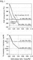
- FIG. 1 illustrates the relationship between a melt temperature or an Fe concentration in a liquid phase and a solid phase ratio.
- the melting point of an Fe compound is low, and the Fe concentration after the removal remains at 0.681%.
- the melting point of an Fe compound is high, and the crystallization temperature of an Al phase ( ⁇ -Al) is low.
- the Fe concentration in a (second) melt after the removal of an unmelted solid such as an Fe compound or iron scrap can be significantly reduced to 0.302%.
- the Fe compound has a larger specific gravity than that of the melt and therefore settles out to a lower layer region of the melt, and the Fe compound and the melt can readily be separated.
- Fe as an impurity can be efficiently removed as the Fe compound. Moreover, even when the unmelted solid such as iron scrap comes into contact with the melt, Fe cannot be melted in the melt. An Al alloy melt (second melt) can therefore be obtained with a sufficiently reduced Fe concentration.
- the Fe compound as referred to in the present specification is not limited in its composition and form, provided that the Fe compound is a compound that contains Fe (e.g., an intermetallic compound that contains Fe).
- Representative Fe compounds include, for example, Al 9 Fe 2 Si 2 and Al 5 FeSi.
- FIG. 2 illustrates a partially enlarged Al-Si-Cu ternary phase diagram (liquid phase surface). Isothermal lines in FIG. 2 indicate the temperature at which a Si phase or an ⁇ -Al phase crystallizes as the primary crystal. In the composition on the ⁇ -Al+Si eutectic line, the ⁇ -Al phase and the Si phase simultaneously crystallize. As apparent from FIG. 2 , it is found that when the Cu concentration is changed from 3% to 10% in a 12%Si alloy melt, for example, Si preferentially crystallizes prior to the ⁇ -Al phase. The crystallized Si has a lower specific gravity than that of the melt and therefore floats in an upper layer region of the melt and can readily be separated. Thus, according to the present invention, excess Si can be efficiently removed, and the Al alloy melt (second melt) can be obtained with a reduced Si concentration.
- FIG. 3 illustrates the relationship between the Mn concentration and the critical concentration of Fe that can be melted in the melt (simply referred to as a "critical Fe concentration” or an "Fe concentration).
- critical Fe concentration or an "Fe concentration
- the Fe concentration in the melt can be further reduced by adding Mn to the melt in addition to Cu.
- the Mn concentration in the first melt is preferably set to, for example, 1% or more in an embodiment or 2% or more in another embodiment.
- the Cu concentration in the first melt is preferably set to 4% or more in an embodiment or 7% or more in another embodiment.
- the first melt obtained in the preparation step is held at a temperature at which Si and an Fe compound crystallize and the solid phase and the remaining liquid phase can be separated.
- the first melt may therefore be held at a temperature (separation temperature) within a temperature range in which Al does not crystallize but Si and an Fe compound crystallize.
- the separation temperature can be adjusted in accordance with the alloy composition of the first melt and is preferably set to, for example, (crystallization start temperature of ⁇ -Al)+(5°C to 30°C in an embodiment or 10°C to 20°C in another embodiment). More specifically, the separation temperature may be adjusted within a range of, for example, 540°C to 570°C in an embodiment or 550°C to 560°C in another embodiment.
- the holding step is preferably a slow cooling step in order to promote crystallization of Si and an Fe compound and their grain growth.
- the slow cooling is preferably performed at a cooling rate of 0.1°C/min to 2°C/min in an embodiment or 0.5°C/min to 1°C/min in another embodiment.
- the cooling rate as referred to herein is an average value obtained by dividing the temperature difference by the required time from the start of the holding step to the start of the subsequent extraction step.
- a holding time may be provided at a temperature within a temperature range from the initial temperature of the first melt to the separation temperature to promote the crystallization of Si and an Fe compound and to coarsen the Si and the Fe compound.
- the holding step in this case is a slow cooling step in which the cooling rate is more reduced in accordance with the holding time.
- the second melt By removing at least part of the Si and Fe compound crystallized from the first melt, the second melt can be obtained with reduced concentrations of Si and Fe. Extraction of the second melt can also be performed by removing the Si and Fe compound as solid phases from a crucible filled with the melt using a filter or the like.
- the crystallized Si (solid phase Si) having a specific gravity smaller than that of the melt tends to float in the melt upper layer while the Fe compound having a specific gravity larger than that of the melt tends to settle out to the melt lower layer. Extraction of the second melt may therefore be performed by taking out only the melt having reduced concentrations of Si and Fe from the middle (middle layer region) of the crucible filled with the melt.
- this step of extracting the second melt in the liquid phase may be performed at a temperature within a temperature range similar to that of the separation temperature.
- the extraction step may preferably include removing a residual solid that was not melted in the preparation step (e.g., iron scrap and the like contained in part of the Al alloy raw material).
- the extracted second melt is preferably used in a casting step or the like without being solidified.
- the second melt may be further refined before casting and/or adjusted to a desired component by adding pure Al (virgin ingot) and/or an alloy source (a component adjustment step).
- the second melt may also be once solidified and then supplied as a recycled ingot to be the raw material of a cast material or a wrought material.
- Raw materials were put in a graphite crucible (height 158 mm ⁇ upper diameter 120 mm ⁇ bottom diameter 80 mm, upper thickness 11 mm) and heated to 700°C to melt.
- the raw materials were compounded such that the alloy composition of the melt would be Al-12%Si-1%Fe-10%Cu.
- an initial melt (first melt) of about 1.5 kg was prepared.
- the initial melt was cooled in a furnace to 560°C (crystallization start temperature of ⁇ -Al plus 5°C) for 90 minutes. From the melt after cooling, the melt in each region of the upper layer part, middle layer part, and lower layer part was extracted and solidified as follows.
- the upper layer part (surface layer portion having a thickness of about 10 mm) of the melt was collected with a spoon and naturally solidified in a mold for analysis ( ⁇ 40 mm ⁇ 30mm). Sample 1 for upper layer part analysis was thus obtained.
- the melt after removing the upper layer part was poured into a test material production mold (about 30 mm ⁇ 40 mm ⁇ 200 mm) for sampling a mold test piece as described in JIS H5202: 2010 and naturally solidified. Sample 2 for middle layer part analysis was thus obtained.
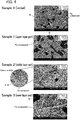
- the Si concentration (composition) is higher and a larger amount of Si crystallizes in Sample 1 of the upper layer part than in Sample 0 of the initial state.
- Sample 3 of the lower layer part it is found that a large amount of an Fe compound crystallizes and the Fe concentration (composition) is high.
- Sample 2 which is the middle between them, it is found that there is almost no crystallization of Si and a Fe compound and the Si concentration and the Fe concentration are significantly reduced. Specifically, in the middle layer part, the Si concentration is reduced from 13.3% (initial) to 9.8% and the Fe concentration is reduced from 1.4% (initial) to 0.76%.
- a recycled Al alloy (melt) having a sufficiently reduced Si concentration and a sufficiently reduced Fe concentration can be obtained from an Al alloy raw material such as scrap.
Landscapes
- Engineering & Computer Science (AREA)
- Chemical & Material Sciences (AREA)
- Manufacturing & Machinery (AREA)
- Materials Engineering (AREA)
- Mechanical Engineering (AREA)
- Metallurgy (AREA)
- Organic Chemistry (AREA)
- Life Sciences & Earth Sciences (AREA)
- Environmental & Geological Engineering (AREA)
- General Life Sciences & Earth Sciences (AREA)
- Geology (AREA)
- Manufacture And Refinement Of Metals (AREA)
Abstract
Description
- The present invention relates to a method of obtaining a recycled Al alloy from scrap and the like.
- With the recent rise in environmental awareness and the like, various structural members and devices are being reduced in weight, and the used amount of aluminum alloy (simply referred to as "Al alloy") is increasing. A large amount of energy is required for the production (smelting) of new Al. In contrast, the energy required for remelting scrap of Al alloy is very little. It is thus desired to recycle scrap of Al alloy and use the recycled Al alloy.
- When Al alloy scrap is remelted, some elements such as Fe, Si, Cu, Mg, and Zn are usually mixed in the melt. To obtain the recycled Al alloy from scrap, unnecessary elements (impurity elements) or excess elements have to be removed. Relevant descriptions of methods for removing such elements are found in the following documents.
-
- [Patent Document 1]
US2464610B - [Patent Document 2]
US5741348B - [Patent Document 3]
JP2002-155322A - [Patent Document 4]
US4734127B - [Patent Document 5]
WO2013/168213 - [Patent Document 6]
WO2013/168214 - [Non-Patent Documents]
-
- [Non-Patent Document 1] Furukawa Electric Review, No. 104 (July 1999) 25-30
- [Non-Patent Document 2] Metallurgical Transactions 5 (1974) 785-787
- [Non-Patent Document 3] Material Transactions, JIM.38 (1997) 622-699
-
Patent Documents Patent Document 1 discloses adding Cr, Mn, and Co to an Al-(11.6-13.5)%Si-(0.8-9)%Fe alloy to crystallize an Fe-based intermetallic compound to reduce the amount of Fe in the melt.Patent Document 2 discloses adding Mn to an Al-(0-12)%Si-(0.49-2.1)%Fe-(0.37-1.91)%Mn alloy (Cr<0.4%, Ti<0.41%, Zr<0.26%, Mo<0.01%) to reduce the amount of Fe. However, when Si is 8% or less, 0.5% or more of Fe remains in the melt even after the removal of the intermetallic compound, and the removal efficiency is low.Non-Patent Document 1 reports that Fe and Mn cannot be simultaneously reduced to 0.3% or less from an Al alloy melt (Fe<1.5%, Mn<1.5%, Si<10%, Cr<0.2%, Mg<1%, Cu<1%, Ti<0.1%, Ni<1%, Zn<1%). Unless otherwise stated, "%" as referred to in the present specification means mass%. -
Patent Documents 3 to 6 andNon-Patent Documents Document 1 discloses pressurizing the semi-solidified melt to remove the residual liquid phase. Non-PatentDocument 2 discloses stirring the semi-solidified melt to spheroidize the Al crystallized substance and separating it from the residual liquid phase. Such methods require cooling the melt until the Al phase crystallizes, and the energy loss is thus large. - Non-Patent
Document 3 relates to a semi-molten refining method that includes heating an Al alloy (solid) to a semi-molten state to separate it into a liquid phase and residual Al crystals and removing impurities exceeding the solid solubility limit of the Al phase. Specifically, Non-PatentDocument 3 discloses pressurizing an Al-8.39%Si-0.06%Mn-0.05%Mg alloy in a semi-molten state to separate a liquid phase and obtaining an Al-0.96%Si-1.14%Mn-1.56%Mg alloy from the residue. In this method, it is difficult to remove Fe and Mn via an intermetallic compound. Moreover, the amount of residual Al crystals in the semi-molten state depends on the temperature and, therefore, alloy compositions for which this method can be used are limited. - Other methods than the above-described methods for removing impurities from an Al alloy include a zone melting method that includes partially heating/melting an ingot from its one end side to collect impurities on the other end side and enhancing the purity on the one end side from which the heating was started.
- The present invention has been made in view of such circumstances and an object of the present invention is to provide a recycling method for an aluminum alloy capable of obtaining an Al alloy (melt) from which Fe and/or Si are efficiently removed by a different method than the conventional methods.
- As a result of intensive studies to achieve the above object, the present inventors have succeeded in the removal (concentration reduction) of Si and Fe contained in an Al alloy melt through melting scrap and the like into the melt and adding Cu to the melt to put the melt into a hypereutectic composition of Cu and Si (composition range in which Si phases crystallize from the melt prior to α-Al phases when the melt is cooled). Developing this achievement, the present inventors have accomplished the present invention, which will be described below.
-
- (1) The present invention provides a recycling method for an aluminum alloy, comprising: a preparation step of melting at least part of an Al alloy raw material to prepare a first melt having a hypereutectic composition of Cu and Si; a holding step of holding the first melt at a separation temperature at which Si and an Fe compound crystallize; and an extraction step of extracting a second melt obtained by removing at least part of an unmelted solid, such as iron scrap or the Si and the Fe compound which crystallize from the first melt.
- (2) According to the recycling method for an aluminum alloy (simply referred to as a "recycling method") of the present invention, the crystallized Si and the crystallized iron compound (simply referred to as an "Fe compound") can readily be removed from the first melt obtained by melting the Al alloy raw material, and the recycled Al alloy can be efficiently obtained with sufficiently reduced concentrations of the crystallized Si and the crystallized Fe compound. Moreover, the recycled Al alloy is obtained in a liquid-phase state (i.e., a melt state) rather than in a solid-phase state and can therefore be shipped or reused (such as casted) as a recycled bare metal without any processing such as remelting.
- Unless otherwise stated, a numerical range "x to y" as referred to in the present specification includes the lower limit x and the upper limit y. Any numerical value included in various numerical values or numerical ranges described in the present specification may be selected or extracted as a new lower or upper limit, and any numerical range such as "a to b" can thereby be newly provided using such a new lower or upper limit.
-
-
FIG. 1 is a graph illustrating the relationship between a melt temperature or an Fe concentration in a liquid phase and a solid phase ratio. -
FIG. 2 is a ternary phase diagram of Al-Si-Cu. -
FIG. 3 is a graph illustrating the relationship between an initial Mn concentration and a reduced critical Fe concentration. -
FIG. 4 is a set of SEM images of metallographic structures according to respective samples. - One or more features freely selected from the present specification can be added to the above-described features of the present invention. In the content described in the present specification, methodological features can even be features regarding a product (such as a recycled Al alloy or a recycled Al alloy member).
- The principle of Fe and Si removal by the recycling method of the present invention will be described with reference to
FIGS. 1 to 3. FIGS. 1 to 3 illustrate the results of calculation using analysis software ("Thermo-Calc" available from Thermo-Calc Software AB).FIGS. 1 and3 are based on the Scheil calculation andFIG. 2 is based on the equilibrium calculation. - For an Al-12%Si-1%Fe-3%Cu alloy melt (simply referred to as "3%Cu melt") and an Al-12%Si-1%Fe-10%Cu alloy melt (simply referred to as "10%Cu melt"),
FIG. 1 illustrates the relationship between a melt temperature or an Fe concentration in a liquid phase and a solid phase ratio. - As apparent from
FIG. 1 , in the case of the 3%Cu melt, the melting point of an Fe compound (intermetallic compound) is low, and the Fe concentration after the removal remains at 0.681%. On the other hand, in the case of the 10%Cu melt, the melting point of an Fe compound is high, and the crystallization temperature of an Al phase (α-Al) is low. For this reason, the Fe concentration in a (second) melt after the removal of an unmelted solid such as an Fe compound or iron scrap can be significantly reduced to 0.302%. The Fe compound has a larger specific gravity than that of the melt and therefore settles out to a lower layer region of the melt, and the Fe compound and the melt can readily be separated. Thus, according to the present invention, Fe as an impurity can be efficiently removed as the Fe compound. Moreover, even when the unmelted solid such as iron scrap comes into contact with the melt, Fe cannot be melted in the melt. An Al alloy melt (second melt) can therefore be obtained with a sufficiently reduced Fe concentration. - The Fe compound as referred to in the present specification is not limited in its composition and form, provided that the Fe compound is a compound that contains Fe (e.g., an intermetallic compound that contains Fe). Representative Fe compounds include, for example, Al9Fe2Si2 and Al5FeSi.
-
FIG. 2 illustrates a partially enlarged Al-Si-Cu ternary phase diagram (liquid phase surface). Isothermal lines inFIG. 2 indicate the temperature at which a Si phase or an α-Al phase crystallizes as the primary crystal. In the composition on the α-Al+Si eutectic line, the α-Al phase and the Si phase simultaneously crystallize. As apparent fromFIG. 2 , it is found that when the Cu concentration is changed from 3% to 10% in a 12%Si alloy melt, for example, Si preferentially crystallizes prior to the α-Al phase. The crystallized Si has a lower specific gravity than that of the melt and therefore floats in an upper layer region of the melt and can readily be separated. Thus, according to the present invention, excess Si can be efficiently removed, and the Al alloy melt (second melt) can be obtained with a reduced Si concentration. - For Al-12%Si-1%Fe-(0-5)%Mn-(3-15)%Cu alloy melts having different initial Mn concentrations and Cu concentrations,
FIG. 3 illustrates the relationship between the Mn concentration and the critical concentration of Fe that can be melted in the melt (simply referred to as a "critical Fe concentration" or an "Fe concentration). As apparent fromFIG. 3 , it is found that as the Mn concentration increases, the critical Fe concentration (so-called solubility limit) decreases and the Fe concentration in the melt can be reduced. - Moreover, as the Cu concentration increases, the critical Fe concentration significantly decreases. It is thus found that the Fe concentration in the melt can be further reduced by adding Mn to the melt in addition to Cu. In consideration of this, the Mn concentration in the first melt is preferably set to, for example, 1% or more in an embodiment or 2% or more in another embodiment. Additionally or alternatively, the Cu concentration in the first melt is preferably set to 4% or more in an embodiment or 7% or more in another embodiment.
-
- (1) At least part of an Al alloy raw material is melted to prepare a first melt having desired concentrations of Cu and Si. In this preparation, after analyzing the melt component of the melted Al alloy raw material, at least an appropriate amount of a Cu source raw material (e.g., pure Cu, a Cu alloy, or a Cu compound) may be added to the melt to adjust the composition of the first melt. The melting temperature (first melt temperature) may be a temperature at which the raw material as a whole is melted, but when Al alloy scrap is used, the melting temperature may be a temperature at which iron scrap or the like remains unmelted so as to be readily separated. For example, the melting temperature may be set to about 540°C to 750°C in an embodiment or about 580°C to 610°C in another embodiment.
In the preparation step, it is sufficient that the melt (first melt) is finally obtained to have a hypereutectic composition of Cu and Si. The "hypereutectic composition" as referred to in the present specification falls within a composition range in which the Si phase crystallizes prior to the α-Al phase when the melt is cooled. InFIG. 2 , the Si crystallization region corresponds to the hypereutectic composition. The hypereutectic composition may be expressed by a formula ([Cu]≥-0.15[Si]2-1.11[Si]+37.7). The α-Al crystallization region in the figure refers to a composition range in which the α-Al phase crystallizes prior to the Si phase, which is called a "hypoeutectic composition." - (2) It is preferred to mainly use Al alloy scrap as the Al alloy raw material. The Al alloy raw material may be a cast material or may also be a wrought material. In the recycling method of the present invention, however, the Al alloy melt (second melt) which contains Si within a desired range is extracted from the first melt having a hypereutectic composition of Si. Usually, therefore, scrap of an Al alloy cast material that contains a large amount of Si is preferred as the Al alloy raw material. The Al alloy cast material may be any of cast materials such as those obtained by die casting, gravity casting, and low-pressure casting. In an embodiment, the Al alloy raw material may be combined with a member or the like composed of a metal other than an Al alloy (e.g., a steel material).
- The first melt obtained in the preparation step is held at a temperature at which Si and an Fe compound crystallize and the solid phase and the remaining liquid phase can be separated. In this operation, if the first melt is cooled to a temperature at which α-Al crystallizes, it becomes difficult to efficiently separate the crystallized Si and the crystallized Fe compound. The first melt may therefore be held at a temperature (separation temperature) within a temperature range in which Al does not crystallize but Si and an Fe compound crystallize. The separation temperature can be adjusted in accordance with the alloy composition of the first melt and is preferably set to, for example, (crystallization start temperature of α-Al)+(5°C to 30°C in an embodiment or 10°C to 20°C in another embodiment). More specifically, the separation temperature may be adjusted within a range of, for example, 540°C to 570°C in an embodiment or 550°C to 560°C in another embodiment.
- The holding step is preferably a slow cooling step in order to promote crystallization of Si and an Fe compound and their grain growth. For example, the slow cooling is preferably performed at a cooling rate of 0.1°C/min to 2°C/min in an embodiment or 0.5°C/min to 1°C/min in another embodiment. The cooling rate as referred to herein is an average value obtained by dividing the temperature difference by the required time from the start of the holding step to the start of the subsequent extraction step. In an embodiment, a holding time may be provided at a temperature within a temperature range from the initial temperature of the first melt to the separation temperature to promote the crystallization of Si and an Fe compound and to coarsen the Si and the Fe compound. The holding step in this case is a slow cooling step in which the cooling rate is more reduced in accordance with the holding time.
- By removing at least part of the Si and Fe compound crystallized from the first melt, the second melt can be obtained with reduced concentrations of Si and Fe. Extraction of the second melt can also be performed by removing the Si and Fe compound as solid phases from a crucible filled with the melt using a filter or the like. Here, the crystallized Si (solid phase Si) having a specific gravity smaller than that of the melt tends to float in the melt upper layer while the Fe compound having a specific gravity larger than that of the melt tends to settle out to the melt lower layer. Extraction of the second melt may therefore be performed by taking out only the melt having reduced concentrations of Si and Fe from the middle (middle layer region) of the crucible filled with the melt. In any case, this step of extracting the second melt in the liquid phase may be performed at a temperature within a temperature range similar to that of the separation temperature. The extraction step may preferably include removing a residual solid that was not melted in the preparation step (e.g., iron scrap and the like contained in part of the Al alloy raw material).
- The extracted second melt is preferably used in a casting step or the like without being solidified. The second melt may be further refined before casting and/or adjusted to a desired component by adding pure Al (virgin ingot) and/or an alloy source (a component adjustment step). As will be understood, the second melt may also be once solidified and then supplied as a recycled ingot to be the raw material of a cast material or a wrought material.
- On the assumption of the first melt as referred to in the present invention, an Al alloy melt containing Si, Fe, and Cu was prepared. Metallographic structure observation and component measurement were performed using a sample obtained by solidifying the melt extracted from each layer region. The present invention will be described in more detail with reference to such specific examples.
- Raw materials were put in a graphite crucible (height 158 mm×upper diameter 120 mm×bottom diameter 80 mm,
upper thickness 11 mm) and heated to 700°C to melt. The raw materials were compounded such that the alloy composition of the melt would be Al-12%Si-1%Fe-10%Cu. Thus, an initial melt (first melt) of about 1.5 kg was prepared. - Part of the initial melt was poured into a mold for analysis (ϕ40 mm×30 mm) and placed to be cooled and naturally solidified in a room.
Sample 0 for initial melt analysis was thus obtained. - The initial melt was cooled in a furnace to 560°C (crystallization start temperature of α-Al plus 5°C) for 90 minutes. From the melt after cooling, the melt in each region of the upper layer part, middle layer part, and lower layer part was extracted and solidified as follows.
- The upper layer part (surface layer portion having a thickness of about 10 mm) of the melt was collected with a spoon and naturally solidified in a mold for analysis (ϕ40 mm × 30mm).
Sample 1 for upper layer part analysis was thus obtained. - The melt after removing the upper layer part was poured into a test material production mold (about 30 mm×40 mm×200 mm) for sampling a mold test piece as described in JIS H5202: 2010 and naturally solidified.
Sample 2 for middle layer part analysis was thus obtained. - The solidified part remaining at the bottom of the crucible after pouring the melt of the middle layer part was cooled in the room with the crucible and solidified.
Sample 3 for lower layer part analysis was thus obtained. - The cross section of each sample was observed for its structure with a scanning electron microscope (SEM), and the Si concentration and the Fe concentration were analyzed with ICP emission spectrometry. The results are listed together in
FIG. 4 . The observation and analysis ofSamples 0 to 2 were performed on the center part (ϕ20 mm) of the horizontal cross section at the position of a height of 10 mm from the sample bottom surface. The observation and analysis ofSample 3 were performed on the center part (ϕ20 mm) of the horizontal cross section at the position of a height of 5 mm from the sample bottom surface. - As apparent from
FIG. 4 , it is found that the Si concentration (composition) is higher and a larger amount of Si crystallizes inSample 1 of the upper layer part than inSample 0 of the initial state. InSample 3 of the lower layer part, it is found that a large amount of an Fe compound crystallizes and the Fe concentration (composition) is high. InSample 2, which is the middle between them, it is found that there is almost no crystallization of Si and a Fe compound and the Si concentration and the Fe concentration are significantly reduced. Specifically, in the middle layer part, the Si concentration is reduced from 13.3% (initial) to 9.8% and the Fe concentration is reduced from 1.4% (initial) to 0.76%. - From the above, it has been confirmed that according to the recycling method of the present invention, a recycled Al alloy (melt) having a sufficiently reduced Si concentration and a sufficiently reduced Fe concentration can be obtained from an Al alloy raw material such as scrap.
Claims (6)
- A recycling method for an aluminum alloy, comprising:a preparation step of melting at least part of an Al alloy raw material to prepare a first melt having a hypereutectic composition of Cu and Si;a holding step of holding the first melt at a separation temperature at which Si and an Fe compound crystallize; andan extraction step of extracting a second melt obtained by removing at least part of the Si and Fe compound crystallized from the first melt.
- The recycling method for an aluminum alloy according to claim 1, wherein the first melt contains 1 mass% or more of Mn with respect to the first melt as a whole.
- The recycling method for an aluminum alloy according to claim 1 or 2, wherein the first melt contains 4 mass% or more of Cu with respect to the first melt as a whole.
- The recycling method for an aluminum alloy according to any one of claims 1 to 3, wherein the first melt contains 11 mass% or more of Si with respect to the first melt as a whole.
- The recycling method for an aluminum alloy according to any one of claims 1 to 4, wherein the Al alloy raw material contains scrap of an Al alloy cast material.
- The recycling method for an aluminum alloy according to any one of claims 1 to 5, wherein the holding step includes cooling at a cooling rate of 0.1°C/min to 2°C/min.
Applications Claiming Priority (2)
| Application Number | Priority Date | Filing Date | Title |
|---|---|---|---|
| JP2017203362A JP6667485B2 (en) | 2017-10-20 | 2017-10-20 | Recycling method of Al alloy |
| PCT/JP2018/032281 WO2019077892A1 (en) | 2017-10-20 | 2018-08-31 | Al ALLOY RECOVERY METHOD |
Publications (3)
| Publication Number | Publication Date |
|---|---|
| EP3663419A1 true EP3663419A1 (en) | 2020-06-10 |
| EP3663419A4 EP3663419A4 (en) | 2021-01-13 |
| EP3663419B1 EP3663419B1 (en) | 2022-02-09 |
Family
ID=66173666
Family Applications (1)
| Application Number | Title | Priority Date | Filing Date |
|---|---|---|---|
| EP18868910.3A Active EP3663419B1 (en) | 2017-10-20 | 2018-08-31 | Al alloy recovery method |
Country Status (3)
| Country | Link |
|---|---|
| EP (1) | EP3663419B1 (en) |
| JP (1) | JP6667485B2 (en) |
| WO (1) | WO2019077892A1 (en) |
Families Citing this family (12)
| Publication number | Priority date | Publication date | Assignee | Title |
|---|---|---|---|---|
| JP6800128B2 (en) * | 2017-10-20 | 2020-12-16 | 株式会社豊田中央研究所 | How to regenerate Al alloy |
| CN110117718B (en) * | 2019-05-15 | 2020-07-24 | 东北大学 | Method for smelting and preparing ferro-silicon-aluminum by using waste refractory material as raw material in electric arc furnace |
| CN110029227B (en) * | 2019-05-15 | 2020-01-07 | 东北大学 | Method for producing Al-Si-Fe by using waste refractory material as raw material by plasma jet feeding |
| CN110004300B (en) * | 2019-05-15 | 2020-03-20 | 东北大学 | Method for preparing ferrosilicon alloy by using aluminum ash as raw material through plasma jet feeding |
| CN110129565B (en) * | 2019-05-15 | 2020-03-20 | 东北大学 | Method for preparing ferrosilicon alloy by feeding aluminum ash as raw material through hollow electrode |
| CN111020255B (en) * | 2019-12-11 | 2021-06-18 | 苏州大学 | Sedimentation separation method of Fe element in aluminum alloy scrap melt |
| CN113913621B (en) * | 2020-11-13 | 2023-09-15 | 内蒙古君成科技有限公司 | Method for preparing aluminum-silicon-iron alloy by using high-aluminum gangue and purifying in grading manner |
| JP2023102012A (en) * | 2022-01-11 | 2023-07-24 | 株式会社Uacj | Metal refining method and metal refining apparatus |
| CN116790896A (en) * | 2023-07-04 | 2023-09-22 | 鹰普航空科技有限公司 | Process for improving mechanical properties of ZL101A aluminum alloy castings |
| CN116904796B (en) * | 2023-07-17 | 2026-04-10 | 湖南江滨机器(集团)有限责任公司 | A method for reducing iron content in aluminum-silicon alloys |
| CN117845089A (en) * | 2023-12-29 | 2024-04-09 | 中铝材料应用研究院有限公司 | A method for removing Fe element from cast aluminum alloy |
| CN120210544B (en) * | 2025-03-12 | 2026-01-09 | 广西广投高纯铝科技有限公司 | A method for preparing 5N high-purity aluminum |
Family Cites Families (17)
| Publication number | Priority date | Publication date | Assignee | Title |
|---|---|---|---|---|
| US2464610A (en) | 1940-07-08 | 1949-03-15 | Spolek | Method for producing aluminumsilicon alloys |
| US3374089A (en) * | 1965-02-26 | 1968-03-19 | Reynolds Metals Co | Centrifugal separation |
| US3537695A (en) * | 1968-01-19 | 1970-11-03 | Reynolds Metals Co | Apparatus for centrifuging |
| US3900313A (en) * | 1972-09-18 | 1975-08-19 | Hubert Martin | Process for producing die-casting alloys from aluminum scrap |
| JPS516810A (en) * | 1974-07-09 | 1976-01-20 | Mitsubishi Chem Ind | Aruminiumu mataha aruminiumugokinchunotetsuno jokyohoho |
| US4734127A (en) | 1984-10-02 | 1988-03-29 | Nippon Light Metal Co., Ltd. | Process and apparatus for refining aluminum |
| DE3791001T1 (en) * | 1987-08-25 | 1989-09-07 | Dn Metall Inst | METHOD FOR REFINING ALUMINUM ALLOYS |
| JPH05295466A (en) * | 1992-04-17 | 1993-11-09 | Nippon Light Metal Co Ltd | Method and apparatus for separating impurities from molten aluminum |
| JP3329013B2 (en) * | 1993-09-02 | 2002-09-30 | 日本軽金属株式会社 | Continuous refining method and apparatus for Al-Si aluminum scrap |
| JPH0873959A (en) * | 1994-08-31 | 1996-03-19 | Nippon Light Metal Co Ltd | Aluminum refining method and apparatus |
| JP3237438B2 (en) * | 1995-01-26 | 2001-12-10 | 日本軽金属株式会社 | Purification method of aluminum scrap |
| NL1000456C2 (en) | 1995-05-31 | 1996-12-03 | Hoogovens Aluminium Bv | Process for refining an aluminum scrap melt, and aluminum alloy from refined aluminum scrap. |
| JP3485086B2 (en) | 2000-11-15 | 2004-01-13 | 日本軽金属株式会社 | Method and apparatus for purifying aluminum or aluminum alloy |
| DE60104114T2 (en) * | 2001-09-03 | 2005-08-18 | Corus Technology Bv | Process for cleaning an aluminum alloy |
| GB2396310A (en) * | 2002-12-21 | 2004-06-23 | Foseco Int | Rotary device with vanes for dispersing a gas in a molten metal |
| JP5733474B2 (en) | 2012-05-07 | 2015-06-10 | 日本軽金属株式会社 | Aluminum refining apparatus and aluminum refining method |
| CN104145033A (en) | 2012-05-07 | 2014-11-12 | 日本轻金属株式会社 | Aluminum refining apparatus and aluminum refining method |
-
2017
- 2017-10-20 JP JP2017203362A patent/JP6667485B2/en active Active
-
2018
- 2018-08-31 EP EP18868910.3A patent/EP3663419B1/en active Active
- 2018-08-31 WO PCT/JP2018/032281 patent/WO2019077892A1/en not_active Ceased
Also Published As
| Publication number | Publication date |
|---|---|
| WO2019077892A1 (en) | 2019-04-25 |
| EP3663419A4 (en) | 2021-01-13 |
| JP6667485B2 (en) | 2020-03-18 |
| EP3663419B1 (en) | 2022-02-09 |
| JP2019077894A (en) | 2019-05-23 |
Similar Documents
| Publication | Publication Date | Title |
|---|---|---|
| EP3663419B1 (en) | Al alloy recovery method | |
| Liang et al. | Effect of cooling rate on grain refinement of cast aluminium alloys | |
| US20080299001A1 (en) | Aluminum alloy formulations for reduced hot tear susceptibility | |
| Qin et al. | Microstructure evolution of in situ Mg2Si/Al–Si–Cu composite in semisolid remelting processing | |
| US20150218673A1 (en) | Al-nb-b master alloy for grain refining | |
| EP2783020B1 (en) | Grain refinement, aluminium foundry alloys | |
| Chen et al. | Effect of strontium and melt purification on the solidification microstructure of hypereutectic Al-Si alloys | |
| JP3329013B2 (en) | Continuous refining method and apparatus for Al-Si aluminum scrap | |
| Sanchez et al. | High-throughput CALPHAD-guided design and experimental study on the development of a novel multicomponent as-cast Al-Si-Cu-Zn-Fe-Mn-Mg based alloy through the direct melting of post-consumer scrap | |
| JP7123834B2 (en) | Impurity removal method | |
| Rathinasuriyan et al. | Reducing iron content from aluminium molten bath through filter bag, centrifugal separation and flux refining method | |
| Qin et al. | Effect of holding temperature on semisolid microstructure of Mg2Si/Al composite | |
| JP6800128B2 (en) | How to regenerate Al alloy | |
| Zhang et al. | Effect of ultrasonic treatment on formation of iron-containing intermetallic compounds in Al-Si alloys | |
| Liu et al. | EPMA analysis of calcium-rich compounds in near eutectic Al–Si alloys | |
| US20220106666A1 (en) | Recycling method for aluminum alloy | |
| JP7423495B2 (en) | Impurity removal method | |
| Das | Microstructure Evolution during Cooling Slope Rheoprocessing of Novel Al-15Mg2Si-4.5 Si Composite | |
| Ma et al. | Modification of Mg2Si morphology in Mg–9% Al–0.7% Si alloy by the SIMA process | |
| Szymczak et al. | Hypoeutectic silumin to pressure die casting with vanadium and tungsten | |
| JP7414592B2 (en) | Al alloy regeneration method | |
| JP2019077895A (en) | REGENERATION METHOD OF Al ALLOY | |
| Spacil et al. | Effect of Eu and P additions with Ta grain refiner on the solidification microstructure of Al-7Si-0.3 Mg alloys | |
| US20250051880A1 (en) | Method for producing refined aluminum alloy | |
| US20240167122A1 (en) | Selective Removal of Impurities from Molten Aluminum |
Legal Events
| Date | Code | Title | Description |
|---|---|---|---|
| STAA | Information on the status of an ep patent application or granted ep patent |
Free format text: STATUS: THE INTERNATIONAL PUBLICATION HAS BEEN MADE |
|
| PUAI | Public reference made under article 153(3) epc to a published international application that has entered the european phase |
Free format text: ORIGINAL CODE: 0009012 |
|
| STAA | Information on the status of an ep patent application or granted ep patent |
Free format text: STATUS: REQUEST FOR EXAMINATION WAS MADE |
|
| 17P | Request for examination filed |
Effective date: 20200302 |
|
| AK | Designated contracting states |
Kind code of ref document: A1 Designated state(s): AL AT BE BG CH CY CZ DE DK EE ES FI FR GB GR HR HU IE IS IT LI LT LU LV MC MK MT NL NO PL PT RO RS SE SI SK SM TR |
|
| AX | Request for extension of the european patent |
Extension state: BA ME |
|
| A4 | Supplementary search report drawn up and despatched |
Effective date: 20201214 |
|
| RIC1 | Information provided on ipc code assigned before grant |
Ipc: C22C 21/02 20060101ALN20201208BHEP Ipc: C22B 9/10 20060101ALI20201208BHEP Ipc: C22B 21/06 20060101AFI20201208BHEP Ipc: C22B 7/00 20060101ALI20201208BHEP |
|
| DAV | Request for validation of the european patent (deleted) | ||
| DAX | Request for extension of the european patent (deleted) | ||
| STAA | Information on the status of an ep patent application or granted ep patent |
Free format text: STATUS: EXAMINATION IS IN PROGRESS |
|
| 17Q | First examination report despatched |
Effective date: 20210610 |
|
| GRAP | Despatch of communication of intention to grant a patent |
Free format text: ORIGINAL CODE: EPIDOSNIGR1 |
|
| STAA | Information on the status of an ep patent application or granted ep patent |
Free format text: STATUS: GRANT OF PATENT IS INTENDED |
|
| RIC1 | Information provided on ipc code assigned before grant |
Ipc: C22C 21/02 20060101ALN20211029BHEP Ipc: C22B 9/10 20060101ALI20211029BHEP Ipc: C22B 7/00 20060101ALI20211029BHEP Ipc: C22B 21/06 20060101AFI20211029BHEP |
|
| INTG | Intention to grant announced |
Effective date: 20211115 |
|
| RIN1 | Information on inventor provided before grant (corrected) |
Inventor name: UENO NORIYUKI Inventor name: HIBI KAZUMA Inventor name: KAWAHARA HIROSHI Inventor name: IWATA YASUSHI Inventor name: YAOKAWA JUN Inventor name: MINOURA TAKUMA |
|
| GRAS | Grant fee paid |
Free format text: ORIGINAL CODE: EPIDOSNIGR3 |
|
| GRAA | (expected) grant |
Free format text: ORIGINAL CODE: 0009210 |
|
| STAA | Information on the status of an ep patent application or granted ep patent |
Free format text: STATUS: THE PATENT HAS BEEN GRANTED |
|
| AK | Designated contracting states |
Kind code of ref document: B1 Designated state(s): AL AT BE BG CH CY CZ DE DK EE ES FI FR GB GR HR HU IE IS IT LI LT LU LV MC MK MT NL NO PL PT RO RS SE SI SK SM TR |
|
| REG | Reference to a national code |
Ref country code: GB Ref legal event code: FG4D |
|
| REG | Reference to a national code |
Ref country code: CH Ref legal event code: EP Ref country code: AT Ref legal event code: REF Ref document number: 1467546 Country of ref document: AT Kind code of ref document: T Effective date: 20220215 |
|
| REG | Reference to a national code |
Ref country code: IE Ref legal event code: FG4D |
|
| REG | Reference to a national code |
Ref country code: DE Ref legal event code: R096 Ref document number: 602018030750 Country of ref document: DE |
|
| REG | Reference to a national code |
Ref country code: LT Ref legal event code: MG9D |
|
| REG | Reference to a national code |
Ref country code: NL Ref legal event code: MP Effective date: 20220209 |
|
| REG | Reference to a national code |
Ref country code: AT Ref legal event code: MK05 Ref document number: 1467546 Country of ref document: AT Kind code of ref document: T Effective date: 20220209 |
|
| PG25 | Lapsed in a contracting state [announced via postgrant information from national office to epo] |
Ref country code: SE Free format text: LAPSE BECAUSE OF FAILURE TO SUBMIT A TRANSLATION OF THE DESCRIPTION OR TO PAY THE FEE WITHIN THE PRESCRIBED TIME-LIMIT Effective date: 20220209 Ref country code: RS Free format text: LAPSE BECAUSE OF FAILURE TO SUBMIT A TRANSLATION OF THE DESCRIPTION OR TO PAY THE FEE WITHIN THE PRESCRIBED TIME-LIMIT Effective date: 20220209 Ref country code: PT Free format text: LAPSE BECAUSE OF FAILURE TO SUBMIT A TRANSLATION OF THE DESCRIPTION OR TO PAY THE FEE WITHIN THE PRESCRIBED TIME-LIMIT Effective date: 20220609 Ref country code: NO Free format text: LAPSE BECAUSE OF FAILURE TO SUBMIT A TRANSLATION OF THE DESCRIPTION OR TO PAY THE FEE WITHIN THE PRESCRIBED TIME-LIMIT Effective date: 20220509 Ref country code: NL Free format text: LAPSE BECAUSE OF FAILURE TO SUBMIT A TRANSLATION OF THE DESCRIPTION OR TO PAY THE FEE WITHIN THE PRESCRIBED TIME-LIMIT Effective date: 20220209 Ref country code: LT Free format text: LAPSE BECAUSE OF FAILURE TO SUBMIT A TRANSLATION OF THE DESCRIPTION OR TO PAY THE FEE WITHIN THE PRESCRIBED TIME-LIMIT Effective date: 20220209 Ref country code: HR Free format text: LAPSE BECAUSE OF FAILURE TO SUBMIT A TRANSLATION OF THE DESCRIPTION OR TO PAY THE FEE WITHIN THE PRESCRIBED TIME-LIMIT Effective date: 20220209 Ref country code: ES Free format text: LAPSE BECAUSE OF FAILURE TO SUBMIT A TRANSLATION OF THE DESCRIPTION OR TO PAY THE FEE WITHIN THE PRESCRIBED TIME-LIMIT Effective date: 20220209 Ref country code: BG Free format text: LAPSE BECAUSE OF FAILURE TO SUBMIT A TRANSLATION OF THE DESCRIPTION OR TO PAY THE FEE WITHIN THE PRESCRIBED TIME-LIMIT Effective date: 20220509 |
|
| PG25 | Lapsed in a contracting state [announced via postgrant information from national office to epo] |
Ref country code: PL Free format text: LAPSE BECAUSE OF FAILURE TO SUBMIT A TRANSLATION OF THE DESCRIPTION OR TO PAY THE FEE WITHIN THE PRESCRIBED TIME-LIMIT Effective date: 20220209 Ref country code: LV Free format text: LAPSE BECAUSE OF FAILURE TO SUBMIT A TRANSLATION OF THE DESCRIPTION OR TO PAY THE FEE WITHIN THE PRESCRIBED TIME-LIMIT Effective date: 20220209 Ref country code: GR Free format text: LAPSE BECAUSE OF FAILURE TO SUBMIT A TRANSLATION OF THE DESCRIPTION OR TO PAY THE FEE WITHIN THE PRESCRIBED TIME-LIMIT Effective date: 20220510 Ref country code: FI Free format text: LAPSE BECAUSE OF FAILURE TO SUBMIT A TRANSLATION OF THE DESCRIPTION OR TO PAY THE FEE WITHIN THE PRESCRIBED TIME-LIMIT Effective date: 20220209 Ref country code: AT Free format text: LAPSE BECAUSE OF FAILURE TO SUBMIT A TRANSLATION OF THE DESCRIPTION OR TO PAY THE FEE WITHIN THE PRESCRIBED TIME-LIMIT Effective date: 20220209 |
|
| PG25 | Lapsed in a contracting state [announced via postgrant information from national office to epo] |
Ref country code: IS Free format text: LAPSE BECAUSE OF FAILURE TO SUBMIT A TRANSLATION OF THE DESCRIPTION OR TO PAY THE FEE WITHIN THE PRESCRIBED TIME-LIMIT Effective date: 20220609 |
|
| PG25 | Lapsed in a contracting state [announced via postgrant information from national office to epo] |
Ref country code: SM Free format text: LAPSE BECAUSE OF FAILURE TO SUBMIT A TRANSLATION OF THE DESCRIPTION OR TO PAY THE FEE WITHIN THE PRESCRIBED TIME-LIMIT Effective date: 20220209 Ref country code: SK Free format text: LAPSE BECAUSE OF FAILURE TO SUBMIT A TRANSLATION OF THE DESCRIPTION OR TO PAY THE FEE WITHIN THE PRESCRIBED TIME-LIMIT Effective date: 20220209 Ref country code: RO Free format text: LAPSE BECAUSE OF FAILURE TO SUBMIT A TRANSLATION OF THE DESCRIPTION OR TO PAY THE FEE WITHIN THE PRESCRIBED TIME-LIMIT Effective date: 20220209 Ref country code: EE Free format text: LAPSE BECAUSE OF FAILURE TO SUBMIT A TRANSLATION OF THE DESCRIPTION OR TO PAY THE FEE WITHIN THE PRESCRIBED TIME-LIMIT Effective date: 20220209 Ref country code: DK Free format text: LAPSE BECAUSE OF FAILURE TO SUBMIT A TRANSLATION OF THE DESCRIPTION OR TO PAY THE FEE WITHIN THE PRESCRIBED TIME-LIMIT Effective date: 20220209 Ref country code: CZ Free format text: LAPSE BECAUSE OF FAILURE TO SUBMIT A TRANSLATION OF THE DESCRIPTION OR TO PAY THE FEE WITHIN THE PRESCRIBED TIME-LIMIT Effective date: 20220209 |
|
| REG | Reference to a national code |
Ref country code: DE Ref legal event code: R097 Ref document number: 602018030750 Country of ref document: DE |
|
| PG25 | Lapsed in a contracting state [announced via postgrant information from national office to epo] |
Ref country code: AL Free format text: LAPSE BECAUSE OF FAILURE TO SUBMIT A TRANSLATION OF THE DESCRIPTION OR TO PAY THE FEE WITHIN THE PRESCRIBED TIME-LIMIT Effective date: 20220209 |
|
| PLBE | No opposition filed within time limit |
Free format text: ORIGINAL CODE: 0009261 |
|
| STAA | Information on the status of an ep patent application or granted ep patent |
Free format text: STATUS: NO OPPOSITION FILED WITHIN TIME LIMIT |
|
| 26N | No opposition filed |
Effective date: 20221110 |
|
| PG25 | Lapsed in a contracting state [announced via postgrant information from national office to epo] |
Ref country code: SI Free format text: LAPSE BECAUSE OF FAILURE TO SUBMIT A TRANSLATION OF THE DESCRIPTION OR TO PAY THE FEE WITHIN THE PRESCRIBED TIME-LIMIT Effective date: 20220209 |
|
| PG25 | Lapsed in a contracting state [announced via postgrant information from national office to epo] |
Ref country code: MC Free format text: LAPSE BECAUSE OF FAILURE TO SUBMIT A TRANSLATION OF THE DESCRIPTION OR TO PAY THE FEE WITHIN THE PRESCRIBED TIME-LIMIT Effective date: 20220209 |
|
| REG | Reference to a national code |
Ref country code: CH Ref legal event code: PL |
|
| GBPC | Gb: european patent ceased through non-payment of renewal fee |
Effective date: 20220831 |
|
| PG25 | Lapsed in a contracting state [announced via postgrant information from national office to epo] |
Ref country code: LU Free format text: LAPSE BECAUSE OF NON-PAYMENT OF DUE FEES Effective date: 20220831 Ref country code: LI Free format text: LAPSE BECAUSE OF NON-PAYMENT OF DUE FEES Effective date: 20220831 Ref country code: CH Free format text: LAPSE BECAUSE OF NON-PAYMENT OF DUE FEES Effective date: 20220831 |
|
| REG | Reference to a national code |
Ref country code: BE Ref legal event code: MM Effective date: 20220831 |
|
| PG25 | Lapsed in a contracting state [announced via postgrant information from national office to epo] |
Ref country code: IT Free format text: LAPSE BECAUSE OF FAILURE TO SUBMIT A TRANSLATION OF THE DESCRIPTION OR TO PAY THE FEE WITHIN THE PRESCRIBED TIME-LIMIT Effective date: 20220209 Ref country code: IE Free format text: LAPSE BECAUSE OF NON-PAYMENT OF DUE FEES Effective date: 20220831 Ref country code: FR Free format text: LAPSE BECAUSE OF NON-PAYMENT OF DUE FEES Effective date: 20220831 |
|
| PG25 | Lapsed in a contracting state [announced via postgrant information from national office to epo] |
Ref country code: BE Free format text: LAPSE BECAUSE OF NON-PAYMENT OF DUE FEES Effective date: 20220831 |
|
| PG25 | Lapsed in a contracting state [announced via postgrant information from national office to epo] |
Ref country code: GB Free format text: LAPSE BECAUSE OF NON-PAYMENT OF DUE FEES Effective date: 20220831 |
|
| PG25 | Lapsed in a contracting state [announced via postgrant information from national office to epo] |
Ref country code: CY Free format text: LAPSE BECAUSE OF FAILURE TO SUBMIT A TRANSLATION OF THE DESCRIPTION OR TO PAY THE FEE WITHIN THE PRESCRIBED TIME-LIMIT Effective date: 20220209 |
|
| PG25 | Lapsed in a contracting state [announced via postgrant information from national office to epo] |
Ref country code: MK Free format text: LAPSE BECAUSE OF FAILURE TO SUBMIT A TRANSLATION OF THE DESCRIPTION OR TO PAY THE FEE WITHIN THE PRESCRIBED TIME-LIMIT Effective date: 20220209 Ref country code: HU Free format text: LAPSE BECAUSE OF FAILURE TO SUBMIT A TRANSLATION OF THE DESCRIPTION OR TO PAY THE FEE WITHIN THE PRESCRIBED TIME-LIMIT; INVALID AB INITIO Effective date: 20180831 |
|
| PG25 | Lapsed in a contracting state [announced via postgrant information from national office to epo] |
Ref country code: TR Free format text: LAPSE BECAUSE OF FAILURE TO SUBMIT A TRANSLATION OF THE DESCRIPTION OR TO PAY THE FEE WITHIN THE PRESCRIBED TIME-LIMIT Effective date: 20220209 |
|
| PG25 | Lapsed in a contracting state [announced via postgrant information from national office to epo] |
Ref country code: MT Free format text: LAPSE BECAUSE OF FAILURE TO SUBMIT A TRANSLATION OF THE DESCRIPTION OR TO PAY THE FEE WITHIN THE PRESCRIBED TIME-LIMIT Effective date: 20220209 |
|
| PGFP | Annual fee paid to national office [announced via postgrant information from national office to epo] |
Ref country code: DE Payment date: 20250702 Year of fee payment: 8 |