EP3663388B1 - Vorrichtung für in-vitro-modellierung von in-vivo-geweben von organen - Google Patents
Vorrichtung für in-vitro-modellierung von in-vivo-geweben von organen Download PDFInfo
- Publication number
- EP3663388B1 EP3663388B1 EP20152403.0A EP20152403A EP3663388B1 EP 3663388 B1 EP3663388 B1 EP 3663388B1 EP 20152403 A EP20152403 A EP 20152403A EP 3663388 B1 EP3663388 B1 EP 3663388B1
- Authority
- EP
- European Patent Office
- Prior art keywords
- membrane
- culturing
- actuation
- chamber
- cells
- Prior art date
- Legal status (The legal status is an assumption and is not a legal conclusion. Google has not performed a legal analysis and makes no representation as to the accuracy of the status listed.)
- Active
Links
Images


Classifications
-
- C—CHEMISTRY; METALLURGY
- C12—BIOCHEMISTRY; BEER; SPIRITS; WINE; VINEGAR; MICROBIOLOGY; ENZYMOLOGY; MUTATION OR GENETIC ENGINEERING
- C12M—APPARATUS FOR ENZYMOLOGY OR MICROBIOLOGY; APPARATUS FOR CULTURING MICROORGANISMS FOR PRODUCING BIOMASS, FOR GROWING CELLS OR FOR OBTAINING FERMENTATION OR METABOLIC PRODUCTS, i.e. BIOREACTORS OR FERMENTERS
- C12M21/00—Bioreactors or fermenters specially adapted for specific uses
- C12M21/08—Bioreactors or fermenters specially adapted for specific uses for producing artificial tissue or for ex-vivo cultivation of tissue
-
- C—CHEMISTRY; METALLURGY
- C12—BIOCHEMISTRY; BEER; SPIRITS; WINE; VINEGAR; MICROBIOLOGY; ENZYMOLOGY; MUTATION OR GENETIC ENGINEERING
- C12M—APPARATUS FOR ENZYMOLOGY OR MICROBIOLOGY; APPARATUS FOR CULTURING MICROORGANISMS FOR PRODUCING BIOMASS, FOR GROWING CELLS OR FOR OBTAINING FERMENTATION OR METABOLIC PRODUCTS, i.e. BIOREACTORS OR FERMENTERS
- C12M25/00—Means for supporting, enclosing or fixing the microorganisms, e.g. immunocoatings
- C12M25/02—Membranes; Filters
- C12M25/04—Membranes; Filters in combination with well or multiwell plates, i.e. culture inserts
-
- C—CHEMISTRY; METALLURGY
- C12—BIOCHEMISTRY; BEER; SPIRITS; WINE; VINEGAR; MICROBIOLOGY; ENZYMOLOGY; MUTATION OR GENETIC ENGINEERING
- C12M—APPARATUS FOR ENZYMOLOGY OR MICROBIOLOGY; APPARATUS FOR CULTURING MICROORGANISMS FOR PRODUCING BIOMASS, FOR GROWING CELLS OR FOR OBTAINING FERMENTATION OR METABOLIC PRODUCTS, i.e. BIOREACTORS OR FERMENTERS
- C12M29/00—Means for introduction, extraction or recirculation of materials, e.g. pumps
- C12M29/10—Perfusion
-
- C—CHEMISTRY; METALLURGY
- C12—BIOCHEMISTRY; BEER; SPIRITS; WINE; VINEGAR; MICROBIOLOGY; ENZYMOLOGY; MUTATION OR GENETIC ENGINEERING
- C12M—APPARATUS FOR ENZYMOLOGY OR MICROBIOLOGY; APPARATUS FOR CULTURING MICROORGANISMS FOR PRODUCING BIOMASS, FOR GROWING CELLS OR FOR OBTAINING FERMENTATION OR METABOLIC PRODUCTS, i.e. BIOREACTORS OR FERMENTERS
- C12M35/00—Means for application of stress for stimulating the growth of microorganisms or the generation of fermentation or metabolic products; Means for electroporation or cell fusion
- C12M35/04—Mechanical means, e.g. sonic waves, stretching forces, pressure or shear stimuli
-
- C—CHEMISTRY; METALLURGY
- C12—BIOCHEMISTRY; BEER; SPIRITS; WINE; VINEGAR; MICROBIOLOGY; ENZYMOLOGY; MUTATION OR GENETIC ENGINEERING
- C12M—APPARATUS FOR ENZYMOLOGY OR MICROBIOLOGY; APPARATUS FOR CULTURING MICROORGANISMS FOR PRODUCING BIOMASS, FOR GROWING CELLS OR FOR OBTAINING FERMENTATION OR METABOLIC PRODUCTS, i.e. BIOREACTORS OR FERMENTERS
- C12M35/00—Means for application of stress for stimulating the growth of microorganisms or the generation of fermentation or metabolic products; Means for electroporation or cell fusion
- C12M35/08—Chemical, biochemical or biological means, e.g. plasma jet, co-culture
-
- C—CHEMISTRY; METALLURGY
- C12—BIOCHEMISTRY; BEER; SPIRITS; WINE; VINEGAR; MICROBIOLOGY; ENZYMOLOGY; MUTATION OR GENETIC ENGINEERING
- C12M—APPARATUS FOR ENZYMOLOGY OR MICROBIOLOGY; APPARATUS FOR CULTURING MICROORGANISMS FOR PRODUCING BIOMASS, FOR GROWING CELLS OR FOR OBTAINING FERMENTATION OR METABOLIC PRODUCTS, i.e. BIOREACTORS OR FERMENTERS
- C12M41/00—Means for regulation, monitoring, measurement or control, e.g. flow regulation
- C12M41/40—Means for regulation, monitoring, measurement or control, e.g. flow regulation of pressure
Definitions
- the present invention relates to a device according to the preamble of independent claim 1.
- a device comprising a first body portion with at least one access chamber, a second body portion with at least one culturing chamber, and a culturing membrane dividing the at least one access chamber from the culturing chamber can be used for in-vitro modelling in-vivo tissues of organs.
- the pharmaceutical sector is currently experiencing efforts in rethinking the way research and development can be performed more efficiently.
- One important issue that needs to be addressed is the lack of efficient and reproducible drug discovery models able to predict toxicity and efficiency of compounds in humans prior to launch expensive clinical trials.
- microfabricated bio-artificial lung models have only been reported in the past three years.
- the fabrication processes of the device must be extremely accurate which increases the production costs and/or may require a costly calibration of the stress in the membrane in function of the applied pressure for each device.
- several aspects of this device only approximately reproduce the basement membrane of the lung alveoli and its deformation. Indeed, the unidirectional stretching generated by the adjacent channels of this device does not correspond to the three-directional stretching that takes place in the human lung. In-vivo, the respiratory movements are the result of the contraction of the diaphragm that pulls the cavity of the lung causing air to enter in the lungs.
- the membrane integrated in the lung-on-chip described in WO2010/009307 A2 is comparably thick, i.e. about ten micrometers, compared to the thickness of the basement of the lung alveolar membrane that is comprised between 200 and 500 nanometers.
- a device comprises a PDMS membrane on which epithelial cells are cultured.
- a pin exerts a mechanical force on the membrane.
- the membrane has to be robust and is in the device of US 2010/0233799 A1 about 100 micrometers thick.
- the shown device is not equipped with a porous membrane and thus is not allowing to mimic the complexity of the alveolar membrane by reproducing the air-blood barrier. Further, it does not allow for the culture of cells at the side of the membrane where the pin pushes to deform it since the direct contact of the pin with the membrane would squeeze the cells and damage them. This means that this system does not allow mimicking the co-culture system typical to in-vitro barriers even if one would integrate a porous membrane.
- the system of US 2010/0233799 A1 only allows that the membrane is stretched in one outward direction whereas in the lung this direction is only true for the endothelial cells.
- the stretch profile in the system of US 2010/0233799 A1 is very heterogeneous. In particular, only the membrane in the middle will adapt to the structure of the pin, whereas the membrane in the periphery doesn't. This results in different stretch profiles between the middle of the membrane and the periphery and, in addition, the alveoli in the lung are stretched similar to an expanding sphere. This means that the radius of the sphere changes constantly wherein, in this system, the radius is given by the shape of the pin.
- this need is settled by a method of using a device for in-vitro modelling in-vivo tissues of organs, the device comprising:
- a device for in-vitro modelling in-vivo tissues of organs comprises a first body portion with at least one access chamber, a second body portion with at least one culturing chamber, and a culturing membrane dividing the at least one access chamber from the culturing chamber.
- the device further comprises a third body portion with at least one actuation chamber having at least one limitation cavity, and an actuation membrane dividing the at least one culturing chamber from the at least one actuation chamber.
- the term "modelling in-vivo tissues” in the context of the invention can relate to modelling in-vivo conditions of tissues of the organs, such as, e.g., the lung, and more particularly to tissue interfaces such as tissue interfaces between alveoli and vascular endothelium.
- the first, second and third body portions can be formed as distinct physical units which can be mounted together, as combined physical units, such as the first and second body portions being one physical unit and the third body portion being a second physical unit, or as one single physical unit.
- the first, second and third body portions can, e.g., be plate-shaped.
- the at least one access chamber can also be used for culturing such that it is a combined access-culturing chamber.
- the culturing membrane can be porous, i.e. completely or partially porous, or non-porous. It can further be comparably thin and flexible and can be coatable with cells on one or both its sides in order to create an in-vitro barrier, similar to in-vivo barriers, such as the air-blood barrier in the lungs.
- the term "comparably thin” in this context can relate to a thickness of between about 10 nanometers (nm) to about 20 micrometers ( ⁇ m) or between about 20 nanometers to about 10 micrometers or between about 200 nanometers and about 5 micrometers.
- the size of pores of the culturing membrane can be between about 0.4 micrometers to about 12 micrometers and can be about 3 micrometers.
- the density of the pores can be between about 10'000 and about 100'000'000 pores/cm 2 and can be about 800'000 pores/cm 2 .
- the culturing membrane can have a thickness in a range of about 100 nm to 10 ⁇ m or in a range of about 200 nm to 3 ⁇ m, in a range of about 500 nm to 1 ⁇ m.
- the culturing membrane and the actuation membrane can be the same, i.e. being one single physical unit.
- the actuation chamber can have a single limitation cavity or plural limitation cavities. Also there can be plural actuation chambers each having a single limitation cavity or plural limitation cavities.
- the culturing membrane dividing the at least one access chamber from the culturing chamber can be implemented by arranging the access chamber and the culturing chamber directly adjacent to each other and the culturing membrane in between. Alternatively, it can be implemented by indirectly connecting the access chamber and the culturing chamber via at least one further chamber, such as a channel or microchannel or the like, and arranging the culturing membrane either in the at least one further chamber, adjacent to the at least one further chamber and the culturing chamber or adjacent to the at least one further chamber and the access chamber.
- the culturing membrane can be used for culturing cells on one or both of its surfaces. The cells cultured on the culturing membrane can be perfused either continuously or intermittently or can be stationary grown.
- various types of cells can be implanted or grown.
- Such cells can include any procariotic and eucariotic cell type from a multicellular structure, including nematodes, amoebas, and bacteria, up to mammals such as humans.
- Cell types implanted or grown on culturing membrane of the device depend on the type of organ or organ function one wishes to mimic and the tissues that comprise those organs.
- various stem cells such as bone marrow cells, induced adult stem cells, embryonic stem cells or stem cells isolated from adult tissues can be co-cultured on either or both sides of the culturing membrane.
- the actuation membrane dividing the at least one culturing chamber from the at least one actuation chamber can be implemented by arranging the actuation chamber or particularly its limitation cavity and the culturing chamber directly adjacent to each other and the actuation membrane in between. Alternatively, it can be implemented by indirectly connecting the actuation chamber and the culturing chamber via at least one further chamber, such as a channel or a microchannel or the like, and arranging the actuation membrane either in the at least one further chamber, adjacent to the at least one further chamber and the culturing chamber or adjacent to the at least one further chamber and the actuation chamber.
- the culturing membrane can be deflected by adjusting the pressure in the actuation chamber.
- adjusting the pressure inside the actuation chamber can cause the actuation membrane to be deflected, depending on the pressure, either into (decreasing pressure) or out of (increasing pressure) the actuation chamber, i.e. either negatively or positively.
- the pressure inside the culturing chamber can also be changed such that the culturing membrane deflects accordingly into or out of the culturing chamber. This effect can particularly be present if the culturing chamber is partially or fully filled with a comparably incompressible medium or fluid.
- Adjusting the pressure inside the actuation chamber allows for applying cyclic, predefined and also changing three-dimensional deflection of the culturing membrane in correspondence with the deflection of the actuation membrane.
- the actuation membrane can also be deflected by other means than by pressure changes.
- such deflection can be achieved by a magnetic force, i.e. by the addition of magnetic materials either in the membrane or outside of the membrane.
- the actuation chamber with one or more limitation cavities allows for limiting the deflection of the actuation membrane and, in correspondence therewith, also of the culturing membrane. This can make the operation and setup of the device comparably easy since the deflection can be limited independent from the type and material of the culturing membrane.
- the deflection of the actuation membrane which can correspond to the desired deflection of the culturing membrane or in-vitro barrier, can be geometrically limited by the design of the limitation cavity.
- the stretching level of the cells cultured on the culturing membrane can be kept constant regardless of the cell culture confluence on the culturing membrane, of the presence of an air-liquid or a liquid-liquid interface and to a certain extent to the mechanical properties of the culturing membrane.
- the batch to batch variations of the culturing membrane material's viscoelastic properties and the variation of the actuation membrane geometry can be circumvented to a large extent.
- a required actuation pressure does not mandatorily need to be accurately controlled which can provide for a calibration free actuation.
- this set-up allows to indirectly creating small and accurate pressures that are required to stretch the cells cultured on the culturing membrane, by deflecting the, e.g., thicker actuation membrane with a higher pressure.
- actuation membrane material does not depend on the mechanical properties of the actuation membrane material, nor on the pressure, and that allows to mimic three-dimensional deformations of the tissue, in particular of lung alveoli.
- the cellular responses to various environmental impacts can be monitored using various systems that can be combined with the device. For example, one can monitor changes in pH using well known sensors. Or, one can sample the cellular supernatant continuously or periodically for measurement of the concentration changes of the cellular secreted factors (growth factors, cytokines, chemokines) or one can sample cells, continuously or periodically for measurement of changes in gene transcription or changes in cellular biochemistry or structural organization. For example, one can measure reactive oxygen species (ROS) that are a sign of cellular stress. One can also measure the trans-epithelial electrical resistance (TEER) to monitor the confluence and/or the permeability of the in-vitro barrier.
- ROS reactive oxygen species
- TEER trans-epithelial electrical resistance
- cells can be grown, cultured and analysed using the device for 1, 2, 3, 4, 5, 6 or 7 days, between at least 1-2 weeks, and even over 2 weeks.
- the device is configured to mimic operation of a lung, whereby lung epithelium cells self-assemble on one surface of the culturing membrane and lung capillary endothelium cells self-assemble on the opposite face of the same culturing membrane.
- the device thereby allows simulation of the structure and function of a functional alveolar-capillary unit that can be exposed to physiological mechanical strain to simulate breathing or to both air-borne and blood-borne chemical, molecular, particulate and cellular stimuli to investigate the exchange of chemicals, molecules, and cells across this tissue-tissue interface through the pores of the membrane.
- the device may impact the development of in-vitro lung models that mimic organ-level responses, which are able to be analyzed under physiological and pathological conditions.
- Embodiments of the device can be applied in numerous fields including basic biological science, life science research, drug discovery and development, drug safety testing, toxicology, chemical and biological assays, as well as tissue and organ engineering.
- the device is a bioartificial organ device which can be used as organ-specific disease biology.
- the device can find application in organ assist devices for liver, kidney, lung, intestine, bone marrow, and other organs and tissues, as well as in organ replacement structures.
- the coating can also be made of a biodegradable material that will dissolve over time and may be replaced by the living tissue.
- Substrates are made of materials such as metals, ceramics, polymers or a combination of any of these, metals such as stainless steel, nitinol, titanium, titanium alloys, or aluminum and ceramics such as zirconia, alumina, or calcium phosphate are of particular interest.
- These materials may have comparably high initial strength, appropriate modulus and strength retention time from 4 weeks up to 1 year in-vivo, depending on the implant geometry.
- Reinforcing elements such as fibers of crystalline polymers, fibers of carbon in polymeric resins, and particulate fillers, e.g. hydroxyapatite, may also be used to provide the dimensional stability and mechanical properties of biodegradable devices.
- the use of interpenetrating networks IPN) in biodegradable material construction has been demonstrated as a means to improve mechanical strength.
- the present device may be prepared as semi-interpenetrating networks SIPN) of crosslinked polypropylene fumarate within a host matrix of poly(lactide-co-glycolide) 85:15 (PLGA) or poly(l-lactide-co-d,l-lactide) 70:30 (PLA) using different crosslinking agents.
- SIPN semi-interpenetrating networks
- PLGA poly(lactide-co-glycolide) 85:15
- PLA poly(l-lactide-co-d,l-lactide) 70:30
- One can also use natural poly(hydroxybutyrate-co-9% hydroxyvalerate) copolyester membranes.
- a skilled artisan will be able to also select other biodegradable materials suitable for any specific purposes and cell and tissue types according to the applications in which the device is used.
- a volume of the at least one limitation cavity of the at least one actuation chamber is adjusted to correspond to a predefined deflection of the culturing membrane into or from the at least one culturing chamber.
- the volume can particularly be arranged such that the predefined deflection corresponds to a maximum deflection of the culturing membrane.
- the volume of the maximum deflected culturing membrane can be identical to the volume of the actuation cavity.
- the deflection of the culturing membrane can be conveniently limited independent from the type and material of the culturing membrane.
- the culturing chamber can be fully or partially filled with medium or fluid being little compressible compared to the media or fluids arranged in the access chamber and/or in the actuation chamber.
- the medium arranged in the culturing chamber can be essentially incompressible compared to the media arranged in the access chamber and/or in the actuation chamber.
- the medium arranged in the culturing chamber can be water or a water based solution or the like and the media arranged in the access chamber and/or in the actuation chamber can be air or an air-like gas.
- the actuation chamber can be provided with a mixture of at least two media wherein one medium is little or essentially not compressible compared to the media arranged in the access chamber and/or in the actuation chamber and the other medium is compressible compared to the media arranged in the access chamber and/or in the actuation chamber.
- the volume of the limitation cavity is larger than the volume enclosed by the maximum deflected culturing membrane, the deflection of the culturing membrane can be damped rather than being immediately stopped which can allow for a comparably gentle deflection.
- the at least one limitation cavity of the at least one actuation chamber is arranged adjacent to the at least one culturing chamber.
- adjacent relates to being located on the opposite side of the actuation membrane.
- the limitation cavity can be congruent to the culturing chamber or can partially cover the culturing chamber.
- a compact efficient arrangement of the device can be achieved.
- the at least one actuation chamber preferably is connected to a deflection actuation channel. It can be further connected to a deflection actuation port being connected to a pressure application means for adjusting the pressure inside the at least one limitation cavity of the at least one actuation chamber.
- the pressure application means can be a pump or the like.
- the at least one actuation channel can connect the deflection actuation port and the actuation chamber.
- the actuation channel can particularly be a microchannel. Like this, the pressure inside the actuation chamber can efficiently be adjusted, varied and controlled.
- the device preferably further comprises a pressure sensor sensing a pressure inside the at least one actuation chamber.
- a pressure sensor allows for efficiently monitoring and controlling the pressure inside the actuation chamber and thereby also of the deflection of the culturing membrane.
- the device comprises a perfusion channel having an inlet, an outlet and the at least one culturing chamber, wherein the inlet, the at least one culturing chamber and the outlet are connected.
- the perfusion channel can particularly be a microchannel.
- the device preferably further comprises at least two valves for closing the perfusion channel, wherein one of the at least two valves is arranged between the inlet of the perfusion channel and the culturing chamber of the perfusion channel and the other one of the at least two valves or microvalves is arranged between the culturing chamber of the perfusion channel and the outlet of the perfusion channel.
- the culturing chamber can be isolated from the inlet and the outlet such that no fluid arranged in the culturing chamber can escape.
- one single valve can be sufficient for such isolation of the culturing chamber.
- such isolation of the culturing chamber allows for an efficient transfer of the pressure from the actuation membrane to the culturing membrane. Or in other words, it can be prevented that deflection of the actuation membrane causes a medium in the culturing chamber to flow rather than changing its pressure for deflecting the culturing membrane.
- the at least two valves can be active valves or passive valves.
- each of the at least two valves preferably comprises a valve actuation channel, a valve port and a valve membrane dividing the valve channel from the perfusion channel.
- control of the valves can be performed by the same or similar means as the deflection of the actuation membrane.
- the valve membranes of the at least two valves are sections of the actuation membrane which allows for a comparably compact implementation of the device at a comparably low number of parts.
- the valve ports of the at least two valves preferably are connected to pressure application means for adjusting the pressure inside the valve actuation channels of the at least two valves.
- the device preferably further comprises at least two valve pressure sensors sensing pressures inside the valve actuation channels of the at least two valves. With such pressure sensors the pressure in the valves can efficiently be controlled and adjusted.
- the culturing membrane is sandwiched between the first body portion and the second body portion and the actuation membrane is sandwiched between the second body portion and the third body portion.
- the term "to sandwich” in this context relates to clamping between different portions of the device. In particular, it can relate to clamping the membranes directly between the plate-like first, second and third body portions. Like this a comparably simple, compact and efficient implementation of the device can be achieved.
- the culturing membrane can be glued, plasma bonded or otherwise fixed in the device.
- the culturing membrane is at least partially plasma treated or coated with cell adhesion molecules.
- Such plasma treatment can be an oxygen or nitrogen plasma exposure.
- cell adhesion molecules can be fibronectin, collagen, laminin or a mixture thereof.
- the cellular adhesion can also be enhanced by surface functionalization of the membrane with functional molecules.
- the coating with cell adhesion molecules or membrane functionalization can at least be present in sections of the culturing membrane limiting the culturing chamber. Such a culturing membrane allows for efficient growing of cells on the membrane such that tissue can be modelled.
- each of the first body portion, the second body portion and the third body portion is a microplate made of a biocompatible material such as, e.g., described below.
- the at least one access chamber preferably is formed by a through-hole in the first body portion limited by the culturing membrane.
- the at least one culturing chamber preferably is formed by a through-hole in the second body portion.
- the through-hole forming the culturing chamber preferably has conical shape wherein it may widen into the direction of the third body portion. This allows for a comparably simple efficient implementation of the culturing chamber(s).
- the device comprises a medium source connected to the at least one culturing chamber, a medium sink connected to the at least one culturing chamber and a charging structure adapted to provide a medium from the medium source to the medium sink via the at least one culturing chamber.
- the medium source can be identical to the medium sink, i.e. the medium source and the medium sink can be one single physical entity.
- the perfusion system could also be arranged so that the culturing chamber and the charging structure would be implemented in a recirculation microfluidic system.
- the charging structure can be a medium pump or the like. Such an arrangement allows for an efficient implementation of a perfusion system for growing cells on the culturing membrane.
- the device can additionally or alternatively comprise a cell injector for providing cells into the at least one culturing chamber.
- the cells can, e.g., be provided into the at least one access chamber via the through-hole and/or the perfusion channel.
- the device comprises a control unit adapted to adjust and monitor operation properties of the device.
- the control unit preferably is adapted to control a medium flow through the at least one culturing chamber.
- the control unit preferably is further adapted to control cell injection into the at least one culturing chamber, for instance by controlling the concentration of the cell loaded on the membrane or the density of the adherent or confluent cells cultured on the membrane.
- the control unit preferably is adapted to control a pressure inside the at least one actuation chamber.
- the control unit can also control the pressure in the valve(s) that isolate the culturing chamber.
- Such a control unit allows for efficiently operating the device. It can be particularly implemented as or comprising a computer.
- Fig. 1 shows a system 100 for in-vitro modelling in-vivo tissues of organs as a first embodiment of a device.
- the system 100 has a bioartificial organ device 101 with a culturing membrane as an in-vitro-barrier 102. It further comprises a setup 106 having one or more CPUs 107 of a control unit connected to one or more pressure sources 108, a cell injector 109 and one or more pumps 103.
- the one or more pressure sources 108 and the cell injector 109 are controlled by the one or more CPUs 107 and are connected to the bioartificial organ device 101.
- the one or more pumps 103 are arranged in between a source reservoir 104 as medium source and the bioartificial organ device 101 which is also connected to a collecting reservoir 105 as medium sink.
- a fluid flow from the source reservoir 104 to the collecting reservoir 105 via the bioartificial organ device 101 can be controlled.
- a plurality of in-vitro barriers 102 may be tested and analysed within the system 100.
- the bioartificial organ device 101 includes two or more ports, which place microchannels of the bioartificial organ device 101 in communication with external components of the system 100 such as the fluid reservoirs 104, 105 and the pressure sources 108.
- the bioartificial organ device 101 is coupled to the source reservoir 104, which may contain air, blood, water, cells, compounds, particulates and/or any other media which are to be delivered to the bioartificial organ device 101.
- the source reservoir 104 provides a fluid to one or more microchannels of the bioartificial organ device 101 and the collecting reservoir 105 receives fluid exiting the bioartificial organ device 101.
- the source reservoir 104 as medium source and sink provides the fluid to the bioartificial organ device 101 and also receives the fluid which exits the bioartificial organ device 101.
- the source reservoir 104 as medium source and sink provides the fluid to the bioartificial organ device 101 and also receives the fluid which exits the bioartificial organ device 101.
- fluid exiting the bioartificial organ device 101 may be reused and reintroduced into the same or different input port through which it previously entered.
- the bioartificial organ device 101 may be set up such that fluid passed through a particular central microchannel is recirculated back to the bioartificial organ device 101 and is again run through the same central microchannel. This could be used for instance, to increase the concentration of an analyte in the fluid as it is recirculated in the bioartificial organ device 101.
- the bioartificial organ device 101 may be set up such that fluid passed through the bioartificial organ device 101 and is recirculated back into the bioartificial organ device 101 and then subsequently run through another central microchannel. This could be used to change the concentration or make up of the fluid as it is circulated through another microchannel.
- the one or more pumps 103 are preferably utilized to pump the fluid into the bioartificial organ device 101, although pumps in general are optional to the system 100. Fluid pumps are well known in the art and are not discussed in detail herein. As will be discussed in more detail below, each microchannel portion is preferably in communication with its respective inlet and/or outlet port, whereby each microchannel portion of allow fluid to flow there through.
- Each microchannel in the bioartificial organ device 101 preferably has dedicated inlet and outlet ports which are connected to respective dedicated fluid sources and or fluid collectors to allow the flow rates, flow contents, pressures, temperatures and other characteristics of the media to be independently controlled through each central microchannel.
- dedicated fluid sources and or fluid collectors to allow the flow rates, flow contents, pressures, temperatures and other characteristics of the media to be independently controlled through each central microchannel.
- the cell injector 109 is in communication with the bioartificial organ device 101 whereby the cell injector 109 is configured to inject, remove and/or manipulate cells, such as but not limited to epithelial and endothelial cells, on one or more surfaces of the interface membrane or in-vitro barrier 102 within the bioartificial organ device 101 independent of cells introduced into the bioartificial organ device 101 via the inlet ports or directly via in-vitro barrier access holes.
- blood containing magnetic particles which pull pathogenic cells may be cultured in a separate device whereby the mixture can be later introduced into the system 100 via the cell injector 109 at a desired time though the source reservoir 104 or directly on the in-vitro barrier 102.
- the cell injector 109 is independently controlled, although it may be controlled by the CPUs 107.
- the cell injector 109 is an optional component.
- pressure may be applied from the one or more pressure sources 108 to create a pressure differential to cause mechanical movements within the bioartificial organ device 101.
- the pressure source 108 is controlled by the CPUs 107 to apply a pressure differential within the bioartificial organ device 101 to effectively cause one or more membranes or in-vitro barrier 102 (see below) within the bioartificial organ device 101 to expand and/or contract in response to the applied pressure differential.
- the pressure applied to the bioartificial organ device 101 by the pressure source 108 is a positive pressure, depending on the configuration or application of the bioartificial organ device 101.
- the pressure applied by the pressure source 108 is a negative pressure, such as vacuum or suction force, depending on the configuration or application of the device 101.
- the pressure source 108 is preferably controlled by the CPUs 107 to apply pressure at set timed intervals or frequencies to the bioartificial organ device 101, whereby the timing intervals may be set to be uniform or non-uniform.
- the pressure source 108 may be controlled to apply uniform pressure in the timing intervals or may apply different pressures at different intervals.
- the pressure applied by the pressure source 108 may have a large magnitude and/or be set at a desired frequency to mimic a person running or undergoing exertion.
- the pressure source 108 may also apply slow irregular patterns, such as simulating a person sleeping.
- the CPUs 107 operate the pressure source 108 to randomly vary intervals of applying pressure to cause cyclic stretching patterns to simulate irregularity in breath rate and tidal volumes during natural breathing.
- One or more sensors may be coupled to the bioartificial organ device 101 to monitor one or more areas within the bioartificial organ device 101, whereby the sensors provide monitoring data to the CPUs 107.
- One type of sensor is preferably a pressure sensor which provides data regarding the amount of pressure in one or more operating or central microchannels of the bioartificial organ device 101. Pressure data from opposing sides of the microchannel walls may be used to calculate real-time pressure differential information between the operating and central microchannels.
- the monitoring data would be used by the CPUs 107 to provide information on the device's operational conditions as well as how the cells are behaving within the bioartificial organ device 101 in particular environments in real time.
- the sensor may be an electrode, have infrared, optical such as, e.g., a camera or LED, or magnetic capabilities or utilize any other appropriate type of technology to provide the monitoring data.
- the sensor may be one or more microelectrodes which analyse electrical characteristics across the culturing membrane or in-vitro barrier 102 such as, e.g., potential difference, resistance, and short circuit current, to confirm the formation of an organized barrier, as well as its fluid/ion transport function across the culturing membrane or in-vitro barrier 102.
- the sensor may be external to the bioartificial organ device 101 or be integrated within the bioartificial organ device 101. It is contemplated that the CPUs 107 control operation of the sensor, although it is not necessary.
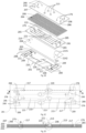
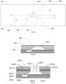
- Figs. 2A and 2B illustrate a perspective view of a bioartificial organ device 201 of a second embodiment of a device in an assembled view and in an exploded view.
- the bioartificial organ device 201 is equipped with four in-vitro barriers 202 and includes a plurality of ports 212 that will be described in more detail below.
- the bioartificial organ device 201 is composed by different body portions, including a bottom body 203 as third body portion, an actuation membrane 204, an intermediate body 205 as second body portion, a thin porous culturing membrane 206 and a top body 207 as first body portion.
- Each of the bottom body 203, intermediate body 205 and top body 207 has an essentially rectangular plate-like shape.
- Each of the actuation membrane 204 and the culturing membrane 206 has an essentially rectangular shape.
- the bottom body 203 includes two deflection actuation channels 210 and four valve actuation channels 209 in which a fluid, preferably air, is arranged to control actuation of deflection of the actuation membrane 204 and of microvalves, respectively.
- Each of the deflection actuation channels 210 connects a deflection inlet 211 with two actuation chambers 220 each having a limitation cavity and each of the valve actuation channels 209 connects a valve inlet 208 with two microvalve chambers 217.
- the actuation membrane 204 is configured to be mounted or sandwiched between the bottom body 203 and the intermediate body 205. It contains a plurality of through-holes 214, this is two groups of three through-holes each group being arranged at a longitudinal end of the actuation membrane 204. Each group of the plurality of through holes 214 has two valve inlet holes 274 at positions corresponding to the valve inlets 208 of the bottom body 203 and one actuation inlet hole 284 at positions corresponding to the deflection inlets 211 of the bottom body 203.
- the through-holes 214 allow the fluid to access the deflection actuation channels 210 and the valve actuation channels 209 located in the bottom body 203.
- the intermediate body 205 includes four perfusion channels 215 extending longitudinally along the intermediate body 205. Further, the intermediate body 205 is equipped with valve inlet through-holes 265 at positions corresponding to the valve inlets 208 of the bottom body 203 and with actuation inlet holes 265 at positions corresponding to the deflection inlets 211 of the bottom body 203. Each of the perfusion channels 215 connects a perfusion inlet 275with a culturing chamber 221 and a perfusion outlet 285. Each of the four culturing chambers 221 is provided as a conical through-hole in the intermediate body 205 widening into the direction of the actuation membrane 204.
- the culturing membrane 206 is configured to be mounted or sandwiched between the intermediate body 205 and the top body 207. It contains a plurality of through-holes 264 at positions corresponding to the valve inlets 208 of the bottom body 203, at positions corresponding to the deflection inlets 211 of the bottom body 203, at positions corresponding to the perfusion inlets 275 of the intermediate body 205 and at positions corresponding to the perfusion outlets 285 of the intermediate body 205.
- the top body 207 comprises four access chambers 213 each formed by a through-hole.
- the access chambers 213 are located in correspondence with the location of the culturing chambers 221 of the intermediate body 205.
- the top body further includes a plurality of port through-holes 216 comprising perfusion inlet holes 266 at positions corresponding to the valve inlets 208 of the bottom body 203, perfusion outlet holes 276 at positions corresponding to the deflection inlets 211 of the bottom body 203, valve inlet holes 286 at positions corresponding to the valve inlets 208 of the bottom body 203 and actuation inlet holes 296 at positions corresponding to the deflection inlets 211 of the bottom body 203.
- the top body is equipped with four in-vitro barrier access through-holes 213 as access chambers for accessing the in-vitro barriers or culturing membrane 206.
- the bottom body 203 may be made of a non-flexible material, although it is contemplated that it can be alternatively made of a flexible material.
- the bottom body 203, the intermediate body 205 and the top body 207 are preferably made of an essentially non-flexible biocompatible polymer, including but not limited to cyclic olefin copolymer, polystyrene or any other elastomeric or thermoplastic material or other materials like glass, silicon, soft or hard plastic, and the like. However, they can be made of soft material as well, and can be different from each other. It is contemplated that the thin porous culturing membrane 206 can be made of a material that is different from the material of the bodies 203, 205, 207.
- the culturing membrane 206 is preferably made of an essentially flexible material, such as polydimethylsiloxane, or any other flexible or non-flexible material, such as polyimide, parylene, or the like.
- the actuation membrane 204 is preferably made of an essentially flexible material such as silicone rubber, preferably polydimethylsiloxane, or polyimide, parylene or any other flexible material.
- valve actuation channels 209 and the deflection actuation channels 210 of the bottom body 203 are filled with a fluid, preferably air, to control deflection of the actuation membrane 204 and of the closing microvalves.
- the fluid is provided to the valve actuation channels 209 via valve ports formed by the valve inlet holes 286 of the top body 207, the corresponding through-holes 264 of the culturing membrane 206, the valve inlet holes 265 of the intermediate body 205, the valve inlet holes 274 of the actuation membrane 204 and the valve inlets 208 of the bottom body 203.
- the fluid is provided to the deflection actuation channels 210 via deflection ports formed by the actuation inlet holes 296 of the top body 207, the corresponding through-holes 264 of the culturing membrane 206, the actuation inlet holes 295 of the intermediate body 205, the actuation inlet holes 284 of the actuation membrane 204 and the deflection inlets 211 of the bottom body 203.
- the perfusion channels 215 of the intermediate body 205 are filled with a comparably incompressible fluid such as water or a water based solution.
- a comparably incompressible fluid such as water or a water based solution.
- the comparably incompressible fluid is provided into the perfusion channels 215 via perfusion inlet ports formed by the perfusion inlet holes 266 of the top body 207, the corresponding through-holes 264 of the culturing membrane 206 and the perfusion inlets 275 of the intermediate body 205 and out of the perfusion channels 215 via perfusion outlet ports formed by the perfusion outlet holes 276 of the top body 207, the corresponding through-holes 264 of the culturing membrane 206 and the perfusion outlets 285 of the intermediate body 205.
- Fig. 2C shows a top view of the bioartificial organ device 201 wherein some elements of the bioartificial organ device 201 which are not visible on the surface are indicated with dotted lines. Thereby, it is illustrated that the sections of the culturing membrane 206 which are accessible via the access chambers 213 form the four in-vitro barriers 202. As can be seen in the cross sectional view of Fig. 2D , at each of the in-vitro barriers 202 the culturing membrane 206 separates the conical culturing chamber 221 of the intermediate body 205 from the access chamber 213 of the top body 207.
- the culturing chamber 221 is connected to the left-sided perfusion inlet 275 and to the right-sided perfusion outlet 285 by the perfusion channel 215. Further, close to each of the in-vitro barriers 202 an actuation valve 219 comprising one of the actuation chambers 220 of the bottom body 203 and its adjacent section of the actuation membrane 204 is arranged.
- each of the microvalve chambers 217 of the intermediate body 205 is separated from one of the valve actuation channels 209 of the bottom body 203 by the actuation membrane 204.
- each of the microvalve chambers 217 together with its adjacent section of the actuation membrane 204 and valve actuation channel 209 forms a microvalve.
- the bioartificial organ device 201 is flipped again in its original position and the cells, for instance again epithelial, endothelial, fibroblasts, macrophages, dendritic cells, mesenchymal stem cells, or any other cells, are introduced on the in-vitro barriers 202 via the access chambers 213.
- the cell culturing membrane 206 or the in-vitro barrier 202, respectively can be mechanically stretched by applying a cyclic pressure at the deflection inlet 211 via the deflection port.
- the three-dimensional design of the microvalve shown in detail above allows for limiting the volume of media being pushed through the perfusion channel 215 into the direction of the culturing membrane 206.
- the culturing membrane 206 can be precisely deflected to a predefined extent and in a predefined manner. It is one of the aims of the microvalve to level the culturing membrane 206 at any desired strain condition and at any desired time point. This allows predefining the deflection of the culturing membrane 206 and precisely controlling the desired predefined strain of the culturing membrane 206.
- the levelling of the culturing membrane 206 can be performed at regular or irregular time intervals either to reset the predefined level of strain or define a new strain level.
- the levelling of the culturing membrane 206 might for instance be necessary in the case of small leakages, or evaporation through the culturing membrane 206 and/or through an in-vitro barrier. This may for example take place when pores of the culturing membrane 206 are comparably large and/or if the integrity of the in-vitro barrier is damaged following a mechanical, chemical or biophysical stress or a combination thereof.
- the need of a levelling of the culturing membrane may also take place if a portion of or all the culturing medium is partly or totally sampled for further analysis.
- One or several passive or one or several active microvalves or a combination thereof can be used to level the culturing membrane 206 at any predefined strain condition.
- Active microvalves can either be normally closed or normally open valves.
- the levelling of the culturing membrane 206 at a predefined strain level can easily be performed by creating a hydrostatic pressure difference between the perfusion inlet 275 and/or perfusion outlet 285 and/or the access chamber 213 by adding or removing cell culture medium or similar solution for cell culture.
- the predefined strain can also be created by applying a positive or a negative pressure either at the perfusion inlet 275 and/or perfusion outlet 285 and/or at the access chamber 213 or a combination thereof.
- the predefined strain can also be defined by varying the pressure in one or several actuation chambers. Further the levelling can be achieved by pumping cell culture medium or any fluid in or out of the culturing chamber 221, e.g. using an integrated pumping system as shown below.
- the predefined level of strain of the culturing membrane 206 is close to zero and is achieved by a combination of hydrostatic pressure difference between the perfusion inlet 275, the perfusion outlet 285 and the access chamber 213, the residual stresses of the actuation membrane 204 and of the culturing membrane 206, and the closing of the normally closed microvalve or a combination thereof.
- a normally closed microvalve a normally open microvalve could also be used.
- Fig. 2K a variation of a microvalve as alternative to the microvalve hereinbefore is shown which can be embodied in the same bioartificial organ device 201 shown hereinbefore.
- the microvalve of Fig. 2K has an asymmetric microvalve chamber 217i.
- the microvalve chamber 217i has in the top view of Fig. 2K the shape of a drop wherein the thin end of the drop passes over into the perfusion channel 215 and to the wide end of the drop the perfusion inlet 275 is connected.
- Fig. 2L shows the microvalve with the asymmetric microvalve chamber 217i during pumping of a medium.
- the actuation membrane 204 is not actuated and the perfusion channel 215 is in a completely open position.
- the actuation membrane 204 is partly actuated and the medium is forwarded into the perfusion channel 215 as well as into the direction of the perfusion inlet 275.
- the actuation membrane 204 is further actuated and connection to the perfusion inlet 275 is closed.
- the actuation membrane 204 is increasingly actuated and the medium is forwarded into the perfusion channel 215 only. No pumping into the direction of the perfusion inlet is performed.
- the actuation membrane 204 is completely actuated and final pumping of medium into the perfusion channel 215 is effected.
- a flow of the solution or medium contained in the microvalve chamber 217i is forced in or out of the culturing chamber 221 via the perfusion channel 215 and in or out of the perfusion inlet 275.
- the flow that is forced in or out of the culturing chamber 221 should be minimized in order not to affect the predefined strain of the culturing membrane 206.
- One possible design of the microvalve to fulfil this objective is the minimization of the size of the microvalve cavity, to minimize the volume displaced when the microvalve closes or opens.
- a drawback of this solution can be the comparably high pressure required to actuate the comparably small membrane 204 and the related problems, such as the sticking of the actuation membrane 204 against the microvalve chamber 217i due to the high pressure that may need special anti-adhesion coatings.
- microvalve chamber 217i Another possibility is to design the microvalve chamber 217i so that the bidirectional flow generated by the closing of the microvalve 3002 is asymmetric, and preferably flows into the direction of the perfusion inlet 275 rather than in the perfusion channel 215 and the culturing chamber 221. This can be achieved by first closing the perfusion inlet from the microvalve chamber 217 while keeping the outlet to the perfusion channel 215 open. This is for instance performed using a three-dimensional geometry of the microvalve chamber 217i as explained. The three-dimensional valve has a diameter in the millimetre range that enables a rapid deflection of the actuation membrane 204.
- the actuation membrane 204 meets the intermediate body 205, which has a lower protrusion, corresponding to the inlet of the perfusion channel 215. This immediately blocks the flow in direction of the culturing membrane 206. While the pressure in the actuation channel 209 continues to rise, the actuation membrane 204 is further deflected.
- the advantage of this system is that it does not need a large pressure, as the dimensions of the microvalve can be in the millimetre size. In addition, a tight closing of the perfusion channel can be guaranteed.
- Such three-dimensional microvalves can easily be produced by using 3D printing technologies as well as stereolithography, photolithography, standard milling, lamination, injection molding, hot embossing or a combination thereof.
- an asymmetric valve to perform the levelling of the culturing membrane 206, in order to limit the flow pushed in the perfusion channel in the direction of the culturing membrane.
- the asymmetric valve in another embodiment, it is envisaged to use the asymmetric valve as pump.
- the asymmetric microvalve In sharp contrast to existing peristaltic pumps, which most use three valve cavities to pump fluid, the asymmetric microvalve only needs one cavity to pump fluid. This represents a great simplification and advantage, as the set-up would be simplified with one actuation channel per pump.
- the flow rate of the pumped fluid can be regulated by the geometry respectively the size of the pump cavity, the applied actuation frequency as well as the applied force magnitude to deflect the membrane.
- the membrane can be deflected, using different actuation principles e.g. magnetic, pneumatic (preferred), electric or using a shape memory alloy.
- the pump could be used to transport cell culture medium, growth factors, drugs, xenobiotics or other substances in the culturing chamber. It is also envisaged to create a recirculating perfusion system.
- the asymmetric valve is made of a microvalve cavity that contains an inclined wall, on which the actuation membrane is deflected upon. A small inlet of the perfusion channel is created in the inclined wall to limit the flow induced by the actuation of the microvalve to be pushed or drawn in or out of the culturing chamber 221.
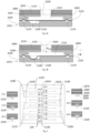
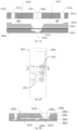
- Figs. 3A and 3B show views of a bioartificial organ device 2010 of a third embodiment of a device.
- the bioartificial organ device 2010 is essentially identically embodied as the bioartificial organ device 201 described above.
- the bioartificial organ device 2010 comprises a bottom body 2030 as a third body portion with deflection actuation channels 2100, valve actuation channels, microvalve chambers 2170 and actuation chambers 2200 having limitation cavities.
- On top of the bottom body 2030 an intermediate body 2050 with perfusion channels 2150 and culturing chambers 2210 is arranged as second body portion wherein between the bottom body 2030 and the intermediate body 2050 an actuation membrane 2040 is sandwiched.
- a top body 2070 with access chambers 2130 is arranged as first body portion, wherein between the intermediate body 2050 and the top body 2070 a thin porous culturing membrane 2060 is sandwiched. Sections of the culturing membrane 2060 being located in or below the access chambers 2130 of the top body 2070 form in-vitro barriers 2020.
- Fig. 3A illustrates schematically the mechanism responsible of the mechanical stretching of the in-vitro barrier 2020.
- a negative pressure in the actuation chambers 2200 then negatively or downwardly deflects the actuation membranes 2040 into the limitation cavity of the actuation chamber 2200, which induces positive deflection of the in-vitro barrier 2020 in a z- or downward direction.
- the volume of the limitation cavity is identical to the displaced volume of the in-vitro barrier 2020, so that the maximum deflection w max of the in-vitro barrier 2020 is limited by the limitation cavity.
- the stress in the in-vitro barrier 2020 is thus very well controlled and kept constant, regardless of the mechanical properties of the actuation membrane 2040 and of the culturing membrane 2060.
- actuated microvalves can either be designed in a normally closed or a normally open mode. It is also contemplated to use the bioartificial organ device 2010 without microvalves, by slightly increasing the volume of the actuation chamber 2200 in order to compensate the volume of the fluid transported in the perfusion channels 2150 at each actuation cycle.
- Fig. 4 shows a bioartificial organ device 2019 of a fourth embodiment of a device.
- the bioartificial organ device 2019 is principally similarly arranged as the bioartificial organ device 201 and the bioartificial organ device 2010 described above. It comprises a bottom body 2039 as a third body portion with five pairs of deflection actuation channels 2109 connected to five deflection inlets 2189 on one side and to ten actuation chambers 229 on the opposite side.
- an intermediate body 2059 with twelve perfusion channels 2159 connected to twelve perfusion inlets 2189, twelve culturing chambers and twelve perfusion outlets 2179 are arranged as second body portion wherein between the bottom body 2039 and the intermediate body 2059 an actuation membrane 2049 is sandwiched.
- a top body 2079 with twelve access chambers 2139 is arranged as first body portion, wherein between the intermediate body 2059 and the top body 2079 a thin porous culturing membrane 2069 is sandwiched. Sections of the culturing membrane 2069 being located in or below the access chambers 2139 of the top body 2079 form twelve in-vitro barriers 2029.
- Each of the ten actuation chambers 229 is associated to one of the twelve culturing chambers.
- the actuation chambers 229 have limitation cavities with varying volumes. Thereby, the volumes of the different limitation cavities 2219, 2229, 2239, 2249, 2259 of the actuation chambers 229 correspond to a specific linear strain value given in percentage of the strain taking place in the in-vitro barrier 2029. Shown in cross sectional view along lines A-A are limitation cavities being zero and not inducing any strain (0% strain).
- the two actuation chambers 229 shown in cross sectional view along lines B-B have limitation cavities 2219 generating 5% strain.
- the two actuation chambers 229 shown in cross sectional view along lines C-C have limitation cavities 2229 generating 10% strain.
- the two actuation chambers 229 shown in cross sectional view along lines D-D have limitation cavities 2239 generating 15% strain.
- the two actuation chambers 229 shown in cross sectional view along lines E-E have limitation cavities 2249 generating 20% strain.
- the two actuation chambers 229 shown in cross sectional view along lines F-F have limitation cavities 2259 generating 25% strain.
- this possible embodiment of the bioartificial organ device 2019 allows different linear strains of the in-vitro barriers 2029 on a single bioartificial organ device 2019. It is to note that any values contained within the strains given above can be realized. The preferred strain being 10%, but can be comprised between 0 and 30%. Positive strains are also possible as described in more detail below.
- Fig. 5A shows a bioartificial organ device 2018 of a fifth embodiment of a device.
- the bioartificial organ device 2018 is principally similarly arranged as the bioartificial organ device 201, the bioartificial organ device 2010 and the bioartificial organ device 2019 described above. It comprises a bottom body 2038 as a third body portion with deflection actuation channels connected to deflection inlets on one side and to actuation chambers 2208 on the opposite side.
- an intermediate body 2058 with perfusion channels 2158 connected to perfusion inlets 21518, culturing chambers 2218 and perfusion outlets 21528 is arranged as second body portion wherein between the bottom body 2038 and the intermediate body 2058 an actuation membrane 2048 is sandwiched.
- a top body 2078 with perfusion inlet holes 21618, access chambers 2138 and perfusion outlet holes 21628 is arranged as first body portion, wherein between the intermediate body 2058 and the top body 2078 a thin porous culturing membrane 2068 is sandwiched. Sections of the culturing membrane 2068 being located in or below the access chambers 2138 of the top body 2078 form in-vitro barriers 2028.
- Each of the actuation chambers of the bottom body 2038 of the bioartificial organ device is equipped with two limitation cavities 2208 having a rounded bottom surface.
- the diameter of the actuation cavities 2208 can, e.g., be between 300 micrometers and 10 millimeters, and preferably 3.5 millimeters.
- the limitation cavities 2208 can, e.g., be depressurized individually, either to create 0% strain in the in-vitro barrier 2028 by not depressurizing the limitation cavities 2208, or, e.g., 5% strain in the in-vitro barrier 2028 by depressurizing one of the limitation cavities 2208 so that the actuation membrane 2048 is completely deflected in one of the limitation cavities 2208 while the other limitation cavity 2208 remains at atmospheric pressure, or 10% strain in the in-vitro barrier 2028 by depressurizing both limitation cavities 2208.
- Fig. 5B shows a bioartificial organ device 2017 of a sixth embodiment of a device.
- the bioartificial organ device 2017 is generally identical to the bioartificial organ device 2018 described above. It comprises a bottom body 2037 as a third body portion with deflection actuation channels connected to deflection inlets on one side and to actuation chambers 2207 on the opposite side.
- On top of the bottom body 2037 an intermediate body 2057 with perfusion channels 2157 connected to perfusion inlets 21517, culturing chambers 2217 and perfusion outlets 21527 are arranged as second body portion wherein between the bottom body 2037 and the intermediate body 2057 an actuation membrane 2047 is sandwiched.
- a top body 2077 with perfusion inlet holes 21617, access chambers 2137 and perfusion outlet holes 21627 is arranged as first body portion, wherein between the intermediate body 2057 and the top body 2077 a thin porous culturing membrane 2067 is sandwiched. Sections of the culturing membrane 2067 being located in or below the access chambers 2137 of the top body 2077 form in-vitro barriers 2027.
- Each of the actuation chambers of the bottom body 2037 of the bioartificial organ device is equipped with three limitation cavities 2207 having a rounded bottom surface.
- the diameter of the actuation cavities 2207 can, e.g., be between 300 micrometers and 10 millimeters, and preferably 3.5 millimeters.
- the limitation cavities 2207 can, e.g., be depressurized individually, either to create 0% strain in the in-vitro barrier 2027 by not depressurizing the limitation cavities 2207, or, e.g., 5% strain in the in-vitro barrier 2027 by depressurizing one of the limitation cavities 2207 so that the actuation membrane 2047 is completely deflected in one of the limitation cavities 2207 while the other limitation cavities 2207 remain at atmospheric pressure, or 10% strain in the in-vitro barrier 2027 by depressurizing two limitation cavities 2207 so that the actuation membrane 2047 is completely deflected in two of the limitation cavities 2207 while the other limitation cavity 2207 remains at atmospheric pressure, or 15% strain in the in-vitro barrier 2027 by depressurizing all three limitation cavities 2207.
- the number of limitation cavities can be increased such that the volume of the actuation cavities can be designed and fabricated so that specific values of strains can be induced in the respective in-vitro barrier.
- the shape of the limitation cavities can be half-spherical with a vertical half-radius preferably being between 100 micrometers and 5 millimeters, with a preferred depth of about 549 micrometers for about 5% strain, about 668 micrometers for about 10% strain, about 753 micrometers for about 15% strain, about 823 micrometers for about 20% strain, about 884 micrometers for about 25% strain and about 939 micrometers for about 30% strain.
- the limitation cavities can be rectangular. It is contemplated that the actuation cavity can also take other shapes, such as half-circular shapes, ellipsoidal shape, quadratic shape or triangular shape.
- a diameter of the in-vitro barriers of all embodiments of bioartificial organ devices described herein can be in a range of about 100 micrometers to about 10 millimeters, and is preferably comprised between 1 and 5 millimeters.
- the in-vitro barriers have circular diameters, but it is contemplated that they can have elliptical, quadratic or rectangular surfaces, or the like.
- a bioartificial organ device 2016 of a seventh embodiment of a device is shown.
- the bioartificial organ device 2016 is principally similarly arranged as the bioartificial organ devices 201 2010, 2019, 2018, 2017 described above. It comprises a bottom body 2036 as a third body portion with microvalves having microvalve chambers 2176 as well as with deflection actuation channels connected to deflection inlets on one side and to actuation chambers 2206 on the opposite side.
- an intermediate body 2056 with perfusion channels 2156 connected to perfusion inlets, culturing chambers 2216 and perfusion outlets is arranged as second body portion wherein between the bottom body 2036 and the intermediate body 2056 an actuation membrane 2046 is sandwiched.
- a top body 2076 with perfusion inlet holes, access chambers 2136 and perfusion outlet holes is arranged as first body portion, wherein between the intermediate body 2056 and the top body 2076 a thin porous culturing membrane 2066 is sandwiched. Sections of the culturing membrane 2066 being located in or below the access chambers 2136 of the top body 2076 form in-vitro barriers 2026.
- Each culturing chamber 2216 is associated to three access chambers 2136 and, thus, to three in-vitro barriers 2026.
- each actuation chamber 2206 is associated to one culturing chamber 2216.
- the aim of having plural in-vitro barriers 2026 per culturing chamber 2216 in the bioartificial organ device 2016 is to increase the overall surface of the in-vitro barrier 2026.
- a group of in-vitro barriers 2026 is stretched simultaneously using a single actuation valve with an actuation chamber 2206.
- the pressure is distributed homogeneously in the cell culturing chamber 2216 allowing the in-vitro barriers 2026 to deflect simultaneously, with the microvalves having the valve chambers 217 keeping the culturing chamber 2216 closed.
- Fig. 6B shows a bioartificial organ device 2015 of an eight embodiment of a device.
- the bioartificial organ device 2015 is principally similarly arranged as the bioartificial organ devices 201 2010, 2019, 2018, 2017, 2016 described above. It comprises a bottom body 2035 as a third body portion with microvalves having microvalve chambers 2175 as well as with deflection actuation channels connected to deflection inlets on one side and to actuation chambers 2205 on the opposite side.
- On top of the bottom body 2035 an intermediate body 2055 with perfusion channels 2155 each being connected to perfusion inlets, three culturing chambers 2215 and perfusion outlets is arranged as second body portion wherein between the bottom body 2035 and the intermediate body 2055 an actuation membrane 2045 is sandwiched.
- a top body 2075 with perfusion inlet holes, access chambers 2135 and perfusion outlet holes is arranged as first body portion, wherein between the intermediate body 2055 and the top body 2075 a thin porous culturing membrane 2065 is sandwiched. Sections of the culturing membrane 2065 being located in or below the access chambers 2135 of the top body 2075 form in-vitro barriers 2025.
- Each perfusion culturing chamber 2215 is associated to one actuation chamber 2045 and to one valve chamber 2175.
- the bioartificial organ device 2015 is equipped with groups of three in-vitro barriers 2025 that are actuated individually, each with a dedicated actuation valve or actuation chamber 2205, respectively.
- the microvalve chambers 217 are located between the in-vitro barriers 2025 of a group so that each cell culturing chamber 2215 can be individually closed.
- Figs. 7A, 7B, 7C show a bioartificial organ device 2014 of a ninth embodiment of a device.
- the bioartificial organ device 2014 is principally similarly arranged as the bioartificial organ devices 201 2010, 2019, 2018, 2017, 2016, 2015 described above.
- the bioartificial organ device 2014 comprises a bottom body 2034 as fourth body portion on top of which an intermediate body 2054 is arranged.
- the intermediate body 2054 has a second body portion of the bioartificial organ device 2014 with perfusion channels 2154 each connecting a perfusion inlet 2184 with a culturing chamber 2214 and a perfusion outlet 2194.
- the intermediate body 2054 further has a third body portion of the bioartificial organ device 2014 comprising end portions of deflection channels 2104 each passing over into a actuation chamber 2204 with a limitation cavity.
- the actuation chamber 2204 of the third body portion is located adjacent to the perfusion channel 2154 of the second body portion between the perfusion inlet 2184 and the culturing chamber 2214.
- the actuation chamber 2204 is separated from the perfusion channel 2154 by an actuation membrane 2044.
- a top body 2074 with perfusion inlet holes 2084, access chambers 2134, sections of the deflection channels 2104 and perfusion outlet holes is arranged as first body portion, wherein between the intermediate body 2054 and the top body 2074 a thin porous culturing membrane 2064 is sandwiched. Sections of the culturing membrane 2064 being located in or below the access chambers 2134 of the top body 2074 form in-vitro barriers 2024.
- the actuation chamber 2204 is arranged in the third body portion located in the intermediate body 2054.
- the actuation membrane 2044 is deflected via the deflection channel 2104.
- the actuation membrane 2044 can be upwardly or negatively deflected by a negative pressure in the deflection channel 2104. This causes the respective in-vitro barrier 2024 to deflect downwardly or into the culturing chamber 2214.
- a positive pressure in the deflection channel 2104 by applying a positive pressure in the deflection channel 2104 the actuation membrane 2044 can be downwardly or positively deflected. This causes the respective in-vitro barrier 2024 to be deflected upwardly or into the access chamber 2134.
- the in-vitro barrier 2024 can thus be efficiently strained positively, negatively or both positively and negatively.
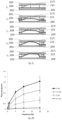
- a fabrication of a thin porous culturing membrane 206x as it can be implemented in any of the embodiments of bioartificial organ devices described above is shown.
- the culturing membrane 206x can be made of a material with a plurality of pores 801 whereby molecules, cells, fluid or any other media is capable of passing though the thin porous culturing membrane 206x via one or more pores 801.
- the thin porous culturing membrane 206x is made of a material that allows undergoing stress and/or strain in response to pressure differentials present between the cell culturing chamber and the pressure surrounding the bioartificial organ device.
- the thickness of the thin porous culturing membrane 206x is between about 20 nanometers and about 20 micrometers, preferably between about 200 nanometers and about 5 micrometers.
- the size of the pores 801 is between about 0.4 micrometers and about 12 micrometers, preferably at about 3 micrometers.
- the density of the pores is between about 10'000 and about 100'000'000 pores/cm 2 , preferably at about 800'000 pores/cm 2 . It is also contemplated that the in-vitro barrier can be equipped with a non-porous membrane.
- FIGs. 8A , 8B and 8C show the schematic fabrication process of the thin porous culturing membrane 206x with possible geometries of the membrane holes 801.
- a mold 802 with an array of micropillars 803 is covered by a covering substrate 804.
- a non-polymerized fluid 805 is passively introduced by capillary forces or pressed by force in the empty space created between the mold 802, the covering substrate 804 and the array of micropillars 803 (see Fig. 8B).
- Figure 8C illustrates the cross-section of the assembly of the mold 802 and the covering substrate 804 with the spaces filled with the non-polymerized fluid 805.
- the height of the micropillars 803 defines the thickness of the non-polymerized fluid 805.
- the mold 802 can be fabricated by wet or dry etching of silicon, silicon dioxide, silicon nitride or the like.
- Figs. 9A and 9B show a bioartificial organ device 901 of a tenth embodiment of a device in a top view and a cross sectional view.
- the in-vitro barrier 9202 can be perfused on both sides.
- a perfusion channel 904 is connected to the top side of the in-vitro-barrier 9202 via the in-vitro barrier access ports and one perfusion channel 902 to its bottom side.
- Figure 9B illustrates a detailed view of the cross-section of the bioartificial organ device 901 in this possible embodiment. It is contemplated that several perfusion channels 904 are connected to the in-vitro barrier 9202.
- top bodies 2073 each with an access chamber 2133 is arranged as first body portion, wherein between the intermediate body 2053 and the top bodies 2073 as well as between the top bodies 2073 thin porous or non-porous culturing membranes 2063 are sandwiched. Sections of the culturing membranes 2063 being located in or below the access chambers 2133 of the top body 2073 form in-vitro barriers 2023.
- Each of the top body 2073 between the intermediate body 2053 and the next top body 2073 as well as the top body 2073 between the two other top bodies 2073 is equipped with a access chamber inlet channel 20713 and a access chamber outlet channel 20723 for providing a medium to and from the respective access chamber 2133.
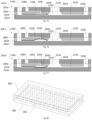
- Figs. 11A, 11B, 11C and 11D show a bioartificial organ device 2012 of a twelfth embodiment of a device.
- the bioartificial organ device 2012 is principally similarly arranged as the bioartificial organ devices 201, 901, 2010, 2019, 2018, 2017, 2016, 2015, 2014, 2013 described above. It comprises a bottom body 2032 as a third body portion with microvalves having microvalve chambers 2172 as well as with deflection actuation channels 2102 connected to deflection inlets on one side and to actuation chambers 2202 on the opposite side.
- an actuation membrane 2042 covering the bottom body 2032 is mounted.
- the bioartificial organ device 2012 further comprises an intermediate body 2052 with perfusion channels 2152 connected to perfusion inlets 21512, culturing chambers 2212 and perfusion outlets 21522 as second body portion.
- a top body 2072 with perfusion inlet holes, access chambers 2132 and perfusion outlet holes is arranged as first body portion, wherein between the intermediate body 2052 and the top body 2072 a thin porous culturing membrane 2062 is sandwiched. Sections of the culturing membrane 2062 being located in or below the access chambers 2132 of the top body 2072 form in-vitro barriers 2022.
- the bioartificial organ device 2012 is adapted such that the bottom body 2032 and the actuation membrane 2042 can be removed as bottom part from the intermediate body 2052, the culturing membrane 2062 and the top body 2072 as a top part.
- the intermediate body 2052, the culturing membrane 2062 and the top body 2072 are flipped by 180° and a culturing medium 7022 is dropped in the culturing chamber 2212.
- the culturing medium 7022 containing cells and/or other cellular aggregates in suspension is loaded on the backside of the culturing membrane 2062 and cells 7012 grow and form an in-vitro barrier 2022.
- the cells 7012 are loaded on the backside of the culturing membrane 2062 with the bioartificial organ device 2012 turned upside down.
- Fig. 11B the intermediate body 2052, the culturing membrane 2062 and the top body 2072 are flipped by 180° and a culturing medium 7022 is dropped in the culturing chamber 2212.
- the culturing medium 7022 containing cells and/or other cellular aggregates in suspension is loaded on the backside of the culturing membrane 2062 and cells 7012 grow and form an in-vitro barrier 2022.
- the cells 7012 are loaded on
- the intermediate body 2052, the culturing membrane 2062 and the top body 2072 is turned down and assembled with the bottom body 2032 and the actuation membrane 2042. Both parts can be assembled using a holder using mechanic, electric, magnetic forces or a combination thereof.
- the culturing medium 7022 is then squeezed between the two bodies and guided via the perfusion channels 2152.
- additional cells 7042 provided in a culturing medium 7032 can be loaded and cultured on the upper side of the culturing membrane 2062 inside the access chamber 2132. As described earlier, the microvalves are closed prior to activating the actuation of the culturing membrane 2062.
- the fluid is trapped between the body parts and in the culturing chamber 2132 that has a volume that is large enough for the cell to survive for at least the period of the assay.
- the volume of the culturing chamber 2212 is about 50 microliters, but can be comprised between about 0.5 microliters and about 500 microliters.
- the excess of fluid is directed towards a fluid excel chamber in which it overflows. It is contemplated that the bioartificial organ device 2012 can be opened and closed again to repeat the process described above, in order to load additional cell type, molecules, nanoparticles.
- a bioartificial organ device 4000 of a thirteenth embodiment of a device is shown.
- the bioartificial organ device 4000 is principally similarly arranged as the bioartificial organ devices 201, 901, 2010, 2019, 2018, 2017, 2016, 2015, 2014, 2013, 2012, 2011 described above.
- It comprises a bottom body 2031i as a third body portion with deflection actuation channels connected to deflection inlets on one side and to actuation chambers 2201i on the opposite side.
- an intermediate body 2051i with perfusion channels 2151i connected culturing chambers 2211i is arranged as second body portion wherein between the bottom body 2031i and the intermediate body 2051i an actuation membrane 2041i is sandwiched.
- a top body 2071i with access chambers 2131i is arranged as first body portion, wherein between the intermediate body 2051i and the top body 2071i a thin porous culturing membrane 2061i is sandwiched. Sections of the culturing membrane 2061i being located in or below the access chambers 2131i of the top body 2071i form in-vitro barriers 2021i.
- the perfusion channels 2151i are cavities in the intermediate body 2051i that are closed once the top body 2071i is assembled with the intermediate body 2051i.
- the assembly between the top body 2071i on which the culturing membrane 2061i is attached is reversible. It can be used to load one or several drops of cell culture medium with suspended cells, prior to be assembled.
- bioartificial organ device can be reversibly bonding for the same or other purposes. It is envisaged that the top body part may be reversibly assembled with the intermediate body part.
- the reversible bonding system also allows to create microvalves using body parts that can reversibly being assembled, cleaned, surface treated to render them hydrophilic and hydrophobic.
- a drop of culturing medium with suspended cells is placed on top of the bottom body 2032i.
- the top body is then immediately bonded to the lower body with methods explained earlier and flipped by 180° to allow the cells to adhere on the culturing membrane 2062i. Once the cells are adherent the bioartificial organ device is flipped again and cells cultured at the top of the culturing membrane.
- a drop of culturing medium without suspended cells is placed on top of the bottom body 2032i.
- the top body is then immediately bonded on the lower body with methods explained earlier and cells added at the top of the culturing membrane.
- Such embodiment would be interesting to study cells only on the top of the culturing membrane 2062i.
- a bioartificial organ device 2011 of a fourteenth embodiment of a device is shown.
- the bioartificial organ device 2011 is principally similarly arranged as the bioartificial organ devices 201, 901, 2010, 2019, 2018, 2017, 2016, 2015, 2014, 2013, 2012 described above.
- It comprises a bottom body 2031 as a third body portion with deflection actuation channels connected to deflection inlets on one side and to actuation chambers 2201 on the opposite side.
- an intermediate body 2051 with perfusion channels 2151 connected culturing chambers 2211 is arranged as second body portion wherein between the bottom body 2031 and the intermediate body 2051 an actuation membrane 2041 is sandwiched.
- a top body 2071 with access chambers 2131 is arranged as first body portion, wherein between the intermediate body 2051 and the top body 2071 a thin porous culturing membrane 2061 is sandwiched. Sections of the culturing membrane 2061 being located in or below the access chambers 2131 of the top body 2071 form in-vitro barriers 2021.
- the bioartificial organ device 2011 is equipped with means for closing the culturing chamber 2211. As shown in Fig. 12 , the culturing chamber 2211 is closed once cells are seeded on the bottom side of the culturing membrane 2061.
- a bioartificial organ device 4001 of a fifteenth embodiment of a device is shown.
- the bioartificial organ device 4001 is principally similarly arranged as the bioartificial organ devices 201, 901, 2010, 2019, 2018, 2017, 2016, 2015, 2014, 2013, 2012, 2011 described above. It comprises a bottom body 2031ii as a third body portion with deflection actuation channels connected to deflection inlets on one side and to actuation chambers 2201ii on the opposite side.
- an intermediate body 2051ii with perfusion channels 2151ii connected culturing chambers 2211ii is arranged as second body portion wherein between the bottom body 2031ii and the intermediate body 2051ii an actuation membrane 2041ii is sandwiched.
- a top body 2071ii with access chambers 2131ii is arranged as first body portion, wherein between the intermediate body 2051ii and the top body 2071ii a thin porous culturing membrane 2061ii is sandwiched. Sections of the culturing membrane 2061ii being located in or below the access chambers 2131ii of the top body 2071ii form in-vitro barriers 2021ii.
- the bioartificial organ device 4001 is equipped with a normally closed microvalve 3002ii for closing the culturing chamber 2211ii.
- This microvalve 3002ii allows to calibrate the thin porous membrane 2021ii, by equilibrating the pressures on both sides of the thin porous membrane 2021ii. Indeed, after closing the culturing chamber 2211ii, the thin porous membrane 2021ii may slightly be inflated due to the excess of culturing medium contained in the hanging drop.
- the actuation membrane 2041ii Prior to the closing of the culturing chamber 2211ii, the actuation membrane 2041ii is deflected by applying a negative pressure in the actuation channel 3001ii.
- the negative pressure is shut off in the actuation channel 3001ii that releases the actuation membrane 2041ii and closes the microvalve 3002ii.
- the design of the microvalve 3002ii is conceived so that a minimum of the culturing medium enters in the perfusion channel 2151ii and the culturing chamber when the microvalve 3002ii closes.
- Fig. 14 illustrates the effects of a physiologic (10% linear), cyclic mechanical strain on the permeability of an epithelial barrier.
- Lung bronchial epithelial cells (16HBEo-) were seeded at a density of 250'000 cells/cm 2 onto the fibronectin-coated culturing membrane. The cells were allowed to adhere and to grow for 72h. The cells were exposed to cyclic strain (10% linear, 0.2Hz) for 19h, whereas the control was kept at static conditions. Cell permeability was measured using two molecules, FITC-sodium and RITC-Dextran.
- Fig. 15 illustrates the effects of a physiologic, cyclic mechanical strain on the metabolic activity of a confluent layer of primary human alveolar epithelial cells.
- primary human alveolar epithelial cells were seeded at a density of 400,000 cells/cm 2 onto the gelatin/collagen1-coated actuation membrane. The cells were allowed to adhere and to grow for 48h. The cells were exposed to cyclic strain (10% linear, 0.2Hz) for 48h, whereas the control was kept at static conditions for the same period of time. Cell vitality and proliferation were measured using the non-toxic AlamarBlue assay (Invitrogen) 1h before applying the cyclic stretch and 23h and 47h after starting to stretch the cells.
- Microfluidic systems are in general well suited for such implementation.
- one of the challenges of an in-vitro barrier systems like the one described is the culture of the cells at the bottom of the culturing membrane. This requires flipping the platform in order to allow the cells to adhere on the membrane (otherwise they would sediment at the bottom of the system).
- this solution presents the important advantage that the number of cells seeded on the membrane is well known. Then the system is closed (without air bubbles) and used either in a perfused or a non-perfused mode.
- the lower part can be made of a recess located around the culturing membrane that will contain the medium once assembled.
- a system allowing for the excess of solution to flow out of the culturing chamber is implemented so that no air bubbles can be contained in the system.
- Two solutions are envisaged, the first is made of a valve, the second without valve. In both cases, one needs to make sure that the culturing membrane is not deflected when the system is closed.
- the culturing chamber made of the recess closed by the body portion can have a volume of about 50 ⁇ L and can be in the range of about 10 ⁇ L to about 200 ⁇ L. In a perfused system the volume of the recess does not need to be as large and can be reduced to a few microliters.
- a holder maintains the two body parts together with a mechanical force generated by a spring, or an attachment means such as screws or the like. It could also be envisaged that the two parts would be assembled using specific pins in the top or bottom parts that would be clipped in the other part.
Landscapes
- Health & Medical Sciences (AREA)
- Life Sciences & Earth Sciences (AREA)
- Engineering & Computer Science (AREA)
- Chemical & Material Sciences (AREA)
- Zoology (AREA)
- Organic Chemistry (AREA)
- Bioinformatics & Cheminformatics (AREA)
- Wood Science & Technology (AREA)
- Genetics & Genomics (AREA)
- Biotechnology (AREA)
- Biomedical Technology (AREA)
- Biochemistry (AREA)
- Sustainable Development (AREA)
- General Engineering & Computer Science (AREA)
- General Health & Medical Sciences (AREA)
- Microbiology (AREA)
- Molecular Biology (AREA)
- Cell Biology (AREA)
- Immunology (AREA)
- Analytical Chemistry (AREA)
- Mechanical Engineering (AREA)
- General Chemical & Material Sciences (AREA)
- Physiology (AREA)
- Apparatus Associated With Microorganisms And Enzymes (AREA)
- Micro-Organisms Or Cultivation Processes Thereof (AREA)
Claims (8)
- Verfahren zum Verwenden einer Vorrichtung (100; 201; 901; 2010; 2011; 2012; 2013; 2014; 2015; 2016; 2017; 2018; 2019) für ein In-vitro-Modellieren von In-vivo-Geweben von Organen, die Vorrichtung (100; 201; 901; 2010; 2011; 2012; 2013; 2014; 2015; 2016; 2017; 2018; 2019) umfassend einen ersten Körperabschnitt (207; 2070; 2071; 2072; 2073; 2074; 2075 2076; 2077; 2078; 2079) mit mindestens einer Zugangskammer (213; 2130; 2131; 2132; 2133; 2134; 2135; 2136; 2137; 2138; 2139), einen zweiten Körperabschnitt (205; 2050; 2051; 2052; 2053; 2054; 2055; 2056; 2057; 2058; 2059) mit mindestens einer Kultivierungskammer (221; 2210; 2211; 2212; 2213; 2214; 2215; 2216; 2217; 2218; 2219) und einer Kultivierungsmembran (206; 2060; 2061; 2062; 2063; 2064; 2065; 2066; 2067; 2068; 2069), welche die mindestens eine Zugangskammer (213; 2130; 2131; 2132; 2133; 2134; 2135; 2136; 2137; 2138; 2139) von der Kultivierungskammer (221; 2210; 2211; 2212; 2213; 2214; 2215; 2216; 2217; 2218; 2219) trennt, und einen dritten Körperabschnitt (203; 2030; 2031; 2032; 2033; 2054; 2035; 2036; 2037; 2038; 2039) mit mindestens einer Betätigungskammer (220; 2200; 2201 2202; 2203; 2204; 2205; 2206; 2207; 2208; 2209) und einer Betätigungsmembran (204; 2040; 2041; 2042; 2043; 2044; 2045; 2046; 2047; 2048; 2049), welche die mindestens eine Kultivierungskammer (221; 2210; 2211; 2212; 2213; 2214; 2215; 2216; 2217; 2218; 2219) von der mindestens einen Betätigungskammer (220; 2200; 2201; 2202; 2203; 2204; 2205; 2206; 2207; 2208; 2209) trennt, das Verfahren umfassend:Umdrehen des ersten Körperabschnitts (207; 2070; 2071; 2072; 2073; 2074; 2075 2076; 2077; 2078; 2079) und des zweiten Körperabschnitts (205; 2050; 2051; 2052; 2053; 2054; 2055; 2056; 2057; 2058; 2059) zusammen mit der Kultivierungsmembran (206; 2060; 2061; 2062; 2063; 2064; 2065; 2066; 2067; 2068; 2069) um 180°; undInkubieren von Zellen durch Bereitstellen der Zellen auf einer ersten Seite der Kultivierungsmembran (206; 2060; 2061; 2062; 2063; 2064; 2065; 2066; 2067; 2068; 2069), bis die Zellen an der Kultivierungsmembran (206; 2060; 2061; 2062; 2063; 2064; 2065; 2066; 2067; 2068; 2069) anhaften;Herumdrehen des ersten Körperabschnitts (207; 2070; 2071; 2072; 2073; 2074; 2075 2076; 2077; 2078; 2079) und des zweiten Körperabschnitts (205; 2050; 2051; 2052; 2053; 2054; 2055; 2056; 2057; 2058; 2059) zusammen mit der Kultivierungsmembran (206;2060;2061;2062;2063;2064;2065;2066;2067;2068;2069) und Zusammensetzen des ersten Körperabschnitts (207; 2070; 2071; 2072; 2073; 2074; 2075 2076; 2077; 2078; 2079) und des zweiten Körperabschnitts (205; 2050; 2051; 2052; 2053; 2054; 2055; 2056; 2057; 2058; 2059) zusammen mit der Kultivierungsmembran (206; 2060; 2061; 2062; 2063; 2064; 2065; 2066; 2067; 2068; 2069) mit dem dritten Körperabschnitt (203; 2030; 2031; 2032; 2033; 2054; 2035; 2036; 2037; 2038; 2039) und der Betätigungsmembran (204; 2040; 2041; 2042; 2043; 2044; 2045; 2046; 2047; 2048; 2049); undInkubieren weiterer Zellen durch Bereitstellen der weiteren Zellen auf einer zweiten Seite der Kultivierungsmembran (206; 2060; 2061; 2062; 2063; 2064; 2065; 2066; 2067; 2068; 2069) im Inneren der mindestens einen Zugangskammer (213; 2130; 2131; 2132; 2133; 2134; 2135; 2136; 2137; 2138; 2139), bis die weiteren Zellen an der Kultivierungsmembran (206; 2060; 2061; 2062; 2063; 2064; 2065; 2066; 2067; 2068; 2069) anhaften.
- Verfahren nach Anspruch 1, wobei die Vorrichtung (100; 201; 901; 2010; 2011; 2012; 2013; 2014; 2015; 2016; 2017; 2018; 2019) ferner einen Perfusionskanal (215; 2150; 2151; 2152; 2153; 2154; 2155; 2156; 2157; 2158; 2159) mit einem Einlass (275; 2184; 21512; 21517; 21518; 21519), einem Auslass (285; 2194; 21522; 21527; 21528; 21529) und der mindestens einen Kultivierungskammer (221; 2210; 2211; 2212; 2213; 2214; 2215; 2216; 2217; 2218; 2219) umfasst, wobei der Einlass (275; 2184; 21512; 21517; 21518; 21519), die mindestens eine Kultivierungskammer (221; 2210; 2211; 2212; 2213; 2214; 2215; 2216; 2217; 2218; 2219) und der Auslass (285; 2194; 21522; 21527; 21528; 21529) verbunden sind.
- Verfahren nach Anspruch 1 oder 2, wobei das Inkubieren der weiteren Zellen auf der zweiten Seite der Kultivierungsmembran (206; 2060; 2061; 2062; 2063; 2064; 2065; 2066; 2067; 2068; 2069) umfasst, dass mindestens eines von Wachstumsfaktoren, Chemikalien, Gasen, Nährstoffen, Medikamenten, Xenobiotika, Blut oder Blutserum zusammen mit den weiteren Zellen in die Zugangskammer (213; 2130; 2131; 2132; 2133; 2134; 2135; 2136; 2137; 2138; 2139) bereitgestellt wird.
- Verfahren nach einem der Ansprüche 1 bis 3, wobei das Verfahren ein Betätigen der Kultivierungsmembran (206; 2060; 2061; 2062; 2063; 2064; 2065; 2066; 2067; 2068; 2069) durch Bewegen der Betätigungsmembran (204; 2040; 2041; 2042; 2043; 2044; 2045; 2046; 2047; 2048; 2049) umfasst.
- Verfahren nach einem der Ansprüche 1 bis 4, wobei der dritte Körperabschnitt mit dem ersten Körperabschnitt (207; 2070; 2071; 2072; 2073; 2074; 2075; 2076; 2077; 2078; 2079) und dem zweiten Körperabschnitt (205; 2050; 2051; 2052; 2053; 2054; 2055; 2056; 2057; 2058; 2059) unter Verwendung eines Halters zusammengesetzt wird, der eine mechanische Kraft, eine elektrische Kraft, eine magnetische Kraft oder eine Kombination davon verwendet.
- Verfahren nach einem der Ansprüche 1 bis 5, wobei der dritte Körperabschnitt eine geschlossene Kultivierungskammer (221; 2210; 2211; 2212; 2213; 2214; 2215; 2216; 2217; 2218; 2219) definiert, die durch die Kultivierungsmembran (206; 2060; 2061; 2062; 2063; 2064; 2065; 2066; 2067; 2068; 2069) begrenzt ist.
- Verfahren nach einem der vorstehenden Ansprüche, wobei die Kultivierungsmembran (206; 2060; 2061; 2062; 2063; 2064; 2065; 2066; 2067; 2068; 2069) porös ist.
- Verfahren nach einem der vorstehenden Ansprüche, wobei die erste Seite der Kultivierungsmembran (206; 2060; 2061; 2062; 2063; 2064; 2065; 2066; 2067; 2068; 2069) der zweiten Seite der Kultivierungsmembran (206; 2060; 2061; 2062; 2063; 2064; 2065; 2066; 2067; 2068; 2069) gegenüberliegt.
Applications Claiming Priority (3)
| Application Number | Priority Date | Filing Date | Title |
|---|---|---|---|
| EP13183063 | 2013-09-05 | ||
| EP14758977.4A EP3041926B1 (de) | 2013-09-05 | 2014-09-05 | Vorrichtung für in-vitro-modellierung von in-vivo-geweben von organen |
| PCT/EP2014/068921 WO2015032889A1 (en) | 2013-09-05 | 2014-09-05 | Device for in-vitro modelling in-vivo tissues of organs |
Related Parent Applications (2)
| Application Number | Title | Priority Date | Filing Date |
|---|---|---|---|
| EP14758977.4A Division EP3041926B1 (de) | 2013-09-05 | 2014-09-05 | Vorrichtung für in-vitro-modellierung von in-vivo-geweben von organen |
| EP14758977.4A Division-Into EP3041926B1 (de) | 2013-09-05 | 2014-09-05 | Vorrichtung für in-vitro-modellierung von in-vivo-geweben von organen |
Publications (3)
| Publication Number | Publication Date |
|---|---|
| EP3663388A1 EP3663388A1 (de) | 2020-06-10 |
| EP3663388B1 true EP3663388B1 (de) | 2025-03-19 |
| EP3663388C0 EP3663388C0 (de) | 2025-03-19 |
Family
ID=49117711
Family Applications (2)
| Application Number | Title | Priority Date | Filing Date |
|---|---|---|---|
| EP20152403.0A Active EP3663388B1 (de) | 2013-09-05 | 2014-09-05 | Vorrichtung für in-vitro-modellierung von in-vivo-geweben von organen |
| EP14758977.4A Active EP3041926B1 (de) | 2013-09-05 | 2014-09-05 | Vorrichtung für in-vitro-modellierung von in-vivo-geweben von organen |
Family Applications After (1)
| Application Number | Title | Priority Date | Filing Date |
|---|---|---|---|
| EP14758977.4A Active EP3041926B1 (de) | 2013-09-05 | 2014-09-05 | Vorrichtung für in-vitro-modellierung von in-vivo-geweben von organen |
Country Status (8)
| Country | Link |
|---|---|
| US (3) | US10066198B2 (de) |
| EP (2) | EP3663388B1 (de) |
| CN (2) | CN105593358B (de) |
| DK (1) | DK3041926T3 (de) |
| ES (2) | ES3030032T3 (de) |
| PL (2) | PL3041926T3 (de) |
| PT (1) | PT3041926T (de) |
| WO (1) | WO2015032889A1 (de) |
Families Citing this family (48)
| Publication number | Priority date | Publication date | Assignee | Title |
|---|---|---|---|---|
| US9790465B2 (en) | 2013-04-30 | 2017-10-17 | Corning Incorporated | Spheroid cell culture well article and methods thereof |
| US10018620B2 (en) | 2014-04-16 | 2018-07-10 | The Charles Stark Draper Laboratory, Inc. | Microfluidic tissue model |
| WO2016049367A1 (en) * | 2014-09-24 | 2016-03-31 | Los Alamos National Security, Llc | Multi-organ media compositions and methods of their use |
| WO2016069895A1 (en) | 2014-10-29 | 2016-05-06 | Corning Incorporated | Cell culture insert |
| EP3212760A1 (de) | 2014-10-29 | 2017-09-06 | Corning Incorporated | Perfusionsbioreaktorplattform |
| JP2017532971A (ja) | 2014-10-29 | 2017-11-09 | コーニング インコーポレイテッド | 細胞培養集合体を生成するためのマイクロウェル設計および製造 |
| WO2016161090A1 (en) * | 2015-04-01 | 2016-10-06 | President And Fellows Of Harvard College | Respiration device for analysis of a response to shear stress and foreign agents on cells |
| NL2014840B1 (en) * | 2015-05-21 | 2017-01-31 | Intecrypt B V | Microfluidic device for in vitro 3D cell culture experimentation. |
| JP6480285B2 (ja) * | 2015-08-04 | 2019-03-06 | 豊田合成株式会社 | 細胞培養器具およびその製造方法 |
| EP3334531B1 (de) | 2015-08-12 | 2020-07-22 | Meon Medical Solutions GmbH & Co. KG | Vorrichtung und verfahren zur bestimmung der migrationsfähigkeit amöboid beweglicher zellen |
| ES2615512B1 (es) * | 2015-11-06 | 2018-03-15 | Universidad De Zaragoza | Dispositivo y sistema microfluídico para el estudio de cultivos celulares |
| EP3231860A1 (de) * | 2016-04-14 | 2017-10-18 | Technische Universität Wien | Mikrofluidische vorrichtung |
| CA3027616A1 (en) * | 2016-06-15 | 2017-12-21 | Mimetas B.V. | Cell culture device and methods |
| WO2018098169A1 (en) | 2016-11-23 | 2018-05-31 | The Charles Stark Draper Laboratory, Inc. | Bi-layer multi-well cell culture platform |
| EP3545077A1 (de) * | 2016-11-24 | 2019-10-02 | AlveoliX AG | Zellkultivierungssystem und -verfahren |
| CN106929403A (zh) * | 2017-04-14 | 2017-07-07 | 西安医学院 | 一种用于药物高通量筛选的血脑屏障模拟装置 |
| WO2019014635A1 (en) | 2017-07-14 | 2019-01-17 | Corning Incorporated | 3D CELL CULTURE CONTAINERS FOR MANUAL OR AUTOMATIC EXCHANGE |
| US11857970B2 (en) | 2017-07-14 | 2024-01-02 | Corning Incorporated | Cell culture vessel |
| PL3652292T3 (pl) | 2017-07-14 | 2025-09-01 | Corning Incorporated | Naczynie do hodowli komórkowej 3d i sposoby hodowli komórkowej 3d |
| PL3652291T3 (pl) | 2017-07-14 | 2022-03-28 | Corning Incorporated | Naczynie do hodowli komórkowej |
| LU100595B1 (en) * | 2017-12-27 | 2019-06-28 | Luxembourg Inst Science & Tech List | Cell bio-incubator with a variable internal pressure |
| CN108660076A (zh) * | 2018-05-21 | 2018-10-16 | 中国科学院苏州生物医学工程技术研究所 | 一种仿真肺芯片模型 |
| EP3649226B1 (de) | 2018-07-13 | 2022-04-06 | Corning Incorporated | Mikrokavitätsschalen mit seitenwand mit flüssigkeitsmediumausgabefläche |
| PL3649229T3 (pl) | 2018-07-13 | 2021-12-06 | Corning Incorporated | Naczynia do hodowli komórkowych ze stabilizującymi urządzeniami |
| EP3649227A1 (de) | 2018-07-13 | 2020-05-13 | Corning Incorporated | Fluidische vorrichtungen mit mikroplatten mit untereinander verbundenen vertiefungen |
| NL2022085B1 (en) | 2018-11-28 | 2020-06-25 | Mimetas B V | Device for assessing mechanical strain induced in or by cells |
| US11007524B2 (en) * | 2019-01-18 | 2021-05-18 | National Tsing Hua University | Automatic microfluidic system for rapid personalized drug screening and testing method for personalized antibiotic susceptibility |
| CN113728086B (zh) * | 2019-03-26 | 2025-01-21 | 株式会社村田制作所 | 微生物培养装置及微生物培养方法 |
| US20210340477A1 (en) * | 2020-05-01 | 2021-11-04 | The Charles Stark Draper Laboratory Inc. | Microfluidic cell culture plate for air-liquid interface and 3d cultured tissue applications |
| CN111909838B (zh) * | 2020-09-02 | 2025-08-26 | 安徽骆华生物科技有限公司 | 一种细胞功能检测的微流控芯片 |
| CN112080425A (zh) * | 2020-09-07 | 2020-12-15 | 中国科学院上海微系统与信息技术研究所 | 一种器官芯片、上皮/内皮屏障模型器件及其制作方法 |
| CN112635022B (zh) * | 2020-11-27 | 2023-07-25 | 易波 | 用于吸持生物组织的亲水界面的评价方法及系统 |
| CN112890822B (zh) * | 2021-01-21 | 2022-02-08 | 北京理工大学 | 一种胎儿心电仿体 |
| CN113528338A (zh) * | 2021-07-19 | 2021-10-22 | 中国医科大学 | 一种用于药物筛选的专用组合模具及其使用方法 |
| CN115703992A (zh) * | 2021-08-04 | 2023-02-17 | 刘承贤 | 肺呼吸晶片与细胞拉伸培养平台及其运作方法 |
| US20230113710A1 (en) * | 2021-10-08 | 2023-04-13 | Shanghai Ruiyu Biotech Co., Ltd. | Culture devices |
| CN114989937B (zh) * | 2022-05-17 | 2024-09-06 | 厦门大学 | 一种集成机械激励的器官芯片、芯片阵列和制作方法 |
| CN115820415A (zh) * | 2022-07-21 | 2023-03-21 | 北京大橡科技有限公司 | 培养单元、培养组件、芯片以及类器官共培养模型及其构建方法和构建装置以及应用 |
| CN116223786A (zh) * | 2023-03-13 | 2023-06-06 | 复旦大学 | 一种细胞代谢实时测量装置 |
| DE102023125347B3 (de) * | 2023-09-19 | 2025-02-06 | Technische Universität Hamburg, Körperschaft des öffentlichen Rechts | Mikrosystembauelement |
| WO2025065103A1 (en) * | 2023-09-27 | 2025-04-03 | The Governing Council Of The University Of Toronto | Microfluidic device and related systems and methods |
| CN120158367A (zh) * | 2023-12-15 | 2025-06-17 | 广州国家实验室 | 器官芯片、肺气体交换模型、制备方法及三维形变方法 |
| CN120158368B (zh) * | 2023-12-15 | 2026-01-16 | 广州国家实验室 | 器官芯片、肺器官模型、构建方法及模拟方法 |
| DE102024100350B3 (de) | 2024-01-08 | 2024-12-19 | Eberhard Karls Universität Tübingen, Körperschaft des öffentlichen Rechts | Zelldehnungsvorrichtung, Verfahren zur Durchführung von Zelldehnungsuntersuchungen und System dafür |
| WO2025190809A2 (en) | 2024-03-13 | 2025-09-18 | Universität Bern | Advanced device and process for mimicking tissues in vitro |
| TWI890456B (zh) * | 2024-05-24 | 2025-07-11 | 達運精密工業股份有限公司 | 仿生器官裝置 |
| CN119326549B (zh) * | 2024-10-30 | 2025-09-12 | 中国科学院杭州医学研究所 | 一种预应力血管芯片 |
| CN119464051A (zh) * | 2024-11-11 | 2025-02-18 | 清华大学 | 三维仿生肺芯片及其制备方法 |
Family Cites Families (16)
| Publication number | Priority date | Publication date | Assignee | Title |
|---|---|---|---|---|
| US4789601A (en) | 1987-05-04 | 1988-12-06 | Banes Albert J | Biocompatible polyorganosiloxane composition for cell culture apparatus |
| US5470743A (en) * | 1991-03-06 | 1995-11-28 | Becton, Dickinson And Company | Transmembrane cell culture device |
| US6472200B1 (en) * | 1999-07-23 | 2002-10-29 | Yissum Research Development Company Of The Hebrew University Of Jerusalem | Device and method for performing a biological modification of a fluid |
| ATE275625T1 (de) * | 2000-07-19 | 2004-09-15 | Technodop Ltd Soc De Droit Irl | Kulturraum und bioreaktor zur ausserkörperlichen tierzellenkultur |
| EP1539921B1 (de) * | 2002-09-16 | 2007-11-21 | Pan-Biotech GmbH | Einrichtung zur kultivierung von zellen, insbesondere menschlicher oder tierischer zellen |
| DE602004021239D1 (de) | 2003-03-10 | 2009-07-09 | Univ Michigan | Intergrierte mikrofluidische kontrollvorrichtung mit programmierbaren taktilen stellgliedern |
| WO2004094586A2 (en) * | 2003-04-18 | 2004-11-04 | Carnegie Mellon University | Three-dimentional, flexible cell growth substrate and related methods |
| US8318479B2 (en) * | 2004-05-19 | 2012-11-27 | Massachusetts Institute Of Technology | Perfused three-dimensional cell/tissue disease models |
| CA2700946A1 (en) * | 2007-09-28 | 2009-04-02 | University Of Toronto | A system, apparatus and method for applying mechanical force to a material |
| KR20240093594A (ko) * | 2008-07-16 | 2024-06-24 | 칠드런'즈 메디컬 센터 코포레이션 | 마이크로유체 장치 내에서 역학적 운동을 일으키는 방법 및 마이크로유체 장치 |
| WO2011014674A2 (en) * | 2009-07-29 | 2011-02-03 | Cornell University | Microfluidic device for pharmacokinetic-pharmacodynamic study of drugs and uses thereof |
| TW201111501A (en) * | 2009-09-29 | 2011-04-01 | Univ Chang Gung | High throughput cell culture system capable of providing mechanical force pressing stimulation |
| WO2012063925A1 (ja) * | 2010-11-12 | 2012-05-18 | 独立行政法人農業生物資源研究所 | 細胞培養チャンバーとその製造方法、および、この細胞培養チャンバーを利用した組織モデルとその作製方法 |
| KR102117921B1 (ko) * | 2011-02-28 | 2020-06-03 | 프레지던트 앤드 펠로우즈 오브 하바드 칼리지 | 세포 배양 시스템 |
| US20130143230A1 (en) * | 2011-12-02 | 2013-06-06 | The Trustees Of The Stevens Institute Of Technology | Microfluidic-based cell-culturing platform and method |
| JP6189787B2 (ja) | 2014-04-28 | 2017-08-30 | 豊田合成株式会社 | 細胞培養器具 |
-
2014
- 2014-09-05 PL PL14758977T patent/PL3041926T3/pl unknown
- 2014-09-05 EP EP20152403.0A patent/EP3663388B1/de active Active
- 2014-09-05 CN CN201480049253.6A patent/CN105593358B/zh active Active
- 2014-09-05 ES ES20152403T patent/ES3030032T3/es active Active
- 2014-09-05 US US14/916,026 patent/US10066198B2/en active Active
- 2014-09-05 DK DK14758977.4T patent/DK3041926T3/da active
- 2014-09-05 WO PCT/EP2014/068921 patent/WO2015032889A1/en not_active Ceased
- 2014-09-05 ES ES14758977T patent/ES2795974T3/es active Active
- 2014-09-05 PT PT147589774T patent/PT3041926T/pt unknown
- 2014-09-05 CN CN202111517163.3A patent/CN114134042A/zh active Pending
- 2014-09-05 PL PL20152403.0T patent/PL3663388T3/pl unknown
- 2014-09-05 EP EP14758977.4A patent/EP3041926B1/de active Active
-
2018
- 2018-07-31 US US16/051,201 patent/US11473045B2/en active Active
-
2022
- 2022-09-21 US US17/949,768 patent/US20230015127A1/en active Pending
Also Published As
| Publication number | Publication date |
|---|---|
| EP3041926A1 (de) | 2016-07-13 |
| US20180355299A1 (en) | 2018-12-13 |
| EP3663388C0 (de) | 2025-03-19 |
| ES3030032T3 (en) | 2025-06-26 |
| EP3663388A1 (de) | 2020-06-10 |
| DK3041926T3 (da) | 2020-06-08 |
| WO2015032889A1 (en) | 2015-03-12 |
| CN114134042A (zh) | 2022-03-04 |
| US10066198B2 (en) | 2018-09-04 |
| US11473045B2 (en) | 2022-10-18 |
| PL3041926T3 (pl) | 2020-11-02 |
| CN105593358B (zh) | 2021-12-21 |
| PT3041926T (pt) | 2020-06-17 |
| PL3663388T3 (pl) | 2025-07-21 |
| CN105593358A (zh) | 2016-05-18 |
| US20230015127A1 (en) | 2023-01-19 |
| US20160194588A1 (en) | 2016-07-07 |
| ES2795974T3 (es) | 2020-11-25 |
| EP3041926B1 (de) | 2020-03-04 |
Similar Documents
| Publication | Publication Date | Title |
|---|---|---|
| US20230015127A1 (en) | Device for in-vitro modelling in-vivo tissues of organs | |
| Pasman et al. | Flat and microstructured polymeric membranes in organs-on-chips | |
| AU2009254177B2 (en) | Organ-on-a-chip-device | |
| Huh et al. | Microengineered physiological biomimicry: organs-on-chips | |
| Yeon et al. | Microfluidic cell culture systems for cellular analysis | |
| JP2024147567A (ja) | 細胞培養システム及び方法 | |
| EP3404093B1 (de) | Vorrichtung und verfahren zur überwachung des verhaltens von zellen | |
| Kang | Recent advances in microfluidic-based microphysiological systems | |
| WO2017175236A1 (en) | Microfluidic platform for developing in-vitro co-cultures of mammalian tissues. | |
| Wang et al. | Bioinspired engineering of organ-on-chip devices | |
| Mai et al. | MatriGrid® based biological morphologies: Tools for 3D cell culturing | |
| Cha | Microfluidic Biotechnology for “Bone‐on‐a‐Chip” | |
| Zhao et al. | Mechanical Strain-Enabled Reconstitution of Dynamic Environment in Organ-on-a-Chip Platforms: A Review. Micromachines 2021, 12, 765 | |
| WO2025190809A2 (en) | Advanced device and process for mimicking tissues in vitro | |
| HK1159157B (en) | Organ-on-a-chip-device |
Legal Events
| Date | Code | Title | Description |
|---|---|---|---|
| PUAI | Public reference made under article 153(3) epc to a published international application that has entered the european phase |
Free format text: ORIGINAL CODE: 0009012 |
|
| STAA | Information on the status of an ep patent application or granted ep patent |
Free format text: STATUS: THE APPLICATION HAS BEEN PUBLISHED |
|
| AC | Divisional application: reference to earlier application |
Ref document number: 3041926 Country of ref document: EP Kind code of ref document: P |
|
| AK | Designated contracting states |
Kind code of ref document: A1 Designated state(s): AL AT BE BG CH CY CZ DE DK EE ES FI FR GB GR HR HU IE IS IT LI LT LU LV MC MK MT NL NO PL PT RO RS SE SI SK SM TR |
|
| STAA | Information on the status of an ep patent application or granted ep patent |
Free format text: STATUS: REQUEST FOR EXAMINATION WAS MADE |
|
| 17P | Request for examination filed |
Effective date: 20201210 |
|
| RBV | Designated contracting states (corrected) |
Designated state(s): AL AT BE BG CH CY CZ DE DK EE ES FI FR GB GR HR HU IE IS IT LI LT LU LV MC MK MT NL NO PL PT RO RS SE SI SK SM TR |
|
| STAA | Information on the status of an ep patent application or granted ep patent |
Free format text: STATUS: EXAMINATION IS IN PROGRESS |
|
| 17Q | First examination report despatched |
Effective date: 20230927 |
|
| GRAP | Despatch of communication of intention to grant a patent |
Free format text: ORIGINAL CODE: EPIDOSNIGR1 |
|
| STAA | Information on the status of an ep patent application or granted ep patent |
Free format text: STATUS: GRANT OF PATENT IS INTENDED |
|
| INTG | Intention to grant announced |
Effective date: 20240523 |
|
| GRAJ | Information related to disapproval of communication of intention to grant by the applicant or resumption of examination proceedings by the epo deleted |
Free format text: ORIGINAL CODE: EPIDOSDIGR1 |
|
| STAA | Information on the status of an ep patent application or granted ep patent |
Free format text: STATUS: EXAMINATION IS IN PROGRESS |
|
| GRAP | Despatch of communication of intention to grant a patent |
Free format text: ORIGINAL CODE: EPIDOSNIGR1 |
|
| STAA | Information on the status of an ep patent application or granted ep patent |
Free format text: STATUS: GRANT OF PATENT IS INTENDED |
|
| INTC | Intention to grant announced (deleted) | ||
| INTG | Intention to grant announced |
Effective date: 20241004 |
|
| GRAS | Grant fee paid |
Free format text: ORIGINAL CODE: EPIDOSNIGR3 |
|
| GRAA | (expected) grant |
Free format text: ORIGINAL CODE: 0009210 |
|
| STAA | Information on the status of an ep patent application or granted ep patent |
Free format text: STATUS: THE PATENT HAS BEEN GRANTED |
|
| AC | Divisional application: reference to earlier application |
Ref document number: 3041926 Country of ref document: EP Kind code of ref document: P |
|
| AK | Designated contracting states |
Kind code of ref document: B1 Designated state(s): AL AT BE BG CH CY CZ DE DK EE ES FI FR GB GR HR HU IE IS IT LI LT LU LV MC MK MT NL NO PL PT RO RS SE SI SK SM TR |
|
| REG | Reference to a national code |
Ref country code: GB Ref legal event code: FG4D |
|
| REG | Reference to a national code |
Ref country code: CH Ref legal event code: EP |
|
| REG | Reference to a national code |
Ref country code: DE Ref legal event code: R096 Ref document number: 602014091708 Country of ref document: DE |
|
| REG | Reference to a national code |
Ref country code: IE Ref legal event code: FG4D |
|
| U01 | Request for unitary effect filed |
Effective date: 20250404 |
|
| U07 | Unitary effect registered |
Designated state(s): AT BE BG DE DK EE FI FR IT LT LU LV MT NL PT RO SE SI Effective date: 20250411 |
|
| REG | Reference to a national code |
Ref country code: ES Ref legal event code: FG2A Ref document number: 3030032 Country of ref document: ES Kind code of ref document: T3 Effective date: 20250626 |
|
| PG25 | Lapsed in a contracting state [announced via postgrant information from national office to epo] |
Ref country code: RS Free format text: LAPSE BECAUSE OF FAILURE TO SUBMIT A TRANSLATION OF THE DESCRIPTION OR TO PAY THE FEE WITHIN THE PRESCRIBED TIME-LIMIT Effective date: 20250619 |
|
| PG25 | Lapsed in a contracting state [announced via postgrant information from national office to epo] |
Ref country code: NO Free format text: LAPSE BECAUSE OF FAILURE TO SUBMIT A TRANSLATION OF THE DESCRIPTION OR TO PAY THE FEE WITHIN THE PRESCRIBED TIME-LIMIT Effective date: 20250619 |
|
| PG25 | Lapsed in a contracting state [announced via postgrant information from national office to epo] |
Ref country code: HR Free format text: LAPSE BECAUSE OF FAILURE TO SUBMIT A TRANSLATION OF THE DESCRIPTION OR TO PAY THE FEE WITHIN THE PRESCRIBED TIME-LIMIT Effective date: 20250319 |
|
| PG25 | Lapsed in a contracting state [announced via postgrant information from national office to epo] |
Ref country code: GR Free format text: LAPSE BECAUSE OF FAILURE TO SUBMIT A TRANSLATION OF THE DESCRIPTION OR TO PAY THE FEE WITHIN THE PRESCRIBED TIME-LIMIT Effective date: 20250620 |
|
| REG | Reference to a national code |
Ref country code: CH Ref legal event code: U11 Free format text: ST27 STATUS EVENT CODE: U-0-0-U10-U11 (AS PROVIDED BY THE NATIONAL OFFICE) Effective date: 20251001 |
|
| PG25 | Lapsed in a contracting state [announced via postgrant information from national office to epo] |
Ref country code: SM Free format text: LAPSE BECAUSE OF FAILURE TO SUBMIT A TRANSLATION OF THE DESCRIPTION OR TO PAY THE FEE WITHIN THE PRESCRIBED TIME-LIMIT Effective date: 20250319 |
|
| PGFP | Annual fee paid to national office [announced via postgrant information from national office to epo] |
Ref country code: PL Payment date: 20250829 Year of fee payment: 12 |
|
| PGFP | Annual fee paid to national office [announced via postgrant information from national office to epo] |
Ref country code: GB Payment date: 20250919 Year of fee payment: 12 |
|
| PG25 | Lapsed in a contracting state [announced via postgrant information from national office to epo] |
Ref country code: CZ Free format text: LAPSE BECAUSE OF FAILURE TO SUBMIT A TRANSLATION OF THE DESCRIPTION OR TO PAY THE FEE WITHIN THE PRESCRIBED TIME-LIMIT Effective date: 20250319 |
|
| PGFP | Annual fee paid to national office [announced via postgrant information from national office to epo] |
Ref country code: IE Payment date: 20250918 Year of fee payment: 12 |
|
| PG25 | Lapsed in a contracting state [announced via postgrant information from national office to epo] |
Ref country code: SK Free format text: LAPSE BECAUSE OF FAILURE TO SUBMIT A TRANSLATION OF THE DESCRIPTION OR TO PAY THE FEE WITHIN THE PRESCRIBED TIME-LIMIT Effective date: 20250319 |
|
| PG25 | Lapsed in a contracting state [announced via postgrant information from national office to epo] |
Ref country code: IS Free format text: LAPSE BECAUSE OF FAILURE TO SUBMIT A TRANSLATION OF THE DESCRIPTION OR TO PAY THE FEE WITHIN THE PRESCRIBED TIME-LIMIT Effective date: 20250719 |
|
| U20 | Renewal fee for the european patent with unitary effect paid |
Year of fee payment: 12 Effective date: 20250924 |
|
| PGFP | Annual fee paid to national office [announced via postgrant information from national office to epo] |
Ref country code: TR Payment date: 20251206 Year of fee payment: 12 |
|
| PGFP | Annual fee paid to national office [announced via postgrant information from national office to epo] |
Ref country code: CH Payment date: 20251001 Year of fee payment: 12 |
|
| PLBE | No opposition filed within time limit |
Free format text: ORIGINAL CODE: 0009261 |
|
| STAA | Information on the status of an ep patent application or granted ep patent |
Free format text: STATUS: NO OPPOSITION FILED WITHIN TIME LIMIT |
|
| REG | Reference to a national code |
Ref country code: CH Ref legal event code: L10 Free format text: ST27 STATUS EVENT CODE: U-0-0-L10-L00 (AS PROVIDED BY THE NATIONAL OFFICE) Effective date: 20260128 |
|
| PGFP | Annual fee paid to national office [announced via postgrant information from national office to epo] |
Ref country code: ES Payment date: 20251030 Year of fee payment: 12 |