EP3663234A1 - Container for holding liquid - Google Patents
Container for holding liquid Download PDFInfo
- Publication number
- EP3663234A1 EP3663234A1 EP18840611.0A EP18840611A EP3663234A1 EP 3663234 A1 EP3663234 A1 EP 3663234A1 EP 18840611 A EP18840611 A EP 18840611A EP 3663234 A1 EP3663234 A1 EP 3663234A1
- Authority
- EP
- European Patent Office
- Prior art keywords
- liquid vessel
- liquid
- engageable
- narrow space
- engaged
- Prior art date
- Legal status (The legal status is an assumption and is not a legal conclusion. Google has not performed a legal analysis and makes no representation as to the accuracy of the status listed.)
- Granted
Links
Images








Classifications
-
- B—PERFORMING OPERATIONS; TRANSPORTING
- B65—CONVEYING; PACKING; STORING; HANDLING THIN OR FILAMENTARY MATERIAL
- B65D—CONTAINERS FOR STORAGE OR TRANSPORT OF ARTICLES OR MATERIALS, e.g. BAGS, BARRELS, BOTTLES, BOXES, CANS, CARTONS, CRATES, DRUMS, JARS, TANKS, HOPPERS, FORWARDING CONTAINERS; ACCESSORIES, CLOSURES, OR FITTINGS THEREFOR; PACKAGING ELEMENTS; PACKAGES
- B65D7/00—Containers having bodies formed by interconnecting or uniting two or more rigid, or substantially rigid, components made wholly or mainly of metal
- B65D7/12—Containers having bodies formed by interconnecting or uniting two or more rigid, or substantially rigid, components made wholly or mainly of metal characterised by wall construction or by connections between walls
- B65D7/24—Containers having bodies formed by interconnecting or uniting two or more rigid, or substantially rigid, components made wholly or mainly of metal characterised by wall construction or by connections between walls collapsible, e.g. with all parts detachable
-
- B—PERFORMING OPERATIONS; TRANSPORTING
- B41—PRINTING; LINING MACHINES; TYPEWRITERS; STAMPS
- B41B—MACHINES OR ACCESSORIES FOR MAKING, SETTING, OR DISTRIBUTING TYPE; TYPE; PHOTOGRAPHIC OR PHOTOELECTRIC COMPOSING DEVICES
- B41B11/00—Details of, or accessories for, machines for mechanical composition using matrices for individual characters which are selected and assembled for type casting or moulding
- B41B11/52—Moulding or casting devices or associated mechanisms
- B41B11/54—Moulds; Liners therefor
-
- B—PERFORMING OPERATIONS; TRANSPORTING
- B65—CONVEYING; PACKING; STORING; HANDLING THIN OR FILAMENTARY MATERIAL
- B65D—CONTAINERS FOR STORAGE OR TRANSPORT OF ARTICLES OR MATERIALS, e.g. BAGS, BARRELS, BOTTLES, BOXES, CANS, CARTONS, CRATES, DRUMS, JARS, TANKS, HOPPERS, FORWARDING CONTAINERS; ACCESSORIES, CLOSURES, OR FITTINGS THEREFOR; PACKAGING ELEMENTS; PACKAGES
- B65D7/00—Containers having bodies formed by interconnecting or uniting two or more rigid, or substantially rigid, components made wholly or mainly of metal
- B65D7/02—Containers having bodies formed by interconnecting or uniting two or more rigid, or substantially rigid, components made wholly or mainly of metal characterised by shape
- B65D7/04—Containers having bodies formed by interconnecting or uniting two or more rigid, or substantially rigid, components made wholly or mainly of metal characterised by shape of curved cross-section, e.g. cans of circular or elliptical cross-section
-
- B—PERFORMING OPERATIONS; TRANSPORTING
- B65—CONVEYING; PACKING; STORING; HANDLING THIN OR FILAMENTARY MATERIAL
- B65D—CONTAINERS FOR STORAGE OR TRANSPORT OF ARTICLES OR MATERIALS, e.g. BAGS, BARRELS, BOTTLES, BOXES, CANS, CARTONS, CRATES, DRUMS, JARS, TANKS, HOPPERS, FORWARDING CONTAINERS; ACCESSORIES, CLOSURES, OR FITTINGS THEREFOR; PACKAGING ELEMENTS; PACKAGES
- B65D7/00—Containers having bodies formed by interconnecting or uniting two or more rigid, or substantially rigid, components made wholly or mainly of metal
- B65D7/02—Containers having bodies formed by interconnecting or uniting two or more rigid, or substantially rigid, components made wholly or mainly of metal characterised by shape
- B65D7/06—Containers having bodies formed by interconnecting or uniting two or more rigid, or substantially rigid, components made wholly or mainly of metal characterised by shape of polygonal cross-section, e.g. tins, boxes
-
- B—PERFORMING OPERATIONS; TRANSPORTING
- B65—CONVEYING; PACKING; STORING; HANDLING THIN OR FILAMENTARY MATERIAL
- B65D—CONTAINERS FOR STORAGE OR TRANSPORT OF ARTICLES OR MATERIALS, e.g. BAGS, BARRELS, BOTTLES, BOXES, CANS, CARTONS, CRATES, DRUMS, JARS, TANKS, HOPPERS, FORWARDING CONTAINERS; ACCESSORIES, CLOSURES, OR FITTINGS THEREFOR; PACKAGING ELEMENTS; PACKAGES
- B65D7/00—Containers having bodies formed by interconnecting or uniting two or more rigid, or substantially rigid, components made wholly or mainly of metal
- B65D7/12—Containers having bodies formed by interconnecting or uniting two or more rigid, or substantially rigid, components made wholly or mainly of metal characterised by wall construction or by connections between walls
- B65D7/22—Containers having bodies formed by interconnecting or uniting two or more rigid, or substantially rigid, components made wholly or mainly of metal characterised by wall construction or by connections between walls with double walls, e.g. double end walls
-
- B—PERFORMING OPERATIONS; TRANSPORTING
- B65—CONVEYING; PACKING; STORING; HANDLING THIN OR FILAMENTARY MATERIAL
- B65D—CONTAINERS FOR STORAGE OR TRANSPORT OF ARTICLES OR MATERIALS, e.g. BAGS, BARRELS, BOTTLES, BOXES, CANS, CARTONS, CRATES, DRUMS, JARS, TANKS, HOPPERS, FORWARDING CONTAINERS; ACCESSORIES, CLOSURES, OR FITTINGS THEREFOR; PACKAGING ELEMENTS; PACKAGES
- B65D90/00—Component parts, details or accessories for large containers
- B65D90/02—Wall construction
-
- B—PERFORMING OPERATIONS; TRANSPORTING
- B65—CONVEYING; PACKING; STORING; HANDLING THIN OR FILAMENTARY MATERIAL
- B65D—CONTAINERS FOR STORAGE OR TRANSPORT OF ARTICLES OR MATERIALS, e.g. BAGS, BARRELS, BOTTLES, BOXES, CANS, CARTONS, CRATES, DRUMS, JARS, TANKS, HOPPERS, FORWARDING CONTAINERS; ACCESSORIES, CLOSURES, OR FITTINGS THEREFOR; PACKAGING ELEMENTS; PACKAGES
- B65D90/00—Component parts, details or accessories for large containers
- B65D90/02—Wall construction
- B65D90/028—Wall construction hollow-walled, e.g. double-walled with spacers
-
- B—PERFORMING OPERATIONS; TRANSPORTING
- B65—CONVEYING; PACKING; STORING; HANDLING THIN OR FILAMENTARY MATERIAL
- B65D—CONTAINERS FOR STORAGE OR TRANSPORT OF ARTICLES OR MATERIALS, e.g. BAGS, BARRELS, BOTTLES, BOXES, CANS, CARTONS, CRATES, DRUMS, JARS, TANKS, HOPPERS, FORWARDING CONTAINERS; ACCESSORIES, CLOSURES, OR FITTINGS THEREFOR; PACKAGING ELEMENTS; PACKAGES
- B65D90/00—Component parts, details or accessories for large containers
- B65D90/02—Wall construction
- B65D90/08—Interconnections of wall parts; Sealing means therefor
-
- C—CHEMISTRY; METALLURGY
- C03—GLASS; MINERAL OR SLAG WOOL
- C03B—MANUFACTURE, SHAPING, OR SUPPLEMENTARY PROCESSES
- C03B18/00—Shaping glass in contact with the surface of a liquid
- C03B18/02—Forming sheets
- C03B18/16—Construction of the float tank; Use of material for the float tank; Coating or protection of the tank wall
-
- C—CHEMISTRY; METALLURGY
- C03—GLASS; MINERAL OR SLAG WOOL
- C03B—MANUFACTURE, SHAPING, OR SUPPLEMENTARY PROCESSES
- C03B19/00—Other methods of shaping glass
- C03B19/02—Other methods of shaping glass by casting molten glass, e.g. injection moulding
-
- C—CHEMISTRY; METALLURGY
- C03—GLASS; MINERAL OR SLAG WOOL
- C03B—MANUFACTURE, SHAPING, OR SUPPLEMENTARY PROCESSES
- C03B5/00—Melting in furnaces; Furnaces so far as specially adapted for glass manufacture
- C03B5/16—Special features of the melting process; Auxiliary means specially adapted for glass-melting furnaces
- C03B5/42—Details of construction of furnace walls, e.g. to prevent corrosion; Use of materials for furnace walls
-
- B—PERFORMING OPERATIONS; TRANSPORTING
- B41—PRINTING; LINING MACHINES; TYPEWRITERS; STAMPS
- B41B—MACHINES OR ACCESSORIES FOR MAKING, SETTING, OR DISTRIBUTING TYPE; TYPE; PHOTOGRAPHIC OR PHOTOELECTRIC COMPOSING DEVICES
- B41B11/00—Details of, or accessories for, machines for mechanical composition using matrices for individual characters which are selected and assembled for type casting or moulding
- B41B11/52—Moulding or casting devices or associated mechanisms
- B41B11/74—Devices for supplying molten metal
-
- B—PERFORMING OPERATIONS; TRANSPORTING
- B65—CONVEYING; PACKING; STORING; HANDLING THIN OR FILAMENTARY MATERIAL
- B65D—CONTAINERS FOR STORAGE OR TRANSPORT OF ARTICLES OR MATERIALS, e.g. BAGS, BARRELS, BOTTLES, BOXES, CANS, CARTONS, CRATES, DRUMS, JARS, TANKS, HOPPERS, FORWARDING CONTAINERS; ACCESSORIES, CLOSURES, OR FITTINGS THEREFOR; PACKAGING ELEMENTS; PACKAGES
- B65D90/00—Component parts, details or accessories for large containers
- B65D90/02—Wall construction
- B65D90/04—Linings
Definitions
- each second engageable recessed portion 1210 includes a first recess 125 engageable with its corresponding first projection 111 and a pair of second projections 122 formed on the first recessed portion 125.
- Each first recessed portion 125 has a pair of first recessed surfaces 125a and 125b.
- Each second projection 122 has a pair of projecting side surfaces 122a and 122b.
- the liquid L is a molten metal of tin held in a liquid vessel 1 made of carbon
- the allowable gap of each narrow space will be specified below.
- the molten metal of tin has a depth set at 50 mm.
- the fourth member 34 is disposed in a central area of a bottom portion of the liquid vessel 3 and is formed in a square shape in a planar view.
- the second member 52 is a member similar to the second member 12 according to the first embodiment (see Fig. 3 ).
- the second member 52 has six second recessed projecting portions 526 radially projecting from a base 59 at equal intervals.
- Each first member 51 has a first joint portion 5101 engaged with its corresponding second recessed projecting portion 526, being brought into contact with this second recessed projecting portion as in the first embodiment.
- each first member 61 a portion corresponding to the second joint portion 1102 of each first member 11 according to the first embodiment (see Fig. 3 ) is formed in a V-character shape in a planar view, and the remaining portions are formed in similar to those of each first portion 11.
- Each first projecting portion 811 includes a pair of first projecting surfaces 811a and 811b.
- Each first recess 825 includes a pair of first recessed surfaces 825a and 825b.
- Each first projecting portion 811 is engaged with its corresponding first recess 825 to form a first narrow space S7 defined by one 811a of its paired first projecting surfaces 811a and 811b and one 825a of its corresponding paired first recessed surfaces 825a and 825b.
- the other one 811b of the paired first projecting surfaces 811a and 811b and its corresponding paired first recessed surfaces 825a and 825b form a first narrow space S8.
- Each third bottom recessed portion 837H is engaged with the first joint portion 8101 of its adjacent first member 81 to form a third narrow space S11 defined by its third inner bottom recessed surface 837Ha and the first inner joint surface 8101c of this first joint portion 8101.
- Each third outer bottom recessed surface 837Hb and the first outer joint surface 8101d of its corresponding first joint portion 8101 form a third narrow space S12.
- the first member 91 has a first projecting portion 911 engaged with a first recessed portion 925 of the second member 92 to form a first engageable portion 901.
- the first projecting portion 911 has projecting side surfaces, one 911a of which forms a fourth narrow space S15 along with its corresponding one 925a of recessed side surfaces of the first recessed portion 925.
- the other projecting side surface 911b of the first projecting portion 911 forms a fourth narrow space S16 along with the other recessed side surface 925b of the first recessed portion 925.
Landscapes
- Engineering & Computer Science (AREA)
- Mechanical Engineering (AREA)
- Chemical & Material Sciences (AREA)
- Materials Engineering (AREA)
- Organic Chemistry (AREA)
- Manufacturing & Machinery (AREA)
- Details Of Rigid Or Semi-Rigid Containers (AREA)
- Ink Jet (AREA)
- Rigid Containers With Two Or More Constituent Elements (AREA)
- Table Devices Or Equipment (AREA)
- Glass Compositions (AREA)
- Thermally Insulated Containers For Foods (AREA)
- Devices For Use In Laboratory Experiments (AREA)
- Containers And Packaging Bodies Having A Special Means To Remove Contents (AREA)
- Re-Forming, After-Treatment, Cutting And Transporting Of Glass Products (AREA)
Abstract
Description
- The present invention relates to a vessel for holding a liquid (also called liquid vessel) and utilization thereof.
- As a small size of prefabricated and reusable liquid vessel, there has been known a vessel which has an inner circular member accommodated into an outer circular member such that the inner circular member has a lower end butted against a bottom member, and the outer circular member has a lower end fitted into an outer periphery of the bottom member (see Patent Document 1). Because this liquid vessel is configured in a prefabricated form, it is proposed to, even after having used the vessel as a vessel for an eating or drinking liquid or another item, reuse the liquid vessel by disassembling the vessel into the outer circular member, the inner circular member and the bottom member and washing the respective members, followed by assembling the members.
- Nevertheless, in particular when a large size of liquid vessel is configured in a prefabricated form, many members are required to be assembled. For this reason, it is difficult to configure such a large size of liquid vessel in a prefabricated form because special measures are required to be taken to prevent a liquid from flowing out or leaking out through a gap between assembled members.
- Patent Document 1:
JP-A-2010-215239 - The present invention provides a large size of liquid vessel which is capable of not only preventing a liquid held therein from flowing out or leaking out but also being configured in a prefabricated form. The present invention also provides a method for producing a glass product, which is as an effective utilization of the liquid vessel.
- The present invention provides the following modes:
- [1] A liquid vessel for holding a liquid, comprising at least a first member, a second member and a third member; and a first engageable portion and a second engageable portion being configured such that the first member and the second member are brought into contact with each other to be engaged, and a third engageable portion being configured such that the third member is brought into contact with the first member and the second member in a direction intersecting an engagement direction of the first member and the second member to be engaged with the first member and the second member.
- [2] The liquid vessel recited in item [1], wherein the first engageable portion includes a first narrow space, which has a gap formed in the engagement direction of the first member and the second member and in an intersecting direction as viewed from a direction along an inner surface of the liquid vessel; the second engageable portion includes a second narrow space, which has a gap formed in the engagement direction of the first member and the second member and in the direction along the inner surface of the liquid vessel; the third engageable portion includes a third narrow space, which has a gap formed in a direction intersecting the engagement direction of the first member and the second member and in an intersecting direction as viewed from the direction along the inner surface of the liquid vessel; the second narrow space is interposed between the first narrow space and the third narrow space, and the first narrow space and the third narrow space is continuous to each other through the second narrow space; and the liquid vessel includes a wall portion, the wall portion having an inner side defined by at least the third member, the wall portion extending in a depth direction of the liquid vessel from a bottom portion of the liquid vessel and a periphery of the bottom portion.
- [3] A method for producing a glass product, comprising using molten glass held in the liquid vessel.
- [4] A method for producing a glass product, comprising holding a molten metal in the liquid vessel, and floating molten glass on the molten metal to form the glass product.
- According to the present invention, there is provided a prefabricated liquid vessel which is capable of not only preventing a liquid held therein from flowing out or leaking out but also being configured in a large size. According to the present invention, there is also provided a method for producing a glass product, which is as an effective utilization of the liquid vessel.
-
-
Fig. 1 is a perspective view illustrating a first embodiment of the liquid vessel according to the present invention. -
Fig. 2 is a perspective view illustrating a state wherein a third member is removed from the liquid vessel illustrated inFig. 1 . -
Fig. 3 is a disassembled perspective view illustrating a state wherein the liquid vessel illustrated inFig. 2 has been disassembled. -
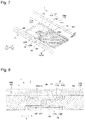
Fig. 4 is a perspective view illustrating how the liquid vessel illustrated inFig. 3 is assembled by engagement. -
Fig. 5 is a disassembled perspective view illustrating a state wherein the first member and the second member illustrated inFig. 4 have been disassembled. -
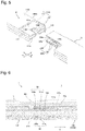
Fig. 6 is a cross-sectional view illustrating the liquid vessel taken along line VI-VI ofFig. 4 . -
Fig. 7 is a perspective view illustrating a state wherein a portion of the liquid vessel is broken. -
Fig. 8 is a cross-sectional view illustrating the liquid vessel taken along line IIX-IIX ofFig. 4 . -
Fig. 9 is a cross-sectional view illustrating the liquid vessel taken along line IX-IX ofFig. 4 . -
Fig. 10 is a cross-sectional view illustrating the liquid vessel taken along line X-X ofFig. 4 . -
Fig. 11 is a perspective view illustrating a first modification of the liquid vessel according to the first embodiment of the present invention. -
Fig. 12 is a perspective view illustrating a second modification of the liquid vessel according to the first embodiment of the present invention. -
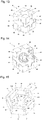
Fig. 13 is a perspective view illustrating a third modification of the liquid vessel according to the first embodiment of the present invention. -
Fig. 14 is a perspective view illustrating a state wherein some members have been removed from the liquid vessel illustrated inFig. 13 . -
Fig. 15 is a perspective view illustrating a fourth modification of the liquid vessel according to the first embodiment of the present invention. -
Fig. 16 is a perspective view illustrating a fifth modification of the liquid vessel according to the first embodiment of the present invention. -
Fig. 17 is a perspective view illustrating a state wherein some members have been removed from the liquid vessel illustrated inFig. 16 . -
Fig. 18 is a perspective view illustrating a sixth modification of the liquid vessel according to the first embodiment of the present invention. -
Fig. 19 is a perspective view illustrating a second embodiment of the liquid vessel according to the present invention. -
Fig. 20 is a perspective view illustrating a state wherein a third member is removed from the liquid vessel illustrated inFig. 19 . -
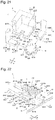
Fig. 21 is a disassembled perspective view illustrating a state wherein the liquid vessel illustrated inFig. 20 has been disassembled. -
Fig. 22 is a perspective view illustrating how the liquid vessel illustrated inFig. 21 is assembled by engagement. -
Fig. 23 is a disassembled perspective view illustrating a state wherein the first member and the second member illustrated inFig. 22 has been disassembled. -
Fig. 24 is a cross-sectional view illustrating the liquid vessel taken along line XXIV-XXIV ofFig. 22 . -
Fig. 25 is a cross-sectional view illustrating the liquid vessel taken along line XXV-XXV ofFig. 22 . -
Fig. 26 is a cross-sectional view illustrating the liquid vessel taken along line XXVI-XXVI ofFig. 22 . -
Fig. 27 is a cross-sectional view illustrating the liquid vessel taken along line XXVII-XXVII ofFig. 22 . -
Fig. 28 is a perspective view illustrating a third embodiment of the liquid vessel according to the present invention. -
Fig. 29 is a perspective view illustrating a state wherein a third member is removed from the liquid vessel illustrated inFig. 28 . -
Fig. 30 is a disassembled perspective view illustrating a state wherein the liquid vessel illustrated inFig. 29 has been disassembled. -
Fig. 31 is a perspective view illustrating how the liquid vessel illustrated inFig. 30 is assembled by engagement. -
Fig. 32 is a cross-sectional view illustrating the liquid vessel taken along line XXXII-XXXII ofFig. 31 . -
Fig. 33 is a cross-sectional view illustrating the liquid vessel taken along line XXXIII-XXXIII ofFig. 31 . -
Fig. 34 is a cross-sectional view illustrating the liquid vessel taken along line XXXIV-XXXIV ofFig. 31 . - Embodiments of the present invention will be described in reference to the accompanying drawings. It should be noted that the present invention is not limited to the embodiments described below, and that various changes and modifications are made possible in an optional way within the scope of the present invention. In the drawings referred to below, the scales, the numbers or the like of respective structures are shown in a different manner from those of actual structures in some cases in order to readily understand the respective structures.
- As illustrated in
Figs. 1 and 2 , theliquid vessel 1 according to this embodiment of the present invention includes abottom portion 10 formed in a square shape, and awall portion 15 formed in a square frame along an outer edge of thebottom portion 10. Thewall portion 15 extends so as to rise from the outer edge (periphery) of thebottom portion 10 in a depth direction of theliquid vessel 1. Theliquid vessel 1 is open on an opposite side of thebottom portion 10. Theliquid vessel 1 holds a liquid L in an inner space I defined by thebottom portion 10 and thewall portion 15. - Specifically, the
liquid vessel 1 is assembled from a plurality offirst members 11, asecond member 12 and a plurality ofthird members 13. Thesecond member 12 is disposed in a central area of thebottom portion 10. Thefirst members 11 are engaged with thesecond member 12. Thethird members 13 are engaged with thesecond member 12 and thefirst members 11. With regard to thefirst members 11, thesecond member 12 and thethird members 13, the peripheral edge of a main surface of each member is called an end portion. The engagement is made between facing end portions of thefirst members 11, thesecond member 12 and thethird members 13. - As illustrated in
Fig. 3 , eachfirst member 11 includes a firstjoint portion 1101 and a secondjoint portion 1102. The firstjoint portion 1101 forms a part of thebottom portion 10 of the liquid vessel 1 (seeFig. 1 ). The secondjoint portion 1102 extends from an outer end portion 1101a of the firstjoint portion 1101 so as to intersect the depth direction of theliquid vessel 1. The second joint portion forms a part of the wall portion 15 (seeFig. 1 ). - As illustrated in
Figs. 4 and5 , eachfirst member 11 has third recessedportions 117 on respective sides. The firstjoint portion 1101 of eachfirst member 11 extends from thewall portion 15 of the liquid vessel 1 (seeFig. 1 ) to thesecond member 12. The firstjoint portion 1101 has a firstengageable projecting portion 1110 formed on an end portion (hereinbelow, referred to as inner end portion) 1101b facing a central area of theliquid vessel 1. The firstengageable projecting portion 1110 further includes afirst projection 111 and asecond recess 116. - The
first projection 111 has a pair of first projectingsurfaces second recess 116 has a pair of first recessedside surfaces - As illustrated in
Fig. 3 , thesecond member 12 is disposed in the central area of the bottom portion 15 (seeFig. 1 ). The firstengageable projecting portion 1110 of each firstjoint portion 1101 is engaged with thesecond member 12. Thesecond member 12 has abase 19 and a plurality of second engageable recessedportions 1210 formed on the periphery of thebase 19. - The second engageable recessed
portions 1210 are circumferentially disposed at equal intervals so as to radially project from an outer periphery of the base 19 toward an external space O of theliquid vessel 1. - As illustrated in
Figs. 5, 6 and7 , each second engageable recessedportion 1210 includes afirst recess 125 engageable with its correspondingfirst projection 111 and a pair ofsecond projections 122 formed on the first recessedportion 125. Each first recessedportion 125 has a pair of first recessedsurfaces second projection 122 has a pair of projectingside surfaces - The
first projection 111 of each firstengageable projecting portion 1110 is engaged with thefirst recess 125 of its corresponding second engageable recessedportion 1210 to form a firstengageable portion 101. - Each
first projection 111 is engaged with its corresponding first recessedportion 125 to form a first narrow space S1 defined by one 111a of its paired first projectingsurfaces surfaces surfaces surfaces - Thus, each first
engageable portion 101 has a pair of the first narrow spaces S1 and S2. Each of the paired first narrow spaces S1 and S2 has a gap formed as a space that prevents the liquid L in theliquid vessel 1 from flowing out. In other words, the gap formed in each of the paired first narrow spaces S1 and S2 has a size that does not serve as a route allowing the liquid L to pass therethrough. This is also applicable to the narrow spaces described later. - In each pair of first narrow spaces S1 and S2, the gap is formed so as to extend in an engagement direction of its corresponding
first member 11 and the second member 12 (directions indicated by an arrow A) and in an intersecting direction as viewed from a direction along a bottom surface (inner surface) 10a of the liquid vessel 1 (i.e. the depth direction of the liquid vessel 1). - It is not essential that the gap of each pair of first narrow spaces S1 and S2 have a constant size. It is sufficient that the gap has a smaller size than a certain value. The gap may entirely or partly have a size of zero or have a size varying from position to position. This is also applicable to the gaps of the other narrow spaces described later.
- Each
second recess 116 has its paired first recessedside surfaces portion 122 has its paired projectingside surfaces second recess 116 of each firstengageable projecting portion 1110 is engaged with the second projectingportions 122 of its correspondingsecond engageable recess 1210 to form a secondengageable portion 102. - Each
second recess 116 is engaged with its corresponding second projectingportions 122 to form a second narrow space S3 defined by one 116a of its paired first recessedside surfaces side surfaces side surfaces side surfaces - In other words, each second
engageable portion 102 has its paired second narrow spaces S3 and S4. Each of the second narrow spaces S3 and S4 has a gap formed as a space that prevents the liquid L in theliquid vessel 1 from flowing out. In each of the paired second narrow spaces S3 and S4, the gap is formed so as to extend in the engagement direction of its correspondingfirst member 11 and the second member 12 (directions indicated by an arrow A) and in the direction along the bottom surface (inner surface) 10a of theliquid vessel 1. - Returning to
Figs. 2 and3 , thesecond member 12 and the firstjoint portion 1101 of eachfirst member 11 form a part of thebottom portion 10 of the liquid vessel 1 (seeFig. 1 ) in a state wherein eachfirst projection 111 is engaged with its correspondingfirst recess 125 while eachsecond projection 122 is engaged with its corresponding second recess 116 (seeFig. 7 as well). - Each second
joint portion 1102 extends in a direction intersecting its corresponding first joint portion 1101 (in other words, in the depth direction) such that each secondjoint portion 1102 forms a part of thewall portion 15 of the liquid vessel 1 (seeFig. 1 ). - Each
third member 13 has athird projection 133 engaged with the third recessedportion 117 of its correspondingfirst member 11 and athird recess 127 of thesecond member 12. - Each
third member 13 has a firstflat area 1305 and a secondflat area 1306. Further, eachthird member 13 has athird projection 133 engageable with the third recessedportion 117 of its correspondingfirst member 11 and thethird recess 127 of thesecond member 12. - As illustrated in
Figs. 8 and9 , the third recessedportion 117 of eachfirst member 11 includes a pair of third recessedsurfaces third projection 133 includes a pair of third projectingsurfaces - Each
third projection 133 is engaged with the firstjoint portion 1101 of its correspondingfirst member 11 in a direction (directions indicated by an arrow B) intersecting the engagement direction of thefirst member 11 and the second member 12 (directions indicated by an arrow A). - Further, the
third recess 127 of thesecond member 12 includes a pair of third recessedsurfaces third projection 133 is engaged with thethird recess 127 of thesecond member 12 in the direction (directions indicated by the arrow B) intersecting the engagement direction of thefirst member 11 and the second member 12 (directions indicated by an arrow A). - The
second member 12 and eachthird projection 133 form a thirdengageable portion 103 such that each firstjoint portion 1101 and the correspondingthird projection 133 form a thirdengageable portion 103. - Each
third projection 133 is engaged with the third recessedportion 117 of its corresponding first member 11 (first joint portion 1101) to form a third narrow space S5 defined by the third projectingsurface 133a of thisthird projection 133 and the third recessedsurface 117a of this third recessedportion 117. Likewise, a third narrow space S6 is formed, being defined by the third projectingsurface 133b of thisthird projection 133 and the third recessedsurface 117b of this third recessedportion 117. - Each of the third narrow spaces S5 and S6 has a gap formed as a space that prevents the liquid L in the
liquid vessel 1 from flowing out. In each of the third narrow spaces S5 and S6, the gap is formed so as to extend in a direction intersecting the engagement direction of its correspondingfirst member 11 and thesecond member 12 and in an intersecting direction (the depth direction of the liquid vessel 1) seen from the direction along thebottom surface 10a of theliquid vessel 1. - Each
third projection 133 is engaged with thethird recess 127 of thesecond member 12 to form a third narrow space S5 defined by the third projectingsurface 133a of thisthird projection 133 and the third recessedsurface 127a of thisthird recess 127
as in the other portions of the third narrow space S5 formed by the otherthird projections 133 and the otherfirst members 11. The third projectingsurface 133b of a third projectingportion 133 and the third recessedsurface 127b of its corresponding third recessedportion 127 form a third narrow space S6 as in the other portions of the third narrow spaces S6 formed by the otherthird projections 133 and the otherfirst members 11. - As illustrated in
Figs. 7 and10 , thefirst members 11 and thesecond member 12 are combined so as to be brought into contact with each other. When the liquid vessel is subjected, for example, to deformation caused by an earthquake or to an installation error, a space P1 is formed between aleading edge 111c of eachfirst projection 111 and a bottom 125c of each first recess 125 (seeFig. 6 ). - In the first embodiment, each space P1 never communicates with the inner space I of the
liquid vessel 1. A leading edge 133c of each third projectingportion 133 and a bottom 117c of its corresponding third recessedportion 117 are combined so as to be brought into contact with each other. When the liquid vessel is subjected, for example, to deformation caused by an earthquake or to an installation error, a space P2 is formed between the combined leading edge and bottom. In the first embodiment, each space P2 never communicates with the external space O of theliquid vessel 1. This is because measures are taken such that the liquid L that has entered in the space P1 is prevented from flowing into the space P2. - In other words, in the first embodiment, each second narrow space S3 is formed between its corresponding space P1 and its corresponding space P2, each second narrow space S3 is interposed between its corresponding first narrow space S1 and its corresponding third narrow space S5, and each first narrow space S1 and its corresponding third narrow space S5 communicate each other through its corresponding second narrow space S3.
- In a case where there is a single engageable portion unlike the first embodiment, when engagement is shifted to form a space, this space serves as a liquid route. Further, when displacement is made in other directions than the engagement direction, a liquid route is generated because there is no degree of freedom in the deformation among members.
- In a case where engagement is made at two locations unlike the first embodiment, when the engagement is shifted to form spaces, some of the spaces do not serves as a liquid route, although the other spaces serve as a liquid route. Further, when displacement is made in other directions than the engagement direction, a liquid route is generated because there is no degree of freedom in the deformation among members.
- In contrast, in the first embodiment, when the first engageable portions and their corresponding second engageable portions are shifted to form spaces, some of the spaces do not serve as a liquid route, although the other spaces serve as a liquid route. Nevertheless, the provision of the third engageable portions blocks the liquid route in the other spaces to prevent a liquid from leaking outwardly. Further, the provision of the third engageable portions ensures a degree of freedom in the deformation among members with respect to the displacement of a first engageable portion and its corresponding second engageable portion in other directions than the engagement direction. Even when shifting is made in a direction toward or away from a third engageable portion to form a space, no liquid route is formed.
- As described above, the provision of such sets of three engageable portions according to the embodiment of the present invention ensures not only a degree of freedom in a single engagement direction but also a degree of freedom in engagement directions intersecting the single engagement direction. Further, even when engagement is shifted to generate a space, no liquid route is formed from the inner space of the liquid vessel to the external space of the liquid vessel so long as the engagement is maintained.
- In other words, even when external forces are generated in two directions by an earthquake or another external factor after installation of the
liquid vessel 1, the provision of such sets of three engageable portions according to the embodiment of the present invention causes nothing more than shifting among thefirst members 11, thesecond member 12 and thethird members 13, and no liquid L leaks out so long as the engaged state of the combined members is maintained. - The provision of such sets of three engageable portions according to the embodiment of the present invention increases the tolerance to the installation accuracy in installation of the respective members because it is sufficient to pay attention only to the dimensional accuracy of the respective members.
- It should be noted that the size of the spaces formed in the engageable portions may be defined by the lengths of the projections and the lengths of the recesses in the engageable portions in the engagement directions. From this point of view, it is sufficient to estimate how much shifting would occur in each engageable portion and to set the lengths of the projections and the lengths of the recesses in the engageable portions in the engagement directions to have greater lengths than the estimated shifting lengths so as to prevent disengagement.
- Now, how to calculate the gap of each narrow space will be explained. In order to prevent the liquid L from leaking out, the following formula may be satisfied:

- GAP: the gap of each narrow space (first to third narrow spaces S1 to S6)
- σ: the surface tension of a held liquid
- θ: the contact angle of the held liquid to a liquid vessel
- ρ: the density of the held liquid
- g: gravity acceleration
- d: the height of the liquid surface of the held liquid in the liquid vessel
- For example, when the liquid L is a molten metal of tin held in a
liquid vessel 1 made of carbon, the allowable gap of each narrow space will be specified below. Here, the molten metal of tin has a depth set at 50 mm. - In this case, the molten metal of tin has a surface tension of 0.5 N/m and a contact angle of 135 degrees to carbon and a density of 7,000 kg/m3. Based on these values, it is sufficient that the gap of each narrow space is not greater than 0.2 mm. Conversely, even when there is a narrow space having a gap of about 0.1 mm, the molten metal of tin is prevented from flowing out.
- For example, when the liquid L is molten glass held in a
liquid vessel 1 made of carbon, the allowable gap of each narrow space will be specified below. Here, the molten glass has a depth set at 50 mm. - In this case, the molten glass has a surface tension of 0.3 N/m and a contact angle of 135 degrees to carbon and a density of 2,500 kg/m3. Based on these values, it is sufficient that the gap of each narrow space is not greater than 0.35 mm. Conversely, even when there is a narrow space having a gap of about 0.3 mm, the molten glass is prevented from flowing out.
- For example, when the liquid L is water held in a
liquid vessel 1 having water repellency, the allowable gap of each narrow space will be specified below. Here, the water has a depth set at 50 mm. - In this case, the water has a surface tension of 0.072 N/m and a contact angle of 135 degrees to the
liquid vessel 1 having water repellency and a density of 1,000 kg/m3. Based on these values, it is sufficient that the gap of each narrow space is not greater than 0.2 mm. - It is possible to make up the
liquid vessel 1 in a leakage-free manner by designing the respective narrow spaces as described above. Because it is not necessary to set the gap of each narrow space to zero as described above, and because it is sufficient to set the gap of each narrow space to not greater than a predetermined value, it is not necessary pay more attention than necessary on the production of the respectiveconstituent members liquid vessel 1 according to the present invention. - As described about the
liquid vessel 1 according to the first embodiment, the liquid L is prevented from entering the respective narrow spaces by its surface tension. - In other words, even when the occurrence of deformation by an earthquake or an installation error causes a space P1 to be formed between a
first member 11 and thesecond member 12 configured so as to be brought into contact with each other, and when the liquid L flows into the space P1, the provision of sets of a first narrow space S1, a second narrow space S3 and a third narrow space S5 can prevent the liquid from flowing out into their corresponding space P2. The inside of theliquid vessel 1 is made of the plurality offirst members 11, thesecond member 12 and the plurality ofthird members 13. Thus, the liquid L can be prevented from flowing out from the inner space I of the liquid vessel to the external space O. - As describe above, the plurality of
first members 11, thesecond member 12 and the plurality ofthird members 13 can be all engaged as illustrated inFigs. 2 and3 to easily make up theliquid vessel 1 in a large size of prefabricated form. It is impossible to produce the structure of such a liquid vessel by using of the method of laying bricks. - Specifically, the
liquid vessel 1 can be assembled in a large size so as to have thebottom portion 10 formed in a square shape in a planar view and thewall portion 15 formed in a square frame along the outer edge of thebottom portion 10. - The
liquid vessel 1 can be made up in a large size of prefabricated form by a simple structure that eachfirst member 11 is merely provided with a firstengageable projecting portion 1110 and a third recessedportion 117, thesecond member 12 is merely provided with the second engageable recessedportions 1210 and the third recessedportion 127, and eachthird member 13 is merely provided with a third projectingportion 133. - Further, the
second member 12 is provided with the plurality of second engageable recessedportions 1210, and thefirst members 11 are engaged with the second engageable recessedportions 1210. Thus, the plurality offirst members 11 are engaged with the singlesecond member 12. The number of the parts required for assembling theliquid vessel 1 can be minimized to simplify the structure. - The
third members 13 are engaged with thefirst members 11 and thesecond member 12 to form thebottom portion 10 and thewall portion 15 of theliquid vessel 1 for example. Thus, the number of the parts required for assembling theliquid vessel 1 can be further minimized to simplify the structure. - Although explanation of the
liquid vessel 1 according to the first embodiment has been made about a case where the firstjoint portion 1101 of eachfirst member 11 is provided with a firstengageable projecting portion 1110, and thesecond member 12 is provided with the second engageable recessedportions 1210, the present invention is not limited to such a case. Conversely, the firstjoint portions 1101 of thefirst members 11 may be interchanged with the second engageable recessedportions 1210 of thesecond member 12 as another case. - With regard to the design of such sets of three engageable portions according to the embodiment of the present invention, each set of three engageable portions is formed to have a first narrow space, a second narrow space and a third narrow space formed without a large gap being formed between engaged members.
- Now, first to seventh modifications of the first embodiment will be described in reference to
Fig. 11 to Fig. 18 . - As illustrated in
Fig. 11 , theliquid vessel 2 according to this modification is configured so as to have the same structure as theliquid vessel 1 according to the first embodiment except that thethird members 13 are replaced withthird members 23. - Each
third member 23 entirely has a uniform plate thickness T1. The plate thickness T1 is set to a thickness engageable with the third recessedportion 217 of afirst member 21 to be engaged. In other words, eachthird member 23 has a plate thickness T1 equal to the thickness of eachthird projection 233. - In this manner, the entire plate thickness T1 of the
third members 23 can be reduced to a thickness equal to the thickness of eachthird projection 233. Thus, the size of the plate thickness T1 of thethird members 23 can be minimized to reduce the weight of theliquid vessel 2. - As illustrated in
Fig. 12 , theliquid vessel 3 according to this modification includes a plurality offirst members 31, a plurality ofsecond members 32 and a plurality ofthird members 33. Further, theliquid vessel 3 includes afourth member 34, a plurality offifth members 35 and a plurality ofsixth members 36. - The
fourth member 34 is disposed in a central area of a bottom portion of theliquid vessel 3 and is formed in a square shape in a planar view. - Each
fifth member 35 is engaged mainly between its adjacentfirst members 31 as in therespective members fifth members 35 are disposed at positions opposed torespective sides 34a to 34d of thefourth member 34. Eachfifth member 35 is formed in an L-character shape in a side view and includes aportion 35b forming a part of the bottom portion of theliquid vessel 3 and aportion 35a forming a part of a wall portion of theliquid vessel 3. - Each
sixth member 36 is engaged between its adjacentfifth member 35 and thefourth member 34 opposing each other and between its adjacent pair ofsecond members 32 as in therespective members sixth member 36 forms a part of the bottom portion of theliquid vessel 3. - The wall portion of the
liquid vessel 3 is formed in a single layer and has a height of H1. - The
fourth member 34 is disposed in a central area of the bottom portion of theliquid vessel 3, and eachfifth member 35 is engaged between its adjacentfirst members 31. Thus, the respective sides of theliquid vessel 3 can have longer lengths L1 and L2 than the sides of theliquid vessel 1 according to the first embodiment. In other words, the second modification allows theliquid vessel 3 to be produced in a larger size of prefabricated form than theliquid vessel 1. - Although explanation of the
liquid vessel 3 according to the first modification has been made about a case where the wall portion of theliquid vessel 3 is formed in a single layer and have a height of H1, the liquid vessel is not limited to this mode. The wall portion of theliquid vessel 3 may have a plurality of stacked layers and a larger height H1. - As illustrated in
Figs. 13 and 14 , theliquid vessel 4 according to this modification includes a plurality offirst members 41, a plurality ofsecond members 42 and a plurality ofthird members 43. In eachfirst member 41, the secondjoint portion 1102 of eachfirst member 11 according to the first embodiment (seeFig. 3 ) is replaced with firstjoint portions 1101. In other words, eachfirst member 41 is configured to have a pair of firstjoint portions 1101 formed in an L-character shape in a side view. - Each
third member 43 has an additional third projection (not shown) formed on sides corresponding to the opening sides of thethird members 13 according to the first embodiment (seeFig. 3 ). In other words, each third member has a third projection extending from all peripheral sides. - In the
liquid vessel 4, the plurality offirst member 41, the plurality ofsecond member 42 and the plurality ofthird members 43 are engaged as in therespective members first members 41, the plurality ofsecond members 42 and the plurality ofthird members 43 are engaged to form theliquid vessel 4 in a fully-closed state with no opening. In other words, theliquid vessel 4 is provided as a prefabricated liquid vessel wherein the opening opposite to the bottom portion of theliquid vessel 1 according to the first embodiment is closed. - As illustrated in
Fig. 15 , theliquid vessel 5 according to this modification has abottom portion 50 formed in a hexagonal shape and awall portion 55 formed in a hexagonal frame along an outer edge (peripheral sides) of thebottom portion 50. - The
liquid vessel 5 has a plurality offirst members 51, asecond member 52 and a plurality ofthird members 53. In eachfirst member 51, the secondjoint portion 1102 of eachfirst member 11 according to the first embodiment (seeFig. 3 ) is formed in a V-character shape in a planar view, and the remaining portions are formed in the same as those of eachfirst member 11. - The
second member 52 is a member similar to thesecond member 12 according to the first embodiment (seeFig. 3 ). Thesecond member 52 has six second recessed projectingportions 526 radially projecting from a base 59 at equal intervals. Eachfirst member 51 has a firstjoint portion 5101 engaged with its corresponding second recessed projectingportion 526, being brought into contact with this second recessed projecting portion as in the first embodiment. - Each
third member 53 is disposed between its adjacentfirst members 51. In eachthird member 53, an area corresponding to the firstflat area 1305 of eachthird member 13 according to the first embodiment (seeFig. 3 ) is formed in a triangular shape in a planar view, and the remaining portions are the same as those of eachthird member 13. Eachthird member 53 is engaged with its adjacentfirst member 51 and thesecond member 52 as in the first embodiment. - As illustrated in
Figs. 16 and 17 , theliquid vessel 6 according to this modification has abottom portion 60 formed in an octagonal shape and awall portion 65 formed in an octagonal frame along an outer edge (peripheral sides) of thebottom portion 60. Theliquid vessel 6 includes a plurality offirst members 61, asecond member 62, a plurality ofthird members 63 and a plurality offourth members 64. - In each
first member 61, a portion corresponding to the secondjoint portion 1102 of eachfirst member 11 according to the first embodiment (seeFig. 3 ) is formed in a V-character shape in a planar view, and the remaining portions are formed in similar to those of eachfirst portion 11. - The
second member 62 is disposed a central area of thebottom portion 60 of theliquid vessel 6 so as to be formed in an octagonal shape in a planar view. The plurality offourth members 64 are engaged with peripheral sides of thesecond member 62. Eachfirst member 61 is engaged with its correspondingfourth member 64, being brought into contact with this fourth member. Eachthird member 63 is engaged between its adjacentfirst members 61. - The
first members 61, thesecond member 62, thethird members 63 and thefourth members 64 are engaged together as in thefirst members 11, thesecond member 12 and thethird members 13 according to the first member to produce a prefabricated liquid vessel. - As illustrated in
Fig. 18 , theliquid vessel 7 according to this modification has abottom portion 70 formed in a circular shape and awall portion 75 formed in a cylindrical shape along an outer edge (peripheral side) of thebottom portion 70. Theliquid vessel 7 includes a plurality offirst members 71, asecond member 72 andthird members 73. - In each
first member 71, the secondjoint portion 1102 of eachfirst member 11 according to the first embodiment (seeFig. 3 ) is formed in a curved shape in a planar view. - The
second member 72 is disposed in an central area of thebottom portion 70 of theliquid vessel 7. Thefirst members 71 are engaged with thesecond member 72, being brought into contact with the second member. Eachthird member 73 is engaged between its adjacentfirst members 71. In eachthird member 73, the secondflat area 1306 of eachthird member 13 according to the first embodiment (seeFig. 3 ) is formed in an arc-shape in a planar view. - The
first members 71, thesecond member 72 and thethird members 73 are engaged together as in thefirst members 11, thesecond member 12 and thethird member 13 according to the first embodiment to produce a prefabricated liquid vessel. - As described above, each of the
liquid vessels - Now, the
liquid vessels Figs. 19 to 27 andFigs. 28 to 34 . - As illustrated in
Figs. 19 and 20 , theliquid vessel 8 according to this embodiment is made up by abottom portion 80 formed in a square shape and awall portion 85 formed in a square frame along an outer edge (peripheral sides) of thebottom portion 80. Further, theliquid vessel 8 is opened on an opposite side of thebottom portion 80. Theliquid vessel 8 is configured so as to hold a liquid L in an inner space I defined by thebottom portion 80 and thewall portion 85. - Specifically, the
liquid vessel 8 is assembled from a plurality offirst members 81, asecond member 82 and a plurality ofthird members 83. Thesecond member 82 is disposed in a central area of thebottom portion 80. The plurality offirst members 81 are engaged with thesecond member 82. Eachthird member 83 is engaged with its adjacentfirst members 81 and thesecond member 82. - As illustrated in
Fig. 21 , eachfirst member 81 includes a firstjoint portion 8101 and a secondjoint portion 8102. The firstjoint portion 8101 forms a part of the bottom 80 of the liquid vessel 8 (seeFig. 19 ). The secondjoint portion 8102 extends from anouter end portion 8101a of the firstjoint portion 8101 to a depth direction of theliquid vessel 8. The secondjoint portion 8102 of each first member forms a part of thewall portion 85. - As illustrated in
Figs. 22 and23 , each firstjoint portion 8101 includes a first innerjoint surface 8101c, a first outerjoint surface 8101d and a pair of first sidejoint surfaces 8101e. Each first innerjoint surface 8101c is disposed on a side of the inner space I of theliquid vessel 8. Each first outerjoint surface 8101d is disposed on a side of an external space O of theliquid vessel 8. One of paired first sidejoint surfaces 8101e is disposed to connect between one of both sides of the first innerjoint surface 8101c and one of both sides of the first outerjoint surface 8101d. The other one of the paired firstside point surfaces 8101e is disposed to connect between the other side of the first innerjoint surface 8101c and the other side of the first outerjoint surface 8101d. - Each first
joint portion 8101 is formed in a rectangular shape in section by its first innerjoint surface 8101c, first outerjoint surface 8101d and paired first sidejoint surfaces 8101e. - Each
joint portion 8101 extends from thewall portion 85 of the liquid vessel 8 (seeFig. 19 ) to thesecond member 82. Each firstjoint portion 8101 includes a firstengageable projecting portion 8110 formed on an end portion (hereinbelow, referred to as inner end portion) 8101b close to a central side of theliquid vessel 8. Each firstengageable projecting portion 8110 is provided with afirst projection 811 and asecond projection 812. - Each
first projection 811 is formed in a rectangular shape in section and projects toward a central area side of theliquid vessel 8 in a direction along a bottom surface (inner surface) 80a of theliquid vessel 8. - Each
second projection 812 is formed on a side of abottom surface 80a of theliquid vessel 8 with respect to its correspondingfirst projection 811. Eachsecond projection 812 projects toward the central area side of theliquid vessel 8 in the direction along thebottom surface 80a of theliquid vessel 8. - Returning to
Fig. 21 , each firstjoint portion 8101 has a secondjoint portion 8102 formed on an outer end portion (opposite end portion) 8101a of its corresponding firstengageable projecting portion 8110. Each secondjoint portion 8102 extends in a direction intersecting its corresponding first joint portion 8101 (in other words, a depth direction of the liquid vessel 8). The secondjoint portions 8102 are formed in a rectangular shape in section as in the firstjoint portions 8101. - The
second member 82 is disposed at a central portion of the bottom portion 80 (seeFig. 19 ). The firstengageable projecting portion 8110 of each firstjoint portion 8101 is engaged with thesecond member 82. Thesecond member 82 includes a base 89 forming the central portion and a plurality of second engageable recessedportions 8210 formed the periphery of thebase 89. - The second engageable recessed
portions 8210 are disposed at four positions on the outer periphery of thebase 89. In other words, the second engageable recessedportions 8210 are circumferentially disposed at equal intervals so as to radially project from the outer periphery of the base 89 toward an external space O of theliquid vessel 8. Each second engageable recessedportion 8210 includes afirst recess 825 engageable with its correspondingfirst projection 811 and asecond recess 826 formed at thefirst recess 825. - As illustrated in
Figs. 22 and23 , each secondengageable portion 8210 includes a first innerengageable surface 8210a, a first outerengageable surface 8210b and a pair of firstengageable side surfaces 8210c. Each first innerengageable surface 8210a is disposed on a side of the inner space I of theliquid vessel 8. Each first outerengageable surface 8210b is disposed on a side of the external space O of theliquid vessel 8. One of paired firstengageable side surfaces 8210c is disposed to connect between one side of its corresponding first innerengageable surface 8210a and one side of its corresponding outerengageable surface 8210b. The other one of paired firstengageable side surfaces 8210c is disposed to connect between the other side of its corresponding first innerengageable surface 8210a and the other side of its corresponding first outerengageable surface 8210b. - Each second engageable recessed
portion 8210 has an outer shape formed in a rectangular shape in section by its corresponding first innerengageable surface 8210a, first outerengageable surface 8210b and paired firstengageable side surfaces 8210c. - Each
first recess 825 is open so as to be engageable with its correspondingfirst projection 811. Eachsecond recess 826 is formed in a part of its corresponding second engageable recessedportion 8210 close to thebottom surface 80a of theliquid vessel 8 and is formed in a groove shape so as to be engageable with its correspondingsecond projection 812. - Each
first projection 811 is engaged with its correspondingfirst recess 825 to form a firstengageable portion 801. Eachsecond projection 812 is engaged with its correspondingsecond recess 826 to form a secondengageable portion 802. - The
first projections 811 are engaged with thefirst recesses 825, and thesecond projections 812 are engaged with thesecond recesses 826, causing the firstjoint portions 8101 to radially extend from thesecond member 82. - As illustrated in
Fig. 24 , the first innerjoint surface 8101c of each firstjoint portion 8101 and the first innerengageable surface 8210a of its corresponding second engageable recessedportion 8210 are disposed to be flush with each other. The first outerjoint surface 8101d of each firstjoint portion 8101 and the first outerengageable surface 8210b of its corresponding second engageable recessedportion 8210 are disposed to be flush with each other. - Each first projecting
portion 811 includes a pair of first projectingsurfaces first recess 825 includes a pair of first recessedsurfaces portion 811 is engaged with its correspondingfirst recess 825 to form a first narrow space S7 defined by one 811a of its paired first projectingsurfaces surfaces surfaces surfaces - Thus, each first
engageable portion 801 includes a pair of first narrow spaces S7 and S8. Each of paired first narrow spaces S7 and S8 has a gap formed as a space that prevents the liquid L in theliquid vessel 8 from flowing out. In other words, each of the first narrow spaces S7 and S8 is formed to have such a gap that the liquid L is prevented from entering each of the first narrow spaces S7 and S8 by surface tension. - In each of the paired first narrow spaces S7 and S8, the gap is formed so as to extend in an engagement direction of the
first members 81 and the second member 82 (directions indicated by an arrow A) and in an intersecting direction as viewed from a direction along the bottom surface (inner surface) 80a of the liquid vessel 8 (i.e. the depth direction of the liquid vessel 8). - Returning to
Fig. 22 , each second projectingportion 812 has a pair of second projectingside surfaces 812a and 812b. Eachsecond recess 826 includes a pair of second recessedside surfaces portion 812 is engaged with its correspondingsecond recess 826 to form a second narrow space S9 defined by one 812a of its paired second projectingside surfaces 812a and 812b and one 826a of its corresponding paired second recessedside surfaces side surfaces 812a and 812b and the other one 826b of its corresponding paired second recessedside surfaces - Thus, each second
engageable portion 802 includes a pair of second narrow spaces S9 and S10. Each of the paired second narrow spaces S9 and S10 has a gap formed as a space that prevents the liquid L in theliquid vessel 8 from flowing out. In other words, each of the paired second narrow spaces S9 and S10 is formed so as to have a gap sized to prevent the liquid L from entering their corresponding first narrow spaces S7, S8 by surface tension. In each of the paired second narrow spaces S9 and S10, the gap is formed so as to extend in the engagement direction of thefirst members 81 and thesecond member 82 and in the direction along the bottom surface (inner surface) 80a of theliquid vessel 8. - As illustrated in
Fig. 21 , eachthird member 83 includes a firstflat area 8305 and a secondflat area 8306. Each firstflat area 8305 is formed in a rectangular shape in a planar view and forms a part of thebottom portion 80 of the liquid vessel 8 (seeFig. 19 ). Each secondflat area 8306 is bent in an L-character shape along an outer edge (peripheral side) of its corresponding firstflat area 8305 in a planar view and forms a part of thewall portion 85 of the liquid vessel 8 (seeFig. 9 ). - Further, each
third member 83 includes third recessedportions 833 engageable with its adjacentfirst members 81 and its adjacentsecond member 82. Each third recessedportion 833 has a third bottom recessedportion 837H formed at the firstflat area 8305 and a third wall recessedportion 837V formed at the secondflat area 8306. - Each third bottom recessed
portion 837H is formed in a recessed shape in section so as to be engageable with the firstjoint portion 8101 of its adjacentfirst member 81 and thesecond member 82. Each third wall recessedportion 837V is formed in recessed shape in section so as to be engageable with the secondjoint portion 8102 of its adjacentfirst member 81. - Specifically, each
third member 83 is engaged with third projectingportions first members 81 and thesecond member 82, being brought into contact with these third projecting portions in a direction (directions indicated by an arrow B) intersecting the engagement direction of this adjacentfirst member 81 and the second member 82 (directions indicated by an arrow A). - Each
third member 83 is engaged with its adjacentfirst member 81 in such a state that the plurality offirst members 81 are engaged with thesecond member 82. - As illustrated in
Figs. 24, 25 and26 , each third bottom recessedportion 837H is formed in a recessed shape in section and includes a third inner bottom recessed surface 837Ha and a third outer bottom recessed surface 837Hb. The third inner bottom recessed surfaces 837Ha and the third outer bottom recessed surfaces 837Hb are formed along thebottom surface 80a of theliquid vessel 8. - Each third bottom recessed portion H is engaged with the first
joint portion 8101 of its adjacentfirst member 81 in a direction (directions indicated by an arrow B) intersecting an engagement direction of its adjacentfirst member 81 and the second member 82 (directions indicated by an arrow A). Each firstjoint portion 8101 and its corresponding third bottom recessedportion 837H form a thirdengageable portion 803. Further, each third bottom recessedportion 837H is engaged with thesecond member 82 in a direction (directions indicated by an arrow B) intersecting the engagement direction of its adjacentfirst member 81 and the second member 82 (directions indicated by the arrow A). Thesecond member 82 and each third bottom recessedportion 837H form a thirdengageable portion 803. - Each third bottom recessed
portion 837H is engaged with the firstjoint portion 8101 of its adjacentfirst member 81 to form a third narrow space S11 defined by its third inner bottom recessed surface 837Ha and the first innerjoint surface 8101c of this firstjoint portion 8101. Each third outer bottom recessed surface 837Hb and the first outerjoint surface 8101d of its corresponding firstjoint portion 8101 form a third narrow space S12. - Further, each third bottom recessed
portion 837H is engaged with thesecond member 82 to form a third narrow space S11 defined by its third inner bottom recessed surface 837Ha and the first innerengageable surface 8210a of its corresponding firstjoint portion 8101. Each third outer bottom recessed surface 837Hb and the first outerengageable surface 8210b of its corresponding firstjoint portion 8101 form a third narrow space S12. In each of the third narrow spaces S11 and S12, the gap is formed as a space that prevents the liquid L in theliquid vessel 8 from flowing out. In each of the third narrow spaces S11 and S12, the gap is formed so as to extend in a direction intersecting the engagement direction of thefirst members 81 and thesecond member 82 and in an intersecting direction as viewed from the direction along thebottom surface 80a of the liquid vessel 8 (the depth direction of the liquid vessel 8). - As illustrated in
Figs. 20 and21 , the third recessed allportion 837V of each secondflat area 8306 is engaged with the second joint portion 3102 of its adjacentfirst member 81 to form a third narrow space S13 and a third narrow space S14. Each third narrow space S13 is continuous to its corresponding third narrow space S11 (seeFig. 24 ). Each third narrow space S14 is continuous to its corresponding third narrow space S12 (seeFig. 24 ). - Each of the third narrow spaces S13 and S14 has a gap formed as a space that prevents the liquid L in the
liquid vessel 8 from flowing out. In other words, each of the third narrow spaces S13 and S14 has a gap to prevent the liquid L from entering its corresponding narrow spaces S7 and S8 based on the relationship between the surface tension and the contact angle of the liquid. - As illustrated in
Figs. 22 and27 , the first projectingsurface 811a of each first projectingportion 811 and the first recessedsurface 825a of its correspondingfirst recess 825 form a first narrow space S7 on a side of thebottom surface 80a of theliquid vessel 8. The second projectingside surface 812a of each second projectingportion 812 and the second recessedside surface 826a of its correspondingsecond recess 826 form a second narrow space S9 on the side of thebottom surface 80a of theliquid vessel 8. The first engageableinner surface 8210a of each second engageable recessedportion 8210 and the third inner bottom recessed surface 837Ha of its corresponding third bottom recessedportion 837H form a third narrow space S11 on the side of thebottom surface 80a of theliquid vessel 8. - Each second narrow space S9 is interposed between its adjacent first narrow space S7 on the side of the
bottom surface 80a and its adjacent third narrow space S11 on the side of thebottom surface 80a, and each first narrow space S7 on the side of thebottom surface 80a is continuous to its adjacent third narrow space S11 on the side of thebottom surface 80a through their adjacent second narrow space S9. - Each
first member 81 and thesecond member 82 are brought into contact with each other so as to form a space P3 and a space P4 at their firstengageable portion 801 and their secondengageable portion 802 when the liquid vessel is subjected, for example, to deformation caused by an earthquake or to an installation error. The firstflat area 8305 of one of adjacentthird members 83 and the firstflat area 8305 of the other one of these adjacentthird members 83 are brought into contact with each other so as to form a space P5a between these adjacentthird members 83 brought into contact with each other, when the liquid vessel is subjected, for example, to deformation caused by an earthquake or to an installation error. - Further, each
first member 81 and its adjacentthird member 83 are brought into contact with each other so as to form a space P5b when the liquid vessel is subjected, for example, to deformation caused by an earthquake or to an installation error. - In the second embodiment, each space P4 never communicates with the external space O of the
liquid vessel 8. In the second embodiment, the space P3 between each second projectingportion 812 and its correspondingsecond recess 826 never communicates with the space P5a between the firstflat areas joint portion 8101. This is because measures are taken such that the liquid L that has entered in each space P3 is prevented from flowing into its corresponding space P4. - In other words, in the second embodiment, sets of a first narrow space S7, a second space S9 and a third space S11 are provided. Thus, such sets of a first narrow space S7, a second space S9 and a third space S11 avoid that the liquid L that flows into the spaces P3 from their corresponding spaces P5a flows into the spaces P4.
- The plurality of
first members 81, thesecond member 82 and the plurality ofthird members 83 can be all engaged as illustrated inFigs. 20 and21 to easily make up theliquid vessel 8 in a large size of prefabricated form. - Specifically, the
liquid vessel 8 can be assembled in a large size so as to have thebottom portion 80 formed in a square shape in a planar view and thewall portion 85 formed in a square frame along thebottom portion 80. - The
liquid vessel 8 can be made up in a large size of prefabricated form by a simple structure that eachfirst member 81 is merely provided with a first projectingportion 811 and a second projectingportion 812, thesecond member 82 is merely provided with thefirst recesses 825 and thesecond recesses 826, and eachthird member 13 is merely provided with a third recessedportion 833. - Further, the
second member 82 is provided with a plurality of second engageable recessedportions 8210, and thefirst members 11 are engaged with the second engageable recessedportions 8210. Thus, the plurality offirst members 81 are engaged with the singlesecond member 82. The number of the parts required for assembling theliquid vessel 8 can be minimized to simplify the structure. - The
third members 83 are engaged with thefirst members 81 and thesecond member 82 to form thebottom portion 80 and thewall portion 85 of theliquid vessel 8 for example. Thus, the number of the parts required for assembling theliquid vessel 8 can be further minimized to simplify the structure. - Although explanation of the
liquid vessel 8 according to the second embodiment has been made about a case where the firstjoint portion 8101 of eachfirst member 81 is provided with a firstengageable projecting portion 8110, and thesecond member 82 is provided with the second engageable recessedportions 8210, the present invention is not limited to such a case. As another case, each firstjoint portion 8101 may be provided with a second engageable recessedportion 8210, and thesecond member 82 may be provided with firstengageable projecting portions 8110. - As illustrated in
Figs. 28 and29 , theliquid vessel 9 according to this embodiment of the present invention includes abottom portion 90 formed in a square shape, and awall portion 95 formed in a square frame along an outer edge (peripheral sides) of thebottom portion 90. Theliquid vessel 9 is open on an opposite side of thebottom portion 90. Theliquid vessel 9 is configured to hold a liquid L in an inner space I defined by thebottom portion 90 and thewall portion 95. - Specifically, the
liquid vessel 9 is assembled from afirst member 91, asecond member 92 and a pair ofthird members - Explanation will be made, the engagement direction of the
first member 91 and thesecond member 92 being called directions indicated by an arrow A, and directions orthogonal to the directions indicated by the arrow A being called directions indicated by an arrow B. - The
first member 91 is disposed at a central position of theliquid vessel 9 in the directions indicated by the arrow B and on one side in the directions indicated by the arrow A. Thesecond member 92 is disposed at a central position of theliquid vessel 9 in the directions indicated by the arrow B and on the other side in the directions indicated by the arrow A. Each of thefirst member 91 and thesecond member 92 is formed in an L-character shape in a side view. Thefirst member 91 has aleading edge portion 911a engaged with aleading edge portion 922a of thesecond member 92. Thefirst member 91 has a third recessedportion 917 formed at one of lateral sides while thesecond member 92 has a third recessedportion 927 formed at one of lateral sides. Thefirst member 91 has a third projectingportion 913 formed on the other lateral side while thesecond member 92 has a third projectingportion 923 formed at the other lateral side. - The
third member 93A has third projectingportions 931 engaged with the third recessedportions third member 93B has a third recessedportion 937 engaged with the third projectingportions - As illustrated in
Figs. 30 ,31 and 32 , thefirst member 91 has a first projectingportion 911 engaged with a first recessedportion 925 of thesecond member 92 to form a firstengageable portion 901. The first projectingportion 911 has projecting side surfaces, one 911a of which forms a fourth narrow space S15 along with its corresponding one 925a of recessed side surfaces of the first recessedportion 925. The other projectingside surface 911b of the first projectingportion 911 forms a fourth narrow space S16 along with the other recessedside surface 925b of the first recessedportion 925. - Each of the fourth narrow spaces S15 and S16 has a gap formed as a space that prevents the liquid L in the
liquid vessel 9 from flowing out. - The
first member 91 has a second projectingportion 912 engaged with asecond recess 926 of thesecond member 92 to form a secondengageable portion 902. The second projectingportion 912 has a projectingside surface 912a, which forms a second narrow space S17 along with a recessedside surface 926a of thesecond recess 926. The second narrow space S17 has a gap formed as a space that prevents the liquid L in theliquid vessel 9 from flowing out. - The
third member 93B has a third recessedportion 937, which has a recessedsurface 937a to form a third narrow space S18 along with a projecting surface 922 on the other side of thesecond member 92. The third narrow space S18 has a gap formed as a space that prevents the liquid L in theliquid vessel 9 from flowing out. - Further, the
first member 91 has a fourth projectingportion 914 engaged with a fourth recessedportion 928 of thesecond member 92 to form a fourthengageable portion 904. The fourth projectingportion 928 has a recessedsurface 928a, which forms a first narrow space S19 along with a projecting surface 914a of the fourth projectingportion 914. The first narrow space S19 has a gap formed as a space that prevents the liquid L in theliquid vessel 9 from flowing out. - The second narrow space S17 is interposed between the first narrow space S19 and the third narrow space S18, and the first narrow space S19 is continuous to the third narrow space S18 through the second narrow space S17.
- Thus, the liquid L that flows into a space P6 is prevented from flowing into a space P8 through a space P8 by the first narrow space S19, the second narrow space S17 and the third narrow space S18.
- As illustrated in
Figs. 32 to 34 , in the one 903A of the third engageable portions, the third projectingportion 931 is engaged with the third recessedportions surface 917a of the third recessedportion 917 and a recessedsurface 927a of the third recessedportion 927 form one of third narrow spaces S20. - The one of the third narrow spaces S20 has a gap formed as a space that prevents the liquid L in the
liquid vessel 9 from flowing out. Thus, the liquid L that flows into a space P9 is prevented from flowing into a space P10 by the third narrow portion S20. - In the other third
engageable portion 903B, the third recessedportion 937 is engaged with the third projectingportion 913 of thefirst member 91 and the third projectingportion 923 of thesecond member 92. A recessedsurface 937a of the third recessedportion 937, a projectingsurface 913a of the third projectingportion 913 and a projectingsurface 923a of the third projectingportion 923 form other third narrow space S21. - The other third narrow space S21 has a gap formed as a space that prevents the liquid L in the
liquid vessel 9 from flowing out. Theliquid vessel 9 has an inner side defined by thefirst member 91, thesecond member 92 and the pairedthird members - Thus, the
first member 91, thesecond member 92 and the pairedthird members Figs. 28 to 34 to easily make up theliquid vessel 9 in a large size of prefabricated form. - Specifically, the
liquid vessel 9 can be assembled in a large size so as to have thebottom portion 90 formed in a square shape in a planar view and thewall portion 95 formed in a square frame along thebottom portion 90. - The liquid vessel according to the present invention is applicable to a vessel for holding various kinds of liquids in a wide range of fields. As a preferred example, the liquid vessel is usable as a molten metal bath for glass product production, which holds a liquid, such as molten metal for producing glass products, such as glass plates, by a float process, for example, disclosed in
WO2012/060197A . In the molten metal bath used in a float process, for example, molten metal, specifically molten tin, is held as the liquid L. - As another example, the liquid vessel is applicable to a bath for holding molten glass for producing glass products. As the bath for holding molten glass, the liquid vessel is applicable to a refiner for removing bubbles in molten glass after melding glass materials, a canal for forming molten glass by a down-draw process, or a forming apparatus called sword. Further, the liquid vessel according to the present invention may be used in the method for producing glass products such that a molten metal bath, a canal, a sword or the like that has been used in conventional glass production equipment is replaced by the vessel structure according to the present invention.
- The materials for forming the liquid vessel according to the present invention may be different, depending on the kinds of held liquids, and materials which are not eroded by a held liquid is normally used. For example, stainless steel is used. For example, as the materials required to be refractory, carbon, a boron nitride or the like may be used.
- The entire disclosure of Japanese Patent Application No.
2017-150857 filed on August 3, 2017 -
- L: Liquid, 1, 2, 3, 4, 5, 6, 7, 8 and 9: liquid vessel
- 10, 50, 6, 70, 80 and 90: bottom portion
- 10a and 80a: bottom surface (inner surface)
- 15, 55, 65, 75, 85 and 95: wall portion
- 11, 21, 31, 41, 51, 61, 71, 81 and 91: first member
- 12, 22, 32, 42, 52, 62, 72, 82 and 92: second member
- 13, 23, 33, 43, 53, 63, 73, 83, 93A and 93 B: third member
- 34, 64: fourth member, 35: fifth member, 36: sixth member
- 101, 801 and 901: first engageable portion
- 102, 802 and 902: second engageable portion
- 103, 803, 903A and 903B: third engageable portion
- S1, S2, S7, S8 and S19: first narrow space
- S3, S4, S9, S10 and S17: second narrow space
- S5, S6, S11, S12, S13, S14, S18, S20 and S21: third narrow space
- S15 and S16: fourth narrow space
- 111, 811 and 911: first projecting portion
- 122, 812 and 912: second projecting portion
- 133, 233, 813, 823, 913, 923 and 931: third projecting portion
- 914: fourth projecting portion, 125, 825 and 925: first recess
- 116, 826 and 926: second recess
- 117, 127, 217, 833, 917, 927 and 937: third recessed portion
- 928: fourth recessed portion, 1101, 5101 and 8101: first joint portion
- 1102 and 8102: second joint portion, 1305 and 8305: first flat area
- 1306 and 8306: second flat area
Claims (14)
- A liquid vessel for holding a liquid, comprising:at least a first member, a second member and a third member; anda first engageable portion and a second engageable portion being configured such that the first member and the second member are brought into contact with each other to be engaged, and a third engageable portion being configured such that the third member is brought into contact with the first member and the second member in a direction intersecting an engagement direction of the first member and the second member to be engaged with the first member and the second member.
- The liquid vessel according to Claim 1, wherein:the first engageable portion includes a first narrow space, which has a gap formed in the engagement direction of the first member and the second member and in an intersecting direction as viewed from a direction along an inner surface of the liquid vessel;the second engageable portion includes a second narrow space, which has a gap formed in the engagement direction of the first member and the second member and in the direction along the inner surface of the liquid vessel;the third engageable portion includes a third narrow space, which has a gap formed in a direction intersecting the engagement direction of the first member and the second member and in an intersecting direction as viewed from the direction along the inner surface of the liquid vessel;the second narrow space is interposed between the first narrow space and the third narrow space, and the first narrow space and the third narrow space is continuous to each other through the second narrow space; andthe liquid vessel includes a wall portion, the wall portion having an inner side defined by at least the third member, the wall portion extending in a depth direction of the liquid vessel from a bottom portion of the liquid vessel and a periphery of the bottom portion.
- The liquid vessel according to Claim 1 or 2, wherein:one member of the first member and the second member has a first projecting portion projecting in a direction along an inner surface of the liquid vessel and a first recessed portion formed in the first projecting portion;the other member of the first member and the second member has a second recessed portion engageable with the first projecting portion and a second projecting portion formed in the second recessed portion so as to be engageable with the first recessed portion;the third member has a third projecting portion engageable with the first member and the second member;the first projecting portion and the first recessed portion are engaged with each other to form a first narrow space;the second projecting portion and the second recessed portion are engaged with each other to form a second narrow space; andthe first member and the second member are engaged with the third projection to form a third narrow space.
- The liquid vessel according to Claim 1 or 2, wherein:one member of the first members and the second member has a first projecting portion projecting in a direction along an inner surface of the liquid vessel and a second projecting portion formed on the first projecting portion along the inner surface of the liquid vessel;the other member of the first member and the second member has a first recessed portion engageable with the first projecting portion and a second recessed portion formed in the first recessed portion so as to be engageable with the second projecting portion;the third member has a third recessed portion engageable with the first member and the second member;the first projecting portion and the first recessed portion are engaged with each other to form a first narrow space;the second projecting portion and the second recessed portion are engaged with each other to form a second narrow space; andthe first member and the second member are engaged with the third recessed portion to form a third narrow space.
- The liquid vessel according to any one of Claims 1 to 4, wherein:the other member of the first member and the second member is formed in a radial shape;the one member of the first member and the second member is engaged with the other member formed in a radial shape such that the one member is extended so as to have radial extensions; andthe third member is engaged between adjacent radial extensions of the one member.
- The liquid vessel according to Claim 5, wherein:the one member is engaged with the other member to have a first joint portion radially extending and a second joint portion extending in a direction intersecting the first joint portion from an opposite side of a side where both members re engaged; andthe third member has a first flat area engageable with the first joint portion and the second flat area engageable with the second joint portion.
- The liquid vessel according to any one of Claims 1 to 6, wherein:the liquid vessel has the bottom portion formed in a polygonal shape and the wall portion formed along the bottom portion; andthe liquid vessel is open on an opposite side of the bottom portion.
- The liquid vessel according to Claim 7, wherein the liquid vessel has the bottom portion formed in a square shape and the wall portion formed in a square frame along the bottom portion.
- The liquid vessel according to one of Claims 7 and 8, wherein the liquid vessel is closed on the opposite side of the bottom portion.
- The liquid vessel according to any one of Claims 1 to 9, wherein when the first narrow space, the second narrow space and the third narrow space has a gap of GAP, the GAP satisfies the following formula:

- The liquid vessel according to any one of Claims 1 to 10, wherein the liquid comprises molten glass.
- The liquid vessel according to any one of Claims 1 to 10, wherein the liquid comprises molten metal.
- A method for producing a glass product, comprising using molten glass held in the liquid vessel recited in any one of Claims 1 to 10.
- A method for producing a glass product, comprising holding a molten metal in the liquid vessel recited in any one of Claims 1 to 10, and floating molten glass on the molten metal to form the glass product.
Priority Applications (1)
| Application Number | Priority Date | Filing Date | Title |
|---|---|---|---|
| EP22160688.2A EP4043364B1 (en) | 2017-08-03 | 2018-07-30 | Liquid vessel and method therewith |
Applications Claiming Priority (2)
| Application Number | Priority Date | Filing Date | Title |
|---|---|---|---|
| JP2017150857 | 2017-08-03 | ||
| PCT/JP2018/028485 WO2019026852A1 (en) | 2017-08-03 | 2018-07-30 | Container for holding liquid |
Related Child Applications (2)
| Application Number | Title | Priority Date | Filing Date |
|---|---|---|---|
| EP22160688.2A Division EP4043364B1 (en) | 2017-08-03 | 2018-07-30 | Liquid vessel and method therewith |
| EP22160688.2A Division-Into EP4043364B1 (en) | 2017-08-03 | 2018-07-30 | Liquid vessel and method therewith |
Publications (3)
| Publication Number | Publication Date |
|---|---|
| EP3663234A1 true EP3663234A1 (en) | 2020-06-10 |
| EP3663234A4 EP3663234A4 (en) | 2021-06-30 |
| EP3663234B1 EP3663234B1 (en) | 2023-12-06 |
Family
ID=65232560
Family Applications (2)
| Application Number | Title | Priority Date | Filing Date |
|---|---|---|---|
| EP18840611.0A Active EP3663234B1 (en) | 2017-08-03 | 2018-07-30 | Container for holding liquid and methods therewith |
| EP22160688.2A Active EP4043364B1 (en) | 2017-08-03 | 2018-07-30 | Liquid vessel and method therewith |
Family Applications After (1)
| Application Number | Title | Priority Date | Filing Date |
|---|---|---|---|
| EP22160688.2A Active EP4043364B1 (en) | 2017-08-03 | 2018-07-30 | Liquid vessel and method therewith |
Country Status (6)
| Country | Link |
|---|---|
| US (1) | US11702243B2 (en) |
| EP (2) | EP3663234B1 (en) |
| JP (2) | JP6888680B2 (en) |
| CN (2) | CN110997524B (en) |
| TW (2) | TWI807964B (en) |
| WO (1) | WO2019026852A1 (en) |
Families Citing this family (1)
| Publication number | Priority date | Publication date | Assignee | Title |
|---|---|---|---|---|
| US11851357B2 (en) * | 2021-09-09 | 2023-12-26 | James William Masten, JR. | Method for forming shaped glass |
Family Cites Families (50)
| Publication number | Priority date | Publication date | Assignee | Title |
|---|---|---|---|---|
| FR1270366A (en) * | 1960-10-14 | 1961-08-25 | Prefabricated structure and elements for its construction | |
| FR1357788A (en) * | 1963-02-28 | 1964-04-10 | Anciens Etablissements Sadon | Large capacity tank for corrosive products |
| JPS493797Y1 (en) * | 1969-08-29 | 1974-01-30 | ||
| JPS519941A (en) * | 1974-07-15 | 1976-01-27 | Toshiba Machine Co Ltd | Shihenni ototsunoarumenzai |
| US4244486A (en) * | 1979-05-11 | 1981-01-13 | Ewald Jr Herbert J | Tank |
| JPS58143319U (en) * | 1982-03-19 | 1983-09-27 | 株式会社昭和丸筒 | Assembly type exterior body |
| CA1246890A (en) * | 1988-03-10 | 1988-12-20 | Paul J. Kruger | Composite panel, wall assembly and components therefor |
| US5155872A (en) * | 1990-10-25 | 1992-10-20 | Aymes Doniel G | Swimming pool with interlocking wall panels and liner-receiving top rail |
| US6902061B1 (en) * | 2000-09-29 | 2005-06-07 | Paul Elstone | Collapsible liquid box |
| JP2002314221A (en) * | 2001-04-16 | 2002-10-25 | Tokyo Kakoki Kk | Processing chamber and manufacturing method thereof |
| DE10133471B4 (en) * | 2001-07-10 | 2004-09-30 | Schott Glas | Trough for holding a melting bath made of glass or glass ceramic |
| FR2830850B1 (en) * | 2001-10-15 | 2003-12-26 | Glaverbel | SPACER RIDER HOLDER |
| CN1462713A (en) * | 2002-05-28 | 2003-12-24 | 岐阜塑料工业株式会社 | Assembling vessel |
| JP2004268989A (en) * | 2003-03-10 | 2004-09-30 | Fujikowa Industry Co Ltd | Foldable transport container |
| CA2531583C (en) * | 2003-07-07 | 2011-08-23 | Rodney M. Derifield | Insulated shipping containers |
| DE10335325B4 (en) * | 2003-08-01 | 2007-05-03 | Gea Niro Gmbh | Coupling closures and docking devices containing these coupling closures |
| WO2005035394A1 (en) * | 2003-10-09 | 2005-04-21 | Asahi Glass Company, Limited | Glass plate packaging box, packaging method and package-opening method |
| US7360784B2 (en) * | 2004-02-13 | 2008-04-22 | Ultimate Survival Technologies, Llc | Multifunctional mobile storage and delivery system |
| JP2005329994A (en) * | 2004-05-21 | 2005-12-02 | Daiwa Kasei Ind Co Ltd | Built-up type housing box |
| NO20042678D0 (en) * | 2004-06-25 | 2004-06-25 | Det Norske Veritas As | Tank for storage of fluids at low temperatures, support means for a tank, sandwich structure for use in a tank and method for manufacturing a tank |
| KR100625119B1 (en) * | 2005-03-29 | 2006-09-20 | 주식회사 시온테크닉스 | Prefab Round Water Tank |
| US7708160B2 (en) * | 2006-01-10 | 2010-05-04 | United States Postal Service | Collapsible container |
| US7703632B2 (en) * | 2006-08-04 | 2010-04-27 | Kochanowski George E | Stackable and collapsible container |
| JP3128241U (en) * | 2006-10-20 | 2006-12-28 | 西武造園株式会社 | Assembled structure |
| US7896184B2 (en) * | 2007-11-26 | 2011-03-01 | Rehrig Pacific Company | Crate with collapsible wall |
| US20090302046A1 (en) * | 2008-06-10 | 2009-12-10 | You Crate Llc | Collapsible Containers |
| WO2010014115A2 (en) * | 2008-07-31 | 2010-02-04 | F3 & I2, Llc | Modular panels for enclosures |
| JP2010215239A (en) | 2009-03-13 | 2010-09-30 | Rihei Suzuki | Assembling type container |
| DE102009033502B4 (en) * | 2009-07-15 | 2016-03-03 | Schott Ag | Method and device for producing glass products from a molten glass |
| AU2009227869A1 (en) * | 2009-10-19 | 2011-05-12 | K. Hartwall Oy Ab | Collapsible Crate for Transportation and Display of Pieces, and Method for Supplying and Merchandising Products |
| CA2741242C (en) * | 2010-05-27 | 2019-01-15 | Rehrig Pacific Company | Dual height collapsible container |
| JP5591640B2 (en) * | 2010-09-17 | 2014-09-17 | AzエレクトロニックマテリアルズIp株式会社 | Liquid container and assembly method |
| EP2636652A1 (en) | 2010-11-04 | 2013-09-11 | Asahi Glass Company, Limited | Method for producing float plate glass and apparatus for producing float plate glass |
| WO2012099073A1 (en) * | 2011-01-20 | 2012-07-26 | 旭硝子株式会社 | Glass roll, glass roll manufacturing apparatus, and glass roll manufacturing method |
| JP5049411B1 (en) * | 2011-06-12 | 2012-10-17 | 株式会社テクノミズホ | Assembly set of assembling-type planting container and assembling-type planting container |
| US20140166648A1 (en) * | 2011-08-10 | 2014-06-19 | Tokyo Kizai Kogyou Co., Ltd. | Sidewall unit, fabricating method thereof, and fluid storage tank comprising the sidewall unit |
| CN202246389U (en) * | 2011-08-23 | 2012-05-30 | 信义节能玻璃(芜湖)有限公司 | Tin bath and top cover structure thereof |
| WO2014112485A1 (en) * | 2013-01-17 | 2014-07-24 | 旭硝子株式会社 | Method for manufacturing molded body and method for manufacturing glass molded body |
| JP6439676B2 (en) * | 2013-02-13 | 2018-12-19 | 株式会社カネカ | Constant temperature storage transport container and transport method |
| US9555959B1 (en) * | 2013-08-31 | 2017-01-31 | Dustin Ziegs | Modular fluid storage tank |
| CN203512373U (en) * | 2013-09-18 | 2014-04-02 | 京东方科技集团股份有限公司 | Packaging box |
| FI20145453A7 (en) * | 2014-05-20 | 2015-11-21 | Outotec Finland Oy | A fluid holding tank |
| US20150353232A1 (en) * | 2014-06-06 | 2015-12-10 | Edward Kandel | Size-adjustable receptacle |
| CN105197344A (en) * | 2014-06-25 | 2015-12-30 | 艾尔戴克斯国际公司 | Load bearing structure |
| JP3198009U (en) * | 2015-03-31 | 2015-06-11 | 積水化成品工業株式会社 | Packing material and package |
| JP2017150857A (en) | 2016-02-22 | 2017-08-31 | 株式会社キーエンス | Safety scanner |
| CN105691821B (en) * | 2016-03-29 | 2017-12-05 | 福建省农业科学院生物技术研究所 | Splicing construction and splicing casing |
| CN106005777A (en) * | 2016-06-28 | 2016-10-12 | 天津天纺高新物流有限公司 | Spliced logistics box with variable volumetric quantity |
| CN206202902U (en) * | 2016-11-25 | 2017-05-31 | 东南大学 | A kind of composable multi-functional receiver |
| CN206427461U (en) * | 2016-12-22 | 2017-08-22 | 浙江鄂石物流科技有限公司 | A kind of combinable body feed tank |
-
2018
- 2018-07-30 WO PCT/JP2018/028485 patent/WO2019026852A1/en not_active Ceased
- 2018-07-30 CN CN201880050376.XA patent/CN110997524B/en active Active
- 2018-07-30 EP EP18840611.0A patent/EP3663234B1/en active Active
- 2018-07-30 JP JP2019534506A patent/JP6888680B2/en active Active
- 2018-07-30 CN CN202111056048.0A patent/CN113734642B/en active Active
- 2018-07-30 EP EP22160688.2A patent/EP4043364B1/en active Active
- 2018-08-02 TW TW111130747A patent/TWI807964B/en active
- 2018-08-02 TW TW107126876A patent/TWI772481B/en active
-
2020
- 2020-01-30 US US16/776,594 patent/US11702243B2/en active Active
-
2021
- 2021-02-01 JP JP2021014670A patent/JP7070726B2/en active Active
Also Published As
| Publication number | Publication date |
|---|---|
| CN110997524A (en) | 2020-04-10 |
| TWI772481B (en) | 2022-08-01 |
| US11702243B2 (en) | 2023-07-18 |
| EP4043364B1 (en) | 2024-09-04 |
| CN113734642A (en) | 2021-12-03 |
| WO2019026852A1 (en) | 2019-02-07 |
| EP4043364A3 (en) | 2022-10-19 |
| JPWO2019026852A1 (en) | 2020-07-30 |
| JP2021062925A (en) | 2021-04-22 |
| TW201910217A (en) | 2019-03-16 |
| JP6888680B2 (en) | 2021-06-16 |
| EP3663234A4 (en) | 2021-06-30 |
| CN110997524B (en) | 2022-01-11 |
| EP4043364A2 (en) | 2022-08-17 |
| CN113734642B (en) | 2023-02-28 |
| EP3663234B1 (en) | 2023-12-06 |
| US20200165028A1 (en) | 2020-05-28 |
| TWI807964B (en) | 2023-07-01 |
| TW202246134A (en) | 2022-12-01 |
| JP7070726B2 (en) | 2022-05-18 |
Similar Documents
| Publication | Publication Date | Title |
|---|---|---|
| US10000919B2 (en) | Connection structure of column and beam and method for connecting column and beam | |
| EP1189686B1 (en) | Stacked static mixing elements | |
| CN105591476B (en) | Rotor structure | |
| EP4043364A2 (en) | Liquid vessel and method therewith | |
| EP3279525B1 (en) | Combined oil ring | |
| US20170108284A1 (en) | Heat Exchanger | |
| US20200354957A1 (en) | Prefabricated structural reinforcements | |
| KR20190125385A (en) | Fluid flow path device | |
| JP5282965B2 (en) | Structure liquefaction countermeasure structure and structure liquefaction countermeasure construction method | |
| EP3418664B1 (en) | Plate heat exchanger | |
| EP4464967A1 (en) | Separating plate | |
| JP2008045979A (en) | Microplate | |
| JP6315277B2 (en) | Steel plate concrete structure | |
| Xu et al. | Axisymmetric buckling of transversely isotropic circular and annular plates | |
| Negrutiu | Elastic analysis of slab structures | |
| EP3253926B1 (en) | Artificial unit configured to build hydraulic structures, in particular maritime structures | |
| Rozvany et al. | Structural topology optimization (STO)–exact analytical solutions: Part II | |
| JP6585996B2 (en) | Ground improvement body connection structure | |
| JP2024070009A (en) | Formwork, foundations, and foundation construction methods | |
| Masada | Deflection formulas for buried chamber structures | |
| EP3418665A1 (en) | Plate heat exchanger | |
| JP2025049790A (en) | Vibration isolation device | |
| CN119481132A (en) | Sealing gasket for solid oxide fuel cell, arrangement and solid oxide fuel cell with such sealing gasket | |
| BR102020010162A2 (en) | METAL CAGE PLATE FOR CISTERNA | |
| JP2000177794A (en) | Tank anti-vibration structure |
Legal Events
| Date | Code | Title | Description |
|---|---|---|---|
| STAA | Information on the status of an ep patent application or granted ep patent |
Free format text: STATUS: THE INTERNATIONAL PUBLICATION HAS BEEN MADE |
|
| PUAI | Public reference made under article 153(3) epc to a published international application that has entered the european phase |
Free format text: ORIGINAL CODE: 0009012 |
|
| STAA | Information on the status of an ep patent application or granted ep patent |
Free format text: STATUS: REQUEST FOR EXAMINATION WAS MADE |
|
| 17P | Request for examination filed |
Effective date: 20200227 |
|
| AK | Designated contracting states |
Kind code of ref document: A1 Designated state(s): AL AT BE BG CH CY CZ DE DK EE ES FI FR GB GR HR HU IE IS IT LI LT LU LV MC MK MT NL NO PL PT RO RS SE SI SK SM TR |
|
| AX | Request for extension of the european patent |
Extension state: BA ME |
|
| DAV | Request for validation of the european patent (deleted) | ||
| DAX | Request for extension of the european patent (deleted) | ||
| RIC1 | Information provided on ipc code assigned before grant |
Ipc: B65D 90/08 20060101AFI20210324BHEP Ipc: C03B 18/16 20060101ALI20210324BHEP |
|
| A4 | Supplementary search report drawn up and despatched |
Effective date: 20210602 |
|
| RIC1 | Information provided on ipc code assigned before grant |
Ipc: B65D 90/08 20060101AFI20210527BHEP Ipc: C03B 5/42 20060101ALI20210527BHEP Ipc: C03B 18/16 20060101ALI20210527BHEP |
|
| GRAP | Despatch of communication of intention to grant a patent |
Free format text: ORIGINAL CODE: EPIDOSNIGR1 |
|
| STAA | Information on the status of an ep patent application or granted ep patent |
Free format text: STATUS: GRANT OF PATENT IS INTENDED |
|
| INTG | Intention to grant announced |
Effective date: 20230627 |
|
| P01 | Opt-out of the competence of the unified patent court (upc) registered |
Effective date: 20230823 |
|
| GRAS | Grant fee paid |
Free format text: ORIGINAL CODE: EPIDOSNIGR3 |
|
| GRAA | (expected) grant |
Free format text: ORIGINAL CODE: 0009210 |
|
| STAA | Information on the status of an ep patent application or granted ep patent |
Free format text: STATUS: THE PATENT HAS BEEN GRANTED |
|
| AK | Designated contracting states |
Kind code of ref document: B1 Designated state(s): AL AT BE BG CH CY CZ DE DK EE ES FI FR GB GR HR HU IE IS IT LI LT LU LV MC MK MT NL NO PL PT RO RS SE SI SK SM TR |
|
| REG | Reference to a national code |
Ref country code: GB Ref legal event code: FG4D |
|
| REG | Reference to a national code |
Ref country code: CH Ref legal event code: EP |
|
| REG | Reference to a national code |
Ref country code: DE Ref legal event code: R096 Ref document number: 602018062332 Country of ref document: DE |
|
| REG | Reference to a national code |
Ref country code: IE Ref legal event code: FG4D |
|
| REG | Reference to a national code |
Ref country code: LT Ref legal event code: MG9D |
|
| PG25 | Lapsed in a contracting state [announced via postgrant information from national office to epo] |
Ref country code: GR Free format text: LAPSE BECAUSE OF FAILURE TO SUBMIT A TRANSLATION OF THE DESCRIPTION OR TO PAY THE FEE WITHIN THE PRESCRIBED TIME-LIMIT Effective date: 20240307 |
|
| REG | Reference to a national code |
Ref country code: NL Ref legal event code: MP Effective date: 20231206 |
|
| PG25 | Lapsed in a contracting state [announced via postgrant information from national office to epo] |
Ref country code: LT Free format text: LAPSE BECAUSE OF FAILURE TO SUBMIT A TRANSLATION OF THE DESCRIPTION OR TO PAY THE FEE WITHIN THE PRESCRIBED TIME-LIMIT Effective date: 20231206 |
|
| PG25 | Lapsed in a contracting state [announced via postgrant information from national office to epo] |
Ref country code: ES Free format text: LAPSE BECAUSE OF FAILURE TO SUBMIT A TRANSLATION OF THE DESCRIPTION OR TO PAY THE FEE WITHIN THE PRESCRIBED TIME-LIMIT Effective date: 20231206 |
|
| PG25 | Lapsed in a contracting state [announced via postgrant information from national office to epo] |
Ref country code: LT Free format text: LAPSE BECAUSE OF FAILURE TO SUBMIT A TRANSLATION OF THE DESCRIPTION OR TO PAY THE FEE WITHIN THE PRESCRIBED TIME-LIMIT Effective date: 20231206 Ref country code: GR Free format text: LAPSE BECAUSE OF FAILURE TO SUBMIT A TRANSLATION OF THE DESCRIPTION OR TO PAY THE FEE WITHIN THE PRESCRIBED TIME-LIMIT Effective date: 20240307 Ref country code: ES Free format text: LAPSE BECAUSE OF FAILURE TO SUBMIT A TRANSLATION OF THE DESCRIPTION OR TO PAY THE FEE WITHIN THE PRESCRIBED TIME-LIMIT Effective date: 20231206 Ref country code: BG Free format text: LAPSE BECAUSE OF FAILURE TO SUBMIT A TRANSLATION OF THE DESCRIPTION OR TO PAY THE FEE WITHIN THE PRESCRIBED TIME-LIMIT Effective date: 20240306 |
|
| REG | Reference to a national code |
Ref country code: AT Ref legal event code: MK05 Ref document number: 1638211 Country of ref document: AT Kind code of ref document: T Effective date: 20231206 |
|
| PG25 | Lapsed in a contracting state [announced via postgrant information from national office to epo] |
Ref country code: NL Free format text: LAPSE BECAUSE OF FAILURE TO SUBMIT A TRANSLATION OF THE DESCRIPTION OR TO PAY THE FEE WITHIN THE PRESCRIBED TIME-LIMIT Effective date: 20231206 |
|
| PG25 | Lapsed in a contracting state [announced via postgrant information from national office to epo] |
Ref country code: SE Free format text: LAPSE BECAUSE OF FAILURE TO SUBMIT A TRANSLATION OF THE DESCRIPTION OR TO PAY THE FEE WITHIN THE PRESCRIBED TIME-LIMIT Effective date: 20231206 Ref country code: RS Free format text: LAPSE BECAUSE OF FAILURE TO SUBMIT A TRANSLATION OF THE DESCRIPTION OR TO PAY THE FEE WITHIN THE PRESCRIBED TIME-LIMIT Effective date: 20231206 Ref country code: NO Free format text: LAPSE BECAUSE OF FAILURE TO SUBMIT A TRANSLATION OF THE DESCRIPTION OR TO PAY THE FEE WITHIN THE PRESCRIBED TIME-LIMIT Effective date: 20240306 Ref country code: NL Free format text: LAPSE BECAUSE OF FAILURE TO SUBMIT A TRANSLATION OF THE DESCRIPTION OR TO PAY THE FEE WITHIN THE PRESCRIBED TIME-LIMIT Effective date: 20231206 Ref country code: LV Free format text: LAPSE BECAUSE OF FAILURE TO SUBMIT A TRANSLATION OF THE DESCRIPTION OR TO PAY THE FEE WITHIN THE PRESCRIBED TIME-LIMIT Effective date: 20231206 Ref country code: HR Free format text: LAPSE BECAUSE OF FAILURE TO SUBMIT A TRANSLATION OF THE DESCRIPTION OR TO PAY THE FEE WITHIN THE PRESCRIBED TIME-LIMIT Effective date: 20231206 |
|
| PG25 | Lapsed in a contracting state [announced via postgrant information from national office to epo] |
Ref country code: IS Free format text: LAPSE BECAUSE OF FAILURE TO SUBMIT A TRANSLATION OF THE DESCRIPTION OR TO PAY THE FEE WITHIN THE PRESCRIBED TIME-LIMIT Effective date: 20240406 |
|
| PG25 | Lapsed in a contracting state [announced via postgrant information from national office to epo] |
Ref country code: AT Free format text: LAPSE BECAUSE OF FAILURE TO SUBMIT A TRANSLATION OF THE DESCRIPTION OR TO PAY THE FEE WITHIN THE PRESCRIBED TIME-LIMIT Effective date: 20231206 Ref country code: CZ Free format text: LAPSE BECAUSE OF FAILURE TO SUBMIT A TRANSLATION OF THE DESCRIPTION OR TO PAY THE FEE WITHIN THE PRESCRIBED TIME-LIMIT Effective date: 20231206 |
|
| PG25 | Lapsed in a contracting state [announced via postgrant information from national office to epo] |
Ref country code: SK Free format text: LAPSE BECAUSE OF FAILURE TO SUBMIT A TRANSLATION OF THE DESCRIPTION OR TO PAY THE FEE WITHIN THE PRESCRIBED TIME-LIMIT Effective date: 20231206 |
|
| PG25 | Lapsed in a contracting state [announced via postgrant information from national office to epo] |
Ref country code: SM Free format text: LAPSE BECAUSE OF FAILURE TO SUBMIT A TRANSLATION OF THE DESCRIPTION OR TO PAY THE FEE WITHIN THE PRESCRIBED TIME-LIMIT Effective date: 20231206 Ref country code: SK Free format text: LAPSE BECAUSE OF FAILURE TO SUBMIT A TRANSLATION OF THE DESCRIPTION OR TO PAY THE FEE WITHIN THE PRESCRIBED TIME-LIMIT Effective date: 20231206 Ref country code: RO Free format text: LAPSE BECAUSE OF FAILURE TO SUBMIT A TRANSLATION OF THE DESCRIPTION OR TO PAY THE FEE WITHIN THE PRESCRIBED TIME-LIMIT Effective date: 20231206 Ref country code: IT Free format text: LAPSE BECAUSE OF FAILURE TO SUBMIT A TRANSLATION OF THE DESCRIPTION OR TO PAY THE FEE WITHIN THE PRESCRIBED TIME-LIMIT Effective date: 20231206 Ref country code: IS Free format text: LAPSE BECAUSE OF FAILURE TO SUBMIT A TRANSLATION OF THE DESCRIPTION OR TO PAY THE FEE WITHIN THE PRESCRIBED TIME-LIMIT Effective date: 20240406 Ref country code: EE Free format text: LAPSE BECAUSE OF FAILURE TO SUBMIT A TRANSLATION OF THE DESCRIPTION OR TO PAY THE FEE WITHIN THE PRESCRIBED TIME-LIMIT Effective date: 20231206 Ref country code: CZ Free format text: LAPSE BECAUSE OF FAILURE TO SUBMIT A TRANSLATION OF THE DESCRIPTION OR TO PAY THE FEE WITHIN THE PRESCRIBED TIME-LIMIT Effective date: 20231206 Ref country code: AT Free format text: LAPSE BECAUSE OF FAILURE TO SUBMIT A TRANSLATION OF THE DESCRIPTION OR TO PAY THE FEE WITHIN THE PRESCRIBED TIME-LIMIT Effective date: 20231206 |
|
| PG25 | Lapsed in a contracting state [announced via postgrant information from national office to epo] |
Ref country code: PL Free format text: LAPSE BECAUSE OF FAILURE TO SUBMIT A TRANSLATION OF THE DESCRIPTION OR TO PAY THE FEE WITHIN THE PRESCRIBED TIME-LIMIT Effective date: 20231206 Ref country code: PT Free format text: LAPSE BECAUSE OF FAILURE TO SUBMIT A TRANSLATION OF THE DESCRIPTION OR TO PAY THE FEE WITHIN THE PRESCRIBED TIME-LIMIT Effective date: 20240408 |
|
| PG25 | Lapsed in a contracting state [announced via postgrant information from national office to epo] |
Ref country code: PT Free format text: LAPSE BECAUSE OF FAILURE TO SUBMIT A TRANSLATION OF THE DESCRIPTION OR TO PAY THE FEE WITHIN THE PRESCRIBED TIME-LIMIT Effective date: 20240408 Ref country code: PL Free format text: LAPSE BECAUSE OF FAILURE TO SUBMIT A TRANSLATION OF THE DESCRIPTION OR TO PAY THE FEE WITHIN THE PRESCRIBED TIME-LIMIT Effective date: 20231206 |
|
| REG | Reference to a national code |
Ref country code: DE Ref legal event code: R097 Ref document number: 602018062332 Country of ref document: DE |
|
| PG25 | Lapsed in a contracting state [announced via postgrant information from national office to epo] |
Ref country code: DK Free format text: LAPSE BECAUSE OF FAILURE TO SUBMIT A TRANSLATION OF THE DESCRIPTION OR TO PAY THE FEE WITHIN THE PRESCRIBED TIME-LIMIT Effective date: 20231206 |
|
| PLBE | No opposition filed within time limit |
Free format text: ORIGINAL CODE: 0009261 |
|
| STAA | Information on the status of an ep patent application or granted ep patent |
Free format text: STATUS: NO OPPOSITION FILED WITHIN TIME LIMIT |
|
| PG25 | Lapsed in a contracting state [announced via postgrant information from national office to epo] |
Ref country code: SI Free format text: LAPSE BECAUSE OF FAILURE TO SUBMIT A TRANSLATION OF THE DESCRIPTION OR TO PAY THE FEE WITHIN THE PRESCRIBED TIME-LIMIT Effective date: 20231206 |
|
| PG25 | Lapsed in a contracting state [announced via postgrant information from national office to epo] |
Ref country code: SI Free format text: LAPSE BECAUSE OF FAILURE TO SUBMIT A TRANSLATION OF THE DESCRIPTION OR TO PAY THE FEE WITHIN THE PRESCRIBED TIME-LIMIT Effective date: 20231206 Ref country code: DK Free format text: LAPSE BECAUSE OF FAILURE TO SUBMIT A TRANSLATION OF THE DESCRIPTION OR TO PAY THE FEE WITHIN THE PRESCRIBED TIME-LIMIT Effective date: 20231206 |
|
| 26N | No opposition filed |
Effective date: 20240909 |
|
| PG25 | Lapsed in a contracting state [announced via postgrant information from national office to epo] |
Ref country code: MC Free format text: LAPSE BECAUSE OF FAILURE TO SUBMIT A TRANSLATION OF THE DESCRIPTION OR TO PAY THE FEE WITHIN THE PRESCRIBED TIME-LIMIT Effective date: 20231206 |
|
| REG | Reference to a national code |
Ref country code: CH Ref legal event code: PL |
|
| PG25 | Lapsed in a contracting state [announced via postgrant information from national office to epo] |
Ref country code: LU Free format text: LAPSE BECAUSE OF NON-PAYMENT OF DUE FEES Effective date: 20240730 |
|
| PG25 | Lapsed in a contracting state [announced via postgrant information from national office to epo] |
Ref country code: LU Free format text: LAPSE BECAUSE OF NON-PAYMENT OF DUE FEES Effective date: 20240730 |
|
| PG25 | Lapsed in a contracting state [announced via postgrant information from national office to epo] |
Ref country code: CH Free format text: LAPSE BECAUSE OF NON-PAYMENT OF DUE FEES Effective date: 20240731 |
|
| PG25 | Lapsed in a contracting state [announced via postgrant information from national office to epo] |
Ref country code: IE Free format text: LAPSE BECAUSE OF NON-PAYMENT OF DUE FEES Effective date: 20240730 |
|
| PG25 | Lapsed in a contracting state [announced via postgrant information from national office to epo] |
Ref country code: FI Free format text: LAPSE BECAUSE OF FAILURE TO SUBMIT A TRANSLATION OF THE DESCRIPTION OR TO PAY THE FEE WITHIN THE PRESCRIBED TIME-LIMIT Effective date: 20231207 |
|
| PGFP | Annual fee paid to national office [announced via postgrant information from national office to epo] |
Ref country code: DE Payment date: 20250722 Year of fee payment: 8 |
|
| PGFP | Annual fee paid to national office [announced via postgrant information from national office to epo] |
Ref country code: GB Payment date: 20250722 Year of fee payment: 8 Ref country code: BE Payment date: 20250718 Year of fee payment: 8 |
|
| PGFP | Annual fee paid to national office [announced via postgrant information from national office to epo] |
Ref country code: FR Payment date: 20250725 Year of fee payment: 8 |
|
| PG25 | Lapsed in a contracting state [announced via postgrant information from national office to epo] |
Ref country code: CY Free format text: LAPSE BECAUSE OF FAILURE TO SUBMIT A TRANSLATION OF THE DESCRIPTION OR TO PAY THE FEE WITHIN THE PRESCRIBED TIME-LIMIT; INVALID AB INITIO Effective date: 20180730 |
|
| PG25 | Lapsed in a contracting state [announced via postgrant information from national office to epo] |
Ref country code: HU Free format text: LAPSE BECAUSE OF FAILURE TO SUBMIT A TRANSLATION OF THE DESCRIPTION OR TO PAY THE FEE WITHIN THE PRESCRIBED TIME-LIMIT; INVALID AB INITIO Effective date: 20180730 |