EP3663224A1 - Fotografievorrichtung und unbemanntes luftfahrzeug - Google Patents
Fotografievorrichtung und unbemanntes luftfahrzeug Download PDFInfo
- Publication number
- EP3663224A1 EP3663224A1 EP17920223.9A EP17920223A EP3663224A1 EP 3663224 A1 EP3663224 A1 EP 3663224A1 EP 17920223 A EP17920223 A EP 17920223A EP 3663224 A1 EP3663224 A1 EP 3663224A1
- Authority
- EP
- European Patent Office
- Prior art keywords
- glass
- photographing device
- module assembly
- resistor
- camera module
- Prior art date
- Legal status (The legal status is an assumption and is not a legal conclusion. Google has not performed a legal analysis and makes no representation as to the accuracy of the status listed.)
- Withdrawn
Links
- 239000011521 glass Substances 0.000 claims abstract description 104
- 238000010438 heat treatment Methods 0.000 claims abstract description 54
- 238000000576 coating method Methods 0.000 claims description 46
- 239000011248 coating agent Substances 0.000 claims description 45
- 239000000463 material Substances 0.000 claims description 18
- 239000003292 glue Substances 0.000 claims description 13
- 238000007789 sealing Methods 0.000 claims description 13
- XLYOFNOQVPJJNP-UHFFFAOYSA-N water Substances O XLYOFNOQVPJJNP-UHFFFAOYSA-N 0.000 claims description 13
- 238000003384 imaging method Methods 0.000 claims description 11
- 229920000742 Cotton Polymers 0.000 claims description 9
- 238000000034 method Methods 0.000 description 12
- 230000006870 function Effects 0.000 description 11
- 230000000694 effects Effects 0.000 description 9
- 239000000428 dust Substances 0.000 description 4
- 238000012545 processing Methods 0.000 description 4
- OKTJSMMVPCPJKN-UHFFFAOYSA-N Carbon Chemical compound [C] OKTJSMMVPCPJKN-UHFFFAOYSA-N 0.000 description 3
- VYPSYNLAJGMNEJ-UHFFFAOYSA-N Silicium dioxide Chemical compound O=[Si]=O VYPSYNLAJGMNEJ-UHFFFAOYSA-N 0.000 description 3
- 239000000835 fiber Substances 0.000 description 2
- 230000020169 heat generation Effects 0.000 description 2
- 230000007774 longterm Effects 0.000 description 2
- 230000003287 optical effect Effects 0.000 description 2
- UXVMQQNJUSDDNG-UHFFFAOYSA-L Calcium chloride Chemical compound [Cl-].[Cl-].[Ca+2] UXVMQQNJUSDDNG-UHFFFAOYSA-L 0.000 description 1
- 238000004458 analytical method Methods 0.000 description 1
- 230000000903 blocking effect Effects 0.000 description 1
- 229910001628 calcium chloride Inorganic materials 0.000 description 1
- 239000001110 calcium chloride Substances 0.000 description 1
- BRPQOXSCLDDYGP-UHFFFAOYSA-N calcium oxide Chemical compound [O-2].[Ca+2] BRPQOXSCLDDYGP-UHFFFAOYSA-N 0.000 description 1
- 239000000292 calcium oxide Substances 0.000 description 1
- ODINCKMPIJJUCX-UHFFFAOYSA-N calcium oxide Inorganic materials [Ca]=O ODINCKMPIJJUCX-UHFFFAOYSA-N 0.000 description 1
- 230000000295 complement effect Effects 0.000 description 1
- 239000002131 composite material Substances 0.000 description 1
- 238000005516 engineering process Methods 0.000 description 1
- 239000003365 glass fiber Substances 0.000 description 1
- 229910002804 graphite Inorganic materials 0.000 description 1
- 239000010439 graphite Substances 0.000 description 1
- 230000002452 interceptive effect Effects 0.000 description 1
- 238000004519 manufacturing process Methods 0.000 description 1
- 229910044991 metal oxide Inorganic materials 0.000 description 1
- 150000004706 metal oxides Chemical class 0.000 description 1
- 239000004745 nonwoven fabric Substances 0.000 description 1
- 238000004806 packaging method and process Methods 0.000 description 1
- 239000002245 particle Substances 0.000 description 1
- 239000004065 semiconductor Substances 0.000 description 1
- 239000000741 silica gel Substances 0.000 description 1
- 229910002027 silica gel Inorganic materials 0.000 description 1
- 239000000377 silicon dioxide Substances 0.000 description 1
- 235000012239 silicon dioxide Nutrition 0.000 description 1
- 230000003068 static effect Effects 0.000 description 1
- 239000012209 synthetic fiber Substances 0.000 description 1
- 229920002994 synthetic fiber Polymers 0.000 description 1
Images


Classifications
-
- H—ELECTRICITY
- H04—ELECTRIC COMMUNICATION TECHNIQUE
- H04N—PICTORIAL COMMUNICATION, e.g. TELEVISION
- H04N23/00—Cameras or camera modules comprising electronic image sensors; Control thereof
- H04N23/50—Constructional details
- H04N23/52—Elements optimising image sensor operation, e.g. for electromagnetic interference [EMI] protection or temperature control by heat transfer or cooling elements
-
- G—PHYSICS
- G03—PHOTOGRAPHY; CINEMATOGRAPHY; ANALOGOUS TECHNIQUES USING WAVES OTHER THAN OPTICAL WAVES; ELECTROGRAPHY; HOLOGRAPHY
- G03B—APPARATUS OR ARRANGEMENTS FOR TAKING PHOTOGRAPHS OR FOR PROJECTING OR VIEWING THEM; APPARATUS OR ARRANGEMENTS EMPLOYING ANALOGOUS TECHNIQUES USING WAVES OTHER THAN OPTICAL WAVES; ACCESSORIES THEREFOR
- G03B17/00—Details of cameras or camera bodies; Accessories therefor
- G03B17/55—Details of cameras or camera bodies; Accessories therefor with provision for heating or cooling, e.g. in aircraft
-
- H—ELECTRICITY
- H04—ELECTRIC COMMUNICATION TECHNIQUE
- H04N—PICTORIAL COMMUNICATION, e.g. TELEVISION
- H04N23/00—Cameras or camera modules comprising electronic image sensors; Control thereof
- H04N23/50—Constructional details
-
- B—PERFORMING OPERATIONS; TRANSPORTING
- B64—AIRCRAFT; AVIATION; COSMONAUTICS
- B64C—AEROPLANES; HELICOPTERS
- B64C39/00—Aircraft not otherwise provided for
- B64C39/02—Aircraft not otherwise provided for characterised by special use
-
- B—PERFORMING OPERATIONS; TRANSPORTING
- B64—AIRCRAFT; AVIATION; COSMONAUTICS
- B64D—EQUIPMENT FOR FITTING IN OR TO AIRCRAFT; FLIGHT SUITS; PARACHUTES; ARRANGEMENT OR MOUNTING OF POWER PLANTS OR PROPULSION TRANSMISSIONS IN AIRCRAFT
- B64D47/00—Equipment not otherwise provided for
- B64D47/08—Arrangements of cameras
-
- B—PERFORMING OPERATIONS; TRANSPORTING
- B64—AIRCRAFT; AVIATION; COSMONAUTICS
- B64U—UNMANNED AERIAL VEHICLES [UAV]; EQUIPMENT THEREFOR
- B64U20/00—Constructional aspects of UAVs
- B64U20/80—Arrangement of on-board electronics, e.g. avionics systems or wiring
- B64U20/87—Mounting of imaging devices, e.g. mounting of gimbals
-
- H—ELECTRICITY
- H04—ELECTRIC COMMUNICATION TECHNIQUE
- H04N—PICTORIAL COMMUNICATION, e.g. TELEVISION
- H04N23/00—Cameras or camera modules comprising electronic image sensors; Control thereof
- H04N23/50—Constructional details
- H04N23/51—Housings
-
- H—ELECTRICITY
- H04—ELECTRIC COMMUNICATION TECHNIQUE
- H04N—PICTORIAL COMMUNICATION, e.g. TELEVISION
- H04N23/00—Cameras or camera modules comprising electronic image sensors; Control thereof
- H04N23/50—Constructional details
- H04N23/54—Mounting of pick-up tubes, electronic image sensors, deviation or focusing coils
-
- B—PERFORMING OPERATIONS; TRANSPORTING
- B64—AIRCRAFT; AVIATION; COSMONAUTICS
- B64U—UNMANNED AERIAL VEHICLES [UAV]; EQUIPMENT THEREFOR
- B64U2101/00—UAVs specially adapted for particular uses or applications
- B64U2101/30—UAVs specially adapted for particular uses or applications for imaging, photography or videography
-
- H—ELECTRICITY
- H04—ELECTRIC COMMUNICATION TECHNIQUE
- H04N—PICTORIAL COMMUNICATION, e.g. TELEVISION
- H04N23/00—Cameras or camera modules comprising electronic image sensors; Control thereof
- H04N23/57—Mechanical or electrical details of cameras or camera modules specially adapted for being embedded in other devices
Definitions
- the present disclosure relates to the technical field of photographing devices and, more particular, to a photographing device and an unmanned aerial vehicle (“UAV").
- UAV unmanned aerial vehicle
- the camera When a camera is used in a work environment that has a relatively large difference, such as high sky, deep sea, raining days, or cold areas, the camera typically has features such as a small volume, and a large amount of heat generation. The camera tends to fog, which may affect the photographing effect.
- Embodiments of the present disclosure provide a photographing device and a UAV.
- the photographing device provided by the embodiments of the present disclosure, include a camera module assembly, a glass, a temperature sensor, a heating element disposed on the glass, and a controller.
- the glass is disposed external to the camera module assembly to protect the camera module assembly.
- the temperature sensor is configured to measure an internal temperature of the photographing device.
- the controller is configured to obtain an external temperature and to control the heating element to heat the glass when a difference between the internal temperature and the external temperature reaches a predetermined temperature.
- the UAV of the embodiments of the present disclosure includes:
- the photographing device and the UAV of the embodiments of the present disclosure include the heating element on the glass.
- the glass may be heated through the heating element, to avoid fogging of the photographing device.
- orientation or location relationship indicated by the terms “center,” “longitudinal,” “lateral,” “length,” “width,” “thickness,” “up,” “down,” “front,” “back,” “left,” “right,” “vertical,” “horizontal,” “top,” “bottom,” “inside,” “outside,” “clockwise,” “counterclockwise,” etc. is an orientation or location relationship based on what is shown in the drawing, is only for the convenience of describing the embodiments of the present disclosure and for the simplicity of the descriptions, and does not indicate or imply that the device or component referred to must include a specific orientation, or be configured or operated with a specific orientation, and therefore cannot be understood as limiting the embodiments of the present disclosure.
- the terms “mount,” “couple,” “connect” should be interpreted broadly, for example, may be fixed connection, or may be detachable connection, or may be integral connection; may be mechanical connection, or may be electrical connection or may be communicating with one another; may be direct connection, or may be indirectly connected through an intermediate medium, or may be internal connection of two components or interactive relationship between the two components.
- the specific meaning of the terms in the embodiments of the present disclosure can be understood based on specific situations.
- a first feature being “on” or “under” a second feature may include the first and second features directly contacting with one another, or may include the first and second features not directly contacting with one another but contacting through a feature other than the first and second features.
- the first feature being "above,” “over,” and “on” the second feature includes the first feature being right above and slantly above the second feature, or only indicates that the horizontal height of the first feature is higher than that of the second feature.
- the first feature being “below,” “under,” “underneath” the second feature includes the first feature being right under and slantly under the second feature, or only indicates that the horizontal height of the first feature is smaller than that of the second feature.
- the following disclosure provides various different embodiments or examples to realize different structures of the embodiments of the present disclosure.
- the following texts describe the components and configurations of specific examples. Of course, they are only illustrative, and the purpose is not to limit the present disclosure.
- the embodiments of the present disclosure may use repeated reference numbers and/or reference alphabets in different examples. Such repetition is for the purpose of simplicity and clarity, and does not itself indicate a relationship between various described embodiments and/or configurations.
- the embodiments of the present disclosure provide examples of various specific processing and material, but a person having ordinary skills in the art can realize applications of other processings and/or other materials.
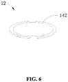
- a photographing device 10 of the embodiments of the present disclosure includes a camera module assembly 11, a glass 12, a temperature sensor 13, a heating element 14, and a controller 15.
- the heating element 14 is disposed on the glass 12.
- the glass 12 is disposed external to the camera module assembly 11 to protect the camera module assembly 11.
- the temperature sensor 13 is configured to detect an internal temperature of the photographing device 10.
- the controller 15 is configured to obtain an external temperature and to control the heating element 14 to heat the glass 12 when a difference between the internal temperature and the external temperature reaches a predetermined temperature.
- the photographing device 10 of the embodiments of the present disclosure includes the heating element 14 disposed on the glass 12.
- the glass 12 may be heated through the heating element 14, to avoid fogging of the photographing device 10.
- the internal temperature of the photographing device 10 may be higher than the external temperature.
- Water molecules inside the photographing device 10 may be condensed when touching the low-temperature glass 12.
- Fogy shaped water droplets may be formed on the internal surface of glass 12 adjacent the interior of the photographing device 10.
- the photographing device 10 of the embodiments of the present disclosure adds a function of heating the glass 12.
- the glass 12 may be heated through the heating element 14, to reduce the temperature difference between the glass 12 and the interior of the photographing device 10, thereby completely solving the fogging issue of the photographing device 10.
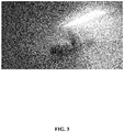
- FIG. 3 is a schematic illustration of the photographing effect of a conventional photographing device 10 implemented in a work environment having a relatively large difference.
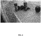
- FIG. 4 is a schematic illustration of the photographing effect of the photographing device 10 of the embodiments of the present disclosure which has a heating function added for the glass 12, when implemented in a work environment having a relatively large difference.
- the photographing device of the embodiments of the present disclosure does not experience fogging phenomenon, and the photographing effect is clear.
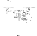
- the photographing device 10 of the embodiments of the present disclosure may be implemented for the aerial photography of a UAV 100 (as shown in FIG. 5 ).
- the glass 12 is disposed external to the camera module assembly 11, to avoid dust and water from entering into the camera module assembly 11, and can avoid damages to the camera module assembly 11 by external objects.
- the temperature sensor 13 is disposed inside the photographing device 10, and is configured to detect an internal temperature of the photographing device 10. Specifically, the temperature sensor 13 may be disposed on the glass 12, such as a side of the glass 12 adjacent the interior of the imaging device 10, or may be disposed inside the camera module assembly 11. The detailed location of the temperature sensor 13 is not limited.
- the controller 15 and the heating element 14 are connected. The controller 15 may obtain the external temperature and may control the heating element 14 to heat the glass 12 when a difference between the internal temperature and the external temperature reaches a predetermined temperature.
- the controller 15 may obtain the external temperature through the following methods: the controller 15 obtains the external temperature detected by the temperature sensor disposed external to the photographing device 10; or the controller 15 communicates or links with other devices to obtain the external temperature; or the photographing device 10 is carried on a gimbal 30 of the UAV 100, and the controller 15 obtains the external temperature from the main controller of the UAV 100.
- the location of the controller 15 may be configured on the glass 12, such as a side of the glass 12 adjacent the interior of the photographing device 10, or may be configured inside the camera module assembly 11. The detailed location of the controller 15 is not limited.
- the camera module assembly 11 includes a circuit board 112, an imaging sensor 114 loaded on the circuit board 112, and a lens module assembly 116 loaded on the circuit board 112.
- the imaging sensor 114 is received in the lens module assembly 116.
- the imaging sensor 114 may be a Charge Coupled Device ("CCD”) or a Complementary Metal Oxide Semiconductor (“CMOS”).
- the circuit board 112 may be a printed circuit board (“PCB”), a flexible circuit board or a soft and hard composite board.
- the imaging sensor 114 is glued to the surface of the circuit board 112.
- the imaging sensor 114 is electrically connected with the circuit board 112 through wires, or is electrically connected with the circuit board 112 through flip chip manner, internal pin bonding, tape automatic bonding, flip bonding packaging or heat press connection method.
- the heating element 14 includes a resistor 142.
- the resistor 142 is electrically connected with the circuit board 112. The heating element 14 heats the glass 12 through supplying a current to the resistor 142 to generate heat to heat the glass 12.
- the controller 15 controls the circuit board 112 to supply a current to the resistor 142, to use the heat generated by the current flowing through the resistor 142 to heat the glass 12.
- a predetermined temperature e.g. 10°C
- the controller 15 controls the circuit board 112 to supply a current to the resistor 142, to use the heat generated by the current flowing through the resistor 142 to heat the glass 12.
- the difference between the internal temperature and the external temperature reaches the predetermined temperature, the larger the difference between the internal temperature and the external temperature, the larger the current supplied to the resistor 142 by the circuit board 112 under control of the controller 15, to realize rapid de-fogging.
- the difference between the internal temperature and the external temperature reaches the predetermined temperature, the larger the difference between the internal temperature and the external temperature, the longer the time the current is supplied to the resistor 142 by the circuit board 112 under control of the controller 15, to maintain the long term constant temperature of the glass 12.
- the resistor 142 is disposed at an external surface of the glass 12; or the resistor 142 is disposed inside the glass 12.
- the resistor 142 disposed at the external surface of the glass 12 may include: the resistor 142 is disposed on a surface (a first external surface 122) of the glass 12 adjacent an interior of the photographing device 10; or the resistor 142 is disposed on a surface (a second external surface 124) of the glass 12 adjacent an exterior of the photographing device 10; or resistors 142 are disposed on both the surface (the first external surface 122) of the glass adjacent the interior of the photographing device 10 and on the surface (the second external surface 124) of the glass adjacent the exterior.
- the resistor 142 is disposed on the surface of the glass 12 adjacent the interior of the photographing device 10. As such, it is convenient for the circuit board 112 to supply a current to the resistor 142, and can function to protect the resistor 142.
- the resistor 142 being disposed inside the glass 12 includes: the resistor 142 is embedded inside the glass 12, and is at a predetermined distance with the first external surface 122 and the second external surface 124; or, the first external surface 122 is provided with a groove, the resistor 142 is embedded within the groove of the first external surface 122 of the glass 12; or, the second external surface 124 is provided with a groove, the resistor 142 is embedded within the groove of the second external surface 124 of the glass 12; or both the first external surface 122 and the second external surface 124 are provided with grooves, and resistors 142 are embedded within the grooves of the first external surface 122 and the second external surface 124 of the glass 12.
- the resistor 142 is embedded inside the glass 12, to realize uniform heating of the glass 12.
- the resistor 142 when the resistor 142 is disposed at the external surface of the glass 12 or is disposed inside the glass 12, preferably, the resistor 142 is disposed at an outer periphery of the glass 12, to avoid the resistor 142 blocking the light, which may affect the photographing effect of the photographing device 10.
- the heating element 14 includes a conductive coating 144.
- the conductive coating 144 is electrically connected with the circuit board 112.
- the heating element 14 heating the glass 12 is realized by heating the glass 12 using heat generated by supplying a current through the conductive coating 144.
- the conductive coating 144 is formed by well distributed nano conductive graphite coated particles.
- the conductive coating 144 has excellent static conductivity performance and cover protection performance.
- the controller 15 controls the circuit board 112 to supply a current to the conductive coating 144, thereby using the heat generated by supplying the current through the conductive coating 144 to heat the glass 12.
- the difference between the internal temperature and the external temperature reaches the predetermined temperature, the larger the difference between the internal temperature and the external temperature, the larger the current supplied to the conductive coating 144 by the circuit board 112 under the control of the controller 15, to realize rapid de-fogging.
- the difference between the internal temperature and the external temperature reaches the predetermined temperature, the larger the difference between the internal temperature and the external temperature, the longer the time the current is supplied to the conductive coating 144 by the circuit board 112 under the control of the controller 15, to maintain a long term constant temperature of the glass 12.
- the photographing device 10 when manufacturing the photographing device 10, by changing the resistance of the conductive coating 144, the photographing device 10 can be used for work environments having different temperature differences. For example, when the photographing device 10 needs to operate in a work environment having a relatively large temperature difference, the resistance of the conductive coating 144 can be made relatively large, to better realize the de-fogging function. When the photographing device 10 needs to operate in a work environment having a relatively small temperature difference, the resistance of the conductive coating 144 can be made relatively small. It should be noted that the temperature difference being relatively large and the temperature difference being relatively small discussed herein refers to the situation where the difference between the internal temperature and the external temperature may reach the predetermined temperature. Where, changing the resistance of the conductive coating 144 may be realized through methods such as changing the resistivity of the conductive coating 144.
- the conductive coating 144 is disposed on an external surface of the glass 12.
- the conductive coating 144 being disposed on the external surface of the glass 12 includes: the conductive coating 144 is disposed on a surface (the first external surface 122) of the glass 12 adjacent the interior of the photographing device 10; or the conductive coating 144 is disposed on a surface (the second external surface 124) of the glass 12 adjacent the photographing device 10; or conductive coatings 144 are disposed on both the surface (first external surface 122) of the glass 12 adjacent the interior of the photographing device 10 and the surface (second external surface 124) of the glass 12 adjacent the exterior.
- the conductive coating 144 is disposed on a surface of the glass 12 adjacent the interior of the photographing device 10. As such, it is convenient for the circuit board 112 to supply the current to the resistor 142, and to function to protect the conductive coating 144.
- the conductive coating 144 is in a transparent state.
- the photographing effect of the photographing device 10 is not affected.
- the heating element 14 may include the resistor 142 and the conductive coating 144.
- the resistor 142 is disposed inside the glass 12.
- the conductive coating 144 is disposed on the glass 12.
- the conductive coating 144 and the circuit board 112 are electrically connected.
- the resistor 142 is electrically connected with the circuit board 112 through the conductive coating 144.
- the heating element 14 heating the glass 12 is realized by heating the glass 12 using heat generated by supplying the current to the resistor 142 and the conductive coating 144.
- the resistor 142 and the conductive coating 144 may be used in combination.
- the conductive coating 144 may be disposed on the external surface of the glass 12, and the resistor 142 is disposed inside the glass 12.
- the conductive coating 144 is electrically connected with the resistor 142.
- the controller 15 controls the circuit board 112 to supply a current to the conductive coating 144, such that the resistor 142 is supplied with a current, thereby heating the glass 12 using the heat generated by supplying the current to the conductive coating 144 and the resistor 142.
- the situation of heating the glass 12 through the heat generated by supplying the current to the resistor 142 and the conductive coating 144 is a combination of the method of heating the glass 12 using heat generated by supplying a current to the resistor 142 and the method of heating the glass 12 using heat generated by supplying a current to the conductive coating 144, which are not described in detail here.
- the photographing device 10 may also include a front cover 16.
- the front cover 16 covers the camera module assembly 11.
- the glass 12 seals an outer side of the front cover 16 that is away from the camera module assembly 11 through a UV curable glue.
- avoiding fogging of the photographing device 10 may also be realized by reducing water content entering the interior of the photographing device 10. It can be understood, when there is fewer water molecules inside the photographing device 10, even if the difference between the internal temperature and the external temperature reaches the predetermined temperature, fogging may not occur easily to the photographing device 10.
- the photographing device 10 may also include the front cover 16 and a dust-proof cotton 17.
- the front cover 16 covers the camera module assembly 11.
- the dust-proof cotton 17 is disposed between the front cover 16 and the camera module assembly 11.
- the material of the dust-proof cotton 17 can use synthetic fiber, non-woven fabric, or glass fiber, etc.
- the photographing device 10 may also include the front cover 16, a back cover 18, and a sealing glue 19.
- the front cover 16 and the back cover 18 may couple together to form a receiving space 162.
- the camera module assembly 11 is received in the receiving space 162.
- the sealing glue 19 is disposed between the back cover 18 and the circuit board 112.
- the sealing glue 19 may use a silica gel.
- the photographing device 10 may also include the front cover 16, the back cover 18, and a hygroscopic material 20.
- the front cover 16 and the back cover 18 couple together to form the receiving space 162.
- the camera module assembly 11 is received in the receiving space 162.
- the hygroscopic material 20 is disposed inside the receiving space 162.
- the hygroscopic material 20 is configured to remove the water content from the interior of the photographing device 10.
- the material of the hygroscopic material 20 can use fiber, silicon dioxide, calcium oxide, calcium chloride, activated carbon, etc.
- the UAV 100 of the embodiments of the present disclosure includes the photographing device 10 and the gimbal 30 of any of the above-described embodiments.
- the photographing device 10 is disposed on the gimbal 30.
- the gimbal 30 is configured to stabilize the photographing device 10.
- the photographing device 10 of the embodiments of the present disclosure can be used in the UAV 100 of the embodiments of the present disclosure.
- the heating element 14 is disposed on the glass 12.
- the glass 12 is heated through the heating element 14, to prevent fogging from occurring to the photographing device 10.
- references to the reference terms “an embodiment,” “some embodiments,” “some illustrative embodiments,” “example,” “specific example,” or “some examples” mean that the specific feature, structure, material or characteristic described with reference to the embodiment or example are included in at least one of the embodiments or examples of the present disclosure.
- illustrative expression of the above terms does not necessarily indicate the same embodiments or examples.
- the described specific feature, structure, material or characteristic may be combined in a suitable matter in any one or multiple embodiments or examples.
- the logic and/or steps shown in the flow chart or otherwise described in other manners, for example, may be regarded as a fixed-order list of executable instructions for realizing the logic functions, may be specifically implemented in any computer-readable medium, for use by the instruction executing system, device, or apparatus (e.g., a computer-based system, a system including a processing module, or other system that can retrieve and execute instructions from the instruction executing system, device, or apparatus), or for use in combination with the instruction executing system, device, or apparatus.
- "computer-readable medium” may be any device that includes, stores, communicates, broadcasts or transmits programs to be used by an instruction executing system, device, or apparatus, or to be used in combination with such instruction executing system, device, or apparatus.
- the computer-readable medium includes the following: an electrical connection portion (control method) having one or multiple wires, a portable computer disk (magnetic device), a random access memory (“RAM”), a read only memory (“ROM”), an erasable programmable read only memory (“EPROM” or flash memory), a fiber optic device, and an optic compact disk read only memory (“CDROM”).
- the computer-readable medium may even be paper or any other suitable medium on which programs can be printed, because, for example, optical scanning may be performed through the paper or other medium, and editing, analysis or when necessary other suitable manner may be used to process to electronically obtain the programs, which may be stored in the computer memory.
- the program may be stored in a computer-readable storage medium. When executed, the program includes one of the steps of the embodiments or their combination.
- various functional units of the various embodiments of the present disclosure can be integrated in one processing module, or may physically exist as individual units, or two or more than two units can be integrated in one module.
- the above integrated module can be realized in the form of hardware, or can be realized in the form of software functional module.
- the integrated module if realized I the form of software functional module and sold or used as independent product, can also be stored in a computer-readable storage medium.
- the storage medium mentioned above can be a read only storage device, a magnetic disk, or an optical disk, etc.
Landscapes
- Engineering & Computer Science (AREA)
- Aviation & Aerospace Engineering (AREA)
- Multimedia (AREA)
- Signal Processing (AREA)
- Physics & Mathematics (AREA)
- Microelectronics & Electronic Packaging (AREA)
- Mechanical Engineering (AREA)
- Remote Sensing (AREA)
- General Physics & Mathematics (AREA)
- Electromagnetism (AREA)
- Studio Devices (AREA)
Applications Claiming Priority (1)
| Application Number | Priority Date | Filing Date | Title |
|---|---|---|---|
| PCT/CN2017/095313 WO2019023897A1 (zh) | 2017-07-31 | 2017-07-31 | 拍摄设备和无人机 |
Publications (2)
| Publication Number | Publication Date |
|---|---|
| EP3663224A1 true EP3663224A1 (de) | 2020-06-10 |
| EP3663224A4 EP3663224A4 (de) | 2021-04-14 |
Family
ID=63489839
Family Applications (1)
| Application Number | Title | Priority Date | Filing Date |
|---|---|---|---|
| EP17920223.9A Withdrawn EP3663224A4 (de) | 2017-07-31 | 2017-07-31 | Fotografievorrichtung und unbemanntes luftfahrzeug |
Country Status (4)
| Country | Link |
|---|---|
| US (2) | US11119390B2 (de) |
| EP (1) | EP3663224A4 (de) |
| CN (1) | CN108541372A (de) |
| WO (1) | WO2019023897A1 (de) |
Families Citing this family (13)
| Publication number | Priority date | Publication date | Assignee | Title |
|---|---|---|---|---|
| JP6723194B2 (ja) * | 2017-04-26 | 2020-07-15 | 株式会社東海理化電機製作所 | 撮像装置 |
| FR3079627B1 (fr) * | 2018-03-29 | 2021-07-09 | Delphi Tech Llc | Dispositif optique pour vehicule comprenant un element de chauffage |
| JP7293969B2 (ja) * | 2018-10-25 | 2023-06-20 | 株式会社デンソー | ヒータ装置 |
| JP6690105B1 (ja) * | 2018-10-31 | 2020-04-28 | エスゼット ディージェイアイ テクノロジー カンパニー リミテッドSz Dji Technology Co.,Ltd | 制御装置、撮像装置、システム、制御方法、及びプログラム |
| US11453366B2 (en) * | 2018-11-06 | 2022-09-27 | Motherson Innovations Company Limited | Heatable device for use with a vehicle-mounted image acquisition unit |
| CN111812919B (zh) * | 2020-04-30 | 2022-07-05 | 广东弘景光电科技股份有限公司 | 外置式雨滴检测自动加热去雨滴除水汽摄像模组 |
| CN111818245B (zh) * | 2020-07-03 | 2021-05-04 | 江苏集萃智能光电系统研究所有限公司 | 用于户外复杂环境的视觉传感器光学优化装置及校正方法 |
| US11474417B2 (en) | 2020-08-07 | 2022-10-18 | Lineage Logistics, LLC | Lens heater assembly for camera |
| CN112009710A (zh) * | 2020-09-23 | 2020-12-01 | 袁兴平 | 一种无人机摄像头新型云台结构 |
| CN112731743B (zh) * | 2020-12-30 | 2022-06-28 | 宜宾市极米光电有限公司 | 一种投影仪和除水雾方法 |
| JP2022143257A (ja) * | 2021-03-17 | 2022-10-03 | i-PRO株式会社 | 監視カメラ |
| EP4334207A1 (de) * | 2021-05-07 | 2024-03-13 | Flightwave Aerospace Systems | Leichte hochauflösende kameranutzlast für kleine luftfahrzeuge |
| CN114363561A (zh) * | 2021-12-03 | 2022-04-15 | 中国科学院西北生态环境资源研究院 | 一种基于远程遥感的高寒山地草原退化程度的检测系统 |
Family Cites Families (22)
| Publication number | Priority date | Publication date | Assignee | Title |
|---|---|---|---|---|
| US3421721A (en) * | 1968-02-06 | 1969-01-14 | Mark Hurd Aerial Surveys Inc | Aircraft camera mounting |
| JP2004258293A (ja) * | 2003-02-26 | 2004-09-16 | Japan Aviation Electronics Industry Ltd | スタビライザ付カメラ |
| WO2005060312A1 (ja) * | 2003-12-16 | 2005-06-30 | Murakami Corporation | 発熱素子 |
| FR2917939B1 (fr) * | 2007-06-22 | 2009-09-04 | Airbus France Sas | Systeme de degivrage ou de desembuage d'un instrument optique et dispositif d'acquisition d'images equipe d'un tel systeme. |
| JPWO2009119478A1 (ja) * | 2008-03-27 | 2011-07-21 | コニカミノルタオプト株式会社 | 光学素子集合体、撮像モジュール及び電子機器の製造方法 |
| DE102008033316A1 (de) * | 2008-07-16 | 2010-01-21 | Siemens Aktiengesellschaft | Heizvorrichtung zur Beheizung einer Glasfläche, insbesondere eines Schutzglases einer Außenkamera |
| WO2014058511A2 (en) * | 2012-08-01 | 2014-04-17 | Bye Uas, Inc. | Small uas with high definition video |
| CN203299507U (zh) * | 2013-05-10 | 2013-11-20 | 北京宇航系统工程研究所 | 一种适用于低温环境下的摄像装置 |
| US9461706B1 (en) * | 2015-07-31 | 2016-10-04 | At&T Intellectual Property I, Lp | Method and apparatus for exchanging communication signals |
| EP3281397B1 (de) * | 2015-04-08 | 2019-10-16 | Illinois Tool Works Inc. | Kameraheizelement für erweitertes fahrerassistenzsystem |
| CN106488089A (zh) * | 2015-09-01 | 2017-03-08 | 上海雷卓网络科技有限公司 | 防雾摄像机 |
| CN106547284B (zh) * | 2015-09-22 | 2019-01-18 | 华为数字技术(苏州)有限公司 | 除湿方法及摄像机 |
| CN106559607A (zh) * | 2015-09-24 | 2017-04-05 | 湖北金视通信息技术有限公司 | 一种防尘、防雾摄像装置 |
| CN205193411U (zh) * | 2015-11-24 | 2016-04-27 | 重庆丘比盾科技有限公司 | 带加热装置的摄像头 |
| US11095129B2 (en) * | 2016-02-12 | 2021-08-17 | Capacitor Sciences Incorporated | Capacitor based power system and unmanned vehicle with the capacitor based power system thereof |
| US11174021B2 (en) * | 2016-03-24 | 2021-11-16 | Flir Detection, Inc. | Persistent aerial reconnaissance and communication system |
| US11977395B2 (en) * | 2016-03-24 | 2024-05-07 | Teledyne Flir Defense, Inc. | Persistent aerial communication and control system |
| CN106125464A (zh) * | 2016-08-23 | 2016-11-16 | 苏州国创电子科技有限公司 | 一种镜头及应用该镜头的摄像头 |
| KR102612029B1 (ko) * | 2017-01-03 | 2023-12-11 | 삼성전자 주식회사 | 무인 비행 장치 키트 및 시스템 |
| US10099785B1 (en) * | 2017-07-25 | 2018-10-16 | Oswaldo Gonzalez | Drone with ring assembly |
| US10836508B2 (en) * | 2018-02-16 | 2020-11-17 | Jeffrey Paul Overall | Camera drone |
| US10839492B2 (en) * | 2018-05-23 | 2020-11-17 | International Business Machines Corporation | Selectively redacting unrelated objects from images of a group captured within a coverage area |
-
2017
- 2017-07-31 CN CN201780005215.4A patent/CN108541372A/zh active Pending
- 2017-07-31 WO PCT/CN2017/095313 patent/WO2019023897A1/zh unknown
- 2017-07-31 EP EP17920223.9A patent/EP3663224A4/de not_active Withdrawn
-
2020
- 2020-01-21 US US16/747,785 patent/US11119390B2/en active Active
-
2021
- 2021-09-13 US US17/473,684 patent/US20210405510A1/en not_active Abandoned
Also Published As
| Publication number | Publication date |
|---|---|
| WO2019023897A1 (zh) | 2019-02-07 |
| CN108541372A (zh) | 2018-09-14 |
| US11119390B2 (en) | 2021-09-14 |
| EP3663224A4 (de) | 2021-04-14 |
| US20200159090A1 (en) | 2020-05-21 |
| US20210405510A1 (en) | 2021-12-30 |
Similar Documents
| Publication | Publication Date | Title |
|---|---|---|
| US11119390B2 (en) | Photographing device and unmanned aerial vehicle | |
| US11480755B2 (en) | Imaging lens module and electronic device | |
| CN107690594B (zh) | 透镜镜筒和包括该透镜镜筒的相机模块 | |
| CN113630534B (zh) | 相机模块及车辆 | |
| KR102556516B1 (ko) | 카메라 모듈 | |
| KR101774091B1 (ko) | 적외선 카메라 시스템 구조 | |
| CN106664358B (zh) | 摄像装置、光学设备、电子设备、车辆以及摄像装置的制造方法 | |
| US20170187931A1 (en) | Vehicle-mounted camera | |
| EP3477352B1 (de) | Kameramodul mit fixfokus | |
| US11082640B2 (en) | Infrared camera | |
| US9235023B2 (en) | Variable lens sleeve spacer | |
| EP3244602B1 (de) | Bildaufnahmevorrichtung, wie etwa netzwerkkamera, und bildüberwachungssystem | |
| CN108061955A (zh) | 塑胶光学透镜组、成像镜头模块及电子装置 | |
| US20120315953A1 (en) | Enclosure for image capture systems with focusing capabilities | |
| US10666880B2 (en) | Infrared camera assembly for a vehicle | |
| CN106851061B (zh) | 图像采集设备 | |
| US20160104738A1 (en) | Image sensing device with interconnect layer gap and related methods | |
| CN106603898B (zh) | 多拍摄角度的一体式摄像头模组 | |
| US20220163751A1 (en) | Heating device and camera module | |
| US9349903B2 (en) | Image sensing module and method of manufacturing the same | |
| JP7257324B2 (ja) | 液体レンズ及びこれを含むカメラモジュール及び光学機器 | |
| US20170052385A1 (en) | Lens focusing method and optical module | |
| KR20180006045A (ko) | 렌즈 어셈블리 및 이를 포함하는 카메라 모듈 | |
| KR20200014971A (ko) | 카메라 모듈 | |
| KR20200114051A (ko) | 카메라 장치의 습도 조절기 및 카메라 장치 |
Legal Events
| Date | Code | Title | Description |
|---|---|---|---|
| STAA | Information on the status of an ep patent application or granted ep patent |
Free format text: STATUS: THE INTERNATIONAL PUBLICATION HAS BEEN MADE |
|
| PUAI | Public reference made under article 153(3) epc to a published international application that has entered the european phase |
Free format text: ORIGINAL CODE: 0009012 |
|
| STAA | Information on the status of an ep patent application or granted ep patent |
Free format text: STATUS: REQUEST FOR EXAMINATION WAS MADE |
|
| 17P | Request for examination filed |
Effective date: 20191227 |
|
| AK | Designated contracting states |
Kind code of ref document: A1 Designated state(s): AL AT BE BG CH CY CZ DE DK EE ES FI FR GB GR HR HU IE IS IT LI LT LU LV MC MK MT NL NO PL PT RO RS SE SI SK SM TR |
|
| AX | Request for extension of the european patent |
Extension state: BA ME |
|
| DAV | Request for validation of the european patent (deleted) | ||
| DAX | Request for extension of the european patent (deleted) | ||
| A4 | Supplementary search report drawn up and despatched |
Effective date: 20210312 |
|
| RIC1 | Information provided on ipc code assigned before grant |
Ipc: B65D 47/08 20060101AFI20210308BHEP Ipc: G03B 17/02 20210101ALI20210308BHEP |
|
| STAA | Information on the status of an ep patent application or granted ep patent |
Free format text: STATUS: THE APPLICATION IS DEEMED TO BE WITHDRAWN |
|
| 18D | Application deemed to be withdrawn |
Effective date: 20211012 |