EP3662842A1 - Endobronchiale ultraschallbildgebung - Google Patents
Endobronchiale ultraschallbildgebung Download PDFInfo
- Publication number
- EP3662842A1 EP3662842A1 EP19209052.0A EP19209052A EP3662842A1 EP 3662842 A1 EP3662842 A1 EP 3662842A1 EP 19209052 A EP19209052 A EP 19209052A EP 3662842 A1 EP3662842 A1 EP 3662842A1
- Authority
- EP
- European Patent Office
- Prior art keywords
- ultrasound transducer
- bronchoscope
- transducer array
- insertion tube
- distal tip
- Prior art date
- Legal status (The legal status is an assumption and is not a legal conclusion. Google has not performed a legal analysis and makes no representation as to the accuracy of the status listed.)
- Granted
Links
Images


Classifications
-
- A—HUMAN NECESSITIES
- A61—MEDICAL OR VETERINARY SCIENCE; HYGIENE
- A61B—DIAGNOSIS; SURGERY; IDENTIFICATION
- A61B8/00—Diagnosis using ultrasonic, sonic or infrasonic waves
- A61B8/12—Diagnosis using ultrasonic, sonic or infrasonic waves in body cavities or body tracts, e.g. by using catheters
-
- A—HUMAN NECESSITIES
- A61—MEDICAL OR VETERINARY SCIENCE; HYGIENE
- A61B—DIAGNOSIS; SURGERY; IDENTIFICATION
- A61B1/00—Instruments for performing medical examinations of the interior of cavities or tubes of the body by visual or photographical inspection, e.g. endoscopes; Illuminating arrangements therefor
- A61B1/267—Instruments for performing medical examinations of the interior of cavities or tubes of the body by visual or photographical inspection, e.g. endoscopes; Illuminating arrangements therefor for the respiratory tract, e.g. laryngoscopes, bronchoscopes
- A61B1/2676—Bronchoscopes
-
- A—HUMAN NECESSITIES
- A61—MEDICAL OR VETERINARY SCIENCE; HYGIENE
- A61B—DIAGNOSIS; SURGERY; IDENTIFICATION
- A61B1/00—Instruments for performing medical examinations of the interior of cavities or tubes of the body by visual or photographical inspection, e.g. endoscopes; Illuminating arrangements therefor
- A61B1/00064—Constructional details of the endoscope body
- A61B1/00066—Proximal part of endoscope body, e.g. handles
-
- A—HUMAN NECESSITIES
- A61—MEDICAL OR VETERINARY SCIENCE; HYGIENE
- A61B—DIAGNOSIS; SURGERY; IDENTIFICATION
- A61B1/00—Instruments for performing medical examinations of the interior of cavities or tubes of the body by visual or photographical inspection, e.g. endoscopes; Illuminating arrangements therefor
- A61B1/00112—Connection or coupling means
- A61B1/00114—Electrical cables in or with an endoscope
-
- A—HUMAN NECESSITIES
- A61—MEDICAL OR VETERINARY SCIENCE; HYGIENE
- A61B—DIAGNOSIS; SURGERY; IDENTIFICATION
- A61B1/00—Instruments for performing medical examinations of the interior of cavities or tubes of the body by visual or photographical inspection, e.g. endoscopes; Illuminating arrangements therefor
- A61B1/04—Instruments for performing medical examinations of the interior of cavities or tubes of the body by visual or photographical inspection, e.g. endoscopes; Illuminating arrangements therefor combined with photographic or television appliances
- A61B1/05—Instruments for performing medical examinations of the interior of cavities or tubes of the body by visual or photographical inspection, e.g. endoscopes; Illuminating arrangements therefor combined with photographic or television appliances characterised by the image sensor, e.g. camera, being in the distal end portion
-
- A—HUMAN NECESSITIES
- A61—MEDICAL OR VETERINARY SCIENCE; HYGIENE
- A61B—DIAGNOSIS; SURGERY; IDENTIFICATION
- A61B5/00—Measuring for diagnostic purposes; Identification of persons
- A61B5/0033—Features or image-related aspects of imaging apparatus, e.g. for MRI, optical tomography or impedance tomography apparatus; Arrangements of imaging apparatus in a room
-
- A—HUMAN NECESSITIES
- A61—MEDICAL OR VETERINARY SCIENCE; HYGIENE
- A61B—DIAGNOSIS; SURGERY; IDENTIFICATION
- A61B5/00—Measuring for diagnostic purposes; Identification of persons
- A61B5/68—Arrangements of detecting, measuring or recording means, e.g. sensors, in relation to patient
- A61B5/6846—Arrangements of detecting, measuring or recording means, e.g. sensors, in relation to patient specially adapted to be brought in contact with an internal body part, i.e. invasive
- A61B5/6847—Arrangements of detecting, measuring or recording means, e.g. sensors, in relation to patient specially adapted to be brought in contact with an internal body part, i.e. invasive mounted on an invasive device
- A61B5/6852—Catheters
- A61B5/6853—Catheters with a balloon
-
- A—HUMAN NECESSITIES
- A61—MEDICAL OR VETERINARY SCIENCE; HYGIENE
- A61B—DIAGNOSIS; SURGERY; IDENTIFICATION
- A61B8/00—Diagnosis using ultrasonic, sonic or infrasonic waves
- A61B8/44—Constructional features of the ultrasonic, sonic or infrasonic diagnostic device
- A61B8/4483—Constructional features of the ultrasonic, sonic or infrasonic diagnostic device characterised by features of the ultrasound transducer
-
- A—HUMAN NECESSITIES
- A61—MEDICAL OR VETERINARY SCIENCE; HYGIENE
- A61B—DIAGNOSIS; SURGERY; IDENTIFICATION
- A61B8/00—Diagnosis using ultrasonic, sonic or infrasonic waves
- A61B8/56—Details of data transmission or power supply
-
- A—HUMAN NECESSITIES
- A61—MEDICAL OR VETERINARY SCIENCE; HYGIENE
- A61B—DIAGNOSIS; SURGERY; IDENTIFICATION
- A61B2562/00—Details of sensors; Constructional details of sensor housings or probes; Accessories for sensors
- A61B2562/02—Details of sensors specially adapted for in-vivo measurements
- A61B2562/0204—Acoustic sensors
Definitions
- EBUS endobronchial ultrasound
- TBNA transbronchial needle aspiration
- EBUS bronchoscopes are reusable. Healthcare facilities reprocess EBUS bronchoscopes between uses in different patients to minimize infection risks.
- a reliable, high-quality reprocessing program requires an infrastructure that involves administration, documentation, inventory control, physical facility maintenance, education, training, risk assessment, and quality assurance.
- Implementations described herein relate to an endobronchial ultrasound (EBUS) bronchoscope that can employed as a single-use (e.g., disposable) device.
- the EBUS bronchoscope may be used, for example, to image bronchial lymph nodes for lung cancer staging and to guide transbronchial needle aspiration (TBNA).
- the EBUS bronchoscope includes a microelectromechanical system (MEMS)-based ultrasound transducer.
- MEMS microelectromechanical system
- the transducer is curved to enable imaging a wider view, compared to a flat array.
- the transducer is integrated with analog and digital electronics installed within a distal tip of the EBUS bronchoscope.
- the arrangement requires fewer wires (e.g., compared to a conventional EBUS bronchoscope) and a correspondingly smaller diameter lumen extending through an insertion tube.
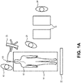
- Fig. 1A illustrates a top view of an exemplary use of EBUS technology by an operator 10 (e.g., a pulmonologist or pulmonary interventionist) for evaluation of the lungs of a patient 12.
- An interventional suite may include a patient table 14, one or more portable carts 16, a console 20, a display 22, and an EBUS bronchoscope 100.
- the patient 12 lies supine upon the patient table 14.
- the operator 10 is generally at one end of the patient table 14 toward the head of the patient 12.
- One or more assistants 24 may be present.
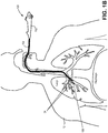
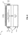
- FIG. 1B is a cross-sectional view of the upper body of the patient 12 with a side view of EBUS bronchoscope 100 delivered to the bronchus of the patient 12.
- EBUS bronchoscope 100 includes a handle 102 connected to an insertion tube 104 that is inserted into the patient and directed to a region of interest.
- a distal tip 106 of the EBUS bronchoscope 100 may be positioned in proximity to one or more bronchial lymph nodes 24.
- Fig. 2 is a side view of EBUS bronchoscope 100, including handle 102, insertion tube 104, and distal tip 106.
- Insertion tube 104 may include a proximal section 202 that connects to handle 102 and a distal section 204 between proximal section 202 and distal tip 106.
- Handle 102 includes a working channel entry port 206, an injection port 208, and a suction port 212.
- Working channel entry port 206 may be used for inserting fluids or tools (e.g., a biopsy needle, etc.) into a working channel (e.g., working channel 302, Fig. 3 ) extending through insertion tube 104 and exiting near distal tip 106.
- a working channel e.g., working channel 302, Fig. 3
- Injection port 208 may be used to insert or extract fluid through a lumen (e.g., inflation lumen 408, Fig. 4 ) extending through insertion tube 104 to distal tip 106.
- Suction port 212 may also feed into the working channel (e.g., working channel 302) to provide suction through the working channel.
- Handle 102 also includes a series of controls, such as a flexion/extension lever 210, a suction button 214, and/or one or more image/video controls 216.
- the flexion/extension lever 210 controls wires within insertion tube 104 for steering distal tip 106 during insertion to a patient.
- the suction button 214 controls a valve adjacent to the suction port for purposes of controlling suction when suction port 212 is connected to a suction device.
- the image/video control(s) 216 can be used to take still and video images at distal tip 106 throughout the procedure.
- distal tip 106 includes an ultrasound transducer that enables visualization of the structure of bronchial walls and surrounding tissues (e.g., including bronchial lymph nodes 24).
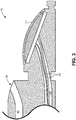
- Fig. 3 is cross-sectional side view of distal tip 106, according to an implementation described herein.
- Fig. 4 is a cross-sectional end view of distal section 204 of insertion tube 104, shown along section A-A of Fig. 2 .
- Fig. 5 is a side view of view distal tip 106, shown with a partially inflated balloon 502 installed and a biopsy needle 504 extending from working channel exit port 306.
- insertion tube 104 includes working channel lumen 302, ultrasound (US) imaging core lumen 304, two flexion/extension cable lumens 406, and an inflation lumen 408.
- US ultrasound
- EBUS bronchoscope 100 is designed to enable delivery of the distal tip 106 to the bronchi (e.g., of patient 12), with good push-ability, torque-ability, and steer-ability to enable an operator to easily manipulate distal tip 106 to a desired location and orientation.
- Each of working channel lumen 302, US imaging core lumen 304, and inflation lumen 408 may extend from handle 102 to the general area of distal tip 106 along the axial length of insertion tube 104.
- Flexion/extension cable lumens 406 may extend substantially along the axial length of insertion tube 104, but not as far as distal tip 106.
- Working channel lumen 302 may accommodate tools or fluids to perform procedures near distal tip 106.
- Working channel lumen 302 may join or connect with working channel entry port 206 in handle 102 to a working channel exit port 306 near distal tip 106.
- a tool e.g., biopsy needle 504, forceps, etc.
- guidewires that is inserted at working channel entry port 206 may be pushed through working channel lumen 302 and exit through working channel exit port 306 to access a body part of the patient.
- US imaging core lumen 304 may accommodate power and communication wires (referred to herein collectively as cables 308) to enable use of ultrasound transducer assembly 310. US imaging core lumen 304 may permit cables 308 from ultrasound transducer assembly 310 to extend back to handle 102, which may, in turn, connect cables 308 to console 20.
- Transducer assembly 310 may include a MEMS-based ultrasound transducer with integrated analog and/or digital electronics installed at distal tip 106.
- the inclusion of integrated electronics within distal tip 106 minimizes the number of wires required to pass through US imaging core lumen 304, reducing material and assembly costs while allowing for the diameter of US imaging core lumen 304 to be minimized.
- Transducer assembly 310 is described further, for example, in connection with Figs. 6-8 below.
- Flexion/extension cable lumens 406 accommodate cables 404 extending from flexion/extension lever 210 (or another steering control) into distal section 204.
- the cables 404 may be used to steer/direct distal tip 106 of insertion tube 104 in the patient.
- flexion/extension lever 210, flexion/extension cable lumens 406 and cables 404 may be eliminated from EBUS bronchoscope 100, such as when a diameter of insertion tube 104 and distal tip 106 are small enough to be inserted within a working channel of a larger bronchoscope.
- EBUS bronchoscope 100 includes a balloon 502 that may be installed over a portion of distal tip 106, and particularly adjacent to ultrasound transducer assembly 310.
- Balloon 502 may include, for example, a sterile latex balloon that may be inflated when distal tip 106 is within the patient.
- balloon 502 may be inflated with saline solution after insertion into the patient to prevent an air interface with the transducer array of ultrasound transducer assembly 310 during ultrasound scanning.
- Inflation lumen 408 may provide a channel from injection port 208 in handle 102 to an outlet port 508 in distal tip 106.
- Outlet port 508 may be located anywhere within the portion of distal tip 106 that is encased by balloon 502.
- Inflation lumen 408 may provide a path for saline (or other fluid) to be inserted into and extracted from balloon 502.
- a syringe at injection port 208 may be used to insert fluid through inflation lumen to balloon 502.
- EBUS bronchoscope 100 may be provided as single-use (e.g., disposable) device
- EBUS bronchoscope 100 may be provided to practitioners (e.g., by a medical equipment provider) in sterile packaging with balloon 502 pre-installed over distal tip 106, thus reducing clinician preparation time.
- EBUS bronchoscope 100 may be provided with an integrated biopsy needle 540 positioned within working channel lumen 302.
- Fig. 6 is a cross-sectional side view of transducer assembly 310.
- transducer assembly 310 may include curved ultrasound transducer array 602, integrated signal processing electronics 606, and a flexible interconnection 608.
- Transducer array 602 may include multiple MEMS drums 610 mounted on a curved substrate 612.
- each of MEMS drums 610 may include a thin nitride membrane and top aluminum electrode suspended over a cavity.
- drums 610 are capacitive structures that operate under an applied electrostatic field. A signal voltage applied across the membrane varies the membrane tension and causes drums 610 to vibrate and emit ultrasonic waves. Conversely, during reception of ultrasound, an acoustic wave causes the membrane to move, altering the capacitance of the drums 610 and creating an output current.
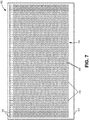
- Fig. 7 is a top view of curved ultrasound transducer array 602.
- one or more MEMS drums 610 may be connected to electrodes 702.
- transducer array 602 may be a MEMS-based ultrasound design, such as a capacitive micromachined ultrasound transducer (CMUT) or piezoelectric micromachined ultrasound transducer (PMUT).
- Transducer array 602 may include multiple elements 704. Each element 704 includes one or more MEMS drums 610 and an electrode 702 which are electrically connected. As shown in the example of Fig.
- an element 704 may include a row of MEMS drums 610 connected to a single electrode 702.
- MEMS drums 610 act as transducer elements that transmit ultrasound energy and receive acoustic reflections or echoes generated by internal structures/tissue within the patient.
- Substrate 612 may be made of silicon, for example.
- the MEMS-based ultrasound transducer described herein may provide for integrated electronics and relatively low cost.
- ultrasound transducer array 602 includes a two-dimensional curved array.
- the curve of ultrasound transducer array 602 is generally convex (e.g., curves outward) relative to the longitudinal axis of insertion tube 104.
- a curved array can provide a wider field of view than a typical flat array, which is important for ultrasound transducers having a limited aperture size.
- the ultrasound transducer may have a nominal center frequency between 5 megaHertz (MHz) and 25 MHz. The nominal center frequency is approximately 7.5 MHz for imaging the major bronchi and may be greater than 10 MHz for imaging the peripheral bronchi.
- the orientation of transducer elements 704 may be stationary with respect to probe distal tip 106 so that a selected anatomical region may be scanned by selectively energizing elements 704 in the array 602.
- Signal-processing electronics 606 may be used to provide transmit-and-receive circuitry and/or beamforming logic for ultrasound transducer array 602 within distal tip 106.
- signal-processing electronics 606 may include an application-specific integrated circuit (ASIC).
- Fig. 8 is a functional block diagram of signal-processing electronics 606. As shown in Fig. 8 , signal-processing electronics 606 may include an analog front end (AFE) 802, a beamformer 804, and connection lines 806. AFE 802 may include transmit-and-receive circuitry for ultrasound transducer array 602.
- AFE analog front end
- AFE 802 may include transmit-and-receive circuitry for ultrasound transducer array 602.
- AFE 802 may include, for example, a processor (e.g., a field-programmable gate array (FPGA), a reduced instruction set computing (RISC) microcontroller, etc.), a digital-to-analog converter (DAC), a transmitter (Tx) 420, a transmit/receive (T/R) switch, a multiplexer/demultiplexer (MUX/DEMUX), time-gain compensation (TGC) circuitry, and an analog-to-digital converter (ADC).
- AFE 802 may adjust the characteristics of ultrasound signals, such as the carrier frequency, acoustic intensity, pulse repeating frequency (PRF), signal bias, gain level, etc., in achieving the optimal performance for US transducer assembly 310.
- Beamformer 804 may provide input to AFE 802 for controlling the phase and relative amplitude of signals to provide directional signal transmission or reception.
- Connection lines 806 may include connections for elements 704 of curved ultrasound transducer array 602 (e.g., corresponding to flexible interconnection 608), as well as power connection, transmit drive signal connections, clock signals, receive signals, and control lines.
- the arrangement of signal-processing electronics 606 as part of transducer assembly 310 within distal tip 106 may reduce the number and/or length of transmission lines typically required for an ultrasound transducer array. A reduction in number of transmission lines can reduce cost of EBUS bronchoscope 100.
- Flexible interconnection 608 may provide wired connections between transducer array 602 and ASIC 606.
- flexible interconnection 608 may include an interconnect platform of high density wiring, such as FLEX-TO-RIGID (F2R) technology.
- Transducer array 602 may be fabricated on silicon wafers, transferred onto polyimide, and partially rendered flexible by means of a two-step backside silicon deep reactive ion etching. This flexibility allows for the transducer array 602 to be wrapped around distal tip 106 of insertion tube 104, for example.
- transducer assembly 910 may include a flat ultrasound transducer array 902 with integrated signal processing electronics 606, and an interconnection 908.
- Transducer array 902 may include multiple MEMS drums 610 mounted on a flat substrate 912.
- Transducer assembly 910 may further include a lens 904 that encapsulates MEMS drums 610.
- Lens 904 may include an encapsulating material for MEMS drums to mechanically focus the array.
- interconnection 908 may be similar to flexible interconnection 608
- interconnection 908 may include a different (e.g., rigid) type of connection between transducer array 902 and signal-processing electronics 606.
- FIG. 10 is an illustration of an ultrasound image of a bronchial lymph node from EBUS bronchoscope 100.
- An image 1002 may be presented on display 22.
- Image 1002 may correspond to an ultrasound field of view, which captures a lymph node 1004.
- Lymph node 1004 is shown with measurements of a long axis 1006 and a short axis 1008.
- Image characteristics that may be useful for detection of lung cancer include lymph node size, shape, margin, echogenicity, and other structural details.
- Exemplary details include whether the lymph node size is less than or greater than one centimeter (along short axis 1008), whether the shape is an oval or a circle, whether the margin is indistinct or distinct, whether the echogenicity is homogenous or inhomogeneous, whether the central hilar structure is present or absent, and whether a coagulation necrosis sign is present or absent.
- Machine learning algorithms such as deep learning convolution neural networks, may be used to automate detection of cancer in bronchial lymph nodes.
- Fig. 11 is an illustration of a cross sectional side view of distal tip 106 of EBUS bronchoscope 100 according to another implementation described herein.
- Fig. 11 illustrates distal tip 106 with a camera module 1102 extending through a camera channel 1104 and out a camera exit port 1106.
- Camera channel 1104 may extend along the axial length of insertion tube 104 back to handle 102 and connect electrically to the console 20.
- Camera exit port 1106 may generally point camera module 1102 to view the same area (i.e., of a patient) that would be interrogated by transducer array 602.
- the views from camera module 1102 and images obtained from transducer assembly 310 may be used in combination to detect and guide insertion of tools (e.g., biopsy needle 504) from working channel lumen 302.
- tools e.g., biopsy needle 504
- EBUS bronchoscope 100 can be used to guide transbronchial needle aspiration (TBNA) for bronchial lymph node biopsy.
- TBNA transbronchial needle aspiration
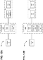
- Figs. 12A and 12B are block diagrams illustrating different arrangements of functional components of an EBUS system 1200 according to implementations described herein. Particularly, Figs. 12A and 12B illustrate different locations for signal processing electronics 606 (e.g., analog front end 802 and beamformer 804) within EBUS system 1200. As shown in Figs. 12A and 12B , EBUS system 1200 may include console 20, EBUS bronchoscope 100, and an interface module 1210. Interface module 1210 may be implemented as separate module, integrated within console 20, integrated within handle 102, distributed among a cable and console 20, distributed among multiple consoles, etc.
- signal processing electronics 606 e.g., analog front end 802 and beamformer 804
- EBUS system 1200 may include console 20, EBUS bronchoscope 100, and an interface module 1210.
- Interface module 1210 may be implemented as separate module, integrated within console 20, integrated within handle 102, distributed among a cable and console 20, distributed among multiple consoles, etc.
- interface module 1210 may include a power supply 1212 and control logic 1214.
- Power supply 1212 may include an internal power supply (e.g., rechargeable battery, replaceable battery, etc.), and/or provide connection to an external power supply (e.g., an outlet, AC or DC power, etc.) for components of EBUS bronchoscope 100.
- Control logic 1214 may provide commands for AFE 802 and beamformer 804 to implement or execute.
- Control logic 1214 may also control application of power from an external power source (e.g., a charger) to one or more components of EBUS bronchoscope 100.
- an external power source e.g., a charger
- EBUS bronchoscope 100 may include analog front end 802 and beamformer 804 (e.g., signal-processing electronics 606 of Fig. 6 ) and transducer array 602.
- analog front end 802, beamformer 804, and transducer array 602 may be included within distal tip 106.
- Analog front end 802 may, for example, perform multiplexing and other signal processing to transmit and receive ultrasound signals.
- Beamformer 804 may, for example, adjust phase, frequency, and/or amplitude modulations for the MEMS drums of transducer array 602.
- EBUS bronchoscope 100 may include analog front end 802 and transducer array 602.
- analog front end 802 and transducer array 602 may be included within distal tip 106.
- beamformer 804 may function similarly as in the configuration of Fig. 12A .
- beamformer 804 may be located in interface module 1210 (e.g., some signal-processing electronics 606 of Fig. 6 are in different physical locations).
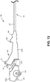
- Fig. 13 is a side view of a portion 1300 of EBUS bronchoscope 100, including handle 1302 (comprising segments 1302a and 1302b) and proximal section 202 of insertion tube 104.
- handle 1302 may be separated into detachably connected segments 1302a and 1302b through use of a coupling 1310.
- handle 1302 may include a linking interface 1320 that allows handle segment 1302b to be attached to handle segment 1302a for a procedure and removed/discarded at the completion of the procedure (e.g., single use of handle segment 1302b and insertion tube 104, with a reusable handle segment 1302a).
- handle segments 1302a and 1302b are located such that working channel entry port 206, injection port 208, and suction port 212 are included within handle segment 1302b, such that all ports, channels, and/or lumens exposed to bodily fluids during a procedure are included in the disposable components of handle segment 1302b and insertion tube 104.
- Linking interface 1320 may include a power cable interface to connect one or more power cables (e.g., cables 308) from imaging core lumen 304 and handle segment 1302b to a power supply (e.g. power supply 1212) accessible in or through handle segment 1302a.
- Linking interface 1320 may also include a communication interface to connect the communication wires (e.g., cables 308) to wires in handle segment 1302a that lead to control logic (e.g., control logic 1214).
- control logic e.g., control logic 1214
- linking interface 1320 may provide additional connections for flexion/extension lever 210 to connect to cables 404 extending from flexion/extension cable lumens 406.
- coupling 1310 may include a mechanical push-on coupling, a threaded coupling, an interference fit coupling, etc.
- an endobronchial ultrasound (EBUS) bronchoscope is configured as a single-use (e.g., disposable) device.
- the bronchoscope includes an insertion tube having a proximal section adjacent the handle and a distal tip.
- An ultrasound transducer assembly is located at or near the distal tip.
- the ultrasound transducer assembly includes an ultrasound transducer array, transmit-and-receive circuitry for the ultrasound transducer array, and a flexible interconnection between the ultrasound transducer array and the transmit-and-receive circuitry.
- the insertion tube further includes an imaging lumen including one or more power cables and one or more communication wires that extend from the ultrasound transducer assembly through the proximal section and a working channel that is separate from the imaging lumen.
- a single-use insertion tube and handle segment may be provided for use with a reusable handle segment.
- a linking interface is provided for removably connecting a disposable handle segment to the reusable handle segment of the bronchoscope.
- the linking interface connects one or more power cables to a power supply and connects one or more communication wires to control logic in the handle.
- systems and methods described herein may be applied to an endoscopic ultrasound procedure in other areas of the body (e.g., for upper gastrointestinal tract or lower gastrointestinal tract). More particularly, a MEMS-based ultrasound transducer may integrated with analog and/or digital electronics installed within a distal tip of an endoscope insertion tube in manner similar to that described above.
- the systems and methods described herein may provide a disposable EBUS bronchoscope, a disposable bronchoscope insertion tube and handle segment, a disposable endoscope, and/or a disposable endoscope insertion tube and handle segment.
- a disposable EBUS bronchoscope By implementing these devices as single-use components, healthcare facilities can avoid the expense, time, and logistics of reprocessing EBUS bronchoscopes and/or endoscopes between uses in different patients.
- the devices may be supplied fully-assembled in sterile packaging so that separate attachment of some other disposable components, such as inflatable balloons and biopsy needles, is not required.
- This logic or unit may include hardware, such as one or more processors, microprocessors, application specific integrated circuits, or field programmable gate arrays, software, or a combination of hardware and software.
Landscapes
- Health & Medical Sciences (AREA)
- Life Sciences & Earth Sciences (AREA)
- Surgery (AREA)
- Engineering & Computer Science (AREA)
- Physics & Mathematics (AREA)
- Biophysics (AREA)
- General Health & Medical Sciences (AREA)
- Pathology (AREA)
- Public Health (AREA)
- Biomedical Technology (AREA)
- Heart & Thoracic Surgery (AREA)
- Medical Informatics (AREA)
- Molecular Biology (AREA)
- Veterinary Medicine (AREA)
- Animal Behavior & Ethology (AREA)
- Nuclear Medicine, Radiotherapy & Molecular Imaging (AREA)
- Radiology & Medical Imaging (AREA)
- Optics & Photonics (AREA)
- Pulmonology (AREA)
- Computer Networks & Wireless Communication (AREA)
- Gynecology & Obstetrics (AREA)
- Otolaryngology (AREA)
- Physiology (AREA)
- Endoscopes (AREA)
- Ultra Sonic Daignosis Equipment (AREA)
Applications Claiming Priority (1)
| Application Number | Priority Date | Filing Date | Title |
|---|---|---|---|
| US201862775972P | 2018-12-06 | 2018-12-06 |
Publications (3)
| Publication Number | Publication Date |
|---|---|
| EP3662842A1 true EP3662842A1 (de) | 2020-06-10 |
| EP3662842B1 EP3662842B1 (de) | 2026-02-11 |
| EP3662842C0 EP3662842C0 (de) | 2026-02-11 |
Family
ID=68581521
Family Applications (1)
| Application Number | Title | Priority Date | Filing Date |
|---|---|---|---|
| EP19209052.0A Active EP3662842B1 (de) | 2018-12-06 | 2019-11-14 | Endobronchiale ultraschallbildgebung |
Country Status (4)
| Country | Link |
|---|---|
| US (1) | US11957319B2 (de) |
| EP (1) | EP3662842B1 (de) |
| AU (2) | AU2019264681B2 (de) |
| CA (1) | CA3061773A1 (de) |
Cited By (1)
| Publication number | Priority date | Publication date | Assignee | Title |
|---|---|---|---|---|
| KR102314270B1 (ko) * | 2021-01-26 | 2021-10-19 | 주식회사 웨이센 | 초음파 기관지 내시경 분석 방법 및 장치 |
Families Citing this family (11)
| Publication number | Priority date | Publication date | Assignee | Title |
|---|---|---|---|---|
| US20200178931A1 (en) | 2018-12-07 | 2020-06-11 | Veran Medical Technologies, Inc. | Percutaneous Catheter System and Method for Rapid Diagnosis of Lung Disease |
| KR102477679B1 (ko) * | 2020-08-24 | 2022-12-15 | 전남대학교 산학협력단 | 카테터형 초음파 내시경 및 이를 포함하는 검사 시스템 |
| CN112826536A (zh) * | 2021-02-09 | 2021-05-25 | 深圳市赛禾医疗技术有限公司 | 一种血管内超声成像导管及系统 |
| CN113057570B (zh) * | 2021-03-16 | 2023-06-02 | 上海微创微航机器人有限公司 | 气管镜、持镜臂、可控鞘管、操作方法及患者端装置 |
| EP4302677A1 (de) * | 2022-07-08 | 2024-01-10 | Ambu A/S | Biegeabschnitt für ein endoskop |
| US12599360B2 (en) | 2022-10-24 | 2026-04-14 | Boston Scientific Scimed, Inc. | Ultrasonic imaging ablation catheter system and method |
| US20240206979A1 (en) * | 2022-12-26 | 2024-06-27 | SoundCath, Inc. | Endobronchial ultrasound-guided transbronchial needle aspiration (ebus-tbna) bronchoscope |
| US12599361B2 (en) | 2023-02-14 | 2026-04-14 | Boston Scientific Scimed, Inc. | Ultrasonic imaging system and method |
| DE112024002198T5 (de) * | 2023-05-18 | 2026-03-12 | Veran Medical Technologies, Inc. | Linear angeordnete Ultraschallelemente |
| WO2025006224A1 (en) * | 2023-06-26 | 2025-01-02 | Veran Medical Technologies, Inc. | Sampling device including a wiring egress channel |
| DE112024002695T5 (de) * | 2023-06-26 | 2026-04-16 | Veran Medical Technologies, Llc | Probeentnahmegerät mit verjüngendem gehäuse |
Citations (4)
| Publication number | Priority date | Publication date | Assignee | Title |
|---|---|---|---|---|
| US20080183080A1 (en) * | 2006-10-12 | 2008-07-31 | Innoscion, Llc | Image guided catheter having deployable balloons and pericardial access procedure |
| US20130053694A1 (en) * | 2007-03-06 | 2013-02-28 | Broncus Medical Inc. | Blood vessel sensing catheter having working lumen for medical appliances |
| JP2017515620A (ja) * | 2014-04-02 | 2017-06-15 | ザ ボード オブ トラスティーズ オブ ザ リーランド スタンフォード ジュニア ユニバーシティーThe Board Of Trustees Of The Leland Stanford Jr.University | 生検デバイス、システム及びその使用方法 |
| EP3323351A1 (de) * | 2015-07-13 | 2018-05-23 | Olympus Corporation | Ultraschallwandlermodul und ultraschallendoskop |
Family Cites Families (20)
| Publication number | Priority date | Publication date | Assignee | Title |
|---|---|---|---|---|
| US5474075A (en) | 1993-11-24 | 1995-12-12 | Thomas Jefferson University | Brush-tipped catheter for ultrasound imaging |
| US7473224B2 (en) | 2001-05-29 | 2009-01-06 | Ethicon Endo-Surgery, Inc. | Deployable ultrasound medical transducers |
| EP2070480B1 (de) * | 2006-10-03 | 2015-03-04 | Olympus Medical Systems Corp. | Ultraschallbildbearbeitungsvorrichtung und ultraschalldiagnosegerät |
| WO2008073560A2 (en) | 2006-10-06 | 2008-06-19 | Verathon Inc. | Systems and methods for lung imaging, pneumothorax detection and endotracheal tube insertion |
| WO2008111070A2 (en) | 2007-03-12 | 2008-09-18 | David Tolkowsky | Devices and methods for performing medical procedures in tree-like luminal structures |
| JP5372406B2 (ja) | 2008-05-23 | 2013-12-18 | オリンパスメディカルシステムズ株式会社 | 医療機器 |
| US9351705B2 (en) | 2009-01-09 | 2016-05-31 | Washington University | Miniaturized photoacoustic imaging apparatus including a rotatable reflector |
| US10149601B2 (en) * | 2009-12-15 | 2018-12-11 | Lumendi Ltd. | Method and apparatus for manipulating the side wall of a body lumen or body cavity so as to provide increased visualization of the same and/or increased access to the same, and/or for stabilizing instruments relative to the same |
| CN102883651B (zh) | 2010-01-28 | 2016-04-27 | 宾夕法尼亚州研究基金会 | 可应用于支气管镜引导的基于图像的全局配准系统和方法 |
| KR20140063947A (ko) * | 2012-11-19 | 2014-05-28 | 삼성전자주식회사 | 분리형 내시경 |
| WO2014145007A1 (en) * | 2013-03-15 | 2014-09-18 | Eagleyemed | Ultrasound probe |
| US10098565B2 (en) | 2013-09-06 | 2018-10-16 | Covidien Lp | System and method for lung visualization using ultrasound |
| KR102192005B1 (ko) * | 2014-02-28 | 2020-12-16 | 삼성전자주식회사 | 초음파 진단 장치 및 그 동작방법 |
| WO2015167923A1 (en) | 2014-04-28 | 2015-11-05 | Koninklijke Philips N.V. | Pre-doped solid substrate for intravascular devices |
| US12186129B2 (en) | 2015-03-31 | 2025-01-07 | Boston Scientific Scimed, Inc. | Devices and methods for ultrasound imaging |
| CN109152567B (zh) * | 2016-05-18 | 2021-06-18 | 奥林巴斯株式会社 | 超声波内窥镜 |
| JP7118076B2 (ja) | 2017-02-06 | 2022-08-15 | コーニンクレッカ フィリップス エヌ ヴェ | 撮像アセンブリのためのワイヤ相互接続部を含む管腔内撮像デバイス |
| EP3542723A1 (de) * | 2018-03-23 | 2019-09-25 | Koninklijke Philips N.V. | Medizinische vorrichtung und system zur durchblutungsmessung |
| JP6947697B2 (ja) * | 2018-06-29 | 2021-10-13 | 富士フイルム株式会社 | 超音波診断装置、及び、超音波診断装置の作動方法 |
| CN112638548B (zh) * | 2018-08-31 | 2023-04-28 | 皇家飞利浦有限公司 | 非矩形换能器阵列以及相关联的设备、系统和方法 |
-
2019
- 2019-11-13 US US16/682,054 patent/US11957319B2/en active Active
- 2019-11-14 CA CA3061773A patent/CA3061773A1/en active Pending
- 2019-11-14 EP EP19209052.0A patent/EP3662842B1/de active Active
- 2019-11-15 AU AU2019264681A patent/AU2019264681B2/en active Active
-
2021
- 2021-04-20 AU AU2021202405A patent/AU2021202405B2/en active Active
Patent Citations (4)
| Publication number | Priority date | Publication date | Assignee | Title |
|---|---|---|---|---|
| US20080183080A1 (en) * | 2006-10-12 | 2008-07-31 | Innoscion, Llc | Image guided catheter having deployable balloons and pericardial access procedure |
| US20130053694A1 (en) * | 2007-03-06 | 2013-02-28 | Broncus Medical Inc. | Blood vessel sensing catheter having working lumen for medical appliances |
| JP2017515620A (ja) * | 2014-04-02 | 2017-06-15 | ザ ボード オブ トラスティーズ オブ ザ リーランド スタンフォード ジュニア ユニバーシティーThe Board Of Trustees Of The Leland Stanford Jr.University | 生検デバイス、システム及びその使用方法 |
| EP3323351A1 (de) * | 2015-07-13 | 2018-05-23 | Olympus Corporation | Ultraschallwandlermodul und ultraschallendoskop |
Cited By (1)
| Publication number | Priority date | Publication date | Assignee | Title |
|---|---|---|---|---|
| KR102314270B1 (ko) * | 2021-01-26 | 2021-10-19 | 주식회사 웨이센 | 초음파 기관지 내시경 분석 방법 및 장치 |
Also Published As
| Publication number | Publication date |
|---|---|
| US20200178788A1 (en) | 2020-06-11 |
| CA3061773A1 (en) | 2020-06-06 |
| AU2019264681A1 (en) | 2020-06-25 |
| EP3662842B1 (de) | 2026-02-11 |
| AU2021202405B2 (en) | 2022-03-03 |
| US11957319B2 (en) | 2024-04-16 |
| AU2021202405A1 (en) | 2021-05-20 |
| EP3662842C0 (de) | 2026-02-11 |
| AU2019264681B2 (en) | 2021-01-21 |
Similar Documents
| Publication | Publication Date | Title |
|---|---|---|
| AU2021202405B2 (en) | Endobronchial ultrasound imaging | |
| JP7304344B2 (ja) | 無線充電を使用する無線デジタル患者インタフェースモジュール | |
| JP5489418B2 (ja) | 超音波プローブ用フード及び超音波プローブ | |
| EP3479774B1 (de) | Ultraschallendoskop | |
| EP0668052A2 (de) | Ultraschall-Diagnose- und Behandlungssystem | |
| CN111698949A (zh) | 用于经食道超声心动图的设备、系统和方法 | |
| EP1621135B1 (de) | Ultraschall-Endoskop | |
| JPWO2018003232A1 (ja) | 超音波内視鏡、及びその製造方法 | |
| CN111698950A (zh) | 用于经食道超声心动图的无线操作 | |
| JP2006020703A (ja) | 超音波内視鏡 | |
| KR102470862B1 (ko) | 일회용 초음파 탐촉자를 구비한 내시경 영상 진단 장치 | |
| EP3416565B1 (de) | Systeme mit schallvisualisierungsfähigkeit | |
| US12226257B2 (en) | Ultrasonic endoscope | |
| US20200305834A1 (en) | Ultrasound observation apparatus and ultrasonic endoscope system | |
| JP2001258881A (ja) | 超音波診断装置 | |
| JP7158596B2 (ja) | 超音波内視鏡システムおよび超音波内視鏡システムの作動方法 | |
| CN110477842B (zh) | 体内检测系统和方法 | |
| US20200245978A1 (en) | Failure diagnosis system of ultrasonic endoscope apparatus, failure diagnosis method of ultrasonic endoscope apparatus, and failure diagnosis program of ultrasonic endoscope apparatus | |
| JP4594603B2 (ja) | 超音波診断装置 | |
| JP7301114B2 (ja) | 超音波診断装置、及び、超音波診断装置の作動方法 | |
| JP7422616B2 (ja) | 医療器具および内視鏡 | |
| CA3014894C (en) | Systems with sonic visualization capability | |
| JP2001145597A (ja) | 内視鏡の先端部位置検出用プローブ | |
| WO2006051659A1 (ja) | 超音波内視鏡 | |
| KR20220008425A (ko) | 탈착형 방사형 주사 초음파 내시경을 구비한 내시경 영상 진단 장치 |
Legal Events
| Date | Code | Title | Description |
|---|---|---|---|
| PUAI | Public reference made under article 153(3) epc to a published international application that has entered the european phase |
Free format text: ORIGINAL CODE: 0009012 |
|
| STAA | Information on the status of an ep patent application or granted ep patent |
Free format text: STATUS: THE APPLICATION HAS BEEN PUBLISHED |
|
| AK | Designated contracting states |
Kind code of ref document: A1 Designated state(s): AL AT BE BG CH CY CZ DE DK EE ES FI FR GB GR HR HU IE IS IT LI LT LU LV MC MK MT NL NO PL PT RO RS SE SI SK SM TR |
|
| AX | Request for extension of the european patent |
Extension state: BA ME |
|
| STAA | Information on the status of an ep patent application or granted ep patent |
Free format text: STATUS: REQUEST FOR EXAMINATION WAS MADE |
|
| 17P | Request for examination filed |
Effective date: 20201127 |
|
| RBV | Designated contracting states (corrected) |
Designated state(s): AL AT BE BG CH CY CZ DE DK EE ES FI FR GB GR HR HU IE IS IT LI LT LU LV MC MK MT NL NO PL PT RO RS SE SI SK SM TR |
|
| STAA | Information on the status of an ep patent application or granted ep patent |
Free format text: STATUS: EXAMINATION IS IN PROGRESS |
|
| 17Q | First examination report despatched |
Effective date: 20230208 |
|
| P01 | Opt-out of the competence of the unified patent court (upc) registered |
Effective date: 20230527 |
|
| GRAP | Despatch of communication of intention to grant a patent |
Free format text: ORIGINAL CODE: EPIDOSNIGR1 |
|
| STAA | Information on the status of an ep patent application or granted ep patent |
Free format text: STATUS: GRANT OF PATENT IS INTENDED |
|
| INTG | Intention to grant announced |
Effective date: 20250910 |
|
| GRAS | Grant fee paid |
Free format text: ORIGINAL CODE: EPIDOSNIGR3 |
|
| GRAA | (expected) grant |
Free format text: ORIGINAL CODE: 0009210 |
|
| STAA | Information on the status of an ep patent application or granted ep patent |
Free format text: STATUS: THE PATENT HAS BEEN GRANTED |
|
| AK | Designated contracting states |
Kind code of ref document: B1 Designated state(s): AL AT BE BG CH CY CZ DE DK EE ES FI FR GB GR HR HU IE IS IT LI LT LU LV MC MK MT NL NO PL PT RO RS SE SI SK SM TR |
|
| REG | Reference to a national code |
Ref country code: CH Ref legal event code: F10 Free format text: ST27 STATUS EVENT CODE: U-0-0-F10-F00 (AS PROVIDED BY THE NATIONAL OFFICE) Effective date: 20260211 Ref country code: GB Ref legal event code: FG4D |
|
| REG | Reference to a national code |
Ref country code: DE Ref legal event code: R096 Ref document number: 602019081186 Country of ref document: DE |
|
| REG | Reference to a national code |
Ref country code: IE Ref legal event code: FG4D |
|
| U01 | Request for unitary effect filed |
Effective date: 20260303 |
|
| U07 | Unitary effect registered |
Designated state(s): AT BE BG DE DK EE FI FR IT LT LU LV MT NL PT RO SE SI Effective date: 20260310 |
|
| P04 | Withdrawal of opt-out of the competence of the unified patent court (upc) registered |
Free format text: CASE NUMBER: UPC_APP_372120_1/2023 Effective date: 20260310 |