EP3662835B1 - Bildverarbeitungsvorrichtung, bildverarbeitungsverfahren, bildverarbeitungssystem und programm - Google Patents
Bildverarbeitungsvorrichtung, bildverarbeitungsverfahren, bildverarbeitungssystem und programm Download PDFInfo
- Publication number
- EP3662835B1 EP3662835B1 EP18840604.5A EP18840604A EP3662835B1 EP 3662835 B1 EP3662835 B1 EP 3662835B1 EP 18840604 A EP18840604 A EP 18840604A EP 3662835 B1 EP3662835 B1 EP 3662835B1
- Authority
- EP
- European Patent Office
- Prior art keywords
- image
- value
- processing
- search area
- voxel
- Prior art date
- Legal status (The legal status is an assumption and is not a legal conclusion. Google has not performed a legal analysis and makes no representation as to the accuracy of the status listed.)
- Active
Links
Images







Classifications
-
- G—PHYSICS
- G06—COMPUTING OR CALCULATING; COUNTING
- G06T—IMAGE DATA PROCESSING OR GENERATION, IN GENERAL
- G06T7/00—Image analysis
- G06T7/0002—Inspection of images, e.g. flaw detection
- G06T7/0012—Biomedical image inspection
- G06T7/0014—Biomedical image inspection using an image reference approach
- G06T7/0016—Biomedical image inspection using an image reference approach involving temporal comparison
-
- A—HUMAN NECESSITIES
- A61—MEDICAL OR VETERINARY SCIENCE; HYGIENE
- A61B—DIAGNOSIS; SURGERY; IDENTIFICATION
- A61B6/00—Apparatus or devices for radiation diagnosis; Apparatus or devices for radiation diagnosis combined with radiation therapy equipment
-
- G—PHYSICS
- G06—COMPUTING OR CALCULATING; COUNTING
- G06T—IMAGE DATA PROCESSING OR GENERATION, IN GENERAL
- G06T3/00—Geometric image transformations in the plane of the image
- G06T3/40—Scaling of whole images or parts thereof, e.g. expanding or contracting
- G06T3/4007—Scaling of whole images or parts thereof, e.g. expanding or contracting based on interpolation, e.g. bilinear interpolation
-
- G—PHYSICS
- G06—COMPUTING OR CALCULATING; COUNTING
- G06T—IMAGE DATA PROCESSING OR GENERATION, IN GENERAL
- G06T5/00—Image enhancement or restoration
-
- G—PHYSICS
- G06—COMPUTING OR CALCULATING; COUNTING
- G06T—IMAGE DATA PROCESSING OR GENERATION, IN GENERAL
- G06T5/00—Image enhancement or restoration
- G06T5/50—Image enhancement or restoration using two or more images, e.g. averaging or subtraction
-
- G—PHYSICS
- G06—COMPUTING OR CALCULATING; COUNTING
- G06T—IMAGE DATA PROCESSING OR GENERATION, IN GENERAL
- G06T2200/00—Indexing scheme for image data processing or generation, in general
- G06T2200/04—Indexing scheme for image data processing or generation, in general involving 3D image data
-
- G—PHYSICS
- G06—COMPUTING OR CALCULATING; COUNTING
- G06T—IMAGE DATA PROCESSING OR GENERATION, IN GENERAL
- G06T2207/00—Indexing scheme for image analysis or image enhancement
- G06T2207/10—Image acquisition modality
- G06T2207/10072—Tomographic images
-
- G—PHYSICS
- G06—COMPUTING OR CALCULATING; COUNTING
- G06T—IMAGE DATA PROCESSING OR GENERATION, IN GENERAL
- G06T2207/00—Indexing scheme for image analysis or image enhancement
- G06T2207/10—Image acquisition modality
- G06T2207/10072—Tomographic images
- G06T2207/10081—Computed x-ray tomography [CT]
-
- G—PHYSICS
- G06—COMPUTING OR CALCULATING; COUNTING
- G06T—IMAGE DATA PROCESSING OR GENERATION, IN GENERAL
- G06T2207/00—Indexing scheme for image analysis or image enhancement
- G06T2207/20—Special algorithmic details
- G06T2207/20212—Image combination
- G06T2207/20224—Image subtraction
Definitions
- NPL 1 discloses the following technique (voxel-matching method).
- this technique differences between a voxel of interest in the first image and a corresponding voxel and voxels near the corresponding voxel in the second image are obtained, and the minimum value among the differences is set as an intensity in a subtraction image. According to this, since a difference value between the voxel of interest and voxels having the closest luminance from the neighborhood of the corresponding voxel is employed, noise in the subtraction image can be reduced.
- WO 2005/009242 A1 discloses a technique of calculating a concentration inclination of a 3x3 local area in a past image whose center lies at a corresponding position in a today's image, setting a search area in one pixel area in a direction in which the inclination is large, and acquiring the maximum pixel value in the search area.
- the image processing apparatus it is possible to perform more efficient calculation for obtaining the voxel having the closest luminance from the neighborhood of the corresponding voxel.
- An image processing apparatus is an apparatus that obtains a three-dimensional subtraction image between a plurality of three-dimensional images (first image and second image).
- the image processing apparatus obtains a position of interest in the first image (reference image) and a corresponding position in the second image (target image) corresponding thereto, and sets a target area on the basis of the corresponding position. For example, in the second image, a search area centered at the corresponding position is set.
- the size of the search area is obtained on the basis of the voxel size of each of the first image and the second image. Then, through a comparison operation between an intensity at the position of interest in the first image and an intensity at the plurality of voxels within the search area that is set in the neighborhood of the corresponding position in the second image, a comparison value is obtained. Specifically, a difference value is obtained through a subtraction operation between the above intensities.
- a three-dimensional subtraction image is obtained, and that value is the intensity at the position of interest in the three-dimensional subtraction image.
- a three-dimensional image (medical image) used by an image processing apparatus 100 for obtaining the subtraction image is, for example, an image captured with any of modalities such as a diagnostic magnetic resonance imaging apparatus, a diagnostic ultrasound imaging apparatus, a photoacoustic imaging apparatus, a diagnostic computer tomography imaging apparatus, and a diagnostic positron emission tomography imaging apparatus.
- a medical image used for diagnosis and various types of information regarding diagnosis have been digitized.
- DICOM digital imaging and communications in medicine
- Images treated based on DICOM are constituted by meta data and image data.
- the meta data includes information regarding patient, examination, series, and image, for example.
- the meta data is constituted by an aggregation of data elements called DICOM data elements.
- a tug is added to each of the DICOM data elements for identifying the data element.
- a tug indicating that the data is image data is added to image data, which is voxel data, as a DICOM data element.
- processing performed by the image processing apparatus 100 and three-dimensional images (medical images) used by the image processing apparatus 100 may comply with DICOM.
- the image processing apparatus 100 may obtain information necessary for various types of processing from information included in meta data of a three-dimensional image (medical image) or may obtain the information by making an inquiry to an external apparatus based on DICOM.
- Fig. 10 is a diagram illustrating an example of a hardware configuration of the image processing apparatus 100 according to an embodiment of the present invention.
- the image processing apparatus 100 is a computer, for example.
- the image processing apparatus 100 includes a CPU 111, a ROM 112, a RAM 113, a storage device 114, a USB 115, a communication circuit 116, and a graphics board 117. These are connected via a bus so that communication can be performed.
- the bus is used for transmitting/receiving data between hardware components that are connected or for transmitting a command from the CPU 111 to another hardware component.
- the central processing unit (CPU) 111 is a control circuit that generally controls the image processing apparatus 100 and the units connected thereto.
- the CPU 111 performs control by executing a program stored in the ROM 112.
- the CPU 111 executes a display driver that is software for controlling a display unit 120 and performs display control of the display unit 120.
- the CPU 111 performs input/output control of an input unit 130.
- the read only memory (ROM) 112 stores programs that store a control procedure of the CPU 111 and data.
- the ROM 112 stores a boot program or various initial data items of the image processing apparatus 100.
- the ROM 112 stores various programs for implementing processing of the image processing apparatus 100.
- the random access memory (RAM) 113 provides a storage area for work when the CPU 111 performs control with a command program.
- the RAM 113 includes a stack and a work area.
- the RAM 113 stores a program for executing processing in the image processing apparatus 100 and the units connected thereto and various parameters used for image processing.
- the RAM 113 stores a control program executed by the CPU 111 and temporarily stores various data items for the CPU 111 to perform various types of control.
- the storage device 114 is an auxiliary storage device that stores various data items such as the first image and the second image, which will be described later.
- the storage device 114 is, for example, a hard disk drive (HDD) or a solid state drive (SSD).
- the universal serial bus (USB) 115 is a connection unit connected to the input unit 130.
- the communication circuit 116 is a circuit for performing communication with various types of external apparatus connected to a communication network.
- the communication circuit 116 for example, stores information to be output in a transfer packet and outputs the information to an external apparatus via the communication network by a communication technique such as TCP/IP.
- the image processing apparatus 100 may include a plurality of communication circuits in accordance with a desired communication mode.
- a high definition multimedia interface (HDMI) (registered trademark) 118 is a connection unit connected to the display unit 120.
- HDMI high definition multimedia interface
- the CPU 111 and the GPU are examples of processors.
- the ROM 112, the RAM 113, and the storage device 114 are examples of memories.
- the image processing apparatus 100 may include a plurality of processors. In the first embodiment, a processor of the image processing apparatus 100 executes a program stored in a memory, and thereby the function of each unit of the image processing apparatus 100 is implemented.
- the image processing apparatus 100 may include a CPU, a GPU, or an application specific integrated circuit (ASIC) that specifically perform specific processing.
- the image processing apparatus 100 may include a field-programmable gate array (FPGA) in which specific processing or all processing is programmed.
- FPGA field-programmable gate array
- a processor includes a configuration that operates and controls processing related to the embodiment of the present invention alone.
- the processor includes at least one configuration that operates and controls processing related to the embodiment of the present invention in a dispersed manner.
- the ASIC and FPGA are examples of processors.
- Fig. 1 illustrates the configuration of an image diagnosis system according to this embodiment.
- the image processing apparatus 100 in this embodiment is connected to a data server 110 and the display unit 120.
- the data server 110 holds a first image and a second image that are designated by a user as targets from which a subtraction image is to be obtained.
- the first image and the second image are three-dimensional tomographic images (volume data) obtained by imaging a subject in advance with the same modality and under different conditions (e.g., date and time, contrast conditions, imaging parameters).
- the modality that images the three-dimensional tomographic images may be an MRI apparatus, an X-ray CT apparatus, a three-dimensional ultrasound imaging apparatus, a photoacoustic tomography apparatus, a PET/SPECT, an OCT apparatus, and the like.
- first image and the second image may be images obtained by imaging the same patient for follow-up care with the same modality and the same positioning at different times and dates or may be images obtained by imaging the same patient under different contrast conditions and different imaging parameters.
- first image and the second image may be images obtained by imaging different patients or may be a patient's image and a standard image.
- the first image and the second image are input to the image processing apparatus 100 through a data obtaining unit 1010.
- the display unit 120 is a monitor that displays an image that the image processing apparatus 100 obtains.
- the image processing apparatus 100 is constituted by the following components.
- the data obtaining unit 1010 obtains the first image and the second image that are input to the image processing apparatus 100.
- the data obtaining unit 1010 is an example of first obtaining means.
- a deformation information obtaining unit 1030 obtains deformation information representing a correspondence relationship of positions in images that are the first image and the second image. That is, the deformation information obtaining unit 1030 obtains information regarding deformation for registration between the first image and the second image.
- a search area size obtaining unit 1040 obtains a search area size on the basis of the voxel size of each of the first image and the second image.
- a position obtaining unit 1050 obtains the position of interest in the first image, and by using the deformation information obtained by the deformation information obtaining unit 1030, obtains the corresponding position in the second image corresponding to the position of interest in the first image.
- a search area setting unit 1060 sets the search area having the search area size in the neighborhood of the corresponding position in the second image.
- a difference obtaining unit 1070 obtains a comparison value through a comparison operation between an intensity at a voxel of interest in the first image and an intensity within the search area in the second image.
- the difference obtaining unit 1070 obtains a difference value at the position of interest through a comparison operation between at least one of a maximum and a minimum of the intensity within the search area and the intensity at the position of interest in the first image.
- the difference obtaining unit 1070 is an example of third obtaining means.
- a subtraction image obtaining unit 1080 obtains a subtraction image in which the obtained difference value is the intensity at the position of interest.
- a display control unit 1090 performs display control to cause the display unit 120 to arrange the first image, the second image, and the subtraction image for display.
- Fig. 2 illustrates a flowchart of an entire processing procedure performed by the image processing apparatus 100.
- step S2000 the data obtaining unit 1010 obtains the first image and the second image that are input to the image processing apparatus 100. Then, the data obtaining unit 1010 outputs the obtained first image and second image to the deformation information obtaining unit 1030.
- Each of the first image and the second image in this embodiment is a three-dimensional image and a set of voxels that are aligned at equal intervals in every direction of the three-dimensional coordinate axes.
- the interval between voxels (hereinafter also referred to as voxel size) of the first image in this embodiment is (Vs1_x, Vs1_y, Vs1_z) in the respective coordinate axes.
- the interval between voxels (voxel size) of the second image is (Vs2_x, Vs2_y, Vs2_z) in the respective coordinate axes.
- the data obtaining unit 1010 outputs the above information regarding the voxel sizes of the first image and second image to the search area size obtaining unit 1040.
- the intensity in the first image and the intensity in the second image are represented in the form of a function, as I1(x) and I2(x), respectively.
- I1(x) and I2(x) are each a function that takes a corresponding three-dimensional position x in image coordinates as an argument and that returns the intensity in the corresponding image at the position. Regardless of positions of voxels that are present in a discretized manner in each image, this function takes, as arguments, given successive positions and returns the intensity through interpolation of voxels.
- the image processing apparatus 100 in this embodiment has the above interpolation processing function that is implemented when interpolation processing of image is performed in a sequence of processing described later.
- step S2020 the deformation information obtaining unit 1030 obtains deformation information such that voxels representing the same site substantially correspond to each other in the first image and the second image. That is, registration processing (deformation estimation processing) between the first image and the second image is performed. Then, the obtained deformation information is output to the position obtaining unit 1050.
- the deformation information is obtained by a known image processing technique.
- the deformation information is obtained by deforming one of the images such that an image similarity level between the images after deformation is increased.
- a known method such as typically used sum of squared difference (SSD), mutual information amount, or mutual coefficient of correlation can be used.
- SSD typically used sum of squared difference
- FID free form deformation
- LDMM large deformation diffeomorphic metric mapping
- rigid-body registration between the images may be performed to obtain transformation parameters of the position and posture as the deformation information.
- an affine transformation parameter between the images may be obtained as the deformation information.
- Def(x) is a function that takes a three-dimensional position in image coordinates of the first image as an argument and that returns a three-dimensional position in image coordinates of the second image corresponding thereto.
- step S2030 on the basis of the voxel size of the first image and the voxel size of the second image, the search area size obtaining unit 1040 obtains the search area size used for obtaining the difference value. Then, the obtained search area size is output to the search area setting unit 1060.
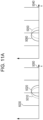
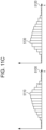
- the search area size is obtained on the basis of a characteristic related to the amount of a shift of discretization position at the time of image acquisition between the first image and the second image. Specifically, the characteristic that the position of a voxel at which an original image pickup signal of a subject is most reflected shifts between the first image and the second image by the sum of halves of voxel sizes of the respective images at most is used. This characteristic will be described later with reference to Fig. 11 .
- a shift is generated between the positions of voxels where the signal is most reflected. Due to a shift of discretization position of a signal, the voxel where the signal is most reflected is assumed to shift by half a voxel at most from the position of the original signal.
- interpolation processing is successively performed on the second image in a range of the search area ⁇ _pos2 and the interpolation results and I1(pos1) are compared with each other.
- a truly successive interpolation processing requires an infinite number of times of interpolation processing and comparison processing.
- the search area ⁇ _pos2 is sampled with an appropriate step size, and a finite number of times of processing is performed at the sampling positions to obtain an approximate solution.
- This embodiment will describe, instead of the above method for obtaining an approximate solution, a method of a finite number of times of calculation processing to obtain a solution that is theoretically obtained by successive interpolation processing.
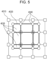
- FIG. 5 a diagram of a two-dimensional case is illustrated as an example in this description for the convenience of description on paper.
- reference numeral 4010 denotes the voxels constituting the second image
- reference numeral 4020 denotes the search area ⁇ _pos2 that is set through the processing in step S2050.
- Reference numeral 4030 denotes the rectangular parallelepiped areas obtained by dividing the search area 4020. In this processing step, processing for dividing the search area 4020 into the rectangular parallelepiped areas 4030 by a method described below is performed.
- intersection points between the outline of the search area 4020 and lines connecting adjacent voxels among the voxels 4010 are set as division vertices 4040.
- the vertex positions of the search area 4020 are similarly set as the division vertices 4040.
- positions of voxels included in the search area 4020 are also set as the division vertices 4040.
- the search area 4020 is divided into rectangular parallelepiped areas having the division vertices 4040 that are set through the above processing to obtain the rectangular parallelepiped areas 4030.
- N_sr rectangular parallelepiped areas 4030 will be described as an example.
- Positions of the vertices 4040 of the divided rectangular parallelepiped areas 4030 are denoted by V_ij in this embodiment.
- a subscript i represents an index of the N_sr rectangular parallelepipeds.
- j represents an index of each of the eight vertices of a rectangular parallelepiped. That is, 1 ⁇ i ⁇ N_sr and 1 ⁇ j ⁇ 8 are satisfied.
- step S20606 the difference obtaining unit 1070 performs processing for obtaining a maximum I2_max and a minimum I2_min of the intensity I2_s_ij (1 ⁇ i ⁇ N_sr, 1 ⁇ j ⁇ 8) at all the vertex positions obtained in step S20604.
- I 2 _ max max 1 ⁇ i ⁇ N _ sr , 1 ⁇ j ⁇ 8 I 2 _ s _ ij
- I 2 _ min min 1 ⁇ i ⁇ N _ sr , 1 ⁇ j ⁇ 8 I 2 _ s _ ij
- the difference obtaining unit 1070 is an example of second obtaining means that obtains a maximum or a minimum of a voxel value or an interpolated value within a search area on the basis of at least one of a voxel value included in a partial area included in the search area and an interpolated value obtained by interpolation of a voxel of the second image, which is the target image.
- a vertex position V_ij of a rectangular parallelepiped area 4030 may be identical with a voxel of the second image.
- the intensity I2_s_ij is the voxel value of the voxel.
- the intensity I2_s_ij is at least one of a voxel value and an interpolated value within the search area.
- the difference obtaining unit 1070 performs processing for obtaining the difference value I_diff on the basis of the intensity I1(pos1) at the position of interest posi in the first image obtained in step S2040 and the maximum I2_max and minimum I2_min obtained in S20606.
- the difference value I_diff is obtained by calculation illustrated in Math 2.
- I _ diff ⁇ 0 : where I 2 _ min ⁇ I 1 pos 1 ⁇ I 2 _ max I 1 pos 1 ⁇ I 2 _ min : where I 1 ⁇ I 2 _ min I 1 pos 1 ⁇ I 2 _ max : I 1 > I 2 _ max
- the difference value I_diff a value having the smallest absolute value is set among possible values as difference values between I1(pos1) and I2 at various positions within the search area.
- step S2060 in this embodiment is performed.
- the above processing corresponds to processing for obtaining a maximum and a minimum of the intensity in a case where linear interpolation processing is performed on the second image within the search area 4020 and for obtaining a difference value by comparing the maximum and minimum with an intensity at a position of interest in the first image.
- This can be confirmed as follows. That is, (1) an intensity in an interpolated image obtained by linear interpolation of image with a predetermined rectangular parallelepiped area does not exceed the range between the maximum and the minimum of the intensity at the vertex positions of the rectangular parallelepiped.
- any intensity between the maximum and the minimum of the interpolated value exists within the area.
- the maximum and the minimum of the intensity in a case where linear interpolation is performed in the rectangular parallelepiped area correspond with the maximum and the minimum of the intensity at the vertex positions of the rectangular parallelepiped.
- the maximum and the minimum of the intensity in a case where linear interpolation is performed in a given area constituted by combining a plurality of rectangular parallelepipeds correspond with the maximum and the minimum of the intensity at the vertex positions of each of the rectangular parallelepipeds constituting the area.
- any interpolation processing may be performed as long as the range between the maximum and the minimum of the intensity at the vertex positions are not exceeded by the interpolation processing.
- interpolation processing by which the range between the maximum and the minimum of the intensity at the vertex positions may be exceeded, use of the maximum and the minimum of the intensity at the vertex positions as approximates of the maximum and the minimum of the intensity in an interpolated area is also an embodiment of the present invention.
- the difference value between the intensity within the range of the search area 4020 and the intensity at the position of interest in the first image can be efficiently obtained.
- step S2070 the position obtaining unit 1050 determines whether the difference value has been obtained at all positions in the first image. If the difference value at all positions has been obtained, the processing proceeds to step S2080. On the other hand, if the difference value at all positions has not been obtained, the processing returns to step S2040. Then, a position (voxel) at which the difference value is yet to be obtained in the first image is set as a new position of interest (voxel of interest), and the processing in and after step S2040 is performed again.
- the difference value may be obtained not at all positions (all voxels) in the first image, but at some positions in the first image that are extracted in advance by a known image processing technique, for example, only voxels representing an area of an organ of interest.
- positions of interest may be voxels that are thinned out at a predetermined interval. This can reduce a processing time required for reducing noise.
- a tomography image or a projection image of each image may be displayed.
- a screen may be longitudinally or laterally divided to arrange the first image, the second image, and the subtraction image for display.
- a subtraction image drawn in different color from the first image or the second image may be superposed for display, or only one of the first image, the second image, and the subtraction image may be selected (may be freely switched at the same position) for display.
- other images may be enlarged or reduced for display, or the respective images may be arranged for display such that the corresponding position in the second image corresponding to the single position of interest in the first image matches the position of interest in the subtraction image.
- the difference value obtained by searching an area of an appropriate size considering a shift of discretization position can be obtained with a high calculation efficiency. This makes it possible to provide a user with a subtraction image in which necessary signals in the subtraction image remain and noise generated from a difference in intensity due to a shift of discretization position between images is reduced.
- the first embodiment of the present invention has described as an example a case where the shape of the search area that is set in step S2050 is a rectangular parallelepiped.
- the implementation of the present invention is not limited to this, and a given shape may be employed.
- the search area may be an ellipsoid area having a size determined on the basis of the search area size obtained in step S2030. This case will be described with reference to Fig. 6 .
- reference numeral 4010 denotes the voxels constituting the second image.
- Reference numeral 4021 denotes an ellipsoid search area that is set in step S2050 on the basis of the search area size obtained in step S2030.
- diameters of the ellipsoid in the axis directions can be set on the basis of the size Sx, Sy, Sz in the axis directions obtained in step S2030.
- constant multiples of Sx, Sy, Sz are set as the diameters of the ellipsoid in the axis directions.
- step S20604 is performed on the rectangular parallelepiped set 4033.
- the number of parts obtained by the dividing may be other numbers (for example, three parts may be generated by the dividing, or the dividing may not be performed).
- an appropriate search area in accordance with imaging characteristics (e.g., discretization characteristics) of a modality that picks up the first image and the second image can be set. This produces an effect of obtaining a subtraction image with a higher quality.
- Fig. 1 is used as a diagram for describing the functional configuration of the image processing apparatus according to this embodiment. A detailed description is omitted herein.
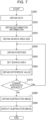
- Fig. 7 illustrates an entire processing flow executed by the image processing apparatus according to the second embodiment.
- the processing from step S3000 to step S3050 in the second embodiment is substantially the same as the processing from step S2000 to step S2050 in the first embodiment, and thus, description is omitted herein.
- the processing from step S3070 to step S3090 is substantially the same as the processing from step S2070 to step S2090 in the first embodiment, and thus, description is omitted herein.
- step S3060 of which the processing content is different from that in the first embodiment will be described.
- step S3060 on the basis of the intensity at the position of interest pos1 in the first image and the intensity in the second image in the search area ⁇ _pos2 that is set in step S3030, the difference obtaining unit 1070 obtains the difference value to be given to the subtraction image. Then, the difference obtaining unit 1070 outputs the obtained difference value to the subtraction image obtaining unit 1080.
- Fig. 8 is a flowchart for specifically describing the processing in step S3060 performed by the image processing apparatus in the second embodiment. The following description is given in accordance with the flowchart.
- step S30601 the difference obtaining unit 1070 performs processing for obtaining an intensity I1_s at the position of interest in the first image.
- step S30602 the difference obtaining unit 1070 performs processing for dividing the search area that is set in step S3050 into a plurality of rectangular parallelepipeds. This processing is substantially the same as the processing in step S20602 in the first embodiment, and thus, a detailed description is omitted.
- step S30603 the difference obtaining unit 1070 initializes scalar variables I_max and I_min to the value 0, which are to be reset through repetitive processing from step S30604 to step S30608, which will be described later.
- step S30604 the processing from step S30604 to step S30608 is repetitively performed.
- the variables I_max and I_min are reset as appropriate.
- step S30604 from among the plurality of vertex positions V_ij as processing targets, the difference obtaining unit 1070 selects a vertex for which the processing in and after step S30605, which will be described later, is yet to be performed, and the processing proceeds to the following step.
- step S30604 to step S30608 is repetitively performed in a double loop while changing each of i and j, which are subscripts of V_ij, in ascending order. Then, a case will be described where it is determined in step S30608 whether the processing at all the vertices has ended.
- the vertex position selected in step S30604 is V_sel.
- This processing is performed as substantially the same processing as that in step S20604 in the first embodiment, and thus, a detailed description is omitted herein.
- step S30606 the difference obtaining unit 1070 performs processing for resetting the variables I_max and I_min on the basis of the intensity I2_sel obtained in step S30604. Specifically, if the variable I_max before execution of this processing step is less than I2_sel, the difference obtaining unit 1070 resets I_max to I2_sel. In addition, if the variable I_min is greater than I2_sel, the difference obtaining unit 1070 resets I_min to I2_sel. Note that if this processing step is initially performed, regardless of the values of the variables I_max and I_min before execution of this processing step, the respective variables are reset to I2_sel.
- step S30607 the difference obtaining unit 1070 determines whether the intensity I1_s at the position of interest in the first image obtained in step S30601 and the values of the variables I max and I_min reset in step S30606 satisfy a predetermined condition.
- the predetermined condition is, for example, a magnitude relationship among the intensity I1_s, the maximum I_max, and the minimum I_min. Specifically, if I_min ⁇ I1_s ⁇ I_max is satisfied, the reset processing of the maximum and the minimum is stopped, and the processing proceeds to step S30609. On the other hand, if not, the processing proceeds to step S30608.
- step S30608 the difference obtaining unit 1070 determines whether processing has been performed for all the vertex positions V_ij of the divided rectangular parallelepipeds obtained in step S30602. If processing has been performed for all the vertex positions V_ij, the processing proceeds to step S30609. If not, the processing proceeds to step S30604 to continue the processing related to the vertex positions for which processing is yet to be performed.
- step S30609 the difference obtaining unit 1070 obtains the difference value I_diff on the basis of I1_s obtained in step S30601 and I_max and I_min reset through the repetitive processing from step S30604 to step S30608.
- I_diff is obtained by calculation processing illustrated in Math 3.
- I _ diff ⁇ 0 : where I _ min ⁇ I 1 _ s ⁇ I _ max I 1 _ s ⁇ I _ min : where I 1 ⁇ I _ min I 1 _ s ⁇ I _ max : I 1 _ s > I _ max
- step S3060 in this embodiment is performed.
- the processing of the image processing apparatus according to the second embodiment is performed. Since the second embodiment has an effect of reducing the number of times of image interpolation processing at vertex positions compared with the first embodiment, an effect of performing processing with a higher calculation efficiency is produced.
- step S3060 a case where processing is sequentially performed while changing each of i and j, which are subscripts of the vertex positions V_ij of the rectangular parallelepipeds obtained by the dividing in step S30602, in ascending order has been described as an example.
- the implementation of the present invention is not limited to this.
- the difference obtaining unit 1070 defines the order of processing on the basis of a level of calculation cost for obtaining the voxel value or interpolated value at a vertex position.
- step S30604 the difference obtaining unit 1070 may preferentially select from V_ij a vertex at the position identical with the position of a voxel of the second image (vertex position at which the voxel value is directly available as the intensity without interpolation).
- V_ij a vertex at the position identical with the position of a voxel of the second image (vertex position at which the voxel value is directly available as the intensity without interpolation).
- the repetitive processing from step S30604 to step S30608 may be stopped without performing operation for all the vertices. Accordingly, by changing the processing order by the above method, further increase in calculation efficiency is expected compared to the second embodiment.
- step S3060 in the above second embodiment a case where the processing from step S30604 to step S30606 is repetitively performed so as to obtain the maximum and the minimum of the intensity in the second image within the search area has been described as an example.
- the implementation of the present invention is not limited to this.
- the repetitive processing from step S30604 to step S30606 is initially performed, it is determined whether the intensity at the vertex position as a processing target obtained in step S30605 is greater than or less than the intensity at the position of interest in the first image.
- step S3060 a case where the vertex positions V_ij for which processing is yet to be performed are sequentially selected without conditions as the vertex position as a processing target in step S30604 to perform the processing from step S30605 to S30607 has been described as an example.
- the implementation of the present invention is not limited to this.
- the following condition determination may be made in step S30604, and depending on the result, it may be selected whether to perform the processing from step S30605 to step S30607.
- a processing method in this case will be described with reference to Fig. 9 .
- reference numerals 40101 to 40104 denote voxels of the second image.
- reference numerals 40401 to 40404 denote vertex positions of a rectangular parallelepiped obtained by the dividing in step S30602.
- the intensity at this position in the second image is obtained by interpolation of a voxel value from the voxels 40101 to 40104.
- I_min and I_max are reset.
- step S30605 to step S30607 for this vertex may be skipped. That is, by assuming that processing for this vertex position has already been performed, the processing may proceed to step S30608 without performing the processing from step S30605 to S30607. Even if the processing is performed in this manner, the difference value obtained in step S3060 is equal to the difference value obtained if the processing is performed as in the second embodiment.
- the number of times of interpolation processing of the intensity in the second image can be reduced without changing the calculation results. Accordingly, further increase in calculation efficiency is expected compared to the second embodiment.
- the data obtaining unit 1010 obtains the first image and the second image from the data server 110 as an example.
- the implementation of the present invention is not limited to this.
- the data obtaining unit 1010 may obtain at least one of the first image and the second image from a modality (not illustrated).
- the present invention can be implemented by a process in which a program for implementing one or more functions in the above embodiments is supplied to a system or an apparatus via a network or a storage medium and one or more processors in a computer of the system or apparatus reads and executes the program.
- the present invention can also be implemented by a circuit (e.g., ASIC) for implementing one or more functions.
- the image processing apparatus in each of the above embodiments may be realized as a standalone apparatus, or the above-described processing may be performed by combining a plurality of apparatuses so that mutual communication is possible. Either form is included in the embodiments of the present invention.
- the above-described processing may also be performed by a shared server apparatus or server group.
- the image processing apparatus and a plurality of apparatuses that constitute an image processing system are at least capable of performing communication at a predetermined communication rate and are not necessarily present in the same facility or the same country.
- the embodiments of the present invention include a form in which a software program for implementing the functions in the above embodiments is supplied to a system or an apparatus and a computer of the system or apparatus reads and executes the code of the supplied program.
- the program code itself to be installed in the computer in order to perform the processing according to the embodiments with the computer is another embodiment of the present invention.
- an OS or the like running on the computer may perform part or all of the actual processing, and the processing may implement the functions in the above embodiments.
Landscapes
- Engineering & Computer Science (AREA)
- Physics & Mathematics (AREA)
- General Physics & Mathematics (AREA)
- Theoretical Computer Science (AREA)
- Health & Medical Sciences (AREA)
- Medical Informatics (AREA)
- Life Sciences & Earth Sciences (AREA)
- General Health & Medical Sciences (AREA)
- Nuclear Medicine, Radiotherapy & Molecular Imaging (AREA)
- Radiology & Medical Imaging (AREA)
- Quality & Reliability (AREA)
- Computer Vision & Pattern Recognition (AREA)
- Biophysics (AREA)
- High Energy & Nuclear Physics (AREA)
- Optics & Photonics (AREA)
- Pathology (AREA)
- Biomedical Technology (AREA)
- Heart & Thoracic Surgery (AREA)
- Molecular Biology (AREA)
- Surgery (AREA)
- Animal Behavior & Ethology (AREA)
- Public Health (AREA)
- Veterinary Medicine (AREA)
- Apparatus For Radiation Diagnosis (AREA)
- Image Processing (AREA)
- Magnetic Resonance Imaging Apparatus (AREA)
- Image Analysis (AREA)
Claims (12)
- Bildverarbeitungsvorrichtung (100) miteiner ersten Erhalteeinrichtung (1010) zum Erhalten eines Zielbildes und eines Referenzbildes, wobei das Zielbild und das Referenzbild durch einen Satz von Volumenelementen gebildet werden, die auf diskretisierte Weise angeordnet sind,einer Einstelleinrichtung (1060) zum Einstellen eines Suchbereichs (4020) in dem Zielbild auf der Grundlage einer entsprechenden Position (4015), die eine Position in dem Zielbild ist, die einer interessierenden Position im Referenzbild entspricht, wobei der Suchbereich (4020) ein Bereich ist, in dem die entsprechende Position (4015) enthalten ist, und ein Teil des Zielbildes ist,einer Teilungseinrichtung (1070) zum Unterteilen des Suchbereichs (4020) in eine Vielzahl von Teilbereichen (4030) auf der Grundlage von Positionen der Volumenelemente des Zielbildes und von Schnittpunkten zwischen einem Umriss des Suchbereichs (4020) und von Linien, die angrenzende Volumenelemente unter den Volumenelementen verbinden,einer zweiten Erhalteeinrichtung (1070) zum Erhalten eines Maximums und/oder eines Minimums eines Volumenelementwerts und eines interpolierten Werts in dem Suchbereich (4020) auf der Grundlage eines in dem Teilbereich (4030) enthaltenen Volumenwerts und/oder eines interpolierten Werts, der durch Interpolieren eines Volumenelements des Zielbildes an einer Scheitelpunktposition (4040) des Teilbereichs (4030) erhalten wird, undeiner dritten Erhalteeinrichtung zum Erhalten eines Vergleichswerts über eine Vergleichsoperation zwischen dem Maximum und/oder dem Minimum, das durch die zweite Erhalteeinrichtung erhalten wird, und eines Volumenelementwerts an der interessierenden Position in dem Referenzbild.
- Bildverarbeitungsvorrichtung nach Anspruch 1, wobei bei der Vergleichsoperation zwischen dem Maximum und/oder dem Minimum und dem Volumenelementwert an der interessierenden Position die dritte Erhalteeinrichtung als den Vergleichswert einen Wert mit einem kleinsten Absolutwert unter möglichen Werten als Differenzwerte zwischen dem Volumenelementwert und dem Volumenelementwert und dem interpolierten Wert in dem Suchbereich erhält.
- Bildverarbeitungsvorrichtung nach Anspruch 1 oder 2, wobei die dritte Erhalteeinrichtung (1) den Vergleichswert auf 0 setzt, wenn der Volumenelementwert an der interessierenden Position kleiner als das oder gleich dem Maximum und größer als das oder gleich dem Minimum ist, (2) den Vergleichswert auf einen Differenzwert zwischen dem Volumenelementwert und dem Maximum setzt, wenn der Volumenelementwert an der interessierenden Position größer als das Maximum ist, und (3) den Vergleichswert auf einen Differenzwert zwischen dem Volumenelementwert und dem Minimum setzt, wenn der Volumenelementwert an der interessierenden Position kleiner als das Minimum ist.
- Bildverarbeitungsvorrichtung nach einem der Ansprüche 1 bis 3, wobei die dritte Erhalteeinrichtung eine wiederholte Verarbeitung zum Erhalten des Maximums und des Minimums durchführt, während sie einen Scheitelpunkt als Verarbeitungsziel unter Scheitelpunkten jedes Teilbereichs, der in dem Suchbereich enthalten ist, sequentiell umschaltet, und, wenn eine Größenbeziehung zwischen dem Volumenelementwert an der interessierenden Position in dem Referenzbild, dem Maximum und dem Minimum eine vorbestimmte Bedingung erfüllt, die wiederholte Verarbeitung beendet.
- Bildverarbeitungsvorrichtung nach Anspruch 4, wobei die vorbestimmte Bedingung darin besteht, dass der Volumenelementwert an der interessierenden Position kleiner als das oder gleich dem Maximum und größer als das oder gleich dem Minimum ist.
- Bildverarbeitungsvorrichtung nach Anspruch 4 oder 5, wobei die dritte Erhalteeinrichtung bei der wiederholten Verarbeitung eine Verarbeitungsreihenfolge auf der Grundlage einer Stufe von Berechnungskosten zum Erhalten des Volumenelementwerts und interpolierten Werts des Zielbildes an der Scheitelpunktposition definiert.
- Bildverarbeitungsvorrichtung nach einem der Ansprüche 1 bis 6, wobei die dritte Erhalteeinrichtung Informationen hinsichtlich der entsprechenden Position auf der Grundlage der interessierenden Position im Referenzbild und von Informationen hinsichtlich einer Deformation zum Registrieren zwischen dem Zielbild und dem Referenzbild erhält.
- Bildverarbeitungsvorrichtung nach einem der Ansprüche 1 bis 7, ferner mit einer vierten Erhalteeinrichtung zum Erhalten eines Subtraktionsbildes auf der Grundlage des durch die dritte Erhalteeinrichtung erhaltenen Vergleichswerts.
- Bildverarbeitungsvorrichtung nach einem der Ansprüche 1 bis 8, ferner mit einer Anzeigesteuereinrichtung zum Veranlassen einer Anzeigeeinheit zum Anzeigen eines Subtraktionsbildes, das auf der Grundlage des durch die dritte Erhalteeinrichtung erhaltenen Vergleichswerts erhalten wird.
- Bildverarbeitungsvorrichtung nach einem der Ansprüche 1 bis 9, wobei der Suchbereich ein rechtwinkliger Parallelepipedbereich parallel zu Bildkoordinatenachsen des Zielbildes ist.
- Bildverarbeitungsverfahren mit:einem Schritt zum Erhalten eines Zielbildes und eines Referenzbildes, wobei das Zielbild und das Referenzbild durch einen Satz von Volumenelementen gebildet sind, die auf diskretisierte Weise angeordnet sind,einem Schritt zum Einstellen eines Suchbereichs (4020) in dem Zielbild auf der Grundlage einer entsprechenden Position (4015), die eine Position in dem Zielbild ist, die einer interessierenden Position in dem Referenzbild entspricht, wobei der Suchbereich (4020) ein Bereich ist, in dem die entsprechende Position (4015) enthalten ist, und ein Teil des Zielbildes ist, undeinem Schritt zum Unterteilen des Suchbereichs (4020) in eine Vielzahl von Teilbereichen (4030) auf der Grundlage von Positionen der Volumenelemente des Zielbildes und von Schnittpunkten zwischen einem Umriss des Suchbereichs (4020) und Linien, die angrenzende Volumenelemente unter den Volumenelementen verbinden,einem Schritt zum Erhalten eines Maximums und/oder eines Minimums eines Volumenelementwerts und eines interpolierten Werts in dem Suchbereich (4020) auf der Grundlage eines in dem Teilbereich (4030) enthaltenen Volumenelementwerts und/oder eines interpolierten Werts, der durch Interpolation eines Volumenelements des Zielbildes an einer Scheitelpunktposition (4040) des Teilbereichs (4030) erhalten wird, undeinem Schritt zum Erhalten eines Vergleichswerts über eine Vergleichsoperation zwischen dem Maximum und/oder dem Minimum und einem Volumenelementwert an der interessierenden Position im Referenzbild.
- Programm, das einen Computer zur Durchführung des Bildverarbeitungsverfahrens nach Anspruch 11 veranlasst.
Applications Claiming Priority (2)
| Application Number | Priority Date | Filing Date | Title |
|---|---|---|---|
| JP2017150877A JP7140475B2 (ja) | 2017-08-03 | 2017-08-03 | 画像処理装置、画像処理方法、画像処理システム及びプログラム |
| PCT/JP2018/027609 WO2019026680A1 (ja) | 2017-08-03 | 2018-07-24 | 画像処理装置、画像処理方法、画像処理システム及びプログラム |
Publications (3)
| Publication Number | Publication Date |
|---|---|
| EP3662835A1 EP3662835A1 (de) | 2020-06-10 |
| EP3662835A4 EP3662835A4 (de) | 2021-04-28 |
| EP3662835B1 true EP3662835B1 (de) | 2024-12-04 |
Family
ID=65232548
Family Applications (1)
| Application Number | Title | Priority Date | Filing Date |
|---|---|---|---|
| EP18840604.5A Active EP3662835B1 (de) | 2017-08-03 | 2018-07-24 | Bildverarbeitungsvorrichtung, bildverarbeitungsverfahren, bildverarbeitungssystem und programm |
Country Status (4)
| Country | Link |
|---|---|
| US (1) | US11302007B2 (de) |
| EP (1) | EP3662835B1 (de) |
| JP (1) | JP7140475B2 (de) |
| WO (1) | WO2019026680A1 (de) |
Families Citing this family (3)
| Publication number | Priority date | Publication date | Assignee | Title |
|---|---|---|---|---|
| BR112022002552A2 (pt) * | 2019-08-15 | 2022-05-03 | Ericsson Telefon Ab L M | Nó de rede configurado para se comunicar com um dispositivo sem fio, método em um nó de rede configurado para se comunicar com um dispositivo sem fio, dispositivo sem fio e método em um dispositivo sem fio |
| WO2021034056A1 (ko) * | 2019-08-16 | 2021-02-25 | 엘지전자 주식회사 | 사물 인터넷을 지원하는 무선 통신 시스템에서 하향링크 정보를 송수신하는 방법 및 이를 위한 장치 |
| WO2023119420A1 (ja) * | 2021-12-21 | 2023-06-29 | 株式会社ソシオネクスト | 画像処理装置、画像処理方法および画像処理プログラム |
Citations (1)
| Publication number | Priority date | Publication date | Assignee | Title |
|---|---|---|---|---|
| EP2312531B1 (de) * | 2009-09-30 | 2013-01-02 | FUJIFILM Corporation | Computergestützte Diagnose von zeitlichen Veränderungen |
Family Cites Families (8)
| Publication number | Priority date | Publication date | Assignee | Title |
|---|---|---|---|---|
| US7310437B2 (en) * | 2000-03-08 | 2007-12-18 | Fujifilm Corporation | Image processing method and system, and storage medium |
| WO2005009242A1 (ja) * | 2003-07-28 | 2005-02-03 | Hitachi Medical Corporation | 医用画像処理装置及び方法 |
| JP4626984B2 (ja) * | 2005-02-21 | 2011-02-09 | 株式会社日立メディコ | 差分画像生成装置及び方法 |
| DE602007002693D1 (de) * | 2007-02-09 | 2009-11-19 | Agfa Gevaert | Visuelle Hervorhebung von Intervalländerungen mittels einer Zeitsubtraktionstechnik |
| US20090074276A1 (en) * | 2007-09-19 | 2009-03-19 | The University Of Chicago | Voxel Matching Technique for Removal of Artifacts in Medical Subtraction Images |
| JP5921119B2 (ja) | 2011-09-02 | 2016-05-24 | 株式会社東芝 | X線診断装置 |
| US9760983B2 (en) * | 2015-10-19 | 2017-09-12 | Shanghai United Imaging Healthcare Co., Ltd. | System and method for image registration in medical imaging system |
| JP6432543B2 (ja) | 2016-02-23 | 2018-12-05 | 株式会社デンソー | 経路計算システム及びコンピュータプログラム |
-
2017
- 2017-08-03 JP JP2017150877A patent/JP7140475B2/ja active Active
-
2018
- 2018-07-24 WO PCT/JP2018/027609 patent/WO2019026680A1/ja not_active Ceased
- 2018-07-24 EP EP18840604.5A patent/EP3662835B1/de active Active
-
2020
- 2020-01-22 US US16/749,894 patent/US11302007B2/en active Active
Patent Citations (1)
| Publication number | Priority date | Publication date | Assignee | Title |
|---|---|---|---|---|
| EP2312531B1 (de) * | 2009-09-30 | 2013-01-02 | FUJIFILM Corporation | Computergestützte Diagnose von zeitlichen Veränderungen |
Also Published As
| Publication number | Publication date |
|---|---|
| JP7140475B2 (ja) | 2022-09-21 |
| EP3662835A1 (de) | 2020-06-10 |
| EP3662835A4 (de) | 2021-04-28 |
| US11302007B2 (en) | 2022-04-12 |
| JP2019025240A (ja) | 2019-02-21 |
| WO2019026680A1 (ja) | 2019-02-07 |
| US20200160526A1 (en) | 2020-05-21 |
Similar Documents
| Publication | Publication Date | Title |
|---|---|---|
| US8907952B2 (en) | Reparametrized bull's eye plots | |
| US10803354B2 (en) | Cross-modality image synthesis | |
| EP3508127B1 (de) | Bildverarbeitungsvorrichtung, bildverarbeitungsverfahren und programm | |
| US8165361B2 (en) | System and method for image based multiple-modality cardiac image alignment | |
| US20110262015A1 (en) | Image processing apparatus, image processing method, and storage medium | |
| WO2021144230A1 (en) | Method and system for automatically detecting anatomical structures in a medical image | |
| JP6316671B2 (ja) | 医療画像処理装置および医用画像処理プログラム | |
| US20150043799A1 (en) | Localization of Anatomical Structures Using Learning-Based Regression and Efficient Searching or Deformation Strategy | |
| US11229377B2 (en) | System and method for next-generation MRI spine evaluation | |
| US11302007B2 (en) | Image processing apparatus, image processing method, image processing system, and storage medium | |
| US11657909B2 (en) | Medical image processing apparatus and medical image processing method | |
| JP6772123B2 (ja) | 画像処理装置、画像処理方法、画像処理システムおよびプログラム | |
| JP2019146926A (ja) | 画像処理装置、画像処理方法およびプログラム | |
| KR20130016942A (ko) | 3차원 볼륨 파노라마 영상 생성 방법 및 장치 | |
| US20100092059A1 (en) | Creation Of Motion Compensated MRI M-Mode Images Of The Myocardial Wall | |
| US8957891B2 (en) | Anatomy-defined automated image generation | |
| CN118985004A (zh) | 根据展开扫描图像的自动肋骨骨折检测 | |
| US12089976B2 (en) | Region correction apparatus, region correction method, and region correction program | |
| JPWO2019058657A1 (ja) | 流体解析装置および流体解析装置の作動方法並びに流体解析プログラム | |
| JP2018106560A (ja) | 画像処理装置、画像処理方法、画像処理システム及びプログラム | |
| US12374002B2 (en) | Image processing apparatus, method and program, learning apparatus, method and program, and derivation model | |
| JP7846422B2 (ja) | スキャンの高速評価のための結合された肋骨及び脊椎の画像処理 |
Legal Events
| Date | Code | Title | Description |
|---|---|---|---|
| STAA | Information on the status of an ep patent application or granted ep patent |
Free format text: STATUS: THE INTERNATIONAL PUBLICATION HAS BEEN MADE |
|
| PUAI | Public reference made under article 153(3) epc to a published international application that has entered the european phase |
Free format text: ORIGINAL CODE: 0009012 |
|
| STAA | Information on the status of an ep patent application or granted ep patent |
Free format text: STATUS: REQUEST FOR EXAMINATION WAS MADE |
|
| 17P | Request for examination filed |
Effective date: 20200303 |
|
| AK | Designated contracting states |
Kind code of ref document: A1 Designated state(s): AL AT BE BG CH CY CZ DE DK EE ES FI FR GB GR HR HU IE IS IT LI LT LU LV MC MK MT NL NO PL PT RO RS SE SI SK SM TR |
|
| AX | Request for extension of the european patent |
Extension state: BA ME |
|
| DAV | Request for validation of the european patent (deleted) | ||
| DAX | Request for extension of the european patent (deleted) | ||
| A4 | Supplementary search report drawn up and despatched |
Effective date: 20210325 |
|
| RIC1 | Information provided on ipc code assigned before grant |
Ipc: A61B 6/00 20060101AFI20210319BHEP Ipc: G06T 1/00 20060101ALI20210319BHEP Ipc: G06T 5/00 20060101ALI20210319BHEP |
|
| STAA | Information on the status of an ep patent application or granted ep patent |
Free format text: STATUS: EXAMINATION IS IN PROGRESS |
|
| 17Q | First examination report despatched |
Effective date: 20230316 |
|
| GRAP | Despatch of communication of intention to grant a patent |
Free format text: ORIGINAL CODE: EPIDOSNIGR1 |
|
| STAA | Information on the status of an ep patent application or granted ep patent |
Free format text: STATUS: GRANT OF PATENT IS INTENDED |
|
| INTG | Intention to grant announced |
Effective date: 20240627 |
|
| GRAS | Grant fee paid |
Free format text: ORIGINAL CODE: EPIDOSNIGR3 |
|
| GRAA | (expected) grant |
Free format text: ORIGINAL CODE: 0009210 |
|
| STAA | Information on the status of an ep patent application or granted ep patent |
Free format text: STATUS: THE PATENT HAS BEEN GRANTED |
|
| AK | Designated contracting states |
Kind code of ref document: B1 Designated state(s): AL AT BE BG CH CY CZ DE DK EE ES FI FR GB GR HR HU IE IS IT LI LT LU LV MC MK MT NL NO PL PT RO RS SE SI SK SM TR |
|
| REG | Reference to a national code |
Ref country code: GB Ref legal event code: FG4D |
|
| REG | Reference to a national code |
Ref country code: CH Ref legal event code: EP |
|
| REG | Reference to a national code |
Ref country code: DE Ref legal event code: R096 Ref document number: 602018077328 Country of ref document: DE |
|
| REG | Reference to a national code |
Ref country code: IE Ref legal event code: FG4D |
|
| REG | Reference to a national code |
Ref country code: LT Ref legal event code: MG9D |
|
| REG | Reference to a national code |
Ref country code: NL Ref legal event code: MP Effective date: 20241204 |
|
| PG25 | Lapsed in a contracting state [announced via postgrant information from national office to epo] |
Ref country code: HR Free format text: LAPSE BECAUSE OF FAILURE TO SUBMIT A TRANSLATION OF THE DESCRIPTION OR TO PAY THE FEE WITHIN THE PRESCRIBED TIME-LIMIT Effective date: 20241204 |
|
| PG25 | Lapsed in a contracting state [announced via postgrant information from national office to epo] |
Ref country code: FI Free format text: LAPSE BECAUSE OF FAILURE TO SUBMIT A TRANSLATION OF THE DESCRIPTION OR TO PAY THE FEE WITHIN THE PRESCRIBED TIME-LIMIT Effective date: 20241204 |
|
| PG25 | Lapsed in a contracting state [announced via postgrant information from national office to epo] |
Ref country code: BG Free format text: LAPSE BECAUSE OF FAILURE TO SUBMIT A TRANSLATION OF THE DESCRIPTION OR TO PAY THE FEE WITHIN THE PRESCRIBED TIME-LIMIT Effective date: 20241204 |
|
| PG25 | Lapsed in a contracting state [announced via postgrant information from national office to epo] |
Ref country code: ES Free format text: LAPSE BECAUSE OF FAILURE TO SUBMIT A TRANSLATION OF THE DESCRIPTION OR TO PAY THE FEE WITHIN THE PRESCRIBED TIME-LIMIT Effective date: 20241204 |
|
| PG25 | Lapsed in a contracting state [announced via postgrant information from national office to epo] |
Ref country code: NO Free format text: LAPSE BECAUSE OF FAILURE TO SUBMIT A TRANSLATION OF THE DESCRIPTION OR TO PAY THE FEE WITHIN THE PRESCRIBED TIME-LIMIT Effective date: 20250304 |
|
| PG25 | Lapsed in a contracting state [announced via postgrant information from national office to epo] |
Ref country code: LV Free format text: LAPSE BECAUSE OF FAILURE TO SUBMIT A TRANSLATION OF THE DESCRIPTION OR TO PAY THE FEE WITHIN THE PRESCRIBED TIME-LIMIT Effective date: 20241204 Ref country code: GR Free format text: LAPSE BECAUSE OF FAILURE TO SUBMIT A TRANSLATION OF THE DESCRIPTION OR TO PAY THE FEE WITHIN THE PRESCRIBED TIME-LIMIT Effective date: 20250305 |
|
| PG25 | Lapsed in a contracting state [announced via postgrant information from national office to epo] |
Ref country code: RS Free format text: LAPSE BECAUSE OF FAILURE TO SUBMIT A TRANSLATION OF THE DESCRIPTION OR TO PAY THE FEE WITHIN THE PRESCRIBED TIME-LIMIT Effective date: 20250304 |
|
| PG25 | Lapsed in a contracting state [announced via postgrant information from national office to epo] |
Ref country code: NL Free format text: LAPSE BECAUSE OF FAILURE TO SUBMIT A TRANSLATION OF THE DESCRIPTION OR TO PAY THE FEE WITHIN THE PRESCRIBED TIME-LIMIT Effective date: 20241204 |
|
| REG | Reference to a national code |
Ref country code: AT Ref legal event code: MK05 Ref document number: 1747251 Country of ref document: AT Kind code of ref document: T Effective date: 20241204 |
|
| PG25 | Lapsed in a contracting state [announced via postgrant information from national office to epo] |
Ref country code: SM Free format text: LAPSE BECAUSE OF FAILURE TO SUBMIT A TRANSLATION OF THE DESCRIPTION OR TO PAY THE FEE WITHIN THE PRESCRIBED TIME-LIMIT Effective date: 20241204 |
|
| PG25 | Lapsed in a contracting state [announced via postgrant information from national office to epo] |
Ref country code: PL Free format text: LAPSE BECAUSE OF FAILURE TO SUBMIT A TRANSLATION OF THE DESCRIPTION OR TO PAY THE FEE WITHIN THE PRESCRIBED TIME-LIMIT Effective date: 20241204 |
|
| PG25 | Lapsed in a contracting state [announced via postgrant information from national office to epo] |
Ref country code: IS Free format text: LAPSE BECAUSE OF FAILURE TO SUBMIT A TRANSLATION OF THE DESCRIPTION OR TO PAY THE FEE WITHIN THE PRESCRIBED TIME-LIMIT Effective date: 20250404 |
|
| PG25 | Lapsed in a contracting state [announced via postgrant information from national office to epo] |
Ref country code: PT Free format text: LAPSE BECAUSE OF FAILURE TO SUBMIT A TRANSLATION OF THE DESCRIPTION OR TO PAY THE FEE WITHIN THE PRESCRIBED TIME-LIMIT Effective date: 20250404 |
|
| PG25 | Lapsed in a contracting state [announced via postgrant information from national office to epo] |
Ref country code: EE Free format text: LAPSE BECAUSE OF FAILURE TO SUBMIT A TRANSLATION OF THE DESCRIPTION OR TO PAY THE FEE WITHIN THE PRESCRIBED TIME-LIMIT Effective date: 20241204 |
|
| PG25 | Lapsed in a contracting state [announced via postgrant information from national office to epo] |
Ref country code: RO Free format text: LAPSE BECAUSE OF FAILURE TO SUBMIT A TRANSLATION OF THE DESCRIPTION OR TO PAY THE FEE WITHIN THE PRESCRIBED TIME-LIMIT Effective date: 20241204 Ref country code: AT Free format text: LAPSE BECAUSE OF FAILURE TO SUBMIT A TRANSLATION OF THE DESCRIPTION OR TO PAY THE FEE WITHIN THE PRESCRIBED TIME-LIMIT Effective date: 20241204 |
|
| PG25 | Lapsed in a contracting state [announced via postgrant information from national office to epo] |
Ref country code: SK Free format text: LAPSE BECAUSE OF FAILURE TO SUBMIT A TRANSLATION OF THE DESCRIPTION OR TO PAY THE FEE WITHIN THE PRESCRIBED TIME-LIMIT Effective date: 20241204 |
|
| PG25 | Lapsed in a contracting state [announced via postgrant information from national office to epo] |
Ref country code: CZ Free format text: LAPSE BECAUSE OF FAILURE TO SUBMIT A TRANSLATION OF THE DESCRIPTION OR TO PAY THE FEE WITHIN THE PRESCRIBED TIME-LIMIT Effective date: 20241204 |
|
| PG25 | Lapsed in a contracting state [announced via postgrant information from national office to epo] |
Ref country code: IT Free format text: LAPSE BECAUSE OF FAILURE TO SUBMIT A TRANSLATION OF THE DESCRIPTION OR TO PAY THE FEE WITHIN THE PRESCRIBED TIME-LIMIT Effective date: 20241204 |
|
| REG | Reference to a national code |
Ref country code: DE Ref legal event code: R097 Ref document number: 602018077328 Country of ref document: DE |
|
| PG25 | Lapsed in a contracting state [announced via postgrant information from national office to epo] |
Ref country code: SE Free format text: LAPSE BECAUSE OF FAILURE TO SUBMIT A TRANSLATION OF THE DESCRIPTION OR TO PAY THE FEE WITHIN THE PRESCRIBED TIME-LIMIT Effective date: 20241204 |
|
| PG25 | Lapsed in a contracting state [announced via postgrant information from national office to epo] |
Ref country code: DK Free format text: LAPSE BECAUSE OF FAILURE TO SUBMIT A TRANSLATION OF THE DESCRIPTION OR TO PAY THE FEE WITHIN THE PRESCRIBED TIME-LIMIT Effective date: 20241204 |
|
| PGFP | Annual fee paid to national office [announced via postgrant information from national office to epo] |
Ref country code: DE Payment date: 20250620 Year of fee payment: 8 |
|
| PLBE | No opposition filed within time limit |
Free format text: ORIGINAL CODE: 0009261 |
|
| STAA | Information on the status of an ep patent application or granted ep patent |
Free format text: STATUS: NO OPPOSITION FILED WITHIN TIME LIMIT |
|
| REG | Reference to a national code |
Ref country code: CH Ref legal event code: L10 Free format text: ST27 STATUS EVENT CODE: U-0-0-L10-L00 (AS PROVIDED BY THE NATIONAL OFFICE) Effective date: 20251015 |
|
| 26N | No opposition filed |
Effective date: 20250905 |
|
| REG | Reference to a national code |
Ref country code: CH Ref legal event code: H13 Free format text: ST27 STATUS EVENT CODE: U-0-0-H10-H13 (AS PROVIDED BY THE NATIONAL OFFICE) Effective date: 20260224 |
|
| PG25 | Lapsed in a contracting state [announced via postgrant information from national office to epo] |
Ref country code: LU Free format text: LAPSE BECAUSE OF NON-PAYMENT OF DUE FEES Effective date: 20250724 |
|
| GBPC | Gb: european patent ceased through non-payment of renewal fee |
Effective date: 20250724 |
|
| REG | Reference to a national code |
Ref country code: BE Ref legal event code: MM Effective date: 20250731 |
|
| PG25 | Lapsed in a contracting state [announced via postgrant information from national office to epo] |
Ref country code: GB Free format text: LAPSE BECAUSE OF NON-PAYMENT OF DUE FEES Effective date: 20250724 |
|
| PG25 | Lapsed in a contracting state [announced via postgrant information from national office to epo] |
Ref country code: BE Free format text: LAPSE BECAUSE OF NON-PAYMENT OF DUE FEES Effective date: 20250731 |
|
| PG25 | Lapsed in a contracting state [announced via postgrant information from national office to epo] |
Ref country code: FR Free format text: LAPSE BECAUSE OF NON-PAYMENT OF DUE FEES Effective date: 20250731 |
|
| PG25 | Lapsed in a contracting state [announced via postgrant information from national office to epo] |
Ref country code: CH Free format text: LAPSE BECAUSE OF NON-PAYMENT OF DUE FEES Effective date: 20250731 |