EP3662709B1 - Verfahren zur handhabung eines bandbreitenteilbetriebs in einem drahtloskommunikationssystem und vorrichtung dafür - Google Patents
Verfahren zur handhabung eines bandbreitenteilbetriebs in einem drahtloskommunikationssystem und vorrichtung dafür Download PDFInfo
- Publication number
- EP3662709B1 EP3662709B1 EP18826167.1A EP18826167A EP3662709B1 EP 3662709 B1 EP3662709 B1 EP 3662709B1 EP 18826167 A EP18826167 A EP 18826167A EP 3662709 B1 EP3662709 B1 EP 3662709B1
- Authority
- EP
- European Patent Office
- Prior art keywords
- bwp
- sps
- sps resource
- wireless communication
- timer
- Prior art date
- Legal status (The legal status is an assumption and is not a legal conclusion. Google has not performed a legal analysis and makes no representation as to the accuracy of the status listed.)
- Active
Links
Images


Classifications
-
- H—ELECTRICITY
- H04—ELECTRIC COMMUNICATION TECHNIQUE
- H04W—WIRELESS COMMUNICATION NETWORKS
- H04W72/00—Local resource management
- H04W72/50—Allocation or scheduling criteria for wireless resources
- H04W72/53—Allocation or scheduling criteria for wireless resources based on regulatory allocation policies
-
- H—ELECTRICITY
- H04—ELECTRIC COMMUNICATION TECHNIQUE
- H04W—WIRELESS COMMUNICATION NETWORKS
- H04W72/00—Local resource management
- H04W72/12—Wireless traffic scheduling
- H04W72/1263—Mapping of traffic onto schedule, e.g. scheduled allocation or multiplexing of flows
- H04W72/1268—Mapping of traffic onto schedule, e.g. scheduled allocation or multiplexing of flows of uplink data flows
-
- H—ELECTRICITY
- H04—ELECTRIC COMMUNICATION TECHNIQUE
- H04W—WIRELESS COMMUNICATION NETWORKS
- H04W72/00—Local resource management
- H04W72/04—Wireless resource allocation
- H04W72/044—Wireless resource allocation based on the type of the allocated resource
- H04W72/0453—Resources in frequency domain, e.g. a carrier in FDMA
-
- H—ELECTRICITY
- H04—ELECTRIC COMMUNICATION TECHNIQUE
- H04L—TRANSMISSION OF DIGITAL INFORMATION, e.g. TELEGRAPHIC COMMUNICATION
- H04L5/00—Arrangements affording multiple use of the transmission path
- H04L5/0091—Signalling for the administration of the divided path, e.g. signalling of configuration information
- H04L5/0096—Indication of changes in allocation
- H04L5/0098—Signalling of the activation or deactivation of component carriers, subcarriers or frequency bands
-
- H—ELECTRICITY
- H04—ELECTRIC COMMUNICATION TECHNIQUE
- H04W—WIRELESS COMMUNICATION NETWORKS
- H04W72/00—Local resource management
- H04W72/04—Wireless resource allocation
- H04W72/11—Semi-persistent scheduling
-
- H—ELECTRICITY
- H04—ELECTRIC COMMUNICATION TECHNIQUE
- H04W—WIRELESS COMMUNICATION NETWORKS
- H04W72/00—Local resource management
- H04W72/12—Wireless traffic scheduling
- H04W72/1263—Mapping of traffic onto schedule, e.g. scheduled allocation or multiplexing of flows
- H04W72/1273—Mapping of traffic onto schedule, e.g. scheduled allocation or multiplexing of flows of downlink data flows
-
- H—ELECTRICITY
- H04—ELECTRIC COMMUNICATION TECHNIQUE
- H04W—WIRELESS COMMUNICATION NETWORKS
- H04W72/00—Local resource management
- H04W72/20—Control channels or signalling for resource management
- H04W72/23—Control channels or signalling for resource management in the downlink direction of a wireless link, i.e. towards a terminal
- H04W72/231—Control channels or signalling for resource management in the downlink direction of a wireless link, i.e. towards a terminal the control data signalling from the layers above the physical layer, e.g. RRC or MAC-CE signalling
Definitions
- the present invention relates to a wireless communication system and, more particularly, to a method for handling for Bandwidth Part (BWP) operation in wireless communication system and a device therefor.
- BWP Bandwidth Part
- LTE 3rd Generation Partnership Project Long Term Evolution
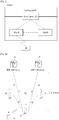
- FIG. 1 is a view schematically illustrating a network structure of an E-UMTS as an exemplary radio communication system.
- An Evolved Universal Mobile Telecommunications System (E-UMTS) is an advanced version of a conventional Universal Mobile Telecommunications System (UMTS) and basic standardization thereof is currently underway in the 3GPP.
- E-UMTS may be generally referred to as a Long Term Evolution (LTE) system.
- LTE Long Term Evolution
- the E-UMTS includes a User Equipment (UE), eNode Bs (eNBs), and an Access Gateway (AG) which is located at an end of the network (E-UTRAN) and connected to an external network.
- the eNBs may simultaneously transmit multiple data streams for a broadcast service, a multicast service, and/or a unicast service.
- One or more cells may exist per eNB.
- the cell is set to operate in one of bandwidths such as 1.25, 2.5, 5, 10, 15, and 20 MHz and provides a downlink (DL) or uplink (UL) transmission service to a plurality of UEs in the bandwidth. Different cells may be set to provide different bandwidths.
- the eNB controls data transmission or reception to and from a plurality of UEs.
- the eNB transmits DL scheduling information of DL data to a corresponding UE so as to inform the UE of a time/frequency domain in which the DL data is supposed to be transmitted, coding, a data size, and hybrid automatic repeat and request (HARQ)-related information.
- HARQ hybrid automatic repeat and request
- the eNB transmits UL scheduling information of UL data to a corresponding UE so as to inform the UE of a time/frequency domain which may be used by the UE, coding, a data size, and HARQ-related information.
- An interface for transmitting user traffic or control traffic may be used between eNBs.
- a core network (CN) may include the AG and a network node or the like for user registration of UEs.
- the AG manages the mobility of a UE on a tracking area (TA) basis.
- One TA includes a plurality of cells.
- WCDMA wideband code division multiple access
- next-generation RAT which takes into account such Enhanced Mobile BroadBand (eMBB) transmission, and ultra-reliable and low latency communication (URLLC) transmission, is being discussed.
- eMBB Enhanced Mobile BroadBand
- URLLC ultra-reliable and low latency communication
- WO 2019/062899 A1 represents prior art according to Art. 54(3) EPC and discloses a bandwidth adaptation for wideband carrier.
- a UE is described to start a BWP timer upon detecting one or more BWP timer starting triggering events, resets the BWP timer upon detecting BWP resetting triggering events, and switches to the default BWP upon expiration of the BWP timer, wherein the BWP timer starting triggering events comprises decoding a command to switch away from the default BWP, the detection of end of DL data transmission in DRX mode.
- the document (“Remaining issues on bandwidth part", 3GPP DRAFT, R1-1717077, XP051340268 ) outlines issues on an initial active BWP, a BWP configuration, an active BWP operation, a bandwidth adaptation and a common PRB indexing.
- the document (“ HARQ process ID and timer for SPS", 3GPP DRAFT, R2-1710959, XP051342917 ) outlines a HARQ process and a timer issue for SPS.
- the document (“ Impact of Bandwidth Parts on SPS Scheduling", 3GPP DRAFT, R2-1711289, XP051343283 ) outlines an SPS procedure when a UE is configured with multiple bandwidth parts.
- the document (“ On Bandwidth Part Operation", 3GPP DRAFT, R1-1717675, XP051352728 ) outlines issues including BWP activation/deactivation, a relationship between CA and BWP, a BWP configuration, a timer-based mechanism, a common PRB indexing and RRM/CSI measurements and SRS transmission.
- An object of the present invention devised to solve the problem lies in a method and device for handling for BWP operation in wireless communication system.
- the SPS can be configured to a UE.
- the DL BWP can be switched by DL or UL scheduling via DCI or BWP inactivity timer related to the DL BWP expiry.
- the UE can periodically use the SPS resource for DL data reception or UL data transmission without explicit DL/UL scheduling grant if Semi-Persistent Scheduling is enabled by RRC.
- the UE may not use a configured UL SPS resource if the MAC entity is configured to skip the uplink TX SPS resource and the MAC PDU includes only the MAC CE for padding BSR or periodic BSR with zero MAC SDUs.
- the UE may not receive a MAC PDU on the configured DL SPS resource if the network skips the configured DL SPS resource. In this condition, if there is no MAC PDU transmitted or received on the uplink grant or the downlink assignment, the configured DL/UL SPS resources are really not used.
- the UE restarts the BWP inactivity timer to the initial value only when it successfully decodes a DCI to schedule PDSCH(s) in its active DL BWP (or its active DL/UL BWP pair).
- the UE can receive or transmit a MAC PDU on a configured DL/UL SPS resource without the explicit DL/UL scheduling information via DCI, but the UE does not restart the BWP inactivity timer.
- the UE may switch to the default DL BWP by the BWP inactivity timer expiry although a UE is receiving a DL SPS data on the active DL BWP.
- This problem occurs because the UE doesn't restart the BWP inactivity timer considering the SPS resource, which is used without DCI, on the active BWP other than the default DL BWP.
- the UE In order for a UE to successfully perform the SPS operation in wider bandwidth cell, the UE should consider the impact of the BWP inactivity timer on the SPS operation which a UE transmits or receives a SPS data without DCI. From this point of view, it is desirable that the BWP configured with the SPS resource should always be active while the SPS operation is active. According to the present invention, when data is transmitted or received using the SPS resource, the DL BWP is not switched without notice, thereby reducing data loss.
- Universal mobile telecommunications system is a 3rd Generation (3G) asynchronous mobile communication system operating in wideband code division multiple access (WCDMA) based on European systems, global system for mobile communications (GSM) and general packet radio services (GPRS).
- 3G 3rd Generation
- WCDMA wideband code division multiple access
- GSM global system for mobile communications
- GPRS general packet radio services
- LTE long-term evolution
- 3GPP 3rd generation partnership project
- the 3GPP LTE is a technology for enabling high-speed packet communications. Many schemes have been proposed for the LTE objective including those that aim to reduce user and provider costs, improve service quality, and expand and improve coverage and system capacity.
- the 3G LTE requires reduced cost per bit, increased service availability, flexible use of a frequency band, a simple structure, an open interface, and adequate power consumption of a terminal as an upper-level requirement.
- LTE long term evolution
- LTE-A LTE-advanced
- the embodiments of the present invention are applicable to any other communication system corresponding to the above definition.
- the embodiments of the present invention are described based on a frequency division duplex (FDD) scheme in the present specification, the embodiments of the present invention may be easily modified and applied to a half-duplex FDD (H-FDD) scheme or a time division duplex (TDD) scheme.
- FDD frequency division duplex
- H-FDD half-duplex FDD
- TDD time division duplex
- FIG.2a is a block diagram illustrating network structure of an evolved universal mobile telecommunication system (E-UMTS).
- E-UMTS may be also referred to as an LTE system.
- the communication network is widely deployed to provide a variety of communication services such as voice (VoIP) through IMS and packet data.
- VoIP voice
- IMS packet data
- the E-UMTS network includes an evolved UMTS terrestrial radio access network (E-UTRAN), an Evolved Packet Core (EPC) and one or more user equipment.
- the E-UTRAN may include one or more evolved NodeB (eNodeB) 20, and a plurality of user equipment (UE) 10 may be located in one cell.
- eNodeB evolved NodeB
- UE user equipment
- MME mobility management entity
- downlink refers to communication from eNodeB 20 to UE 10
- uplink refers to communication from the UE to an eNodeB.
- UE 10 refers to communication equipment carried by a user and may be also referred to as a mobile station (MS), a user terminal (UT), a subscriber station (SS) or a wireless device.
- MS mobile station
- UT user terminal
- SS subscriber station
- FIG. 2b is a block diagram depicting architecture of a typical E-UTRAN and a typical EPC.
- an eNodeB 20 provides end points of a user plane and a control plane to the UE 10.
- MME/SAE gateway 30 provides an end point of a session and mobility management function for UE 10.
- the eNodeB and MME/SAE gateway may be connected via an S1 interface.
- the eNodeB 20 is generally a fixed station that communicates with a UE 10, and may also be referred to as a base station (BS) or an access point.
- BS base station
- One eNodeB 20 may be deployed per cell.
- An interface for transmitting user traffic or control traffic may be used between eNodeBs 20.
- the MME provides various functions including NAS signaling to eNodeBs 20, NAS signaling security, AS Security control, Inter CN node signaling for mobility between 3GPP access networks, Idle mode UE Reachability (including control and execution of paging retransmission), Tracking Area list management (for UE in idle and active mode), PDN GW and Serving GW selection, MME selection for handovers with MME change, SGSN selection for handovers to 2G or 3G 3GPP access networks, Roaming, Authentication, Bearer management functions including dedicated bearer establishment, Support for PWS (which includes ETWS and CMAS) message transmission.
- the SAE gateway host provides assorted functions including Per-user based packet filtering (by e.g.
- MME/SAE gateway 30 will be referred to herein simply as a "gateway,” but it is understood that this entity includes both an MME and an SAE gateway.
- a plurality of nodes may be connected between eNodeB 20 and gateway 30 via the S1 interface.
- the eNodeBs 20 may be connected to each other via an X2 interface and neighboring eNodeBs may have a meshed network structure that has the X2 interface.
- eNodeB 20 may perform functions of selection for gateway 30, routing toward the gateway during a Radio Resource Control (RRC) activation, scheduling and transmitting of paging messages, scheduling and transmitting of Broadcast Channel (BCCH) information, dynamic allocation of resources to UEs 10 in both uplink and downlink, configuration and provisioning of eNodeB measurements, radio bearer control, radio admission control (RAC), and connection mobility control in LTE_ACTIVE state.
- gateway 30 may perform functions of paging origination, LTE-IDLE state management, ciphering of the user plane, System Architecture Evolution (SAE) bearer control, and ciphering and integrity protection of Non-Access Stratum (NAS) signaling.
- SAE System Architecture Evolution
- NAS Non-Access Stratum
- the EPC includes a mobility management entity (MME), a serving-gateway (S-GW), and a packet data network-gateway (PDN-GW).
- MME mobility management entity
- S-GW serving-gateway
- PDN-GW packet data network-gateway
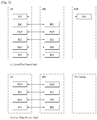
- FIG. 3 is a diagram showing a control plane and a user plane of a radio interface protocol between a UE and an E-UTRAN based on a 3GPP radio access network standard.
- the control plane refers to a path used for transmitting control messages used for managing a call between the UE and the E-UTRAN.
- the user plane refers to a path used for transmitting data generated in an application layer, e.g., voice data or Internet packet data.
- a physical (PHY) layer of a first layer provides an information transfer service to a higher layer using a physical channel.
- the PHY layer is connected to a medium access control (MAC) layer located on the higher layer via a transport channel.
- Data is transported between the MAC layer and the PHY layer via the transport channel.
- Data is transported between a physical layer of a transmitting side and a physical layer of a receiving side via physical channels.
- the physical channels use time and frequency as radio resources.
- the physical channel is modulated using an orthogonal frequency division multiple access (OFDMA) scheme in downlink and is modulated using a single carrier frequency division multiple access (SC-FDMA) scheme in uplink.
- OFDMA orthogonal frequency division multiple access
- SC-FDMA single carrier frequency division multiple access
- the MAC layer of a second layer provides a service to a radio link control (RLC) layer of a higher layer via a logical channel.
- the RLC layer of the second layer supports reliable data transmission.
- a function of the RLC layer may be implemented by a functional block of the MAC layer.
- a packet data convergence protocol (PDCP) layer of the second layer performs a header compression function to reduce unnecessary control information for efficient transmission of an Internet protocol (IP) packet such as an IP version 4 (IPv4) packet or an IP version 6 (IPv6) packet in a radio interface having a relatively small bandwidth.
- IP Internet protocol
- IPv4 IP version 4
- IPv6 IP version 6
- a radio resource control (RRC) layer located at the bottom of a third layer is defined only in the control plane.
- the RRC layer controls logical channels, transport channels, and physical channels in relation to configuration, re-configuration, and release of radio bearers (RBs).
- An RB refers to a service that the second layer provides for data transmission between the UE and the E-UTRAN.
- the RRC layer of the UE and the RRC layer of the E-UTRAN exchange RRC messages with each other.
- One cell of the eNB is set to operate in one of bandwidths such as 1.25, 2.5, 5, 10, 15, and 20 MHz and provides a downlink or uplink transmission service to a plurality of UEs in the bandwidth. Different cells may be set to provide different bandwidths.
- Downlink transport channels for transmission of data from the E-UTRAN to the UE include a broadcast channel (BCH) for transmission of system information, a paging channel (PCH) for transmission of paging messages, and a downlink shared channel (SCH) for transmission of user traffic or control messages.
- BCH broadcast channel
- PCH paging channel
- SCH downlink shared channel
- Traffic or control messages of a downlink multicast or broadcast service may be transmitted through the downlink SCH and may also be transmitted through a separate downlink multicast channel (MCH).
- MCH downlink multicast channel
- Uplink transport channels for transmission of data from the UE to the E-UTRAN include a random access channel (RACH) for transmission of initial control messages and an uplink SCH for transmission of user traffic or control messages.
- Logical channels that are defined above the transport channels and mapped to the transport channels include a broadcast control channel (BCCH), a paging control channel (PCCH), a common control channel (CCCH), a multicast control channel (MCCH), and a multicast traffic channel (MTCH).
- BCCH broadcast control channel
- PCCH paging control channel
- CCCH common control channel
- MCCH multicast control channel
- MTCH multicast traffic channel
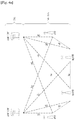
- FIG. 4a is a block diagram illustrating network structure of NG Radio Access Network (NG-RAN) architecture
- FIG. 4b is a block diagram depicting architecture of functional Split between NG-RAN and 5G Core Network (5GC).
- NG-RAN NG Radio Access Network
- 5GC 5G Core Network
- An NG-RAN node is a gNB, providing NR user plane and control plane protocol terminations towards the UE, or an ng-eNB, providing E-UTRA user plane and control plane protocol terminations towards the UE.
- the gNBs and ng-eNBs are interconnected with each other by means of the Xn interface.
- the gNBs and ng-eNBs are also connected by means of the NG interfaces to the 5GC, more specifically to the AMF (Access and Mobility Management Function) by means of the NG-C interface and to the UPF (User Plane Function) by means of the NG-U interface.
- AMF Access and Mobility Management Function
- UPF User Plane Function
- the Xn Interface includes Xn user plane (Xn-U), and Xn control plane (Xn-C).
- the Xn User plane (Xn-U) interface is defined between two NG-RAN nodes.
- the transport network layer is built on IP transport and GTP-U is used on top of UDP/IP to carry the user plane PDUs.
- Xn-U provides non-guaranteed delivery of user plane PDUs and supports the following functions: i) Data forwarding, and ii) Flow control.
- the Xn control plane interface (Xn-C) is defined between two NG-RAN nodes.
- the transport network layer is built on SCTP on top of IP.
- the application layer signalling protocol is referred to as XnAP (Xn Application Protocol).
- the SCTP layer provides the guaranteed delivery of application layer messages.
- point-to-point transmission is used to deliver the signalling PDUs.
- the Xn-C interface supports the following functions: i) Xn interface management, ii) UE mobility management, including context transfer and RAN paging, and iii) Dual connectivity.
- the NG Interface includes NG User Plane (NG-U) and NG Control Plane (NG-C).
- NG-U NG User Plane
- NG-C NG Control Plane
- the NG user plane interface (NG-U) is defined between the NG-RAN node and the UPF.
- the transport network layer is built on IP transport and GTP-U is used on top of UDP/IP to carry the user plane PDUs between the NG-RAN node and the UPF.
- NG-U provides non-guaranteed delivery of user plane PDUs between the NG-RAN node and the UPF.
- the NG control plane interface (NG-C) is defined between the NG-RAN node and the AMF.
- the transport network layer is built on IP transport.
- SCTP is added on top of IP.
- the application layer signalling protocol is referred to as NGAP (NG Application Protocol).
- NGAP NG Application Protocol
- the SCTP layer provides guaranteed delivery of application layer messages.
- IP layer point-to-point transmission is used to deliver the signalling PDUs.
- NG-C provides the following functions: i) NG interface management, ii) UE context management, iii) UE mobility management, iv) Configuration Transfer, and v) Warning Message Transmission.
- the gNB and ng-eNB host the following functions: i) Functions for Radio Resource Management: Radio Bearer Control, Radio Admission Control, Connection Mobility Control, Dynamic allocation of resources to UEs in both uplink and downlink (scheduling), ii) IP header compression, encryption and integrity protection of data, iii) Selection of an AMF at UE attachment when no routing to an AMF can be determined from the information provided by the UE, iv) Routing of User Plane data towards UPF(s), v) Routing of Control Plane information towards AMF, vi) Connection setup and release, vii) Scheduling and transmission of paging messages (originated from the AMF), viii) Scheduling and transmission of system broadcast information (originated from the AMF or O&M), ix) Measurement and measurement reporting configuration for mobility and scheduling, x) Transport level packet marking in the uplink, xi) Session Management, xii) Support of Network Slicing, and xiii) QoS Flow management
- the Access and Mobility Management Function hosts the following main functions: i) NAS signalling termination, ii) NAS signalling security, iii) AS Security control, iv) Inter CN node signalling for mobility between 3GPP access networks, v) Idle mode UE Reachability (including control and execution of paging retransmission), vi) Registration Area management, vii) Support of intra-system and inter-system mobility, viii) Access Authentication, ix) Mobility management control (subscription and policies), x) Support of Network Slicing, and xi) SMF selection.
- the User Plane Function hosts the following main functions: i) Anchor point for Intra-/Inter-RAT mobility (when applicable), ii) External PDU session point of interconnect to Data Network, iii) Packet inspection and User plane part of Policy rule enforcement, iv) Traffic usage reporting, v) Uplink classifier to support routing traffic flows to a data network, vi) QoS handling for user plane, e.g. packet filtering, gating, UL/DL rate enforcement, and vii) Uplink Traffic verification (SDF to QoS flow mapping).
- SDF Uplink Traffic verification
- the Session Management function hosts the following main functions: i) Session Management, ii) UE IP address allocation and management, iii) Selection and control of UP function, iv) Configures traffic steering at UPF to route traffic to proper destination, v) Control part of policy enforcement and QoS, vi) Downlink Data Notification.
- FIG. 5 is a diagram showing a control plane and a user plane of a radio interface protocol between a UE and a NG-RAN based on a 3rd generation partnership project (3GPP) radio access network standard.
- 3GPP 3rd generation partnership project
- the user plane protocol stack contains Phy, MAC, RLC, PDCP and SDAP (Service Data Adaptation Protocol) which is newly introduced to support 5G QoS model.
- the main services and functions of SDAP entity include i) Mapping between a QoS flow and a data radio bearer, and ii) Marking QoS flow ID (QFI) in both DL and UL packets.
- QFI QoS flow ID
- the transmitting SDAP entity may map the SDAP SDU to the default DRB if there is no stored QoS flow to DRB mapping rule for the QoS flow. If there is a stored QoS flow to DRB mapping rule for the QoS flow, the SDAP entity may map the SDAP SDU to the DRB according to the stored QoS flow to DRB mapping rule. And the SDAP entity may construct the SDAP PDU and deliver the constructed SDAP PDU to the lower layers.
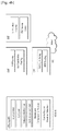
- FIG. 6 is a block diagram of communication devices according to an embodiment of the present invention.
- the apparatus shown in FIG. 6 can be a user equipment (UE) and/or eNB or gNB adapted to perform the above mechanism, but it can be any device for performing the same operation.
- UE user equipment
- one of the communication device 1100 and the communication device 1200 may be a user equipment (UE) and the other one may be a base station.
- one of the communication device 1100 and the communication device 1200 may be a UE and the other one may be another UE.
- one of the communication device 1100 and the communication device 1200 may be a network node and the other one may be another network node.
- the network node may be a base station (BS).
- the network node may be a core network device (e.g. a network device with a mobility management function, a network device with a session management function, and etc.).
- either one of the communication devices 1100, 1200, or each of the communication devices 1100, 1200 may be wireless communication device(s) configured to transmit/receive radio signals to/from an external device, or equipped with a wireless communication module to transmit/receive radio signals to/from an external device.
- the wireless communication module may be a transceiver.
- the wireless communication device is not limited to a UE or a BS, and the wireless communication device may be any suitable mobile computing device that is configured to implement one or more implementations of the present disclosure, such as a vehicular communication system or device, a wearable device, a laptop, a smartphone, and so on.
- a communication device which is mentioned as a UE or BS in the present disclosure may be replaced by any wireless communication device such as a vehicular communication system or device, a wearable device, a laptop, a smartphone, and so on.
- communication devices 1100, 1200 include processors 1111, 1211 and memories 1112, 1212.
- the communication devices 1100 may further include transceivers 1113, 1213 or configured to be operatively connected to transceivers 1113, 1213.
- the processor 1111 and/or 1211 implements functions, procedures, and/or methods disclosed in the present disclosure.
- One or more protocols may be implemented by the processor 1111 and/or 1211.
- the processor 1111 and/or 1211 may implement one or more layers (e.g., functional layers).
- the processor 1111 and/or 1211 may generate protocol data units (PDUs) and/or service data units (SDUs) according to functions, procedures, and/or methods disclosed in the present disclosure.
- the processor 1111 and/or 1211 may generate messages or information according to functions, procedures, and/or methods disclosed in the present disclosure.
- the processor 1111 and/or 1211 may generate signals (e.g.
- the processor 1111 and/or 1211 may receive signals (e.g. baseband signals) from the transceiver 1113 and/or 1213 connected thereto and obtain PDUs, SDUs, messages or information according to functions, procedures, and/or methods disclosed in the present disclosure.
- the memory of 1112 and/or 1212 is connected to the processor of the network node and stores various types of PDUs, SDUs, messages, information and/or instructions.
- the memory 1112 and/or 1212 may be arranged inside or outside the processor 1111 and/or 1211, respectively, and may be connected the processor 1111 and/or 1211, respectively, through various techniques, such as wired or wireless connections.
- the transceiver 1113 and/or 1213 is connected to the processor 1111 and/or 1211, respectively, and may be controlled by the processor 1111 and/or 1211, respectively, to transmit and/or receive a signal to/from an external device.
- the processor 1111 and/or 1211 may control transceiver 1113 and/or 1213, respectively, to initiate communication and to transmit or receive signals including various types of information or data which are transmitted or received through a wired interface or wireless interface.
- the transceivers 1113, 1213 include a receiver to receive signals from an external device and transmit signals to an external device.
- an antenna facilitates the transmission and reception of radio signals (i.e. wireless signals).
- the transceiver 1113 or 1213 transmits and/or receives a wireless signal such as a radio frequency (RF) signal.
- RF radio frequency
- the transceiver 1113 or 1213 may be referred to as a radio frequency (RF) unit.
- the transceiver 1113 and/or 1213 may forward and convert baseband signals provided by the processor 1111 and/or 1211 connected thereto into radio signals with a radio frequency.
- the transceiver 1113 or 1213 may transmit or receive radio signals containing PDUs, SDUs, messages or information according to functions, procedures, and/or methods disclosed in the present disclosure via a radio interface (e.g. time/frequency resources).
- a radio interface e.g. time/frequency resources
- the transceiver 1113 and/ or 1213 may forward and convert the radio signals to baseband signals for processing by the processor 1111 and/or 1211.
- the radio frequency may be referred to as a carrier frequency.
- the processed signals may be processed according to various techniques, such as being transformed into audible or readable information to be output via a speaker of the UE.
- the processing chip may be a system on chip (SoC).
- SoC system on chip
- the processing chip may include the processor 1111 or 1211 and the memory 1112 or 1212, and may be mounted on, installed on, or connected to the communication device 1100 or 1200.
- the processing chip may be configured to perform or control any one of the methods and/or processes described herein and/or to cause such methods and/or processes to be performed by a communication device which the processing chip is mounted on, installed on, or connected to.
- the memory 1112 or 1212 in the processing chip may be configured to store software codes including instructions that, when executed by the processor, causes the processor to perform some or all of functions, methods or processes discussed in the present disclosure.
- the memory 1112 or 1212 in the processing chip may store or buffer information or data generated by the processor of the processing chip or information recovered or obtained by the processor of the processing chip.
- One or more processes involving transmission or reception of the information or data may be performed by the processor 1111 or 1211 of the processing chip or under control of the processor 1111 or 1211 of the processing chip.
- a transceiver 1113 or 1213 operably connected or coupled to the processing chip may transmit or receive signals containing the information or data under the control of the processor 1111 or 1211 of the processing chip.
- the communication device may include or be equipped with a single antenna or multiple antennas.
- the antenna may be configured to transmit and/or receive a wireless signal to/from another wireless communication device.
- the communication device may further include or be equipped with a power management module, an antenna, a battery, a display, a keypad, a Global Positioning System (GPS) chip, a sensor, a memory device, a Subscriber Identification Module (SIM) card (which may be optional), a speaker and/ or a microphone.
- the UE may include or be equipped with a single antenna or multiple antennas.
- a user may enter various types of information (e.g., instructional information such as a telephone number), by various techniques, such as by pushing buttons of the keypad or by voice activation using the microphone.
- the processor of the UE receives and processes the user's information and performs the appropriate function(s), such as dialing the telephone number.
- data may be retrieved from the SIM card or the memory device to perform the function(s).
- the processor of the UE may receive and process GPS information from a GPS chip to perform functions related to a position or a location of a UE, such as vehicle navigation, a map service, and so on.
- the processor may display these various types of information and data on the display for the user's reference and convenience.
- a sensor may be coupled to the processor of the UE.
- the sensor may include one or more sensing devices configured to detect various types of information including, but not limited to, speed, acceleration, light, vibration, proximity, location, image and so on.
- the processor of the UE may receive and process sensor information obtained from the sensor and may perform various types of functions, such as collision avoidance, autonomous driving and so on.
- Various components e.g., a camera, a Universal Serial Bus (USB) port, etc.
- a camera may be further coupled to the processor of the UE and may be used for various services such as autonomous driving, a vehicle safety service and so on.
- some components e.g., a keypad, a Global Positioning System (GPS) chip, a sensor, a speaker and/or a microphone, may not be implemented in a UE.
- GPS Global Positioning System
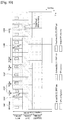
- FIG. 7 is an example for Bandwidth Part (BWP) operation in the prior art.
- BWP Bandwidth Part
- the receive and transmit bandwidth of a UE need not be as large as the bandwidth of the cell and can be adjusted: the width can be ordered to change (e.g. to shrink during period of low activity to save power); the location can move in the frequency domain (e.g. to increase scheduling flexibility); and the subcarrier spacing can be ordered to change (e.g. to allow different services).
- a subset of the total cell bandwidth of a cell is referred to as a Bandwidth Part (BWP) and BA is achieved by configuring the UE with BWP(s) and telling the UE which of the configured BWPs is currently the active one.
- BWP Bandwidth Part
- the gNB configures the UE with UL and DL BWP(s).
- the gNB configures the UE with DL BWP(s) at least (i.e. there may be none in the UL).
- the initial BWP is the BWP used for initial access.
- the initial BWP is the BWP configured for the UE to first operate at SCell activation.
- DL and UL can switch BWP independently.
- DL and UL switch BWP simultaneously. Switching between configured BWPs happens by means of DCI or inactivity timer.
- an inactivity timer is configured for a serving cell, the expiry of the inactivity timer associated to that cell switches the active BWP to a default BWP configured by the network.
- only one UL BWP for each uplink carrier and one DL BWP or only one DL/UL BWP pair can be active at a time in an active serving cell, all other BWPs that the UE is configured with being deactivated.
- the UE On deactivated BWPs, the UE does not monitor the PDCCH, does not transmit on PUCCH, PRACH and UL-SCH.
- the UE When BA is configured, the UE only has to monitor PDCCH on the one active BWP i.e. it does not have to monitor PDCCH on the entire DL frequency of the cell.
- a BWP inactivity timer (independent from the DRX inactivity-timer described above) is used to switch the active BWP to the default one: the timer is restarted upon successful PDCCH decoding and the switch to the default BWP takes place when it expires.
- the DL/UL BWP can be defined as follows:
- the activation/deactivation of DL and UL BWPs can be performed by means of dedicated RRC signalling, DCI or timer.
- Timer-based switching is to support a fallback mechanism to default DL BWP.
- a UE starts the timer when switching to a DL BWP other than the default DL BWP and restarts the timer to the initial value when it successfully decodes a DCI to schedule PDSCH(s) in its active DL BWP. And, the UE switches its active DL BWP to the default DL BWP when the BWP inactivity timer expires. If the active DL/UL BWP has been paired, a UE will switch to default DL/UL BWP pair when the switching condition is met.
- the SPS can be configured to a UE.
- the BWP can be switched by DL or UL scheduling via DCI or BWP inactivity timer expiry.
- the UE can periodically use the SPS resource for DL data reception or UL data transmission without explicit DL/UL scheduling grant if Semi-Persistent Scheduling is enabled by RRC.
- the UE may not use a configured UL SPS resource if the MAC entity is configured to skip the uplink TX SPS resource and the MAC PDU includes only the MAC CE for padding BSR or periodic BSR with zero MAC SDUs.
- the UE may not receive a MAC PDU on the configured DL SPS resource if the network skips the configured DL SPS resource. In this condition, if there is no MAC PDU transmitted or received on the uplink grant or the downlink assignment, the configured DL/UL SPS resources are really not used.
- the UE restarts the BWP inactivity timer to the initial value only when it successfully decodes a DCI to schedule PDSCH(s) in its active DL BWP (or its active DL/UL BWP pair).
- the UE can transmit or receive a MAC PDU on a configured UL/DL SPS resource without the explicit DL/ UL scheduling information via DCI, but the UE does not restart the BWP inactivity timer.
- the BWP inactivity timer associated with BWP 1 is started.
- the SPS resource configuration is activated in BWP1
- the UE is configured to transmit or receive data in the configured SPS resources.
- the problem is from A point.
- BWP inactivity timer expires, BWP 1 should be switched to the default BWP.
- DL data loss is inevitable because the base station cannot know this when it is switched to the default BWP.
- FIG. 8 is a conceptual diagram for handling for BWP operation in wireless communication system according to embodiments of the present invention.
- This embodiment describes from a user equipment perspective.
- This invention proposes that the BWP operation is to restart a timer related to a DL BWP considering the SPS resource. So, as another condition to restart the timer, we can consider that the UE restarts the timer when there is DL SPS resource, or when there is DL SPS resource and the UE receives a MAC PDU on the DL SPS resource.
- the timer can be written by BWP timer or BWP inactivity timer.
- This timer is related to DL BWP other than a default/initial DL BWP.
- the timer may be configured per BWP of the cell, and the timer may be started when a BWP is activated. While the timer related to the DL BWP is running, the UE considers that the DL BWP is activated.
- the UE receives DL/UL SPS configuration information from the network via RRC message (S801).
- the DL/UL SPS configuration information includes at least one of DL/UL SPS resource interval, number of DL/UL HARQ processes, etc.
- the DL/UL SPS configuration information is provided per cell or per BWP.
- the network can dynamically allocate resources to UEs via the C-RNTI on PDCCH(s).
- a UE always monitors the PDCCH(s) in order to find possible assignments when its downlink reception is enabled (activity governed by DRX when configured).
- CA the same C-RNTI applies to all serving cells.
- the network may pre-empt an ongoing PDSCH transmission to one UE with a latency-critical transmission to another UE.
- the network can configure UEs to monitor interrupted transmission indications using INT-RNTI on a PDCCH. If a UE receives the interrupted transmission indication, the UE may assume that no useful information to that UE was carried by the resource elements included in the indication, even if some of those resource elements were already scheduled to this UE.
- the network can allocate downlink resources for the initial HARQ transmissions to UEs: RRC defines the periodicity of the configured downlink assignments while PDCCH addressed to CS-RNTI can either signal and activate the configured downlink assignment, or deactivate it; i.e. a PDCCH addressed to CS-RNTI indicates that the downlink assignment can be implicitly reused according to the periodicity defined by RRC, until deactivated.
- SPS Semi-Persistent Scheduling
- the network can dynamically allocate resources to UEs via the C-RNTI on PDCCH(s).
- a UE always monitors the PDCCH(s) in order to find possible grants for uplink transmission when its downlink reception is enabled (activity governed by DRX when configured).
- CA the same C-RNTI applies to all serving cells.
- the network can allocate uplink resources for the initial HARQ transmissions to UEs.
- Two types of configured uplink grants are defined:
- RRC directly provides the configured uplink grant (including the periodicity).
- RRC defines the periodicity of the configured uplink grant while PDCCH addressed to CS-RNTI can either signal and activate the configured uplink grant, or deactivate it; i.e. a PDCCH addressed to CS-RNTI indicates that the uplink grant can be implicitly reused according to the periodicity defined by RRC, until deactivated.
- a configured uplink grant When a configured uplink grant is active, if the UE cannot find its C-RNTI/CS-RNTI on the PDCCH(s), an uplink transmission according to the configured uplink grant can be made. Otherwise, if the UE finds its C-RNTI/CS-RNTI on the PDCCH(s), the PDCCH allocation overrides the configured uplink grant. Retransmissions other than repetitions are explicitly allocated via PDCCH(s).
- SPS configuration means the MAC entity receives the DL or UL SPS configuration information from RRC signaling when the RRC entity sets up the SPS configuration.
- the SPS operation is NOT activated in MAC entity.
- the SPS configuration means the MAC entity deactivates SPS operation when a PDCCH indicating SPS deactivation is received.
- the SPS configuration is NOT released in the RRC entity. In this condition, the MAC entity considers that there is "a DL or UL SPS configuration".
- the MAC entity activates a SPS operation when a PDCCH indicating SPS activation is received.
- the UE may receive a MAC PDU on a DL SPS resource.
- the UE may transmit a MAC PDU on a UL SPS resource.
- MAC considers that there is periodically "a DL or UL SPS resource".
- the UE receives BWP configuration information from the network via RRC message (S803).
- the BWP configuration information includes at least one of DL/UL carrier frequency, DL/UL bandwidth, a BWP inactivity timer, etc. Multiple BWPs can be configured per cell. A BWP inactivity timer is configured per BWP.
- one or multiple BWP(s) may be configured to a UE via RRC signaling.
- a DL BWP and an UL BWP may be jointly configured as a pair for the unpaired spectrum, or a DL BWP and an UL BWP may be configured separately for the paired spectrum.
- At least one DL BWP and one UL BWP of a cell may be active among the set of configured BWPs for a given time instant.
- the UE receives BWP activation information from the network.
- the BWP activation information indicates which BWP the UE shall activate.
- the UE activates the indicated BWP and starts the corresponding timer related to the indicated BWP (S805). While the timer is running, the UE considers that the corresponding BWP is activated, and the UE can transmit/receive a MAC PDU from/to the BWP.
- the UE monitors PDCCH addressed to SPS-C-RNTI (or CS-RNTI) on the activated BWP (S807).
- the UE When the UE receives PDCCH addressed to SPS-C-RNTI (or CS-RNTI) and if it indicates SPS activation, the UE configures a set of SPS resource using the received SPS configuration information.
- the set of SPS resource includes one or more of SPS resource spanned periodically in the time domain.
- DL SPS resources are configured on the DL BWP and UL SPS resources are configured on a UL BWP related with the DL BWP.
- the UE restarts the timer at the following time points (S809).
- time point when there is SPS resource may be defined to the time value of the TTI with the SPS resource.
- the UE restarts the timer at the time point when there is UL SPS resource and the UE transmits a MAC PDU on the UL SPS resource.
- the MAC PDU not containing a MAC SDU may not trigger restart of the timers.
- the time point when there is UL SPS resource and the UE transmits a MAC PDU on the UL SPS resource may be defined to the time value of the TTI with the UL MAC PDU, or the start time value of the transmission/encoding of the UL MAC PDU on the SPS PUSCH resource, or the end time value of the transmission/encoding of the UL MAC PDU on the SPS PUSCH resource.
- the UE restarts the timer at the time point when there is DL SPS resource and the UE receives a MAC PDU on the DL SPS resource.
- the time point when there is DL SPS resource and the UE receives a MAC PDU on the DL SPS resource may be defined to the time value of the TTI with the DL MAC PDU, or the start time value of the reception/decoding of the DL MAC PDU on the SPS PDSCH resource, or the end time value of the reception/decoding of the DL MAC PDU on the SPS PDSCH resource.
- the time value of a TTI may be based on the subframe/slot/symbol unit, and this may be different depending on the numerology.
- the MAC PDU may contain at least one MAC SDU or MAC CE or MAC header.
- the timer related to the DL BWP is not re-started when the UL data is not transmitted on the UL SPS resource or the DL data is not received in the DL SPS resource.
- the UE switches an active BWP to a default BWP or an initial BWP (S811). It means that the UE deactivates the corresponding DL BWP, and the UE may activate other BWP (i.e., default BWP or initial BWP) (S811).
- the proposed method is implemented by a user equipment (UE), shown in FIG. 6 , but it can be any apparatus for performing the same operation.
- UE user equipment
- the UE (1100 or 1200) may comprises processor (1111 or 1211), Memory (1112 or 1212) and RF module (transceiver; 1113 or 1213).
- the processor (1111 or 1211) is electrically connected with the transceiver (1113 or 1213) and controls it.
- FIG. 6 may represent a UE comprising a processor (1111 or 1211) operably coupled with a memory (1112 or 1212) and configured to start a timer related to a DL BWP, when the UE switches an active BWP for a serving cell to the DL BWP, transmit UL data on one of the UL SPS resources or receive DL data on one of the DL SPS resources via the transceiver (1113 or 1213); and restart the timer related to the DL BWP when the UL data is transmitted on the UL SPS resource or the DL data is received in the DL SPS resource via the transceiver (1113 or 1213).
- a processor (1111 or 1211) operably coupled with a memory (1112 or 1212) and configured to start a timer related to a DL BWP, when the UE switches an active BWP for a serving cell to the DL BWP, transmit UL data on one of the UL SPS resources or receive DL data on one of
- the proposed method is implemented by may be implemented by a processing chip.
- the processing chip may include the processor 1111 or 1211 and the memory 1112 or 1212, and may be mounted on, installed on, or connected to the communication device 1100 or 1200.
- the processing chip may be configured to start a timer related to a DL BWP, when the UE switches an active BWP for a serving cell to the DL BWP, transmit UL data on one of the UL SPS resources or receiving DL data on one of the DL SPS resources via the transmitter or a receiver; and restart the timer related to the DL BWP when the UL data is transmitted on the UL SPS resource or the DL data is received in the DL SPS resource.
- the memory 1112 or 1212 in the processing chip may be configured to store software codes including instructions that, when executed by the processor, causes the processor to perform some or all of functions, methods or processes discussed in the present disclosure.
- the transceiver 1113 or 1213 operably connected or coupled to the processing chip may transmit UL data on one of the UL SPS resources or receive DL data on one of the DL SPS resources under the control of the processor 1111 or 1211 of the processing chip.
- FIG. 6 may represent a UE comprising a processor (110) operably coupled with a memory and configured to start a timer related to a DL BWP, when the UE switches an active BWP for a serving cell to the DL BWP, transmit UL data on one of the UL SPS resources or receiving DL data on one of the DL SPS resource via the transmitter or a receiver; and restart the timer related to the DL BWP when the UL data is transmitted on the UL SPS resource or the DL data is received in the DL SPS resource via the transmitter or receiver (135).
- FIGs. 9 and 10 are examples for handling for BWP operation in wireless communication system according to embodiments of the present invention.
- the following describes the exemplary behavior of the UE according to embodiments of the present invention. These examples assume the following that only one BWP in the cell is active. In other words, while the BWP is active, the timer of the active BWP is running. A DL or UL SPS configuration is configured on the active BWP. And the SPS operation is deactivated.
- the timer can be a BWP inactivity timer.
- FIG. 9 shows an example of a case where the UE restarts the timer of the BWP at the time point when there is DL/UL SPS resource.
- the UE When the UE receives the SPS activation indication on the BWP1, the UE activates the SPS resource configured on the BWP1 (S903).
- the UE can receive or transmit a MAC PDU on the configured DL/UL SPS resource.
- the UE restarts the timer of BWP1 at the time point of the TTI with the DL/UL SPS resource regardless of receiving or transmitting data using the DL/UL SPS resource.
- the UE can start the timer of the BWP1 at the time point of the TTI receiving or transmitting the MAC PDU on the DL/UL SPS resource (S905). Further, the UE can restart the timer of BWP1 at the time point of the TTI with Skipped DL/UL SPS resource (S907).
- the UE does not receive a MAC PDU on a configured DL SPS resource if the network skips a configured DL SPS resource, and for the skipped UL SPS resource, the UE does not transmit a MAC PDU on a configured UL SPS resource if MAC is configured to skip a configured UL SPS resource with skipUplinkTxSPS and there is no UL data.
- NR can periodically allocate semi-persistent uplink resources for the first HARQ transmissions to UEs via RRC but when the UE does not have any data to transmit, it ignores such resources. That is, skipping configured grant (CG) is mandated in NR regardless of CG periodicity. In this condition, MAC considers that there may be 'a skipped DL or UL SPS resource'.
- the UE switches an active BWP from the BWP1 to the default BWP (S909).
- the FIG. 10 shows an example of a case where the UE restarts the timer of the BWP at the time point when there is DL/UL SPS resource and the UE receives or transmits a MAC PDU on the DL or UL SPS resource.
- the UE If the UE receives the SPS activation indication on the BWP1, the UE activates the SPS resource configured on the BWP1 (S1003).
- the UE checks whether a MAC PDU is received or transmitted on the DL/UL SPS resource of BWP1 or not.
- the UE restarts the timer of BWP1 at the time point of the TTI receiving or transmitting the MAC PDU on the DL/UL SPS resource (S1005). If a MAC PDU is not received or transmitted on the DL/UL SPS resource of BWP1, the UE does not restart the timer of BWP1 (S1007).
- the UE When the UE receives the SPS deactivation indication on the BWP1, the UE deactivates the SPS resource configured on the BWP1, but the timer is still running (S1009).
- the UE switches an active BWP from the BWP1 to the default BWP (S1011).
- This invention is an addition to the condition for restarting the BWP inactivity timer. That is, according to the current specification, the UE restarts the BWP inactivity timer to the initial value only when it successfully decodes a DCI to schedule PDSCH(s) in its active DL BWP. That means the UE doesn't restart the BWP inactivity timer considering the SPS resource, which is used without DCI, on the active BWP other than the default BWP. So, we can consider that the UE restarts the BWP inactivity timer when there is DL SPS resource, or when there is DL SPS resource and the UE receives a MAC PDU on the DL SPS resource. Considering the DL SPS skipping, it seems to be desirable for the UE to restart the BWP inactivity timer in the latter case.
- a UE restarts the timer related to the active DL BWP when the UE receives a MAC PDU on the DL SPS resource for the active DL BWP.
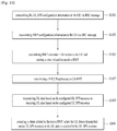
- FIG. 11 is a conceptual diagram for handling for BWP operation in wireless communication system according to embodiments of the present invention.
- the network apparatus means eNB or gNB.
- the network apparatus transmits DL/UL SPS configuration information to the UE via RRC message (S1101).
- the DL/UL SPS configuration information includes at least one of DL/UL SPS resource interval, number of DL/UL HARQ processes, etc.
- the DL/UL SPS configuration information is provided per cell or per BWP.
- the network apparatus transmits BWP configuration information to the UE via RRC message (S1003).
- the BWP configuration information includes at least one of DL/UL carrier frequency, DL/UL bandwidth, a BWP inactivity timer, etc. Multiple BWPs can be configured per cell. A BWP inactivity timer is configured per BWP.
- one or multiple BWP(s) may be configured to a UE via RRC signaling.
- a DL BWP and an UL BWP may be jointly configured as a pair for the unpaired spectrum, or a DL BWP and an UL BWP may be configured separately for the paired spectrum.
- At least one DL BWP and one UL BWP of a cell may be active among the set of configured BWPs for a given time instant.
- the network apparatus transmits BWP activation information to the UE.
- the BWP activation information indicates which BWP the UE shall activate.
- the UE activates the indicated BWP and the corresponding timer is started (S1105). While the timer is running, the network considers that the corresponding BWP is activated, and the network can transmit/receive a MAC PDU from/to the BWP.
- the UE When the network apparatus transmits PDCCH addressed to SPS-C-RNTI (or CS-RNTI) and if it indicates SPS activation, the UE configures a set of SPS resources using the received SPS configuration information (S1107).
- the set of SPS resources includes one or more of SPS resource spanned periodically in the time domain.
- DL SPS resources are configured on the DL BWP and UL SPS resources are configured on a UL BWP related with the DL BWP.
- the network apparatus transmits DL data based on the configured DL SPS resource to the UE or receives UL data based on the configured UL SPS resource from the UE (S1109).
- the network restarts the timer at the time point when there is UL SPS resource, or there is DL SPS resource, or there is UL SPS resource and the network apparatus receives a MAC PDU on the UL SPS resource, or there is DL SPS resource and the network apparatus transmits a MAC PDU on the DL SPS resource (S1111).
- the proposed method is implemented by a network apparatus, shown in FIG. 6 , but it can be any apparatus for performing the same operation.
- the network apparatus may comprises a processor (1111 or 1211), Memory (1112 or 1212), and RF module (transceiver; 1113 or 1213).
- the processor (1111 or 1211) is electrically connected with the transceiver (1113 or 1213) and controls it.
- FIG. 6 may represent a network apparatus comprising a processor (1111 or 1211) operably coupled with the RF module (transceiver; 1113 or 1213) and configured to transmit DL/UL SPS configuration information to the UE, to transmit BWP configuration information to the UE via RRC message, to transmit BWP activation information to the UE, to transmit the PDCCH addressed to SPS-C-RNTI, to transmit DL data based on the configured DL SPS resource or receive UL data based on the configured UL SPS resource via the transceiver (1113 or 1213), and to restart the timer at the time point when the network transmit DL data based on the configured DL SPS resource or receive UL data based on the configured UL SPS resource via the transceiver (1113 or 1213).
- a processor (1111 or 1211) operably coupled with the RF module (transceiver; 1113 or 1213) and configured to transmit DL/UL SPS configuration information to the UE, to transmit BWP configuration information to
- the method according to the embodiments of the present invention may be implemented by one or more Application Specific Integrated Circuits (ASICs), Digital Signal Processors (DSPs), Digital Signal Processing Devices (DSPDs), Programmable Logic Devices (PLDs), Field Programmable Gate Arrays (FPGAs), processors, controllers, microcontrollers, or microprocessors, etc.
- ASICs Application Specific Integrated Circuits
- DSPs Digital Signal Processors
- DSPDs Digital Signal Processing Devices
- PLDs Programmable Logic Devices
- FPGAs Field Programmable Gate Arrays
- processors controllers, microcontrollers, or microprocessors, etc.
- the method according to the embodiments of the present invention may be implemented in the form of modules, procedures, functions, etc. performing the above-described functions or operations.
- Software code may be stored in a memory unit and executed by a processor.
- the memory unit may be located at the interior or exterior of the processor and may transmit and receive data to and from the processor via various known means.
Landscapes
- Engineering & Computer Science (AREA)
- Signal Processing (AREA)
- Computer Networks & Wireless Communication (AREA)
- Mobile Radio Communication Systems (AREA)
- Computer Security & Cryptography (AREA)
Claims (14)
- Ein Verfahren für ein drahtloses Kommunikationsgerät, das in einem drahtlosen Kommunikationssystem betrieben wird, wobei das Verfahren umfasst:Starten eines Timers, der sich auf einen Downlink, DL, Bandbreitenteil, BWP, bezieht, basierend auf einem aktiven BWP für eine bedienende Zelle, die auf den DL BWP umgeschaltet wird;Übertragen von Uplink, UL, -Daten auf einer der UL semi-persistenten Scheduling, SPS, -Ressourcen, die in einem UL BWP konfiguriert sind, der sich auf den DL BWP bezieht; undNeustarten des Timers, der sich auf den DL BWP bezieht, basierend auf den UL-Daten, die auf der UL SPS-Ressource übertragen werden.
- Das Verfahren nach Anspruch 1, ferner umfassend:Empfangen von Informationen bezüglich der SPS-Ressourcenkonfiguration für UL über ein Radio Resource Control, RRC, -Signal von einem Netzwerk; undKonfigurieren einer oder mehrerer UL SPS-Ressourcen auf dem UL BWP basierend auf den Informationen, die sich auf die SPS-Ressourcenkonfiguration für UL beziehen.
- Verfahren nach Anspruch 2, wobei die Informationen, die sich auf die SPS-Ressourcenkonfiguration für UL beziehen, mindestens eines von einem SPS-Ressourcenintervall für UL oder eine Anzahl von Hybrid-ARQ, HARQ, -Prozessen für UL umfassen.
- Verfahren nach Anspruch 1, wobei der DL BWP kein Standard-DL BWP oder ein anfänglicher DL BWP ist.
- Verfahren nach Anspruch 1, wobei während der Laufzeit des auf den DL BWP bezogenen Timers der DL BWP als aktiv betrachtet wird.
- Verfahren nach Anspruch 1, wobei basierend auf dem Ablauf des Timers, der sich auf die DL BWP bezieht, die aktive BWP von dem DL BWP auf einen Standard-BWP oder einen anfänglichen BWP umgeschaltet wird.
- Verfahren nach Anspruch 1, wobei der Timer, der sich auf den DL BWP bezieht, nicht neu gestartet wird, basierend darauf, dass die UL-Daten nicht auf der UL SPS-Ressource übertragen werden.
- Ein drahtloses Kommunikationsgerät (1200), die in einem drahtlosen Kommunikationssystem arbeitet, wobei das drahtlose Kommunikationsgerät (1200) umfasst:eine Speichereinheit (1212); undeinen Prozessor (1211), der betriebsfähig mit der Speichereinheit (1212) gekoppelt ist und konfiguriert ist, um:einen Timer zu starten, der sich auf einen Downlink, DL, Bandbreitenteil, BWP, bezieht, basierend auf einem aktiven BWP für eine bedienende Zelle, die auf den DL BWP umgeschaltet wird,Uplink, UL, -Daten auf eine von UL semi-persistent scheduling, SPS, - Ressourcen, die in einem UL BWP konfiguriert sind, der sich auf den DL BWP bezieht, zu übertragen, undden Timer, der sich auf den DL BWP bezieht, basierend auf den UL-Daten, die auf der UL SPS-Ressource übertragen werden, neu zu starten.
- Das drahtlose Kommunikationsgerät (1200) nach Anspruch 8, wobei der Prozessor (1211) ferner konfiguriert ist, um: Informationen zu empfangen, die sich auf die SPS-Ressourcenkonfiguration für UL über ein Funkressourcensteuerungs, RRC, - Signal von einem Netzwerk beziehen, und eine oder mehrere UL SPS-Ressourcen auf dem UL BWP basierend auf den Informationen zu konfigurieren, die sich auf die SPS-Ressourcenkonfiguration für UL beziehen.
- Das drahtlose Kommunikationsgerät (1200) nach Anspruch 9, wobei die Informationen bezüglich der SPS-Ressourcenkonfiguration für UL mindestens eines von einem SPS-Ressourcenintervallen für UL oder eine Anzahl von Hybrid-ARQ, HARQ, - Prozessen für UL umfassen.
- Das drahtlose Kommunikationsgerät (1200) nach Anspruch 8, wobei der DL BWP kein Standard-DL BWP oder ein anfänglicher DL BWP ist.
- Das drahtlose Kommunikationsgerät (1200) nach Anspruch 8, wobei der Prozessor (1211), während der auf den DL BWP bezogene Timer läuft, davon ausgeht, dass der DL BWP aktiviert ist.
- Das drahtlose Kommunikationsgerät (1200) nach Anspruch 8, wobei der Prozessor (1211) basierend auf dem Ablauf des Timers, der sich auf den DL BWP bezieht, einen aktiven BWP von dem DL BWP auf einen Standard-BWP oder einen anfänglichen BWP umschaltet.
- Drahtloses Kommunikationsgerät (1200) nach Anspruch 8, wobei der auf den DL BWP bezogene Timer nicht neu gestartet wird, basierend auf den UL-Daten, die nicht auf der UL SPS-Ressource übertragen werden.
Applications Claiming Priority (2)
| Application Number | Priority Date | Filing Date | Title |
|---|---|---|---|
| US201762580443P | 2017-11-01 | 2017-11-01 | |
| PCT/KR2018/012468 WO2019088531A1 (en) | 2017-11-01 | 2018-10-22 | Method for handling for bandwidth part operation in wireless communication system and a device therefor |
Publications (3)
| Publication Number | Publication Date |
|---|---|
| EP3662709A1 EP3662709A1 (de) | 2020-06-10 |
| EP3662709A4 EP3662709A4 (de) | 2020-07-22 |
| EP3662709B1 true EP3662709B1 (de) | 2021-06-30 |
Family
ID=66243496
Family Applications (1)
| Application Number | Title | Priority Date | Filing Date |
|---|---|---|---|
| EP18826167.1A Active EP3662709B1 (de) | 2017-11-01 | 2018-10-22 | Verfahren zur handhabung eines bandbreitenteilbetriebs in einem drahtloskommunikationssystem und vorrichtung dafür |
Country Status (6)
| Country | Link |
|---|---|
| US (2) | US10966229B2 (de) |
| EP (1) | EP3662709B1 (de) |
| JP (1) | JP6953615B2 (de) |
| KR (1) | KR102078372B1 (de) |
| CN (1) | CN110463316B (de) |
| WO (1) | WO2019088531A1 (de) |
Families Citing this family (24)
| Publication number | Priority date | Publication date | Assignee | Title |
|---|---|---|---|---|
| WO2019088531A1 (en) | 2017-11-01 | 2019-05-09 | Lg Electronics Inc. | Method for handling for bandwidth part operation in wireless communication system and a device therefor |
| CN113905451B (zh) * | 2017-11-15 | 2022-08-02 | 华为技术有限公司 | 随机接入方法和设备 |
| CN109802781B (zh) * | 2017-11-16 | 2023-01-06 | 夏普株式会社 | 用于处理载波激活的方法及其设备 |
| CN111386745B (zh) | 2017-11-24 | 2023-08-29 | 鸿颖创新有限公司 | 在部分带宽切换操作中处理随机存取程序的方法和相关装置 |
| JP6630422B2 (ja) * | 2017-12-13 | 2020-01-15 | 華碩電腦股▲ふん▼有限公司 | 無線通信システムにおけるランダムアクセス手順中のbwp不活性タイマを処理する方法及び装置 |
| US11357051B2 (en) * | 2017-12-21 | 2022-06-07 | Samsung Electronics Co., Ltd. | System and method of handling bandwidth part inactivity timer |
| CN110035481A (zh) * | 2018-01-11 | 2019-07-19 | 华为技术有限公司 | 定时器的处理方法和终端设备 |
| US11057940B2 (en) * | 2018-04-30 | 2021-07-06 | Samsung Electronics Co., Ltd. | Apparatus and method of transmitting and receiving message 3 protocol data unit |
| TWI708517B (zh) * | 2018-05-06 | 2020-10-21 | 南韓商Lg電子股份有限公司 | 用於傳輸和接收下行鏈路資料的方法及裝置 |
| JP7197297B2 (ja) * | 2018-07-17 | 2022-12-27 | シャープ株式会社 | 基地局装置、端末装置、および、通信方法 |
| CA3141346A1 (en) | 2019-06-20 | 2020-12-24 | Shuqiang Xia | Methods, apparatus and systems for switching between bandwidth parts |
| US20230048976A1 (en) * | 2020-01-20 | 2023-02-16 | Beijing Xiaomi Mobile Software Co., Ltd. | Data transmission method and apparatus, communication device, and storage medium |
| KR20220137001A (ko) * | 2020-02-04 | 2022-10-11 | 엘지전자 주식회사 | 무선 통신 시스템에서 휴면 대역폭 부분의 자동 변경을 위한 방법 및 장치 |
| CN118714661A (zh) * | 2020-06-16 | 2024-09-27 | 展讯通信(上海)有限公司 | 一种多播业务数据接收方法及通信装置 |
| US11832244B2 (en) * | 2020-07-09 | 2023-11-28 | Qualcomm Incorporated | Timers and uplink skipping |
| US12177857B2 (en) * | 2020-08-06 | 2024-12-24 | Qualcomm Incorporated | Bandwidth part (BWP) configuration with a shared partial configuration for non-terrestrial networks (NTNs) |
| EP4209019A2 (de) * | 2020-09-02 | 2023-07-12 | Toyota Jidosha Kabushiki Kaisha | Multicast- und broadcastkonfigurationssignalisierung |
| EP4118862B1 (de) * | 2020-10-16 | 2024-12-25 | Ofinno, LLC | Bandbreitenteil für multicast- und broadcastdienste |
| WO2022082661A1 (en) | 2020-10-22 | 2022-04-28 | Nokia Shanghai Bell Co., Ltd. | Frequency domain resource allocation for multicast traffic |
| KR20230125052A (ko) * | 2020-12-28 | 2023-08-28 | 삼성전자주식회사 | 유니캐스트 및 멀티캐스트/브로드캐스트 서비스를 지원하는무선 통신 시스템에서의 자원 할당 및 동작을 위한 방법 및 장치 |
| US20240179693A1 (en) * | 2021-03-17 | 2024-05-30 | Beijing Xiaomi Mobile Software Co., Ltd. | Bandwidth part configuration method, bandwidth part configuration apapratus, and storage medium |
| CN119255308A (zh) * | 2021-11-05 | 2025-01-03 | 北京小米移动软件有限公司 | Bwp回退方法、装置、设备及存储介质 |
| CN114586450B (zh) * | 2022-01-20 | 2025-08-12 | 北京小米移动软件有限公司 | 切换bwp的方法、装置、通信设备及存储介质 |
| FR3147920A1 (fr) * | 2023-04-13 | 2024-10-18 | Orange | Procédés de configuration et de communication, entité d’un réseau de télécommunications et équipement utilisateur |
Family Cites Families (20)
| Publication number | Priority date | Publication date | Assignee | Title |
|---|---|---|---|---|
| EP2131517A3 (de) * | 2008-06-03 | 2010-01-20 | Innovative Sonic Limited | Verfahren und Vorrichtung zur Verbesserung der HARQ-Uplink-Übertragung |
| WO2012044082A1 (ko) * | 2010-09-29 | 2012-04-05 | 엘지전자 주식회사 | 시간 분할 듀플렉스 시스템에서 복수의 수신 확인 정보 전송 방법 및 장치 |
| WO2014021631A1 (ko) * | 2012-07-31 | 2014-02-06 | 엘지전자 주식회사 | 하향링크 신호 수신 방법 및 사용자기기와, 하향링크 신호 전송 방법 및 기지국 |
| US10193608B2 (en) * | 2014-07-16 | 2019-01-29 | Lg Electronics Inc. | Method for transmitting/receiving channel state information in wireless communication system and device therefor |
| US20160119969A1 (en) * | 2014-10-24 | 2016-04-28 | Qualcomm Incorporated | Mac enhancements for concurrent legacy and ecc operation |
| US9888465B2 (en) * | 2015-04-06 | 2018-02-06 | Samsung Electronics Co., Ltd. | Codeword determination for acknowledgement information |
| US10687319B2 (en) * | 2016-08-08 | 2020-06-16 | Comcast Cable Communications, Llc | Group power control for a secondary cell |
| PL3419363T3 (pl) * | 2016-08-12 | 2021-11-15 | Beijing Xiaomi Mobile Software Co., Ltd. | Okresowe przydzielanie zasobów w sieci bezprzewodowej oraz urządzenie |
| US10750532B2 (en) * | 2016-12-07 | 2020-08-18 | Ofinno, Llc | Semi-persistent scheduling transmission selection |
| EP3563489B1 (de) * | 2016-12-27 | 2022-06-15 | 5G IP Holdings LLC | Verfahren zur signalisierung von indikatoren des bandbreitenteils (bwp) und funkkommunikationsausrüstung damit |
| CN111034270B (zh) * | 2017-08-10 | 2021-10-22 | 三星电子株式会社 | 支持多带宽部分的载波的系统信息发送和接收的设备和方法 |
| US11178012B2 (en) * | 2017-09-06 | 2021-11-16 | Apple Inc. | Configuration schemes for secondary cell, bandwidth part and physical resource block indexing |
| US10567143B2 (en) * | 2017-09-27 | 2020-02-18 | Yeongmoon SON | Method and apparatus to receive and transmit data in a mobile communication system |
| US20190044689A1 (en) * | 2017-09-28 | 2019-02-07 | Intel IP Corporation | Bandwidth part signaling and measurement handling |
| US10594468B2 (en) | 2017-09-29 | 2020-03-17 | Mediatek Inc. | Efficient bandwidth adaptation for a wideband carrier |
| CA3022159C (en) * | 2017-10-26 | 2026-01-13 | Ofinno, Llc | Activation and deactivation of configured grant |
| EP3568946B1 (de) * | 2017-10-26 | 2025-03-19 | Ofinno, LLC | Inaktivitätstimer für bandbreitenteil |
| CN109729590A (zh) * | 2017-10-31 | 2019-05-07 | 华硕电脑股份有限公司 | 无线通信系统中改善启动小区的功率消耗的方法和设备 |
| WO2019088531A1 (en) | 2017-11-01 | 2019-05-09 | Lg Electronics Inc. | Method for handling for bandwidth part operation in wireless communication system and a device therefor |
| CA3023709A1 (en) * | 2017-11-09 | 2019-05-09 | Comcast Cable Communications, Llc | Csi transmission with multiple bandwidth parts |
-
2018
- 2018-10-22 WO PCT/KR2018/012468 patent/WO2019088531A1/en not_active Ceased
- 2018-10-22 EP EP18826167.1A patent/EP3662709B1/de active Active
- 2018-10-22 CN CN201880022994.3A patent/CN110463316B/zh active Active
- 2018-10-22 JP JP2020503244A patent/JP6953615B2/ja active Active
- 2018-10-23 KR KR1020180126546A patent/KR102078372B1/ko active Active
- 2018-11-01 US US16/178,475 patent/US10966229B2/en active Active
-
2021
- 2021-03-03 US US17/191,016 patent/US11683797B2/en active Active
Also Published As
| Publication number | Publication date |
|---|---|
| US10966229B2 (en) | 2021-03-30 |
| EP3662709A4 (de) | 2020-07-22 |
| CN110463316B (zh) | 2023-05-12 |
| EP3662709A1 (de) | 2020-06-10 |
| KR102078372B1 (ko) | 2020-02-17 |
| JP6953615B2 (ja) | 2021-10-27 |
| US20190132855A1 (en) | 2019-05-02 |
| KR20190049476A (ko) | 2019-05-09 |
| CN110463316A (zh) | 2019-11-15 |
| US11683797B2 (en) | 2023-06-20 |
| JP2020516207A (ja) | 2020-05-28 |
| WO2019088531A1 (en) | 2019-05-09 |
| US20210195617A1 (en) | 2021-06-24 |
Similar Documents
| Publication | Publication Date | Title |
|---|---|---|
| US11683797B2 (en) | Method for handling for bandwidth part operation in wireless communication system and a device therefor | |
| EP3666019B1 (de) | Verfahren zur handhabung von vorkonfigurierten benutzergeräteressourcen auf der grundlage eines lbt-verfahrens in einem drahtlosen kommunikationssystem und vorrichtung dafür | |
| US20200288502A1 (en) | Method for performing a random access procedure in bandwidth part (bwp) operation in wireless communication system and a device therefor | |
| US10912108B2 (en) | Method for performing sidelink transmission prioritized over the uplink transmission in wireless communication system and a device therefor | |
| EP3281479B1 (de) | Verfahren zur durchführung von pdcch-überwachung in einer trägeraggregation mit mindestens einer scell, die in einem unlizenzierten spektrum operiert, und vorrichtung dafür | |
| EP3659355B1 (de) | Verfahren zur handhabung eines prohibit-timers zur übertragung einer rrc-nachricht im zusammenhang mit der einschränkung einer ue-fähigkeit in einem drahtloskommunikationssystem und vorrichtung dafür | |
| US11219029B2 (en) | Method for performing semi-persistent scheduling (SPS) activation in multiple SPS resources in wireless communication system and a device therefor | |
| EP3379894B1 (de) | Verfahren zum Zählen eines diskontinuierlichen Empfangszeitgebers (DRX) in einem Trägeraggregationssystem und Vorrichtung dafür | |
| US20200396044A1 (en) | Method for switching a bandwidth part (bwp) for configured ul resources in wireless communication system and a device therefor | |
| US9894610B2 (en) | Method for monitoring on durations in a wireless communication system and a device therefor | |
| WO2014157829A1 (en) | Method for informing identification of a ue and device therefor | |
| US20200170045A1 (en) | Method for performing a random access procedure in wireless communication system and a device therefor | |
| US20200170035A1 (en) | Method for performing a lcp procedure in wireless communication system and a device therefor | |
| EP3603172B1 (de) | Verfahren zur übertragung eines mac-ce in verschiedenen tti-leitungen in einem drahtloskommunikationssystem und vorrichtung dafür | |
| US11363624B2 (en) | Method for receiving DL data on SPS resources in wireless communication system and a device therefor | |
| US20200107375A1 (en) | Method for performing a random access procedure in wireless communication system and a device therefor | |
| US10491363B2 (en) | Method for transmitting a data in a communication system and device therefor | |
| US11374702B2 (en) | Method for semi-persistent scheduling transmission using HARQ process identifiers in wireless communication system and a device therefor | |
| US11387947B2 (en) | Method for performing an adaptive bundling transmission in wireless communication system and a device therefor | |
| EP3689078B1 (de) | Gegen kollisionen auf einer gemeinsam genutzten uplink-ressource in einem drahtlosen kommunikationssystem robustes verfahren zur übertragung von uplink-daten und vorrichtung dafür | |
| WO2015037835A1 (en) | Random access procedures in a wireless network employing tdd scheme | |
| WO2014157828A1 (en) | Method for configuring a receiver bandwidth and device therefor |
Legal Events
| Date | Code | Title | Description |
|---|---|---|---|
| STAA | Information on the status of an ep patent application or granted ep patent |
Free format text: STATUS: UNKNOWN |
|
| STAA | Information on the status of an ep patent application or granted ep patent |
Free format text: STATUS: THE INTERNATIONAL PUBLICATION HAS BEEN MADE |
|
| PUAI | Public reference made under article 153(3) epc to a published international application that has entered the european phase |
Free format text: ORIGINAL CODE: 0009012 |
|
| STAA | Information on the status of an ep patent application or granted ep patent |
Free format text: STATUS: REQUEST FOR EXAMINATION WAS MADE |
|
| 17P | Request for examination filed |
Effective date: 20190109 |
|
| AK | Designated contracting states |
Kind code of ref document: A1 Designated state(s): AL AT BE BG CH CY CZ DE DK EE ES FI FR GB GR HR HU IE IS IT LI LT LU LV MC MK MT NL NO PL PT RO RS SE SI SK SM TR |
|
| AX | Request for extension of the european patent |
Extension state: BA ME |
|
| A4 | Supplementary search report drawn up and despatched |
Effective date: 20200623 |
|
| RIC1 | Information provided on ipc code assigned before grant |
Ipc: H04W 72/04 20090101AFI20200617BHEP |
|
| GRAP | Despatch of communication of intention to grant a patent |
Free format text: ORIGINAL CODE: EPIDOSNIGR1 |
|
| STAA | Information on the status of an ep patent application or granted ep patent |
Free format text: STATUS: GRANT OF PATENT IS INTENDED |
|
| DAV | Request for validation of the european patent (deleted) | ||
| DAX | Request for extension of the european patent (deleted) | ||
| INTG | Intention to grant announced |
Effective date: 20210209 |
|
| RIN1 | Information on inventor provided before grant (corrected) |
Inventor name: LEE, SUNYOUNG Inventor name: YI, SEUNGJUNE Inventor name: LEE, EUNJONG Inventor name: LEE, GYEONGCHEOL |
|
| GRAS | Grant fee paid |
Free format text: ORIGINAL CODE: EPIDOSNIGR3 |
|
| GRAA | (expected) grant |
Free format text: ORIGINAL CODE: 0009210 |
|
| STAA | Information on the status of an ep patent application or granted ep patent |
Free format text: STATUS: THE PATENT HAS BEEN GRANTED |
|
| AK | Designated contracting states |
Kind code of ref document: B1 Designated state(s): AL AT BE BG CH CY CZ DE DK EE ES FI FR GB GR HR HU IE IS IT LI LT LU LV MC MK MT NL NO PL PT RO RS SE SI SK SM TR |
|
| REG | Reference to a national code |
Ref country code: CH Ref legal event code: EP |
|
| REG | Reference to a national code |
Ref country code: DE Ref legal event code: R096 Ref document number: 602018019508 Country of ref document: DE Ref country code: AT Ref legal event code: REF Ref document number: 1407587 Country of ref document: AT Kind code of ref document: T Effective date: 20210715 |
|
| REG | Reference to a national code |
Ref country code: IE Ref legal event code: FG4D |
|
| REG | Reference to a national code |
Ref country code: LT Ref legal event code: MG9D |
|
| PG25 | Lapsed in a contracting state [announced via postgrant information from national office to epo] |
Ref country code: BG Free format text: LAPSE BECAUSE OF FAILURE TO SUBMIT A TRANSLATION OF THE DESCRIPTION OR TO PAY THE FEE WITHIN THE PRESCRIBED TIME-LIMIT Effective date: 20210930 Ref country code: FI Free format text: LAPSE BECAUSE OF FAILURE TO SUBMIT A TRANSLATION OF THE DESCRIPTION OR TO PAY THE FEE WITHIN THE PRESCRIBED TIME-LIMIT Effective date: 20210630 Ref country code: HR Free format text: LAPSE BECAUSE OF FAILURE TO SUBMIT A TRANSLATION OF THE DESCRIPTION OR TO PAY THE FEE WITHIN THE PRESCRIBED TIME-LIMIT Effective date: 20210630 |
|
| REG | Reference to a national code |
Ref country code: NL Ref legal event code: MP Effective date: 20210630 |
|
| REG | Reference to a national code |
Ref country code: AT Ref legal event code: MK05 Ref document number: 1407587 Country of ref document: AT Kind code of ref document: T Effective date: 20210630 |
|
| PG25 | Lapsed in a contracting state [announced via postgrant information from national office to epo] |
Ref country code: GR Free format text: LAPSE BECAUSE OF FAILURE TO SUBMIT A TRANSLATION OF THE DESCRIPTION OR TO PAY THE FEE WITHIN THE PRESCRIBED TIME-LIMIT Effective date: 20211001 Ref country code: LV Free format text: LAPSE BECAUSE OF FAILURE TO SUBMIT A TRANSLATION OF THE DESCRIPTION OR TO PAY THE FEE WITHIN THE PRESCRIBED TIME-LIMIT Effective date: 20210630 Ref country code: NO Free format text: LAPSE BECAUSE OF FAILURE TO SUBMIT A TRANSLATION OF THE DESCRIPTION OR TO PAY THE FEE WITHIN THE PRESCRIBED TIME-LIMIT Effective date: 20210930 Ref country code: SE Free format text: LAPSE BECAUSE OF FAILURE TO SUBMIT A TRANSLATION OF THE DESCRIPTION OR TO PAY THE FEE WITHIN THE PRESCRIBED TIME-LIMIT Effective date: 20210630 Ref country code: RS Free format text: LAPSE BECAUSE OF FAILURE TO SUBMIT A TRANSLATION OF THE DESCRIPTION OR TO PAY THE FEE WITHIN THE PRESCRIBED TIME-LIMIT Effective date: 20210630 |
|
| PG25 | Lapsed in a contracting state [announced via postgrant information from national office to epo] |
Ref country code: ES Free format text: LAPSE BECAUSE OF FAILURE TO SUBMIT A TRANSLATION OF THE DESCRIPTION OR TO PAY THE FEE WITHIN THE PRESCRIBED TIME-LIMIT Effective date: 20210630 Ref country code: EE Free format text: LAPSE BECAUSE OF FAILURE TO SUBMIT A TRANSLATION OF THE DESCRIPTION OR TO PAY THE FEE WITHIN THE PRESCRIBED TIME-LIMIT Effective date: 20210630 Ref country code: SK Free format text: LAPSE BECAUSE OF FAILURE TO SUBMIT A TRANSLATION OF THE DESCRIPTION OR TO PAY THE FEE WITHIN THE PRESCRIBED TIME-LIMIT Effective date: 20210630 Ref country code: CZ Free format text: LAPSE BECAUSE OF FAILURE TO SUBMIT A TRANSLATION OF THE DESCRIPTION OR TO PAY THE FEE WITHIN THE PRESCRIBED TIME-LIMIT Effective date: 20210630 Ref country code: AT Free format text: LAPSE BECAUSE OF FAILURE TO SUBMIT A TRANSLATION OF THE DESCRIPTION OR TO PAY THE FEE WITHIN THE PRESCRIBED TIME-LIMIT Effective date: 20210630 Ref country code: RO Free format text: LAPSE BECAUSE OF FAILURE TO SUBMIT A TRANSLATION OF THE DESCRIPTION OR TO PAY THE FEE WITHIN THE PRESCRIBED TIME-LIMIT Effective date: 20210630 Ref country code: NL Free format text: LAPSE BECAUSE OF FAILURE TO SUBMIT A TRANSLATION OF THE DESCRIPTION OR TO PAY THE FEE WITHIN THE PRESCRIBED TIME-LIMIT Effective date: 20210630 Ref country code: PT Free format text: LAPSE BECAUSE OF FAILURE TO SUBMIT A TRANSLATION OF THE DESCRIPTION OR TO PAY THE FEE WITHIN THE PRESCRIBED TIME-LIMIT Effective date: 20211102 Ref country code: SM Free format text: LAPSE BECAUSE OF FAILURE TO SUBMIT A TRANSLATION OF THE DESCRIPTION OR TO PAY THE FEE WITHIN THE PRESCRIBED TIME-LIMIT Effective date: 20210630 |
|
| PG25 | Lapsed in a contracting state [announced via postgrant information from national office to epo] |
Ref country code: PL Free format text: LAPSE BECAUSE OF FAILURE TO SUBMIT A TRANSLATION OF THE DESCRIPTION OR TO PAY THE FEE WITHIN THE PRESCRIBED TIME-LIMIT Effective date: 20210630 |
|
| REG | Reference to a national code |
Ref country code: DE Ref legal event code: R097 Ref document number: 602018019508 Country of ref document: DE |
|
| PG25 | Lapsed in a contracting state [announced via postgrant information from national office to epo] |
Ref country code: DK Free format text: LAPSE BECAUSE OF FAILURE TO SUBMIT A TRANSLATION OF THE DESCRIPTION OR TO PAY THE FEE WITHIN THE PRESCRIBED TIME-LIMIT Effective date: 20210630 |
|
| PLBE | No opposition filed within time limit |
Free format text: ORIGINAL CODE: 0009261 |
|
| STAA | Information on the status of an ep patent application or granted ep patent |
Free format text: STATUS: NO OPPOSITION FILED WITHIN TIME LIMIT |
|
| REG | Reference to a national code |
Ref country code: CH Ref legal event code: PL |
|
| PG25 | Lapsed in a contracting state [announced via postgrant information from national office to epo] |
Ref country code: AL Free format text: LAPSE BECAUSE OF FAILURE TO SUBMIT A TRANSLATION OF THE DESCRIPTION OR TO PAY THE FEE WITHIN THE PRESCRIBED TIME-LIMIT Effective date: 20210630 |
|
| 26N | No opposition filed |
Effective date: 20220331 |
|
| REG | Reference to a national code |
Ref country code: BE Ref legal event code: MM Effective date: 20211031 |
|
| PG25 | Lapsed in a contracting state [announced via postgrant information from national office to epo] |
Ref country code: MC Free format text: LAPSE BECAUSE OF FAILURE TO SUBMIT A TRANSLATION OF THE DESCRIPTION OR TO PAY THE FEE WITHIN THE PRESCRIBED TIME-LIMIT Effective date: 20210630 |
|
| PG25 | Lapsed in a contracting state [announced via postgrant information from national office to epo] |
Ref country code: LU Free format text: LAPSE BECAUSE OF NON-PAYMENT OF DUE FEES Effective date: 20211022 Ref country code: BE Free format text: LAPSE BECAUSE OF NON-PAYMENT OF DUE FEES Effective date: 20211031 |
|
| PG25 | Lapsed in a contracting state [announced via postgrant information from national office to epo] |
Ref country code: LI Free format text: LAPSE BECAUSE OF NON-PAYMENT OF DUE FEES Effective date: 20211031 Ref country code: CH Free format text: LAPSE BECAUSE OF NON-PAYMENT OF DUE FEES Effective date: 20211031 |
|
| PG25 | Lapsed in a contracting state [announced via postgrant information from national office to epo] |
Ref country code: FR Free format text: LAPSE BECAUSE OF NON-PAYMENT OF DUE FEES Effective date: 20211031 |
|
| PG25 | Lapsed in a contracting state [announced via postgrant information from national office to epo] |
Ref country code: IE Free format text: LAPSE BECAUSE OF NON-PAYMENT OF DUE FEES Effective date: 20211022 |
|
| PG25 | Lapsed in a contracting state [announced via postgrant information from national office to epo] |
Ref country code: LT Free format text: LAPSE BECAUSE OF FAILURE TO SUBMIT A TRANSLATION OF THE DESCRIPTION OR TO PAY THE FEE WITHIN THE PRESCRIBED TIME-LIMIT Effective date: 20210630 |
|
| GBPC | Gb: european patent ceased through non-payment of renewal fee |
Effective date: 20221022 |
|
| PG25 | Lapsed in a contracting state [announced via postgrant information from national office to epo] |
Ref country code: CY Free format text: LAPSE BECAUSE OF FAILURE TO SUBMIT A TRANSLATION OF THE DESCRIPTION OR TO PAY THE FEE WITHIN THE PRESCRIBED TIME-LIMIT Effective date: 20210630 |
|
| PG25 | Lapsed in a contracting state [announced via postgrant information from national office to epo] |
Ref country code: HU Free format text: LAPSE BECAUSE OF FAILURE TO SUBMIT A TRANSLATION OF THE DESCRIPTION OR TO PAY THE FEE WITHIN THE PRESCRIBED TIME-LIMIT; INVALID AB INITIO Effective date: 20181022 |
|
| PG25 | Lapsed in a contracting state [announced via postgrant information from national office to epo] |
Ref country code: GB Free format text: LAPSE BECAUSE OF NON-PAYMENT OF DUE FEES Effective date: 20221022 |
|
| PG25 | Lapsed in a contracting state [announced via postgrant information from national office to epo] |
Ref country code: MK Free format text: LAPSE BECAUSE OF FAILURE TO SUBMIT A TRANSLATION OF THE DESCRIPTION OR TO PAY THE FEE WITHIN THE PRESCRIBED TIME-LIMIT Effective date: 20210630 |
|
| PG25 | Lapsed in a contracting state [announced via postgrant information from national office to epo] |
Ref country code: MT Free format text: LAPSE BECAUSE OF FAILURE TO SUBMIT A TRANSLATION OF THE DESCRIPTION OR TO PAY THE FEE WITHIN THE PRESCRIBED TIME-LIMIT Effective date: 20210630 |
|
| PGFP | Annual fee paid to national office [announced via postgrant information from national office to epo] |
Ref country code: IT Payment date: 20250909 Year of fee payment: 8 |
|
| PG25 | Lapsed in a contracting state [announced via postgrant information from national office to epo] |
Ref country code: TR Free format text: LAPSE BECAUSE OF FAILURE TO SUBMIT A TRANSLATION OF THE DESCRIPTION OR TO PAY THE FEE WITHIN THE PRESCRIBED TIME-LIMIT Effective date: 20210630 |
|
| PGFP | Annual fee paid to national office [announced via postgrant information from national office to epo] |
Ref country code: DE Payment date: 20250908 Year of fee payment: 8 |