EP3662647B1 - Virtualisierte netzwerkfunktionen durch adressraumaggregation - Google Patents
Virtualisierte netzwerkfunktionen durch adressraumaggregation Download PDFInfo
- Publication number
- EP3662647B1 EP3662647B1 EP18760072.1A EP18760072A EP3662647B1 EP 3662647 B1 EP3662647 B1 EP 3662647B1 EP 18760072 A EP18760072 A EP 18760072A EP 3662647 B1 EP3662647 B1 EP 3662647B1
- Authority
- EP
- European Patent Office
- Prior art keywords
- customer edge
- edge router
- data packet
- router
- address
- Prior art date
- Legal status (The legal status is an assumption and is not a legal conclusion. Google has not performed a legal analysis and makes no representation as to the accuracy of the status listed.)
- Active
Links
Images





Classifications
-
- H—ELECTRICITY
- H04—ELECTRIC COMMUNICATION TECHNIQUE
- H04L—TRANSMISSION OF DIGITAL INFORMATION, e.g. TELEGRAPHIC COMMUNICATION
- H04L61/00—Network arrangements, protocols or services for addressing or naming
- H04L61/09—Mapping addresses
- H04L61/25—Mapping addresses of the same type
- H04L61/2503—Translation of Internet protocol [IP] addresses
- H04L61/2592—Translation of Internet protocol [IP] addresses using tunnelling or encapsulation
-
- H—ELECTRICITY
- H04—ELECTRIC COMMUNICATION TECHNIQUE
- H04L—TRANSMISSION OF DIGITAL INFORMATION, e.g. TELEGRAPHIC COMMUNICATION
- H04L45/00—Routing or path finding of packets in data switching networks
- H04L45/74—Address processing for routing
-
- H—ELECTRICITY
- H04—ELECTRIC COMMUNICATION TECHNIQUE
- H04L—TRANSMISSION OF DIGITAL INFORMATION, e.g. TELEGRAPHIC COMMUNICATION
- H04L61/00—Network arrangements, protocols or services for addressing or naming
- H04L61/09—Mapping addresses
- H04L61/25—Mapping addresses of the same type
- H04L61/2503—Translation of Internet protocol [IP] addresses
- H04L61/2514—Translation of Internet protocol [IP] addresses between local and global IP addresses
Definitions
- the present disclosure relates generally to network communications.
- CGN Carrier-grade Network Address Translation
- This disclosure is generally drawn, inter alia, to methods, apparatus, systems, devices, and/or computer program products related to allowing multiple, distributed network nodes to participate in and enable one or more managed services (interchangeably referred to herein as "network functions" or “functions”) that would typically be delivered using a small number of centralized, large scale network appliances.
- a network service provider (interchangeably referred to herein as a "network carrier” or “carrier”) may employ an aggregation layer that includes a small number of centralized network nodes or aggregation nodes.
- the network service provider may place an enterprise customer on one side of the aggregation layer, and the network infrastructure that is outside of the enterprise customer, such as the Internet, on the other side of the aggregation layer.
- the network service provider may direct all network traffic between the enterprise customer and the network infrastructure outside the enterprise customer through the aggregation layer. That is, all network traffic into and out of the carrier network travels through the small number of centralized aggregation nodes in the aggregation layer.
- a carrier may employ a small number of centralized peering routers or provider edge routers (interchangeably referred to herein as "aggregation nodes” or “aggregation routers”) in the aggregation layer, and place the small number of centralized aggregation routers at or near the public edge of the carrier network.
- the carrier may also employ and manage multiple routers (e.g., customer edge routers) at the edge of the carrier network where the enterprise customer connects to the carrier network.
- the customer edge routers may be located at the various location or premises of the enterprise customer.
- the customer edge routers may connect to the provider edge of the carrier, for example, the aggregation routers, and may be the last points of the carrier.
- the carrier may advertise a public address using the aggregation routers, thus directing the network traffic to the carrier network through the aggregation routers.
- the carrier may provide the appropriate routing between the aggregation routers and the customer edge routers. As all network traffic into and out of the carrier network passes through the small number of centralized aggregation routers, the carrier may provide the managed services at the small number of centralized aggregation routers.
- the carrier is also able to control the route of the return network traffic (e.g., get more network traffic to pass through the carrier network).
- the carrier may provide Carrier-grade Network Address Translation (CGN) at the aggregation routers to direct and control the network traffic into and out of the carrier network through the aggregation routers.
- CGN is an approach where the carrier is able to provide the customer edge routers (e.g., the enterprise customer) private addresses, bring the network traffic from the customer edge routers to the small number of aggregation routers, and translate the private network address to public addresses of the aggregation routers (e.g., the public address advertised by the aggregation routers) at the aggregation routers.
- CGN Carrier-grade Network Address Translation
- the aggregation routers may perform a "reverse" translation for the return network traffic to the customer edge routers. This may require the small number of aggregation routers to maintain a very large, and maybe significant amount of state information as the aggregation routers may be providing CGN for a very large number of network addresses (e.g., network nodes). This may present scalability issues. In addition, a failure of an aggregation router may have a significant impact (e.g., affect a very large number of network nodes) as the aggregation router may be serving hundreds or thousands of customers.
- the present disclosure generally describes any number of distributed network nodes participating in and enabling one or more network functions that would typically be delivered using a small number of centralized aggregation nodes.
- multiple customer edge routers may use a combination of distributed processing and address space aggregation across a carrier network domain where a network function is to be provided to deliver the network function in a virtualized manner.
- CGN function will be described as an example of a virtualized network function.
- network functions such as firewalls, content inspection and filtering, customer premises equipment (CPE), and the like, may be similarly provided in a virtualized manner as described herein with respect to CGN.
- Another example of such a network function may include virtual private networking (VPN) and associated address mapping when transporting packets from and/or to one or more VPNs.
- VPN virtual private networking
- a virtualized CGN function may be provided on an architecture that includes an aggregation platform layer, a function endpoint layer, and an aggregated or functional Internet Protocol (IP) address space.
- the aggregation platform layer may include one or more aggregation routers.
- the aggregation platform layer may terminate the tunnels from the function endpoint layer to act as a gateway between an outside network (e.g., the Internet) and the devices performing the virtualized CGN function.
- the aggregation platform layer may also advertise an aggregated IP address space.
- the advertised aggregated IP address space may provide return routability to the function endpoint layer such that the function endpoint layer appears to be on a carrier network that is providing the virtualized CGN function.
- the function endpoint layer may include the devices that perform the Network Address Translation (NAT) to collectively form a virtualized CGN carrier network (e.g., virtualized CGN domain).
- the virtualized CGN carrier network may be accessible through the aggregation platform layer.
- the function endpoint layer may include one or more customer edge routers. Each customer edge router may establish a tunnel to each aggregation router in the aggregation platform layer to establish an overlay network.
- the aggregated IP address space may be assigned to the customer edge routers in the function endpoint layer as individual IP addresses, for example, on the connections facing the carrier network. In instances where a customer edge router resides in multiple carrier networks, the aggregated IP address space may be assigned to the customer edge router as a logical loopback address.
- the aggregated IP address space may be assigned by the carrier, and advertised from the aggregation routers in the aggregation platform layer.
- the agrregated IP address space may be carrier independent.
- the customer edge routers in the function endpoint may reside in any carrier domain (e.g., carrier network), and be logically tied to the carrier that is providing (managing) the virtualized CGN function.
- each aggregation router may advertise an aggregated IP address space.
- the aggregated IP address space includes the IP addresses assigned to the customer edge routers.
- Each customer edge router performs the NAT using its assigned IP address.
- Each customer edge router establishes a tunnel with each aggregation router. Suitable protocols for establishing a tunnel include, by way of example, Generic Routing Encapsulation (GRE), Internet Protocol Security (IPsec), Layer 2 Tunneling Protocol (L2TP), and/or others.
- GRE Generic Routing Encapsulation
- IPsec Internet Protocol Security
- L2TP Layer 2 Tunneling Protocol
- the customer edge router Upon receiving a data packet (e.g., network traffic) that is subject to NAT (e.g., network traffic from the enterprise customer), the customer edge router performs the NAT of the data packet (e.g. using the IP address assigned to the customer edge router), encapsulates the NAT'ed data packet with overlay information of a tunnel to a specific aggregation router, and sends the encapsulated data packet to the specific aggregation router through the tunnel.
- the specific aggregation router may remove the overlay information, maintain a record of the tunnel through which the data packet is received, and forward the de-encapsulated data packet to the specified destination. For example, the specific aggregation router may maintain the record of the tunnel through which the data packet was received in a routing table.
- the customer edge router performs VPN mapping.
- the customer edge router When receiving a data packet from a VPN, when performing the NAT of the data packet, the customer edge router identifies the VPN with which the data packet is associated. Additionally, the customer edge router maintains a Virtual Routing & Forwarding (VRF) table that identifies which addresses are to be routed within the particular VPN. For example, the customer edge router may store a route target for the route distinguishers to identify the VPN.
- the NAT performed on the data packet may address VPN routing such that the specific aggregation router does not store any VPN information.
- Embodiments of the present disclosure may provide an arrangement such that an enterprise may acquire a data link to a provider (e.g., Verizon or Comcast) and may obtain VPN services via the customer edge routers rather than the provider edge router.
- a provider e.g., Verizon or Comcast
- the aggregation router may forward the return data packet to a specific (e.g., correct) customer edge router based on the addressing information in the return data packet.
- the destination address specified in the return data packet may be that of an address in the aggregated IP address space.
- the source and destination addresses in the return data packet may be the "reverse" of the source and destination addresses in the original, NAT'ed data packet. That is, the original, NAT'ed source address is now the destination address in the return data packet, and the original destination address is now the source address in the return data packet.
- the aggregation router may identify a specific customer edge router, and the tunnel established with the specific customer edge router, based on the previously maintained record of the tunnels through which it received the NAT'ed data packets.
- the aggregation router may encapsulate the return data packet with overlay information of the tunnel to the identified customer edge router, and send the encapsulated return data packet to the identified customer edge router through the tunnel.
- the specific customer edge router removes the overlay information, performs a reverse translation (e.g., reverse NAT) of the return data packet, and forwards the de-encapsulated, reverse translated return data packet to the specified destination.
- a reverse translation e.g., reverse NAT
- the customer edge router When the customer edge router receives the return data packet to perform the reverse NAT, the customer edge router additionally performs VPN mapping.
- the NAT table identifies to which VPN the return data packet is directed to.
- the VRF table of that VPN identifies where the return data packet is to be routed within the VPN.
- the architecture provides for construction of a virtual CGN function by allowing each customer edge router to perform the NAT of the network traffic, using the aggregation routers as entry and exit points to the NAT function, and routing the network traffic in an overlay network using tunnels between each customer edge router and the aggregation routers.
- One benefit provided by the architecture is that any scaling issue is greatly minimized. For example, as the scale of the virtual CGN may be limited by the amount of network traffic and/or the number of tunnels that may be supported by any one aggregation router, this scale issue may be readily addressed by clustering customer edge routers around additional aggregation routers.
- each customer edge router maintains the state information for the network traffic NAT performed by the customer edge router.
- the aggregation routers do not maintain any NAT state information.
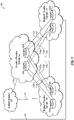
- FIG. 1 illustrates an overview of an environment 100 and devices on which an architecture of the present disclosure may operate, arranged in accordance with at least some embodiments described herein.
- Environment 100 may include a function provider domain 102, network provider domains 104 and 106, and an outside network 108.
- Function provider domain 102, network provider domain 104, and network provider domain 106 may be a carrier network provided and managed by a carrier such as Verizon, AT&T, Sprint, Comcast, and the like.
- Outside network 108 may include any network infrastructure, such as the Internet, one or more connected public networks, and the like, that is external to an enterprise customer.
- Function provider domain 102, network provider domains 104 and 106, and outside network 108 may each be logically connected to the other by communication links 110a-110e.
- Communication links 110a-110e may be interprovider (e.g., intercarrier) links.
- Function provider domain 102 may provide the aggregation platform layer functionality.
- Function provider domain 102 may include a small number of network appliances, such as aggregation routers 102a and 102b. Aggregation routers 102a and 102b may be located or placed at or near the public edge of the carrier network (e.g., function provider domain 102).
- Function provider domain 102 may operate or function as a gateway between network provider domains 104 and 106 and outside network 108.
- Network provider domains 104 and 106 may provide the Network Address Translation (NAT) functionality.
- Network provider domains 104 and 106 may each include multiple network appliances, such as customer edge routers, located or placed at the edge of the carrier network (e.g., network provider domain 104 and network provider domain 106, respectively) where an enterprise customer connects to the carrier network.
- network provider domain 104 may include customer edge routers 104a and 104b located or placed at the enterprise customer edge of the carrier network (e.g., network provider domain 104).
- Network provider domain 106 may include customer edge routers 106a and 106b located or placed at the enterprise customer edge of the carrier network (e.g., network provider domain 106).
- the network provider domain 104 may establish an overlay network with the function provider domain 102.
- each customer edge router 104a, 104b, 106a, and 106b may be configured to establish a tunnel to each aggregation router 102a and 102b in the function provider domain.
- the established tunnels tie or connect the NAT execution locations (e.g., the function execution customer edge routers 104a, 104b, 106a, and 106b) with the aggregation points (e.g., aggregation routers 102a and 102b) to provide a logical reference and connection in an overlay fashion.
- a tunnel 112a may be established between customer edge router 104a and aggregation router 102a
- a tunnel 112b may be established between customer edge router 104a and aggregation router 102b
- a tunnel 112c may be established between customer edge router 104b and aggregation router 102a
- a tunnel 112d may be established between customer edge router 104d and aggregation router 102b
- a tunnel 112e may be established between customer edge router 106a and aggregation router 102a
- a tunnel 112f may be established between customer edge router 106a and aggregation router 102b
- a tunnel 112g may be established between customer edge router 106b and aggregation router 102a
- a tunnel 112h may be established between customer edge router 106d and aggregation router 102b.
- an abstraction mechanism other than tunnels may be used to provide the logical reference and connection between the network provider domain 104 and the function provider domain 102.
- function provider domain 102 and network provider domains 104 and 106 may be provided by a single or same carrier. That is, function provider domain 102 and network provider domains 104 and 106 may be a carrier network provided and managed by a single carrier.
- a carrier such as Verizon to manage its network (e.g., provide managed services including CGN to the enterprise customer).
- Verizon may be able to support both enterprise customer locations with its networks (e.g., network provider domain 104 to service the first enterprise customer location and network provider domain 106 to service the second enterprise customer location). That is, Verizon may have sufficient network circuits to support both enterprise customer locations.
- function provider domain 102 and network provider domains 104 and 106 may be a Verizon network.
- Verizon may place customer edge routers 104a and 104b at the first enterprise customer location, and customer edge routers 106a and 106b at the second enterprise customer location.
- Verizon may manage each customer edge routers 104a, 104b, 106a, and 106b to perform the NAT functionality to provide the virtual CGN. That is, customer edge routers 104a, 104b, 106a, and 106b may be configured to collectively form a virtualized CGN carrier network.
- one or more network provider domains may be provided by a carrier that is different than the carrier providing function provider domain 102. That is, function provider domain 102 may be a first carrier network provided and managed by a first carrier, and one or more network provider domains (e.g., network provider domain 104 and/or network provider domain 106) may be a second carrier network provided and managed by a second carrier.
- Verizon may be able to support the first enterprise customer location but not the second enterprise customer location. That is, Verizon may have the infrastructure (e.g., network circuits) to support the first enterprise customer location, but lack (e.g., not have) the infrastructure to support the second enterprise customer location.
- Verizon may lease the necessary network circuits from a carrier that has the infrastructure to support the second enterprise customer location. For example, assuming that Comcast has the infrastructure to support the second enterprise customer location, Verizon may lease the necessary network circuits from Comcast to support the second enterprise customer location.
- function provider domain 102 and network provider domain 104 may be a Verizon network to service the first customer location
- network provider domain 106 may be a Comcast network to service the second enterprise customer location.
- Verizon is only leasing the Comcast network circuits to support the second enterprise customer location.
- Verizon is managing the enterprise customer networks at both the first enterprise customer location and the second enterprise customer location.
- Verizon may place customer edge routers 104a and 104b at the first enterprise customer location, and customer edge routers 106a and 106b at the second enterprise customer location.
- customer edge routers 106a and 106b are Verizon routers managed by Verizon, customer edge routers 106a and 106b are connected to Comcast network circuits.
- Verizon may manage each customer edge routers 104a, 104b, 106a, and 106b to perform the NAT functionality to provide the virtual CGN. That is, customer edge routers 104a, 104b, 106a, and 106b may be configured to collectively form a virtualized CGN carrier network.
- function provider domain 102 may include a different number of aggregation routers.
- each or both of network provider domains 104 and/or 106 may include any number of customer edge routers, such as hundreds of customer edge routers.
- multiple carriers in addition to the carrier providing the carrier network for the function provider domain may be providing the carrier networks for some of the network provider domains.
- FIG. 2 illustrates an example address space management in the architecture of FIG. 1 , arranged in accordance with at least some embodiments described herein.
- the architecture of FIG. 2 is substantially similar to the architecture of FIG. 1 , with additional details. Those components in FIG. 2 that are labelled identically to components of FIG. 1 will not be described again for the purposes of clarity. More specifically, FIG. 2 illustrates an example assignment of an aggregated IP address space of the aggregation platform layer to the function endpoint layer as individual public IP addresses. The individual public IP addresses are specific IP addresses in the aggregated IP address space.
- a carrier that is providing function provider domain 102 may assign an aggregated IP address space to the aggregation routers (e.g., aggregation routers 102a and 102b) in function provider domain 102.
- the aggregated IP address space may be a block of public IP addresses belonging to the carrier.
- the carrier may assign a specific host IP address from the aggregated IP address space to each customer edge router (e.g., customer edge routers 104a, 104b, 106a, and 106b) the carrier is managing through function provider domain 102.
- Each customer edge router in the function endpoint layer may be configured to perform NAT using the assigned host IP address.
- aggregated IP address space 11.1.1.0/24 may be a block of public IP addresses belonging to Verizon.
- Verizon may assign the block of public IP addresses to aggregation routers 102a and 102b.
- Verizon may distribute the block of public IP addresses, 11.1.1.0/24, to the enterprise customer Verizon is providing managed services to.
- Verizon may assign public IP address 11.1.1.1/32 to customer edge router 104a, public IP address 11.1.1.2/32 to customer edge router 104b, public IP address 11.1.1.3/32 to customer edge router 106a, and public IP address 11.1.1.4/32 to customer edge router 106b.
- Comcast is providing network provider domain 106
- Verizon may assign specific public IP addresses from the aggregated IP address space to customer edge routers 106a and 106b since these routers are being managed by Verizon.
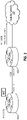
- FIG. 3 illustrates an example address and function assignments of selected devices in the architecture of FIG. 1 , arranged in accordance with at least some embodiments described herein.
- Customer edge router 104a may establish tunnel 112a to aggregation router 102a.
- tunnel 112a may be logically connected to port address 13.1.1.1 at customer edge router 104a, and port address 15.1.1.1 at aggregation router 102a.
- Tunnel 112a provides an overlay.
- Provider edge router 102a may be configured to advertise the aggregated IP address space assigned to function provider domain 102 to the public.
- provider edge router 102 may advertise the IP address prefix 11.1.1.0/24 to outside network 108.
- Customer edge router 104a may be configured to perform NAT of data packets using the specific host IP address assigned to customer edge router 104.
- the specific host IP address is a public IP address included in the aggregated IP address space.
- customer edge router 104a may perform NAT using host IP address 11.1.1.1/32. Performing NAT using its host address and using the overlay to aggregation router 102a allows customer edge router 104a to retain visibility of return network traffic even in instances where the circuit is being provided by a different carrier. That is, the return network traffic is able to come back to customer edge router 104a.
- FIG. 4 is a sequence diagram that illustrates an example network traffic flow, arranged in accordance with at least some embodiments described herein.
- the network traffic flow may be from a source, for example, a client device 402, to a destination, for example, a client device 404.
- Client device 402 may have a private IP address 10.1.1.1, and client device 404 may have a private IP address 12.1.1.1.
- Client device 402 may send or transmit a data packet 406, which specifies a source IP address 10.1.1.1:05 and a destination IP address 12.1.1.1 (e.g., from port :05).
- Data packet 406 may also include other information.
- Customer edge router 104a receives data packet 406 and determines to perform NAT on data packet 406. For example, customer edge router 104a may make a determination to perform NAT based on local configuration and/or one or more applicable policies. Having determined to perform NAT on data packet 406, customer edge router 104a translates the private source IP address 10.1.1.1:05 to public IP address 11.1.1.1, which is the device IP address assigned to customer edge router 104a. The NAT'ed data packet may specify a new source IP address 11.1.1.1 and the destination IP address 12.1.1.1. Customer edge router maintains a record of the mapping of private IP address 10.1.1.1:05 to public IP address 11.1.1.1, for example, in a NAT mapping table.
- the customer edge router 104a maintains a virtual routing and forwarding (VRF) table.
- VRF virtual routing and forwarding
- the enterprise associated with customer edge router 104a may operate multiple VPNs, each with their own VRF.
- the customer edge router 104a Based on which VPN the data packet is received from, the customer edge router 104a creates an entry in the NAT table identifying to which VPN the data packet belongs.
- the data packet 406 may come from VPN_1.
- the customer edge router 104a additionally creates an entry in the VRF table for VPN_1 that identifies that data packets directed to the address 10.1.1.1 are to be out of Interface_1 of the customer edge router 104a.
- a range of addresses may be assigned to a given customer such that one or more VPNs of the customer may be given a specific IP address within the range of addresses.
- the range of addresses may cover the number of VPNs an organization may utilize.
- Customer edge router 104a determines that the NAT'ed data packet is to be sent to aggregation router 102a. For example, customer edge router 104a may select the appropriate aggregation router to receive the NAT'ed data packet based on local configuration and/or one or more applicable policies. Having selected aggregation router 102a, customer edge router 104a encapsulates the NAT'ed data packet with overlay information that corresponds to (e.g., identifies) tunnel 112a. For example, the overlay information may include an overlay header that specifies a source port address of tunnel 112a, 13.1.1.1, and a destination port address of tunnel 112a, 15.1.1.1.
- An encapsulated and NAT'ed data packet 408 may specify a source IP address 11.1.1.1 and a destination IP address 12.1.1.1, and include an overlay header that specifies a source port address 13.1.1.1 and a destination port address 15.1.1.1.
- Customer edge router 104a sends encapsulated and NAT'ed data packet 408 through tunnel 112a to aggregation router 102a.
- Encapsulated and NAT'ed data packet 408 may also include other information.
- Aggregation router 102a may receive encapsulated and NAT'ed data packet 408, for example, at the other end of tunnel 112a. Aggregation router 102a may remove the overlay header, source port address 13.1.1.1 and destination port address 15.1.1.1, from encapsulated and NAT'ed data packet 408 to generate a de-encapsulated data packet 410. De-encapsulated data packet 410 may specify the source IP address 11.1.1.1 and the destination IP address 12.1.1.1. From the overlay header, aggregation router 102a may identify tunnel 112a as the tunnel through which encapsulated and NAT'ed data packet 408 is received.
- Aggregation router 102a may maintain a record that encapsulated and NAT'ed data packet 408 is received through tunnel 112a, for example, in a routing table.
- the record may indicate that IP address 11.1.1.1 (e.g., the source IP address specified in de-encapsulated data packet 410) is routed to IP address 13.1.1.1 (e.g., the source port address specified in the overlay header).
- Aggregation router 102a may use this record to correctly route the return network traffic to customer edge router 104a.
- Aggregation router 102a may send de-encapsulated data packet 410 on its way to client device 404. For example, de-encapsulated data packet 410 may be sent to its destination client device 404 through outside network 108.
- FIG. 5 is a sequence diagram that illustrates an example return network traffic flow, arranged in accordance with at least some embodiments described herein.
- the return network traffic flow may be from a client device, for example, client device 404, to a client device, for example, client device 402.
- the return network flow may be a response to previously transmitted data packet or data packets from client device 402 to client device 404.
- Client device 404 may have a private IP address 12.1.1.1, and client device 402 may have a private IP address 10.1.1.1.
- Client device 404 may send or transmit a data packet 502, which specifies a source IP address 12.1.1.1 and a destination IP address 11.1.1.1.
- Data packet 502 may also include other information.
- Aggregation router 102a may receive data packet 502, for example, through outside network 108. Aggregation router 102a may determine that data packet 502 is to be forwarded to a network appliance, such as a customer edge router, in the corresponding function endpoint layer. Aggregation router 102a may make the determination based on the destination IP address specified in data packet 502. For example, aggregation router 102a may determine that the destination IP address 11.1.1.1 specified in data packet 502 is an individual public IP address in the aggregated IP address 11.1.1.0/24 assigned to aggregation router 102a. Aggregation router 102a may identify the appropriate tunnel to forward data packet 502 based on the destination IP address specified in data packet 502 and its routing table.
- aggregation router 102a may determine from its routing table that IP address 11.1.1.1 (e.g., the destination IP address specified in data packet 502) is to be forwarded through a tunnel established with port address 13.1.1.1.
- Aggregation router 102a may encapsulate data packet 502 with overlay information that corresponds to (e.g., identifies) tunnel 112a (e.g., the tunnel to port address 13.1.1.1).
- the overlay information may include an overlay header that specifies a source port address of tunnel 112a, 15.1.1.1, and a destination port address of tunnel 112a, 13.1.1.1.
- An encapsulated data packet 504 may specify a source IP address 12.1.1.1 and a destination IP address 11.1.1.1, and include an overlay header that specifies a source port address 15.1.1.1 and a destination port address 13.1.1.1.
- Aggregation router 102a may send encapsulated data packet 504 through tunnel 112a to customer edge router 104a. Encapsulated data packet 504 may also include other information.
- Customer edge router 104a receives encapsulated data packet 504, for example, at the other end of tunnel 112a. Customer edge router 104a removes the overlay header, source port address 15.1.1.1 and destination port address 13.1.1.1, from encapsulated data packet 504 to de-encapsulate data packet 504. Customer edge router 104a determines to perform a reverse NAT on the de-encapsulated data packet. Customer edge router 104a makes a determination to perform a reverse NAT based on the destination IP address specified in the de-encapsulated data packet. Customer edge router 104a determines from its NAT table that private IP address 10.1.1.1:05 was translated to public IP address 11.1.1.1 (e.g., the destination IP address specified in the de-encapsulated data packet).
- Customer edge router 104a reverse translates the public destination IP address 11.1.1.1 in the de-encapsulated data packet to private IP address 10.1.1.1:05 to generate a reverse NAT'ed data packet 506.
- Reverse NAT'ed data packet 506 may specify the source IP address 12.1.1.1 and a new destination IP address 10.1.1.1:05.
- Reverse NAT'ed data packet 506 may also include other information.
- Customer edge router 104a sends reverse NAT'ed data packet 506 on its way to the destination address specified in reverse NAT'ed data packet 506 (e.g., client device 402).
- the customer edge router 104a observes from the NAT table that the destination address 10.1.1.1:05 is associated with VPN_1. The customer edge router 104a accordingly looks up the address 10.1.1.1:05 in the VRF table associated with VPN_1. In these and other embodiments, the customer edge router 104a routes the reverse NAT'ed data packet 506 based on the VRF table (routes the packet through Interface_1).
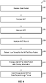
- FIG. 6 is a flow diagram 600 that illustrates an example process to transmit a data packet with NAT, arranged in accordance with at least some embodiments described herein.
- Example processes and methods may include one or more operations, functions or actions as illustrated by one or more of blocks 602, 604, 605, 606, 608, 610, and/or 610, and may in some embodiments be performed by network node such as an edge network device 802 of FIG. 8 .
- the operations described in blocks 602-612 may also be stored as computer-executable instructions in a computer-readable medium such as a memory 814 and/or a data storage 816 of edge network device 802.
- the example process to transmit a data packet with NAT begins with block 602 ("Receive Data Packet"), where a network appliance, such as a customer edge router receives a data packet to process.
- a network appliance such as a customer edge router receives a data packet to process.
- the customer edge router may be located at an edge of a carrier network that is being managed by a carrier, and may be configured to provide NAT functionality.
- the customer edge router may be one of multiple devices that collectively provide a virtualized CGN domain in a network function layer.
- Block 602 is followed by block 604 ("Perform NAT"), where the customer edge router performs NAT on the received data packet.
- the customer edge router translates the source IP address specified in the received data packet to its public IP address (e.g., the public IP address assigned to the customer edge router).
- Block 604 is followed by block 605 ("Maintain VRF"), where the customer edge router maintains a record of the address mapping and/or routing within a particular VPN for the data packet. For example, if the data packet is received from a computing device within a given VPN, the address of the computing device may be entered in the VRF
- Block 605 is followed by block 606 ("Maintain NAT Record"), where the customer edge router maintains a record of the address translation (e.g., mapping) of the private IP address to the public IP address.
- the customer edge router maintains the record of the address translation a NAT table.
- the customer edge router includes the VPN to which the data packet belongs in the record of the address translation.
- Block 606 is followed by block 608 ("Determine a Tunnel for the NAT'ed Data Packet"), where the customer edge router selects an appropriate tunnel to forward the NAT'ed data packet.
- the customer edge router selects an appropriate aggregation router to receive the NAT'ed data packet.
- the appropriate aggregation router may be an aggregation router in an aggregation platform layer that corresponds to the network function layer of the customer edge router.
- the customer edge router has established respective tunnels to the aggregation routers in the corresponding aggregation platform layer.
- Block 608 is followed by block 610 ("Encapsulate NAT'ed Data Packet with Overlay Information"), where the network node encapsulates the NAT'ed data packet with the overlay information corresponding to the selected tunnel.
- the overlay information may include a port address of the customer edge router and a port address of the aggregation router used to establish the selected tunnel.
- Block 610 is followed by block 612 ("Send Encapsulated NAT'ed Data Packet through Tunnel"), where the customer edge router sends the encapsulated NAT'ed data packet through the selected tunnel.
- the aggregation router at the other end of the selected tunnel may remove the overlay information from the encapsulated NAT'ed data packet and forward the de-encapsulated NAT'ed data packet to the specified destination.
- the aggregation router may maintain a record of the route (e.g., tunnel) through which the encapsulated NAT'ed data packet is received.
- the record may include the source IP address specified in the removed overlay information and the source IP address specified in the de-encapsulated NAT'ed data packet.
- FIG. 7 is a flow diagram 700 that illustrates an example process to transmit a return data packet corresponding to a NAT'ed data packet, arranged in accordance with at least some embodiments described herein.
- Example processes and methods may include one or more operations, functions or actions as illustrated by one or more of blocks 702, 704, 706, and/or 708, and may in some embodiments be performed by network node such as an edge network device 802 of FIG. 8 .
- the operations described in blocks 702-708 may also be stored as computer-executable instructions in a computer-readable medium such as a memory 814 and/or a data storage 816 of edge network device 802.
- the example process to transmit a return data packet corresponding to a NAT'ed data packet may begin with block 702 ("Receive Data Packet"), where a network appliance, such as an aggregation router may receive a data packet to process.
- a network appliance such as an aggregation router may receive a data packet to process.
- the aggregation router may be located at or near a public edge of a carrier network, and may be configured to direct network traffic to customer edge routers that may be providing a virtual CGN functionality.
- the aggregation router may be one of a number of devices in an aggregation platform layer.
- the aggregation router may determine from the destination IP address of the received data packet that the data packet is to be forwarded to a customer edge router in a function endpoint layer that corresponds to the aggregation platform layer.
- Block 702 may be followed by block 704 ("Determine a Tunnel for the Data Packet"), where the aggregation router may identify a tunnel through which to forward the data packet to an appropriate customer edge router. For example, the aggregation router may identify the tunnel based on the destination IP address specified in the received data packet and its routing table. The aggregation router may be maintaining a routing table whose entries identify the tunnel through which NAT'ed data packets are received from the function endpoint layer.
- Block 704 may be followed by block 706 ("Encapsulate the Data Packet with Overlay Information"), where the aggregation router may encapsulate the data packet with overlay information that corresponds to the identified tunnel.
- the overlay information may include a port address of the aggregation router and a port address of the customer edge router used to establish the identified tunnel.
- Block 706 may be followed by block 708 ("Send Encapsulated Data Packet through Tunnel"), where the aggregation router may send the encapsulated data packet through the identified tunnel.
- the customer edge router at the other end of the identified tunnel removes the overlay information from the encapsulated data packet.
- the customer edge router determines to perform a reverse NAT on the de-encapsulated data packet. For example, the customer edge router may determine that the destination IP address specified in the de-encapsulated data packet is its device address (e.g., the public device address of the customer edge router), and determine from this to perform a reverse NAT to correctly forward the de-encapsulated data packet to the proper destination.
- the customer edge router identifies the correct destination IP address (e.g., the private IP address) from its NAT table, and reverse NAT the destination IP address specified in the de-encapsulated data packet to create a reverse NAT'ed data packet.
- the customer edge router is maintaining a NAT table whose entries identify the mappings of the translations from a private IP address to its device address (e.g., the public IP address of the customer edge router).
- the customer edge router forwards the reverse NAT'ed data packet on its way to the destination address specified in reverse NAT'ed data packet.
- the customer edge router identifies a VPN associated with the return data packet and performs a lookup in the VRF table for the VPN to determine where the return data packet is to be routed.
- FIG. 8 illustrates an environment 800 of edge network device 802 that may be used to provide a virtualized network function through address space aggregation, arranged in accordance with at least some embodiments described herein.
- edge network device 802 that may include multiple potential connections for communicating with other edge network devices 804, 806, and 808.
- edge network device 802 may communicate with edge network device 804 using a network A 860, with edge network device 806 using a network B 870, and/or with edge network device 808 using a network C 880.
- Edge network devices 802, 804, 806, and 808 may be similar or comparable to aggregation routers 102a and 102b and customer edge routers 104a, 104b, 106a, and 106b of FIGS. 1-5 .
- Environment 800 may additionally include a client device 850 that may be communicatively coupled to edge network device 802, for example, across an external network domain.
- edge network device 802 may include a network A connection 820, a network B connection 830, and a network C connection 840. As illustrated by the ellipses below network C connection 840, any number of additional or other potential connections may also be included. In these and other embodiments, edge network device 802 may include multiple circuits for connecting to the one or more potential connections. For example, edge network device 802 may include a circuit A 822 and a circuit B 824 for network A connection 820, a circuit A 832 and a circuit B 834 for network B connection 830, and a circuit A 842 and a circuit B 844 for network C connection 840. In these and other embodiments, edge network device 802 may be configured to route traffic along one or more of the circuits, based on one or more policies stored by edge network device 802.
- edge network device 802 may be configured to monitor one or more properties of the various connections. For example, edge network device 802 may monitor the jitter, latency, loss, and/or bandwidth of the various communication links from edge network device 802 to edge network device 804, 806, and/or 808. In these and other embodiments, edge network device 802 may also monitor and/or store security properties of the various communication links. For example, links 862 and 864 over network A 860 may be considered at a first level of security, links 872 and 874 over network B 870 may be considered at a second level of security, and links 882 and 884 over network C 880 may be considered at a third level of security. In some embodiments, one or more of links 862, 864, 872, 874, 882, and/or 884 may be tunnels, such as GRE tunnels, IPsec tunnels, L2TP tunnels, and/or others.
- tunnels such as GRE tunnels, IPsec tunnels, L2TP tunnels, and/or others.
- edge network device 802 may be configured to route traffic to the various links based on the source of the traffic. For example, one or more policies may indicate that traffic from one corporate department of a business be routed along network B connection 830, while traffic for another corporate department may be routed along any link.
- edge network device 802 may include a processor 812, a memory 814, a storage device 816, and/or a communication device 818.
- processor 812 may include any suitable special-purpose or general-purpose computer, computing entity, or processing device including various computer hardware or software modules, and may be configured to execute instructions stored on any applicable computer-readable storage media.
- processor 812 may include a microprocessor, a microcontroller, a digital signal processor (DSP), an application-specific integrated circuit (ASIC), a Field-Programmable Gate Array (FPGA), or any other digital or analog circuitry configured to interpret and/or to execute program instructions and/or to process data.
- DSP digital signal processor
- ASIC application-specific integrated circuit
- FPGA Field-Programmable Gate Array
- processor 812 may include any number of processors distributed across any number of network or physical locations that are configured to perform individually or collectively any number of operations described in the present disclosure.
- processor 812 may interpret and/or execute program instructions and/or process data stored in memory 814, storage device 816, or memory 814 and storage device 816.
- processor 812 may fetch program instructions from data storage 816 and load the program instructions into memory 814. After the program instructions are loaded into memory 814, processor 812 may execute the program instructions.
- Memory 814 and storage device 816 may include computer-readable storage media or one or more computer-readable storage mediums for carrying or having computer-executable instructions or data structures stored thereon.
- Such computer-readable storage media may be any available media that may be accessed by a general-purpose or special-purpose computer, such as processor 812.
- edge network device 802 may or may not include either of memory 814 and storage device 816.
- such computer-readable storage media may include non-transitory computer-readable storage media including Random Access Memory (RAM), Read-Only Memory (ROM), Electrically Erasable Programmable Read-Only Memory (EEPROM), Compact Disc Read-Only Memory (CD-ROM) or other optical disk storage, magnetic disk storage or other magnetic storage devices, flash memory devices (e.g., solid state memory devices), or any other storage medium which may be used to carry or store desired program code in the form of computer-executable instructions or data structures and which may be accessed by a general-purpose or special-purpose computer. Combinations of the above may also be included within the scope of computer-readable storage media.
- Computer-executable instructions may include, for example, instructions and data configured to cause processor 812 to perform a certain operation or group of operations.
- Communication device 818 may include any component, device, system, or combination thereof that is configured to transmit or receive information. In some embodiments, communication device 818 may communicate with other devices at other locations, the same location, or even other components within the same system.
- communication device 818 may include a modem, a network card (wireless or wired), an optical communication device, a radio frequency transducer, an ultrasonic transducer, an infrared communication device, a wireless communication device (such as an antenna), and/or chipset (such as a Bluetooth device, an 802.6 device (e.g., Metropolitan Area Network (MAN)), a WiFi device, a WiMax device, cellular communication facilities, or others), and/or the like, and/or combinations thereof.
- MAN Metropolitan Area Network
- Communication device 818 may permit data to be exchanged with a network and/or any other devices or systems described in the present disclosure.
- communication device 818 may allow edge network device 802 to communicate with other systems, such as any one or more of edge network devices 804, 806, and 808.
- environment 800 of FIG. 8 may include any number of edge network devices.
- environment 800 may include three communication networks (network A 860, network B 870, and network C 880) any number of communication networks may be utilized.
- embodiments described in the present disclosure may include the use of a special purpose or general purpose computer (e.g., processor 812 of FIG. 8 ) including various computer hardware or software modules, as discussed in greater detail herein. Further, as indicated above, embodiments described in the present disclosure may be implemented using computer-readable media (e.g., memory 814 of FIG. 8 ) for carrying or having computer-executable instructions or data structures stored thereon.
- a special purpose or general purpose computer e.g., processor 812 of FIG. 8
- computer-readable media e.g., memory 814 of FIG. 8
- module or “component” may refer to specific hardware implementations configured to perform the actions of the module or component and/or software objects or software routines that may be stored on and/or executed by general purpose hardware (e.g., computer-readable media, processing devices, etc.) of the computing system.
- general purpose hardware e.g., computer-readable media, processing devices, etc.
- the different components, modules, engines, and services described in the present disclosure may be implemented as objects or processes that execute on the computing system (e.g., as separate threads). While some of the system and methods described in the present disclosure are generally described as being implemented in software (stored on and/or executed by general purpose hardware), specific hardware implementations, firmware implements, or any combination thereof are also possible and contemplated.
- a "computing entity” may be any computing system as previously described in the present disclosure, or any module or combination of modulates executing on a computing system.
Landscapes
- Engineering & Computer Science (AREA)
- Computer Networks & Wireless Communication (AREA)
- Signal Processing (AREA)
- Data Exchanges In Wide-Area Networks (AREA)
Claims (9)
- Verfahren zum Bereitstellen von Adressübersetzung an einem ersten Kunden-Edge-Router (104a), wobei der erste Kunden-Edge-Router einer aus einer Vielzahl von Kunden-Edge-Routern (104a, 104b, 106a, 106b) ist, wobei das Verfahren Folgendes umfasst:Einrichten, durch den ersten Kunden-Edge-Router (104a), eines Tunnels (112a, 112b) zwischen dem ersten Kunden-Edge-Router (104a) und jedem einer Vielzahl von Aggregationsroutern (102a, 102b);Durchführen, durch den ersten Kunden-Edge-Router (104a), einer Netzwerkadressenübersetzung (Network Address Translation, NAT) an einem ersten Datenpaket, um ein mit NAT versehenes erstes Datenpaket zu erzeugen, wobei die NAT eine Übersetzung einer privaten IP-Adresse in eine öffentliche IP-Adresse ist;Aufrechterhalten einer Aufzeichnung der NAT in einer NAT-Tabelle durch den ersten Kunden-Edge-Router (104a) und Erzeugen eines Eintrags in der NAT-Tabelle, der ein virtuelles privates Netzwerk (VPN) identifiziert, das mit dem ersten Datenpaket verbunden ist;Aufrechterhalten einer virtuellen Routing- und Weiterleitungstabelle (VRF) für das VPN durch den ersten Kunden-Edge-Router (104a);Auswählen, durch den ersten Kunden-Edge-Router (104a), eines ersten Aggregationsrouters (102a) aus der Vielzahl von Aggregationsroutern (102a, 102b), zu dem das mit NAT versehene erste Datenpaket gesendet werden soll;Verkapseln, durch den ersten Kunden-Edge-Router (104a), des mit NAT versehenen ersten Datenpakets mit Überlagerungsinformationen, die einem Tunnel (112a) entsprechen, der zwischen dem ersten Kunden-Edge-Router (104a) und dem ersten Aggregationsrouter (102a) eingerichtet wurde;Senden, durch den ersten Kunden-Edge-Router (104a), des verkapselten mit NAT versehenen ersten Datenpakets durch den Tunnel an den ersten Aggregationsrouter (102a);Empfangen, durch den ersten Kunden-Edge-Router (104a), eines Rückdatenpakets von dem ersten Aggregationsrouter (102a) durch den Tunnel (112a);Entfernen, durch den ersten Kunden-Edge-Router (104a), von Überlagerungsinformationen aus dem Rückdatenpaket, um das Rückdatenpaket zu entkapseln;Durchführen, durch den ersten Kunden-Edge-Router (104a), von Umkehr-NAT an dem Rückdatenpaket, um eine öffentliche IP-Adresse in eine private IP-Adresse basierend auf der NAT-Tabelle zu übersetzen;Identifizieren, durch den ersten Kunden-Edge-Router (104a), eines VPN, das der privaten IP-Adresse des Rückdatenpakets zugeordnet ist, basierend auf der NAT-Tabelle;Identifizieren, durch den ersten Kunden-Edge-Router (104a), einer Schnittstelle des ersten Kunden-Edge-Routers (104a), durch die das Rückdatenpaket geleitet werden soll, basierend auf der VRF-Tabelle für das identifizierte VPN; undLeiten, durch den ersten Kunden-Edge-Router (104a), des Rückdatenpakets über die Schnittstelle, die anhand der VRF-Tabelle identifiziert wurde.
- Verfahren nach Anspruch 1, wobei die öffentliche IP-Adresse eine Vorrichtungsadresse des ersten Kunden-Edge-Routers (104a) ist.
- Verfahren nach Anspruch 2, wobei die Vorrichtungsadresse eine individuelle IP-Adresse in einem funktionalen IP-Adressraum des ersten Aggregationsrouters (102a) ist.
- Verfahren nach einem der Ansprüche 1 bis 3, wobei der erste Kunden-Edge-Router (104a) und der erste Aggregationsrouter (102a) von einem ersten Betreiber bereitgestellt werden, und der Tunnel zwischen dem ersten Kunden-Edge-Router (104a) und dem ersten Aggregationsrouter (102a) unter Verwendung einer von dem ersten Betreiber bereitgestellten Netzwerkschaltung eingerichtet wird.
- Verfahren nach einem der Ansprüche 1 bis 3, wobei der erste Kunden-Edge-Router (104a) und der erste Aggregationsrouter (102a) von einem ersten Betreiber bereitgestellt werden, und der Tunnel zwischen dem ersten Kunden-Edge-Router (104a) und dem ersten Aggregationsrouter (102a) unter Verwendung einer von einem zweiten Betreiber bereitgestellten Netzwerkschaltung eingerichtet wird.
- Verfahren nach einem der Ansprüche 1 bis 5, wobei die Überlagerungsinformationen einen Überlagerungskopfdatensatz umfassen, wobei der Überlagerungskopfdatensatz eine Port-Adresse des ersten Kunden-Edge-Routers (104a) und eine Port-Adresse des ersten Aggregationsrouters (102a) umfasst, die zum Aufbau des Tunnels (112a) zwischen dem ersten Kunden-Edge-Router (104a) und dem ersten Aggregationsrouter (102a) verwendet werden.
- Vorrichtung zum Bereitstellen von Adressübersetzung an einem ersten Kunden-Edge-Router (104a), wobei der erste Kunden-Edge-Router einer aus einer Vielzahl von Kunden-Edge-Routern (104a, 104b, 106a, 106b) ist, wobei die Vorrichtung Folgendes umfasst:ein Mittel zum Einrichten, durch den ersten Kunden-Edge-Router (104a), eines Tunnels (112a, 112b) zwischen dem ersten Kunden-Edge-Router (104a) und jedem einer Vielzahl von Aggregationsroutern (102a, 102b);ein Mittel zum Durchführen, durch den ersten Kunden-Edge-Router (104a), einer Netzwerkadressenübersetzung, NAT, an einem ersten Datenpaket, um ein mit NAT versehenes erstes Datenpaket zu erzeugen, wobei die NAT eine Übersetzung einer privaten IP-Adresse in eine öffentliche IP-Adresse ist;ein Mittel zum Aufrechterhalten einer Aufzeichnung des NAT in einer NAT-Tabelle durch den ersten Kunden-Edge-Router (104a), und ein Mittel zum Erzeugen eines Eintrags in der NAT-Tabelle, der ein virtuelles privates Netzwerk (VPN) identifiziert, das mit dem ersten Datenpaket verbunden ist;ein Mittel zum Aufrechterhalten einer virtuellen Routing- und Weiterleitungstabelle (VRF) für das VPN durch den ersten Kunden-Edge-Router (104a);ein Mittel zum Auswählen, durch den ersten Kunden-Edge-Router (104a), eines ersten Aggregationsrouters (102a) aus der Vielzahl von Aggregationsroutern (102a, 102b), zu dem das mit NAT versehene erste Datenpaket gesendet werden soll;ein Mittel zum Verkapseln, durch den ersten Kunden-Edge-Router (104a), des mit NAT versehenen ersten Datenpakets mit Überlagerungsinformationen, die einem Tunnel (112a) entsprechen, der zwischen dem ersten Kunden-Edge-Router (104a) und dem ersten Aggregationsrouter (102a) eingerichtet wurde;ein Mittel zum Senden, durch den ersten Kunden-Edge-Router (104a), des verkapselten mit NAT versehenen ersten Datenpakets durch den Tunnel an den ersten Aggregationsrouter (102a);ein Mittel zum Empfangen, durch den ersten Kunden-Edge-Router (104a), eines Rückdatenpakets von dem ersten Aggregationsrouter (102a) durch den Tunnel (112a);ein Mittel zum Entfernen, durch den ersten Kunden-Edge-Router (104a), von Überlagerungsinformationen aus dem Rückdatenpaket, um das Rückdatenpaket zu entkapseln;ein Mittel zum Durchführen, durch den ersten Kunden-Edge-Router (104a), von Umkehr-NAT an dem Rückdatenpaket, um eine öffentliche IP-Adresse in eine private IP-Adresse basierend auf der NAT-Tabelle zu übersetzen;ein Mittel zum Identifizieren, durch den ersten Kunden-Edge-Router (104a), eines VPN, das der privaten IP-Adresse des Rückdatenpakets zugeordnet ist, basierend auf der NAT-Tabelle;ein Mittel zum Identifizieren, durch den ersten Kunden-Edge-Router (104a), einer Schnittstelle des ersten Kunden-Edge-Routers (104a), durch die das Rückdatenpaket geleitet werden soll, basierend auf der VRF-Tabelle für das identifizierte VPN; undein Mittel zum Leiten, durch den ersten Kunden-Edge-Router (104a), des Rückdatenpakets über die Schnittstelle, die anhand der VRF-Tabelle identifiziert wurde.
- Vorrichtung nach Anspruch 7, die ferner Mittel zur Durchführung des Verfahrens nach einem der Ansprüche 2 bis 6 umfasst.
- Computerprogramm, Computerprogrammprodukt oder computerlesbares Medium mit Befehlen, die, wenn sie von einem Computer ausgeführt werden, den Computer veranlassen, die Schritte des Verfahrens nach einem der Ansprüche 1 bis 6 auszuführen.
Applications Claiming Priority (2)
| Application Number | Priority Date | Filing Date | Title |
|---|---|---|---|
| US15/664,869 US11522828B2 (en) | 2017-07-31 | 2017-07-31 | Virtualized network functions through address space aggregation |
| PCT/US2018/043618 WO2019027749A1 (en) | 2017-07-31 | 2018-07-25 | VIRTUALIZED NETWORK FUNCTIONS BY ADDRESSABLE SPACE AGGREGATION |
Publications (2)
| Publication Number | Publication Date |
|---|---|
| EP3662647A1 EP3662647A1 (de) | 2020-06-10 |
| EP3662647B1 true EP3662647B1 (de) | 2022-10-19 |
Family
ID=63405339
Family Applications (1)
| Application Number | Title | Priority Date | Filing Date |
|---|---|---|---|
| EP18760072.1A Active EP3662647B1 (de) | 2017-07-31 | 2018-07-25 | Virtualisierte netzwerkfunktionen durch adressraumaggregation |
Country Status (6)
| Country | Link |
|---|---|
| US (2) | US11522828B2 (de) |
| EP (1) | EP3662647B1 (de) |
| JP (1) | JP6967657B2 (de) |
| CN (1) | CN110945855B (de) |
| CA (1) | CA3071801C (de) |
| WO (1) | WO2019027749A1 (de) |
Cited By (1)
| Publication number | Priority date | Publication date | Assignee | Title |
|---|---|---|---|---|
| US12495044B2 (en) | 2023-06-14 | 2025-12-09 | Zscaler, Inc. | Unified identity platform for multiple cloud services |
Families Citing this family (13)
| Publication number | Priority date | Publication date | Assignee | Title |
|---|---|---|---|---|
| US8560634B2 (en) * | 2007-10-17 | 2013-10-15 | Dispersive Networks, Inc. | Apparatus, systems and methods utilizing dispersive networking |
| US11522828B2 (en) * | 2017-07-31 | 2022-12-06 | Cisco Technology, Inc. | Virtualized network functions through address space aggregation |
| CN110417658B (zh) * | 2018-04-28 | 2022-08-12 | 北京京东尚科信息技术有限公司 | 用于边缘路由器的网络接入方法和装置 |
| CN112787932B (zh) * | 2019-11-05 | 2022-09-02 | 华为技术有限公司 | 一种用于生成转发信息的方法、装置和系统 |
| WO2021171365A1 (ja) * | 2020-02-25 | 2021-09-02 | 日本電信電話株式会社 | 経路情報管理装置、経路情報管理方法及びプログラム |
| CN111464446B (zh) * | 2020-04-08 | 2022-04-12 | 广州虎牙科技有限公司 | 多线路服务器访问的通信方法、装置和服务器 |
| CN112367237B (zh) * | 2020-09-29 | 2022-10-21 | 新华三技术有限公司 | 一种报文转发方法及系统 |
| CN112333078B (zh) * | 2021-01-06 | 2021-04-16 | 杭州网银互联科技股份有限公司 | 一种sd-wan数据转发平面的构建方法、系统 |
| US20220311735A1 (en) * | 2021-03-25 | 2022-09-29 | At&T Intellectual Property I, L.P. | Carrier grade network address translation architecture and implementation |
| US11481514B1 (en) * | 2021-09-03 | 2022-10-25 | Beijing Bytedance Network Technology Co., Ltd. | Solution for trustworthy and security compliant edge computing infrastructure |
| US12267235B1 (en) * | 2022-05-23 | 2025-04-01 | Amazon Technologies, Inc. | Switchover across network service providers in a last-mile network |
| CA3257779A1 (en) * | 2022-06-05 | 2023-12-14 | Level 3 Communications, Llc | EFFICIENT PROVISION OF INTERNET CIRCUIT AND SECURE DOMAIN NAME SYSTEM |
| WO2025140331A1 (zh) * | 2023-12-25 | 2025-07-03 | 何岳 | 一种网络边缘的应用服务系统 |
Citations (1)
| Publication number | Priority date | Publication date | Assignee | Title |
|---|---|---|---|---|
| WO2015147943A1 (en) * | 2014-03-27 | 2015-10-01 | Nicira, Inc. | Distributed network address translation for cloud service access |
Family Cites Families (37)
| Publication number | Priority date | Publication date | Assignee | Title |
|---|---|---|---|---|
| US20020038419A1 (en) * | 2000-03-20 | 2002-03-28 | Garrett John W. | Service selection in a shared access network using tunneling |
| US6980526B2 (en) * | 2000-03-24 | 2005-12-27 | Margalla Communications, Inc. | Multiple subscriber videoconferencing system |
| JP2003244251A (ja) * | 2002-02-18 | 2003-08-29 | Telecommunication Advancement Organization Of Japan | トンネル経路を再構成するパケット通信方法 |
| EP1488332A4 (de) * | 2002-03-11 | 2005-12-07 | Seabridge Ltd | Ansammlung von ppp-sitzungen mit dynamischem dienstbewusstsein über variable netzwerktunnel |
| US7715380B2 (en) * | 2003-06-19 | 2010-05-11 | Cisco Technology, Inc. | Apparatus and methods for handling shared services through virtual route forwarding (VRF)-aware-NAT |
| US7916739B2 (en) * | 2003-06-24 | 2011-03-29 | Ntt Docomo, Inc. | Location privacy for internet protocol networks using cryptographically protected prefixes |
| US8036221B2 (en) * | 2004-06-14 | 2011-10-11 | Cisco Technology, Inc. | Method and system for dynamic secured group communication |
| US7411975B1 (en) * | 2004-08-26 | 2008-08-12 | Juniper Networks, Inc. | Multimedia over internet protocol border controller for network-based virtual private networks |
| US20060062206A1 (en) * | 2004-09-23 | 2006-03-23 | Vijayaraghavan Krishnaswamy | Multi-link PPP over heterogeneous single path access networks |
| US8121146B2 (en) | 2005-09-21 | 2012-02-21 | Intel Corporation | Method, apparatus and system for maintaining mobility resistant IP tunnels using a mobile router |
| US7933257B2 (en) * | 2006-09-20 | 2011-04-26 | Cisco Technology, Inc. | Using QoS tunnels for TCP latency optimization |
| US8316435B1 (en) * | 2008-08-14 | 2012-11-20 | Juniper Networks, Inc. | Routing device having integrated MPLS-aware firewall with virtual security system support |
| US8812347B2 (en) * | 2009-05-21 | 2014-08-19 | At&T Mobility Ii Llc | Aggregating and capturing subscriber traffic |
| US8161190B2 (en) * | 2009-12-14 | 2012-04-17 | At&T Intellectual Property I, L.P. | System and method to manage static internet protocol addresses |
| US8705530B2 (en) * | 2010-07-29 | 2014-04-22 | At&T Intellectual Property I, L.P. | Methods and apparatus to implement multipoint and replicated communication paths using upstream and recursive downstream label mappings |
| CN102006337B (zh) * | 2010-11-23 | 2013-12-18 | 华为技术有限公司 | 一种基于cgn实体的数据传输方法、cgn实体、网关及系统 |
| US20120151057A1 (en) * | 2010-12-03 | 2012-06-14 | Level 3 Communications, Llc | Virtualized connectivity in a cloud services environment |
| US8713628B2 (en) * | 2011-02-08 | 2014-04-29 | Verizon Patent And Licensing Inc. | Method and system for providing cloud based network security services |
| JP5601251B2 (ja) * | 2011-03-10 | 2014-10-08 | 富士通株式会社 | 通信方法および通信システム |
| US8725898B1 (en) * | 2011-03-17 | 2014-05-13 | Amazon Technologies, Inc. | Scalable port address translations |
| US9628294B1 (en) * | 2011-03-23 | 2017-04-18 | Amazon Technologies, Inc. | Methods and apparatus for remapping public network addresses on a network to an external network via a private communications channel |
| CN102546407B (zh) | 2011-12-29 | 2018-01-23 | 江苏悦达数梦技术有限公司 | 报文发送方法及装置 |
| US8659992B2 (en) * | 2012-02-14 | 2014-02-25 | Cable Television Laboratories, Inc. | Network address translation |
| US10389608B2 (en) * | 2013-03-15 | 2019-08-20 | Amazon Technologies, Inc. | Network traffic mapping and performance analysis |
| JP5904965B2 (ja) * | 2013-03-25 | 2016-04-20 | 西日本電信電話株式会社 | 通信装置及び通信システム |
| US20150124622A1 (en) * | 2013-11-01 | 2015-05-07 | Movik Networks, Inc. | Multi-Interface, Multi-Layer State-full Load Balancer For RAN-Analytics Deployments In Multi-Chassis, Cloud And Virtual Server Environments |
| US9807057B1 (en) * | 2013-12-17 | 2017-10-31 | Amazon Technologies, Inc. | Private network peering in virtual network environments |
| JP5967173B2 (ja) * | 2014-01-31 | 2016-08-10 | 株式会社バッファロー | ネットワーク中継装置、ネットワーク中継装置が有するパケット中継処理部の動作モードを設定する方法、およびコンピュータープログラム |
| US9641434B1 (en) * | 2014-12-17 | 2017-05-02 | Amazon Technologies, Inc. | Private network address obfuscation and verification |
| US9948552B2 (en) * | 2015-04-17 | 2018-04-17 | Equinix, Inc. | Cloud-based services exchange |
| US9967237B2 (en) * | 2015-09-17 | 2018-05-08 | Cox Communications, Inc. | Systems and methods for implementing a layer two tunnel for personalized service functions |
| US20170118127A1 (en) * | 2015-10-22 | 2017-04-27 | Cox Communications, Inc. | Systems and Methods of Virtualized Services |
| US10037221B2 (en) * | 2015-12-28 | 2018-07-31 | Amazon Technologies, Inc. | Management of virtual desktop instance pools |
| US10498810B2 (en) * | 2017-05-04 | 2019-12-03 | Amazon Technologies, Inc. | Coordinating inter-region operations in provider network environments |
| US10666606B2 (en) * | 2017-06-28 | 2020-05-26 | Amazon Technologies, Inc. | Virtual private network service endpoints |
| US11522828B2 (en) * | 2017-07-31 | 2022-12-06 | Cisco Technology, Inc. | Virtualized network functions through address space aggregation |
| US11863515B2 (en) * | 2021-12-10 | 2024-01-02 | Cisco Technology, Inc. | Systems and methods for translating IPV6 packets for DIA in an SD-WAN environment |
-
2017
- 2017-07-31 US US15/664,869 patent/US11522828B2/en active Active
-
2018
- 2018-07-25 CN CN201880049793.2A patent/CN110945855B/zh active Active
- 2018-07-25 JP JP2020503036A patent/JP6967657B2/ja active Active
- 2018-07-25 EP EP18760072.1A patent/EP3662647B1/de active Active
- 2018-07-25 CA CA3071801A patent/CA3071801C/en active Active
- 2018-07-25 WO PCT/US2018/043618 patent/WO2019027749A1/en not_active Ceased
-
2022
- 2022-11-29 US US18/059,693 patent/US12463936B2/en active Active
Patent Citations (1)
| Publication number | Priority date | Publication date | Assignee | Title |
|---|---|---|---|---|
| WO2015147943A1 (en) * | 2014-03-27 | 2015-10-01 | Nicira, Inc. | Distributed network address translation for cloud service access |
Non-Patent Citations (3)
| Title |
|---|
| BROCKNERS S GUNDAVELLI CISCO S SPEICHER DEUTSCHE TELEKOM AG D WARD JUNIPER NETWORKS F: "Gateway Initiated Dual-Stack Lite Deployment; draft-gundavelli-softwire-gateway-init-ds-lite-03.txt", GATEWAY INITIATED DUAL-STACK LITE DEPLOYMENT; DRAFT-GUNDAVELLI-SOFTWIRE-GATEWAY-INIT-DS-LITE-03.TXT, INTERNET ENGINEERING TASK FORCE, IETF; STANDARDWORKINGDRAFT, INTERNET SOCIETY (ISOC) 4, RUE DES FALAISES CH- 1205 GENEVA, SWITZERLAND, no. 3, 8 March 2010 (2010-03-08), pages 1 - 13, XP015067824 * |
| C EDRIC DE LAUNOIS ET AL: "Connection of Extruded Subnets: A Solution Based on RSIP", IEEE COMMUNICATIONS MAGAZINE, IEEE SERVICE CENTER, PISCATAWAY, US, vol. 40, no. 9, 1 September 2002 (2002-09-01), pages 116 - 121, XP011092919, ISSN: 0163-6804 * |
| JIANG D GUO HUAWEI TECHNOLOGIES CO S ET AL: "An Incremental Carrier-Grade NAT (CGN) for IPv6 Transition; draft-jiang-v6ops-incremental-cgn-01.txt", AN INCREMENTAL CARRIER-GRADE NAT (CGN) FOR IPV6 TRANSITION; DRAFT-JIANG-V6OPS-INCREMENTAL-CGN-01.TXT, INTERNET ENGINEERING TASK FORCE, IETF; STANDARDWORKINGDRAFT, INTERNET SOCIETY (ISOC) 4, RUE DES FALAISES CH- 1205 GENEVA, SWITZERLAND, no. 1, 29 June 2009 (2009-06-29), XP015062885 * |
Cited By (1)
| Publication number | Priority date | Publication date | Assignee | Title |
|---|---|---|---|---|
| US12495044B2 (en) | 2023-06-14 | 2025-12-09 | Zscaler, Inc. | Unified identity platform for multiple cloud services |
Also Published As
| Publication number | Publication date |
|---|---|
| JP2020529762A (ja) | 2020-10-08 |
| EP3662647A1 (de) | 2020-06-10 |
| CA3071801C (en) | 2024-05-14 |
| JP6967657B2 (ja) | 2021-11-17 |
| US11522828B2 (en) | 2022-12-06 |
| WO2019027749A1 (en) | 2019-02-07 |
| US12463936B2 (en) | 2025-11-04 |
| CN110945855B (zh) | 2023-01-31 |
| US20230090829A1 (en) | 2023-03-23 |
| CN110945855A (zh) | 2020-03-31 |
| CA3071801A1 (en) | 2019-02-07 |
| US20190036876A1 (en) | 2019-01-31 |
Similar Documents
| Publication | Publication Date | Title |
|---|---|---|
| EP3662647B1 (de) | Virtualisierte netzwerkfunktionen durch adressraumaggregation | |
| US9749231B2 (en) | Method and system for overlay routing with VXLAN on bare metal servers | |
| EP2856706B1 (de) | Lenkung vlan-markierter datenpakete an entfernte adressen virtueller weiterleitungsinstanzen mithilfe getrennter verwaltungen | |
| US9397940B2 (en) | System and method for providing a translation mechanism in a network environment | |
| US8819267B2 (en) | Network virtualization without gateway function | |
| EP3020164B1 (de) | Träger für erweiterbare segmente virtueller lokaler netzwerke an mehreren datenzentrums-standorten | |
| US20130163594A1 (en) | Overlay-Based Packet Steering | |
| CN108206860A (zh) | 用于管理网络装置上的服务链的方法、相应的网络装置 | |
| EP2548346B1 (de) | Paketknoten zur anwendung von dienstpfad-routing auf der mac-schicht | |
| US10715431B2 (en) | Methods and apparatuses for routing data packets in a network topology | |
| US20250379815A1 (en) | Service identification in ipv6 encapsulations | |
| US20250106170A1 (en) | Automated ordering of service in service chain for software-defined wide area networks | |
| US20260089096A1 (en) | Service Function Proxy for Service Chaining in SRv6 Networks | |
| WO2025155509A1 (en) | Improved scaling efficiency for internal transport services in distributed network elements | |
| Yang et al. | Openflow-based IPv6 rapid deployment mechanism |
Legal Events
| Date | Code | Title | Description |
|---|---|---|---|
| STAA | Information on the status of an ep patent application or granted ep patent |
Free format text: STATUS: UNKNOWN |
|
| STAA | Information on the status of an ep patent application or granted ep patent |
Free format text: STATUS: THE INTERNATIONAL PUBLICATION HAS BEEN MADE |
|
| PUAI | Public reference made under article 153(3) epc to a published international application that has entered the european phase |
Free format text: ORIGINAL CODE: 0009012 |
|
| STAA | Information on the status of an ep patent application or granted ep patent |
Free format text: STATUS: REQUEST FOR EXAMINATION WAS MADE |
|
| 17P | Request for examination filed |
Effective date: 20200127 |
|
| AK | Designated contracting states |
Kind code of ref document: A1 Designated state(s): AL AT BE BG CH CY CZ DE DK EE ES FI FR GB GR HR HU IE IS IT LI LT LU LV MC MK MT NL NO PL PT RO RS SE SI SK SM TR |
|
| AX | Request for extension of the european patent |
Extension state: BA ME |
|
| DAV | Request for validation of the european patent (deleted) | ||
| DAX | Request for extension of the european patent (deleted) | ||
| STAA | Information on the status of an ep patent application or granted ep patent |
Free format text: STATUS: EXAMINATION IS IN PROGRESS |
|
| 17Q | First examination report despatched |
Effective date: 20201216 |
|
| REG | Reference to a national code |
Ref country code: DE Ref legal event code: R079 Ref document number: 602018042003 Country of ref document: DE Free format text: PREVIOUS MAIN CLASS: H04L0029120000 Ipc: H04L0061259200 |
|
| RIC1 | Information provided on ipc code assigned before grant |
Ipc: H04L 61/2592 20220101AFI20220426BHEP |
|
| INTG | Intention to grant announced |
Effective date: 20220517 |
|
| GRAS | Grant fee paid |
Free format text: ORIGINAL CODE: EPIDOSNIGR3 |
|
| STAA | Information on the status of an ep patent application or granted ep patent |
Free format text: STATUS: GRANT OF PATENT IS INTENDED |
|
| GRAA | (expected) grant |
Free format text: ORIGINAL CODE: 0009210 |
|
| STAA | Information on the status of an ep patent application or granted ep patent |
Free format text: STATUS: THE PATENT HAS BEEN GRANTED |
|
| AK | Designated contracting states |
Kind code of ref document: B1 Designated state(s): AL AT BE BG CH CY CZ DE DK EE ES FI FR GB GR HR HU IE IS IT LI LT LU LV MC MK MT NL NO PL PT RO RS SE SI SK SM TR |
|
| REG | Reference to a national code |
Ref country code: GB Ref legal event code: FG4D |
|
| REG | Reference to a national code |
Ref country code: CH Ref legal event code: EP |
|
| REG | Reference to a national code |
Ref country code: DE Ref legal event code: R096 Ref document number: 602018042003 Country of ref document: DE |
|
| REG | Reference to a national code |
Ref country code: IE Ref legal event code: FG4D |
|
| REG | Reference to a national code |
Ref country code: AT Ref legal event code: REF Ref document number: 1526271 Country of ref document: AT Kind code of ref document: T Effective date: 20221115 |
|
| REG | Reference to a national code |
Ref country code: LT Ref legal event code: MG9D |
|
| REG | Reference to a national code |
Ref country code: NL Ref legal event code: MP Effective date: 20221019 |
|
| REG | Reference to a national code |
Ref country code: AT Ref legal event code: MK05 Ref document number: 1526271 Country of ref document: AT Kind code of ref document: T Effective date: 20221019 |
|
| PG25 | Lapsed in a contracting state [announced via postgrant information from national office to epo] |
Ref country code: NL Free format text: LAPSE BECAUSE OF FAILURE TO SUBMIT A TRANSLATION OF THE DESCRIPTION OR TO PAY THE FEE WITHIN THE PRESCRIBED TIME-LIMIT Effective date: 20221019 |
|
| PG25 | Lapsed in a contracting state [announced via postgrant information from national office to epo] |
Ref country code: SE Free format text: LAPSE BECAUSE OF FAILURE TO SUBMIT A TRANSLATION OF THE DESCRIPTION OR TO PAY THE FEE WITHIN THE PRESCRIBED TIME-LIMIT Effective date: 20221019 Ref country code: PT Free format text: LAPSE BECAUSE OF FAILURE TO SUBMIT A TRANSLATION OF THE DESCRIPTION OR TO PAY THE FEE WITHIN THE PRESCRIBED TIME-LIMIT Effective date: 20230220 Ref country code: NO Free format text: LAPSE BECAUSE OF FAILURE TO SUBMIT A TRANSLATION OF THE DESCRIPTION OR TO PAY THE FEE WITHIN THE PRESCRIBED TIME-LIMIT Effective date: 20230119 Ref country code: LT Free format text: LAPSE BECAUSE OF FAILURE TO SUBMIT A TRANSLATION OF THE DESCRIPTION OR TO PAY THE FEE WITHIN THE PRESCRIBED TIME-LIMIT Effective date: 20221019 Ref country code: FI Free format text: LAPSE BECAUSE OF FAILURE TO SUBMIT A TRANSLATION OF THE DESCRIPTION OR TO PAY THE FEE WITHIN THE PRESCRIBED TIME-LIMIT Effective date: 20221019 Ref country code: ES Free format text: LAPSE BECAUSE OF FAILURE TO SUBMIT A TRANSLATION OF THE DESCRIPTION OR TO PAY THE FEE WITHIN THE PRESCRIBED TIME-LIMIT Effective date: 20221019 Ref country code: AT Free format text: LAPSE BECAUSE OF FAILURE TO SUBMIT A TRANSLATION OF THE DESCRIPTION OR TO PAY THE FEE WITHIN THE PRESCRIBED TIME-LIMIT Effective date: 20221019 |
|
| PG25 | Lapsed in a contracting state [announced via postgrant information from national office to epo] |
Ref country code: RS Free format text: LAPSE BECAUSE OF FAILURE TO SUBMIT A TRANSLATION OF THE DESCRIPTION OR TO PAY THE FEE WITHIN THE PRESCRIBED TIME-LIMIT Effective date: 20221019 Ref country code: PL Free format text: LAPSE BECAUSE OF FAILURE TO SUBMIT A TRANSLATION OF THE DESCRIPTION OR TO PAY THE FEE WITHIN THE PRESCRIBED TIME-LIMIT Effective date: 20221019 Ref country code: LV Free format text: LAPSE BECAUSE OF FAILURE TO SUBMIT A TRANSLATION OF THE DESCRIPTION OR TO PAY THE FEE WITHIN THE PRESCRIBED TIME-LIMIT Effective date: 20221019 Ref country code: IS Free format text: LAPSE BECAUSE OF FAILURE TO SUBMIT A TRANSLATION OF THE DESCRIPTION OR TO PAY THE FEE WITHIN THE PRESCRIBED TIME-LIMIT Effective date: 20230219 Ref country code: HR Free format text: LAPSE BECAUSE OF FAILURE TO SUBMIT A TRANSLATION OF THE DESCRIPTION OR TO PAY THE FEE WITHIN THE PRESCRIBED TIME-LIMIT Effective date: 20221019 Ref country code: GR Free format text: LAPSE BECAUSE OF FAILURE TO SUBMIT A TRANSLATION OF THE DESCRIPTION OR TO PAY THE FEE WITHIN THE PRESCRIBED TIME-LIMIT Effective date: 20230120 |
|
| P01 | Opt-out of the competence of the unified patent court (upc) registered |
Effective date: 20230525 |
|
| REG | Reference to a national code |
Ref country code: DE Ref legal event code: R097 Ref document number: 602018042003 Country of ref document: DE |
|
| PG25 | Lapsed in a contracting state [announced via postgrant information from national office to epo] |
Ref country code: SM Free format text: LAPSE BECAUSE OF FAILURE TO SUBMIT A TRANSLATION OF THE DESCRIPTION OR TO PAY THE FEE WITHIN THE PRESCRIBED TIME-LIMIT Effective date: 20221019 Ref country code: RO Free format text: LAPSE BECAUSE OF FAILURE TO SUBMIT A TRANSLATION OF THE DESCRIPTION OR TO PAY THE FEE WITHIN THE PRESCRIBED TIME-LIMIT Effective date: 20221019 Ref country code: EE Free format text: LAPSE BECAUSE OF FAILURE TO SUBMIT A TRANSLATION OF THE DESCRIPTION OR TO PAY THE FEE WITHIN THE PRESCRIBED TIME-LIMIT Effective date: 20221019 Ref country code: DK Free format text: LAPSE BECAUSE OF FAILURE TO SUBMIT A TRANSLATION OF THE DESCRIPTION OR TO PAY THE FEE WITHIN THE PRESCRIBED TIME-LIMIT Effective date: 20221019 Ref country code: CZ Free format text: LAPSE BECAUSE OF FAILURE TO SUBMIT A TRANSLATION OF THE DESCRIPTION OR TO PAY THE FEE WITHIN THE PRESCRIBED TIME-LIMIT Effective date: 20221019 |
|
| PLBE | No opposition filed within time limit |
Free format text: ORIGINAL CODE: 0009261 |
|
| STAA | Information on the status of an ep patent application or granted ep patent |
Free format text: STATUS: NO OPPOSITION FILED WITHIN TIME LIMIT |
|
| PG25 | Lapsed in a contracting state [announced via postgrant information from national office to epo] |
Ref country code: SK Free format text: LAPSE BECAUSE OF FAILURE TO SUBMIT A TRANSLATION OF THE DESCRIPTION OR TO PAY THE FEE WITHIN THE PRESCRIBED TIME-LIMIT Effective date: 20221019 Ref country code: AL Free format text: LAPSE BECAUSE OF FAILURE TO SUBMIT A TRANSLATION OF THE DESCRIPTION OR TO PAY THE FEE WITHIN THE PRESCRIBED TIME-LIMIT Effective date: 20221019 |
|
| 26N | No opposition filed |
Effective date: 20230720 |
|
| PG25 | Lapsed in a contracting state [announced via postgrant information from national office to epo] |
Ref country code: SI Free format text: LAPSE BECAUSE OF FAILURE TO SUBMIT A TRANSLATION OF THE DESCRIPTION OR TO PAY THE FEE WITHIN THE PRESCRIBED TIME-LIMIT Effective date: 20221019 |
|
| PG25 | Lapsed in a contracting state [announced via postgrant information from national office to epo] |
Ref country code: MC Free format text: LAPSE BECAUSE OF FAILURE TO SUBMIT A TRANSLATION OF THE DESCRIPTION OR TO PAY THE FEE WITHIN THE PRESCRIBED TIME-LIMIT Effective date: 20221019 |
|
| PG25 | Lapsed in a contracting state [announced via postgrant information from national office to epo] |
Ref country code: MC Free format text: LAPSE BECAUSE OF FAILURE TO SUBMIT A TRANSLATION OF THE DESCRIPTION OR TO PAY THE FEE WITHIN THE PRESCRIBED TIME-LIMIT Effective date: 20221019 |
|
| REG | Reference to a national code |
Ref country code: CH Ref legal event code: PL |
|
| REG | Reference to a national code |
Ref country code: BE Ref legal event code: MM Effective date: 20230731 |
|
| PG25 | Lapsed in a contracting state [announced via postgrant information from national office to epo] |
Ref country code: LU Free format text: LAPSE BECAUSE OF NON-PAYMENT OF DUE FEES Effective date: 20230725 |
|
| PG25 | Lapsed in a contracting state [announced via postgrant information from national office to epo] |
Ref country code: LU Free format text: LAPSE BECAUSE OF NON-PAYMENT OF DUE FEES Effective date: 20230725 |
|
| REG | Reference to a national code |
Ref country code: IE Ref legal event code: MM4A |
|
| PG25 | Lapsed in a contracting state [announced via postgrant information from national office to epo] |
Ref country code: CH Free format text: LAPSE BECAUSE OF NON-PAYMENT OF DUE FEES Effective date: 20230731 |
|
| PG25 | Lapsed in a contracting state [announced via postgrant information from national office to epo] |
Ref country code: IT Free format text: LAPSE BECAUSE OF FAILURE TO SUBMIT A TRANSLATION OF THE DESCRIPTION OR TO PAY THE FEE WITHIN THE PRESCRIBED TIME-LIMIT Effective date: 20221019 Ref country code: BE Free format text: LAPSE BECAUSE OF NON-PAYMENT OF DUE FEES Effective date: 20230731 |
|
| PG25 | Lapsed in a contracting state [announced via postgrant information from national office to epo] |
Ref country code: IE Free format text: LAPSE BECAUSE OF NON-PAYMENT OF DUE FEES Effective date: 20230725 |
|
| PG25 | Lapsed in a contracting state [announced via postgrant information from national office to epo] |
Ref country code: IE Free format text: LAPSE BECAUSE OF NON-PAYMENT OF DUE FEES Effective date: 20230725 |
|
| PG25 | Lapsed in a contracting state [announced via postgrant information from national office to epo] |
Ref country code: BG Free format text: LAPSE BECAUSE OF FAILURE TO SUBMIT A TRANSLATION OF THE DESCRIPTION OR TO PAY THE FEE WITHIN THE PRESCRIBED TIME-LIMIT Effective date: 20221019 |
|
| PG25 | Lapsed in a contracting state [announced via postgrant information from national office to epo] |
Ref country code: BG Free format text: LAPSE BECAUSE OF FAILURE TO SUBMIT A TRANSLATION OF THE DESCRIPTION OR TO PAY THE FEE WITHIN THE PRESCRIBED TIME-LIMIT Effective date: 20221019 |
|
| PG25 | Lapsed in a contracting state [announced via postgrant information from national office to epo] |
Ref country code: CY Free format text: LAPSE BECAUSE OF FAILURE TO SUBMIT A TRANSLATION OF THE DESCRIPTION OR TO PAY THE FEE WITHIN THE PRESCRIBED TIME-LIMIT; INVALID AB INITIO Effective date: 20180725 |
|
| PG25 | Lapsed in a contracting state [announced via postgrant information from national office to epo] |
Ref country code: HU Free format text: LAPSE BECAUSE OF FAILURE TO SUBMIT A TRANSLATION OF THE DESCRIPTION OR TO PAY THE FEE WITHIN THE PRESCRIBED TIME-LIMIT; INVALID AB INITIO Effective date: 20180725 |
|
| PGFP | Annual fee paid to national office [announced via postgrant information from national office to epo] |
Ref country code: DE Payment date: 20250618 Year of fee payment: 8 |
|
| PGFP | Annual fee paid to national office [announced via postgrant information from national office to epo] |
Ref country code: GB Payment date: 20250710 Year of fee payment: 8 |
|
| PGFP | Annual fee paid to national office [announced via postgrant information from national office to epo] |
Ref country code: FR Payment date: 20250716 Year of fee payment: 8 |
|
| PG25 | Lapsed in a contracting state [announced via postgrant information from national office to epo] |
Ref country code: TR Free format text: LAPSE BECAUSE OF FAILURE TO SUBMIT A TRANSLATION OF THE DESCRIPTION OR TO PAY THE FEE WITHIN THE PRESCRIBED TIME-LIMIT Effective date: 20221019 |