EP3662647B1 - Virtualized network functions through address space aggregation - Google Patents
Virtualized network functions through address space aggregation Download PDFInfo
- Publication number
- EP3662647B1 EP3662647B1 EP18760072.1A EP18760072A EP3662647B1 EP 3662647 B1 EP3662647 B1 EP 3662647B1 EP 18760072 A EP18760072 A EP 18760072A EP 3662647 B1 EP3662647 B1 EP 3662647B1
- Authority
- EP
- European Patent Office
- Prior art keywords
- customer edge
- edge router
- data packet
- router
- address
- Prior art date
- Legal status (The legal status is an assumption and is not a legal conclusion. Google has not performed a legal analysis and makes no representation as to the accuracy of the status listed.)
- Active
Links
- 230000002776 aggregation Effects 0.000 title claims description 143
- 238000004220 aggregation Methods 0.000 title claims description 143
- 230000006870 function Effects 0.000 title description 66
- 238000000034 method Methods 0.000 claims description 31
- 238000013519 translation Methods 0.000 claims description 17
- 238000004590 computer program Methods 0.000 claims description 3
- 238000004891 communication Methods 0.000 description 16
- 230000008569 process Effects 0.000 description 15
- 230000014616 translation Effects 0.000 description 11
- 238000010586 diagram Methods 0.000 description 10
- 238000013507 mapping Methods 0.000 description 8
- 230000009471 action Effects 0.000 description 6
- 230000008901 benefit Effects 0.000 description 4
- 238000013500 data storage Methods 0.000 description 3
- 238000012545 processing Methods 0.000 description 3
- 238000007792 addition Methods 0.000 description 2
- 238000010276 construction Methods 0.000 description 2
- 238000007726 management method Methods 0.000 description 2
- 238000012986 modification Methods 0.000 description 2
- 230000004048 modification Effects 0.000 description 2
- 230000003287 optical effect Effects 0.000 description 2
- 230000002730 additional effect Effects 0.000 description 1
- 238000013459 approach Methods 0.000 description 1
- 230000005540 biological transmission Effects 0.000 description 1
- 239000000969 carrier Substances 0.000 description 1
- 230000010267 cellular communication Effects 0.000 description 1
- 230000001419 dependent effect Effects 0.000 description 1
- 238000005538 encapsulation Methods 0.000 description 1
- 238000005516 engineering process Methods 0.000 description 1
- 238000001914 filtration Methods 0.000 description 1
- 238000007689 inspection Methods 0.000 description 1
- 230000007246 mechanism Effects 0.000 description 1
- 239000003607 modifier Substances 0.000 description 1
- 230000006855 networking Effects 0.000 description 1
- 230000008520 organization Effects 0.000 description 1
- 230000004044 response Effects 0.000 description 1
- 239000007787 solid Substances 0.000 description 1
- 230000005641 tunneling Effects 0.000 description 1
Images


Classifications
-
- H—ELECTRICITY
- H04—ELECTRIC COMMUNICATION TECHNIQUE
- H04L—TRANSMISSION OF DIGITAL INFORMATION, e.g. TELEGRAPHIC COMMUNICATION
- H04L61/00—Network arrangements, protocols or services for addressing or naming
- H04L61/09—Mapping addresses
- H04L61/25—Mapping addresses of the same type
- H04L61/2503—Translation of Internet protocol [IP] addresses
- H04L61/2592—Translation of Internet protocol [IP] addresses using tunnelling or encapsulation
-
- H—ELECTRICITY
- H04—ELECTRIC COMMUNICATION TECHNIQUE
- H04L—TRANSMISSION OF DIGITAL INFORMATION, e.g. TELEGRAPHIC COMMUNICATION
- H04L45/00—Routing or path finding of packets in data switching networks
- H04L45/74—Address processing for routing
-
- H—ELECTRICITY
- H04—ELECTRIC COMMUNICATION TECHNIQUE
- H04L—TRANSMISSION OF DIGITAL INFORMATION, e.g. TELEGRAPHIC COMMUNICATION
- H04L61/00—Network arrangements, protocols or services for addressing or naming
- H04L61/09—Mapping addresses
- H04L61/25—Mapping addresses of the same type
- H04L61/2503—Translation of Internet protocol [IP] addresses
- H04L61/2514—Translation of Internet protocol [IP] addresses between local and global IP addresses
Definitions
- the present disclosure relates generally to network communications.
- CGN Carrier-grade Network Address Translation
- This disclosure is generally drawn, inter alia, to methods, apparatus, systems, devices, and/or computer program products related to allowing multiple, distributed network nodes to participate in and enable one or more managed services (interchangeably referred to herein as "network functions" or “functions”) that would typically be delivered using a small number of centralized, large scale network appliances.
- a network service provider (interchangeably referred to herein as a "network carrier” or “carrier”) may employ an aggregation layer that includes a small number of centralized network nodes or aggregation nodes.
- the network service provider may place an enterprise customer on one side of the aggregation layer, and the network infrastructure that is outside of the enterprise customer, such as the Internet, on the other side of the aggregation layer.
- the network service provider may direct all network traffic between the enterprise customer and the network infrastructure outside the enterprise customer through the aggregation layer. That is, all network traffic into and out of the carrier network travels through the small number of centralized aggregation nodes in the aggregation layer.
- a carrier may employ a small number of centralized peering routers or provider edge routers (interchangeably referred to herein as "aggregation nodes” or “aggregation routers”) in the aggregation layer, and place the small number of centralized aggregation routers at or near the public edge of the carrier network.
- the carrier may also employ and manage multiple routers (e.g., customer edge routers) at the edge of the carrier network where the enterprise customer connects to the carrier network.
- the customer edge routers may be located at the various location or premises of the enterprise customer.
- the customer edge routers may connect to the provider edge of the carrier, for example, the aggregation routers, and may be the last points of the carrier.
- the carrier may advertise a public address using the aggregation routers, thus directing the network traffic to the carrier network through the aggregation routers.
- the carrier may provide the appropriate routing between the aggregation routers and the customer edge routers. As all network traffic into and out of the carrier network passes through the small number of centralized aggregation routers, the carrier may provide the managed services at the small number of centralized aggregation routers.
- the carrier is also able to control the route of the return network traffic (e.g., get more network traffic to pass through the carrier network).
- the carrier may provide Carrier-grade Network Address Translation (CGN) at the aggregation routers to direct and control the network traffic into and out of the carrier network through the aggregation routers.
- CGN is an approach where the carrier is able to provide the customer edge routers (e.g., the enterprise customer) private addresses, bring the network traffic from the customer edge routers to the small number of aggregation routers, and translate the private network address to public addresses of the aggregation routers (e.g., the public address advertised by the aggregation routers) at the aggregation routers.
- CGN Carrier-grade Network Address Translation
- the aggregation routers may perform a "reverse" translation for the return network traffic to the customer edge routers. This may require the small number of aggregation routers to maintain a very large, and maybe significant amount of state information as the aggregation routers may be providing CGN for a very large number of network addresses (e.g., network nodes). This may present scalability issues. In addition, a failure of an aggregation router may have a significant impact (e.g., affect a very large number of network nodes) as the aggregation router may be serving hundreds or thousands of customers.
- the present disclosure generally describes any number of distributed network nodes participating in and enabling one or more network functions that would typically be delivered using a small number of centralized aggregation nodes.
- multiple customer edge routers may use a combination of distributed processing and address space aggregation across a carrier network domain where a network function is to be provided to deliver the network function in a virtualized manner.
- CGN function will be described as an example of a virtualized network function.
- network functions such as firewalls, content inspection and filtering, customer premises equipment (CPE), and the like, may be similarly provided in a virtualized manner as described herein with respect to CGN.
- Another example of such a network function may include virtual private networking (VPN) and associated address mapping when transporting packets from and/or to one or more VPNs.
- VPN virtual private networking
- a virtualized CGN function may be provided on an architecture that includes an aggregation platform layer, a function endpoint layer, and an aggregated or functional Internet Protocol (IP) address space.
- the aggregation platform layer may include one or more aggregation routers.
- the aggregation platform layer may terminate the tunnels from the function endpoint layer to act as a gateway between an outside network (e.g., the Internet) and the devices performing the virtualized CGN function.
- the aggregation platform layer may also advertise an aggregated IP address space.
- the advertised aggregated IP address space may provide return routability to the function endpoint layer such that the function endpoint layer appears to be on a carrier network that is providing the virtualized CGN function.
- the function endpoint layer may include the devices that perform the Network Address Translation (NAT) to collectively form a virtualized CGN carrier network (e.g., virtualized CGN domain).
- the virtualized CGN carrier network may be accessible through the aggregation platform layer.
- the function endpoint layer may include one or more customer edge routers. Each customer edge router may establish a tunnel to each aggregation router in the aggregation platform layer to establish an overlay network.
- the aggregated IP address space may be assigned to the customer edge routers in the function endpoint layer as individual IP addresses, for example, on the connections facing the carrier network. In instances where a customer edge router resides in multiple carrier networks, the aggregated IP address space may be assigned to the customer edge router as a logical loopback address.
- the aggregated IP address space may be assigned by the carrier, and advertised from the aggregation routers in the aggregation platform layer.
- the agrregated IP address space may be carrier independent.
- the customer edge routers in the function endpoint may reside in any carrier domain (e.g., carrier network), and be logically tied to the carrier that is providing (managing) the virtualized CGN function.
- each aggregation router may advertise an aggregated IP address space.
- the aggregated IP address space includes the IP addresses assigned to the customer edge routers.
- Each customer edge router performs the NAT using its assigned IP address.
- Each customer edge router establishes a tunnel with each aggregation router. Suitable protocols for establishing a tunnel include, by way of example, Generic Routing Encapsulation (GRE), Internet Protocol Security (IPsec), Layer 2 Tunneling Protocol (L2TP), and/or others.
- GRE Generic Routing Encapsulation
- IPsec Internet Protocol Security
- L2TP Layer 2 Tunneling Protocol
- the customer edge router Upon receiving a data packet (e.g., network traffic) that is subject to NAT (e.g., network traffic from the enterprise customer), the customer edge router performs the NAT of the data packet (e.g. using the IP address assigned to the customer edge router), encapsulates the NAT'ed data packet with overlay information of a tunnel to a specific aggregation router, and sends the encapsulated data packet to the specific aggregation router through the tunnel.
- the specific aggregation router may remove the overlay information, maintain a record of the tunnel through which the data packet is received, and forward the de-encapsulated data packet to the specified destination. For example, the specific aggregation router may maintain the record of the tunnel through which the data packet was received in a routing table.
- the customer edge router performs VPN mapping.
- the customer edge router When receiving a data packet from a VPN, when performing the NAT of the data packet, the customer edge router identifies the VPN with which the data packet is associated. Additionally, the customer edge router maintains a Virtual Routing & Forwarding (VRF) table that identifies which addresses are to be routed within the particular VPN. For example, the customer edge router may store a route target for the route distinguishers to identify the VPN.
- the NAT performed on the data packet may address VPN routing such that the specific aggregation router does not store any VPN information.
- Embodiments of the present disclosure may provide an arrangement such that an enterprise may acquire a data link to a provider (e.g., Verizon or Comcast) and may obtain VPN services via the customer edge routers rather than the provider edge router.
- a provider e.g., Verizon or Comcast
- the aggregation router may forward the return data packet to a specific (e.g., correct) customer edge router based on the addressing information in the return data packet.
- the destination address specified in the return data packet may be that of an address in the aggregated IP address space.
- the source and destination addresses in the return data packet may be the "reverse" of the source and destination addresses in the original, NAT'ed data packet. That is, the original, NAT'ed source address is now the destination address in the return data packet, and the original destination address is now the source address in the return data packet.
- the aggregation router may identify a specific customer edge router, and the tunnel established with the specific customer edge router, based on the previously maintained record of the tunnels through which it received the NAT'ed data packets.
- the aggregation router may encapsulate the return data packet with overlay information of the tunnel to the identified customer edge router, and send the encapsulated return data packet to the identified customer edge router through the tunnel.
- the specific customer edge router removes the overlay information, performs a reverse translation (e.g., reverse NAT) of the return data packet, and forwards the de-encapsulated, reverse translated return data packet to the specified destination.
- a reverse translation e.g., reverse NAT
- the customer edge router When the customer edge router receives the return data packet to perform the reverse NAT, the customer edge router additionally performs VPN mapping.
- the NAT table identifies to which VPN the return data packet is directed to.
- the VRF table of that VPN identifies where the return data packet is to be routed within the VPN.
- the architecture provides for construction of a virtual CGN function by allowing each customer edge router to perform the NAT of the network traffic, using the aggregation routers as entry and exit points to the NAT function, and routing the network traffic in an overlay network using tunnels between each customer edge router and the aggregation routers.
- One benefit provided by the architecture is that any scaling issue is greatly minimized. For example, as the scale of the virtual CGN may be limited by the amount of network traffic and/or the number of tunnels that may be supported by any one aggregation router, this scale issue may be readily addressed by clustering customer edge routers around additional aggregation routers.
- each customer edge router maintains the state information for the network traffic NAT performed by the customer edge router.
- the aggregation routers do not maintain any NAT state information.
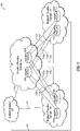
- FIG. 1 illustrates an overview of an environment 100 and devices on which an architecture of the present disclosure may operate, arranged in accordance with at least some embodiments described herein.
- Environment 100 may include a function provider domain 102, network provider domains 104 and 106, and an outside network 108.
- Function provider domain 102, network provider domain 104, and network provider domain 106 may be a carrier network provided and managed by a carrier such as Verizon, AT&T, Sprint, Comcast, and the like.
- Outside network 108 may include any network infrastructure, such as the Internet, one or more connected public networks, and the like, that is external to an enterprise customer.
- Function provider domain 102, network provider domains 104 and 106, and outside network 108 may each be logically connected to the other by communication links 110a-110e.
- Communication links 110a-110e may be interprovider (e.g., intercarrier) links.
- Function provider domain 102 may provide the aggregation platform layer functionality.
- Function provider domain 102 may include a small number of network appliances, such as aggregation routers 102a and 102b. Aggregation routers 102a and 102b may be located or placed at or near the public edge of the carrier network (e.g., function provider domain 102).
- Function provider domain 102 may operate or function as a gateway between network provider domains 104 and 106 and outside network 108.
- Network provider domains 104 and 106 may provide the Network Address Translation (NAT) functionality.
- Network provider domains 104 and 106 may each include multiple network appliances, such as customer edge routers, located or placed at the edge of the carrier network (e.g., network provider domain 104 and network provider domain 106, respectively) where an enterprise customer connects to the carrier network.
- network provider domain 104 may include customer edge routers 104a and 104b located or placed at the enterprise customer edge of the carrier network (e.g., network provider domain 104).
- Network provider domain 106 may include customer edge routers 106a and 106b located or placed at the enterprise customer edge of the carrier network (e.g., network provider domain 106).
- the network provider domain 104 may establish an overlay network with the function provider domain 102.
- each customer edge router 104a, 104b, 106a, and 106b may be configured to establish a tunnel to each aggregation router 102a and 102b in the function provider domain.
- the established tunnels tie or connect the NAT execution locations (e.g., the function execution customer edge routers 104a, 104b, 106a, and 106b) with the aggregation points (e.g., aggregation routers 102a and 102b) to provide a logical reference and connection in an overlay fashion.
- a tunnel 112a may be established between customer edge router 104a and aggregation router 102a
- a tunnel 112b may be established between customer edge router 104a and aggregation router 102b
- a tunnel 112c may be established between customer edge router 104b and aggregation router 102a
- a tunnel 112d may be established between customer edge router 104d and aggregation router 102b
- a tunnel 112e may be established between customer edge router 106a and aggregation router 102a
- a tunnel 112f may be established between customer edge router 106a and aggregation router 102b
- a tunnel 112g may be established between customer edge router 106b and aggregation router 102a
- a tunnel 112h may be established between customer edge router 106d and aggregation router 102b.
- an abstraction mechanism other than tunnels may be used to provide the logical reference and connection between the network provider domain 104 and the function provider domain 102.
- function provider domain 102 and network provider domains 104 and 106 may be provided by a single or same carrier. That is, function provider domain 102 and network provider domains 104 and 106 may be a carrier network provided and managed by a single carrier.
- a carrier such as Verizon to manage its network (e.g., provide managed services including CGN to the enterprise customer).
- Verizon may be able to support both enterprise customer locations with its networks (e.g., network provider domain 104 to service the first enterprise customer location and network provider domain 106 to service the second enterprise customer location). That is, Verizon may have sufficient network circuits to support both enterprise customer locations.
- function provider domain 102 and network provider domains 104 and 106 may be a Verizon network.
- Verizon may place customer edge routers 104a and 104b at the first enterprise customer location, and customer edge routers 106a and 106b at the second enterprise customer location.
- Verizon may manage each customer edge routers 104a, 104b, 106a, and 106b to perform the NAT functionality to provide the virtual CGN. That is, customer edge routers 104a, 104b, 106a, and 106b may be configured to collectively form a virtualized CGN carrier network.
- one or more network provider domains may be provided by a carrier that is different than the carrier providing function provider domain 102. That is, function provider domain 102 may be a first carrier network provided and managed by a first carrier, and one or more network provider domains (e.g., network provider domain 104 and/or network provider domain 106) may be a second carrier network provided and managed by a second carrier.
- Verizon may be able to support the first enterprise customer location but not the second enterprise customer location. That is, Verizon may have the infrastructure (e.g., network circuits) to support the first enterprise customer location, but lack (e.g., not have) the infrastructure to support the second enterprise customer location.
- Verizon may lease the necessary network circuits from a carrier that has the infrastructure to support the second enterprise customer location. For example, assuming that Comcast has the infrastructure to support the second enterprise customer location, Verizon may lease the necessary network circuits from Comcast to support the second enterprise customer location.
- function provider domain 102 and network provider domain 104 may be a Verizon network to service the first customer location
- network provider domain 106 may be a Comcast network to service the second enterprise customer location.
- Verizon is only leasing the Comcast network circuits to support the second enterprise customer location.
- Verizon is managing the enterprise customer networks at both the first enterprise customer location and the second enterprise customer location.
- Verizon may place customer edge routers 104a and 104b at the first enterprise customer location, and customer edge routers 106a and 106b at the second enterprise customer location.
- customer edge routers 106a and 106b are Verizon routers managed by Verizon, customer edge routers 106a and 106b are connected to Comcast network circuits.
- Verizon may manage each customer edge routers 104a, 104b, 106a, and 106b to perform the NAT functionality to provide the virtual CGN. That is, customer edge routers 104a, 104b, 106a, and 106b may be configured to collectively form a virtualized CGN carrier network.
- function provider domain 102 may include a different number of aggregation routers.
- each or both of network provider domains 104 and/or 106 may include any number of customer edge routers, such as hundreds of customer edge routers.
- multiple carriers in addition to the carrier providing the carrier network for the function provider domain may be providing the carrier networks for some of the network provider domains.
- FIG. 2 illustrates an example address space management in the architecture of FIG. 1 , arranged in accordance with at least some embodiments described herein.
- the architecture of FIG. 2 is substantially similar to the architecture of FIG. 1 , with additional details. Those components in FIG. 2 that are labelled identically to components of FIG. 1 will not be described again for the purposes of clarity. More specifically, FIG. 2 illustrates an example assignment of an aggregated IP address space of the aggregation platform layer to the function endpoint layer as individual public IP addresses. The individual public IP addresses are specific IP addresses in the aggregated IP address space.
- a carrier that is providing function provider domain 102 may assign an aggregated IP address space to the aggregation routers (e.g., aggregation routers 102a and 102b) in function provider domain 102.
- the aggregated IP address space may be a block of public IP addresses belonging to the carrier.
- the carrier may assign a specific host IP address from the aggregated IP address space to each customer edge router (e.g., customer edge routers 104a, 104b, 106a, and 106b) the carrier is managing through function provider domain 102.
- Each customer edge router in the function endpoint layer may be configured to perform NAT using the assigned host IP address.
- aggregated IP address space 11.1.1.0/24 may be a block of public IP addresses belonging to Verizon.
- Verizon may assign the block of public IP addresses to aggregation routers 102a and 102b.
- Verizon may distribute the block of public IP addresses, 11.1.1.0/24, to the enterprise customer Verizon is providing managed services to.
- Verizon may assign public IP address 11.1.1.1/32 to customer edge router 104a, public IP address 11.1.1.2/32 to customer edge router 104b, public IP address 11.1.1.3/32 to customer edge router 106a, and public IP address 11.1.1.4/32 to customer edge router 106b.
- Comcast is providing network provider domain 106
- Verizon may assign specific public IP addresses from the aggregated IP address space to customer edge routers 106a and 106b since these routers are being managed by Verizon.
- FIG. 3 illustrates an example address and function assignments of selected devices in the architecture of FIG. 1 , arranged in accordance with at least some embodiments described herein.
- Customer edge router 104a may establish tunnel 112a to aggregation router 102a.
- tunnel 112a may be logically connected to port address 13.1.1.1 at customer edge router 104a, and port address 15.1.1.1 at aggregation router 102a.
- Tunnel 112a provides an overlay.
- Provider edge router 102a may be configured to advertise the aggregated IP address space assigned to function provider domain 102 to the public.
- provider edge router 102 may advertise the IP address prefix 11.1.1.0/24 to outside network 108.
- Customer edge router 104a may be configured to perform NAT of data packets using the specific host IP address assigned to customer edge router 104.
- the specific host IP address is a public IP address included in the aggregated IP address space.
- customer edge router 104a may perform NAT using host IP address 11.1.1.1/32. Performing NAT using its host address and using the overlay to aggregation router 102a allows customer edge router 104a to retain visibility of return network traffic even in instances where the circuit is being provided by a different carrier. That is, the return network traffic is able to come back to customer edge router 104a.
- FIG. 4 is a sequence diagram that illustrates an example network traffic flow, arranged in accordance with at least some embodiments described herein.
- the network traffic flow may be from a source, for example, a client device 402, to a destination, for example, a client device 404.
- Client device 402 may have a private IP address 10.1.1.1, and client device 404 may have a private IP address 12.1.1.1.
- Client device 402 may send or transmit a data packet 406, which specifies a source IP address 10.1.1.1:05 and a destination IP address 12.1.1.1 (e.g., from port :05).
- Data packet 406 may also include other information.
- Customer edge router 104a receives data packet 406 and determines to perform NAT on data packet 406. For example, customer edge router 104a may make a determination to perform NAT based on local configuration and/or one or more applicable policies. Having determined to perform NAT on data packet 406, customer edge router 104a translates the private source IP address 10.1.1.1:05 to public IP address 11.1.1.1, which is the device IP address assigned to customer edge router 104a. The NAT'ed data packet may specify a new source IP address 11.1.1.1 and the destination IP address 12.1.1.1. Customer edge router maintains a record of the mapping of private IP address 10.1.1.1:05 to public IP address 11.1.1.1, for example, in a NAT mapping table.
- the customer edge router 104a maintains a virtual routing and forwarding (VRF) table.
- VRF virtual routing and forwarding
- the enterprise associated with customer edge router 104a may operate multiple VPNs, each with their own VRF.
- the customer edge router 104a Based on which VPN the data packet is received from, the customer edge router 104a creates an entry in the NAT table identifying to which VPN the data packet belongs.
- the data packet 406 may come from VPN_1.
- the customer edge router 104a additionally creates an entry in the VRF table for VPN_1 that identifies that data packets directed to the address 10.1.1.1 are to be out of Interface_1 of the customer edge router 104a.
- a range of addresses may be assigned to a given customer such that one or more VPNs of the customer may be given a specific IP address within the range of addresses.
- the range of addresses may cover the number of VPNs an organization may utilize.
- Customer edge router 104a determines that the NAT'ed data packet is to be sent to aggregation router 102a. For example, customer edge router 104a may select the appropriate aggregation router to receive the NAT'ed data packet based on local configuration and/or one or more applicable policies. Having selected aggregation router 102a, customer edge router 104a encapsulates the NAT'ed data packet with overlay information that corresponds to (e.g., identifies) tunnel 112a. For example, the overlay information may include an overlay header that specifies a source port address of tunnel 112a, 13.1.1.1, and a destination port address of tunnel 112a, 15.1.1.1.
- An encapsulated and NAT'ed data packet 408 may specify a source IP address 11.1.1.1 and a destination IP address 12.1.1.1, and include an overlay header that specifies a source port address 13.1.1.1 and a destination port address 15.1.1.1.
- Customer edge router 104a sends encapsulated and NAT'ed data packet 408 through tunnel 112a to aggregation router 102a.
- Encapsulated and NAT'ed data packet 408 may also include other information.
- Aggregation router 102a may receive encapsulated and NAT'ed data packet 408, for example, at the other end of tunnel 112a. Aggregation router 102a may remove the overlay header, source port address 13.1.1.1 and destination port address 15.1.1.1, from encapsulated and NAT'ed data packet 408 to generate a de-encapsulated data packet 410. De-encapsulated data packet 410 may specify the source IP address 11.1.1.1 and the destination IP address 12.1.1.1. From the overlay header, aggregation router 102a may identify tunnel 112a as the tunnel through which encapsulated and NAT'ed data packet 408 is received.
- Aggregation router 102a may maintain a record that encapsulated and NAT'ed data packet 408 is received through tunnel 112a, for example, in a routing table.
- the record may indicate that IP address 11.1.1.1 (e.g., the source IP address specified in de-encapsulated data packet 410) is routed to IP address 13.1.1.1 (e.g., the source port address specified in the overlay header).
- Aggregation router 102a may use this record to correctly route the return network traffic to customer edge router 104a.
- Aggregation router 102a may send de-encapsulated data packet 410 on its way to client device 404. For example, de-encapsulated data packet 410 may be sent to its destination client device 404 through outside network 108.
- FIG. 5 is a sequence diagram that illustrates an example return network traffic flow, arranged in accordance with at least some embodiments described herein.
- the return network traffic flow may be from a client device, for example, client device 404, to a client device, for example, client device 402.
- the return network flow may be a response to previously transmitted data packet or data packets from client device 402 to client device 404.
- Client device 404 may have a private IP address 12.1.1.1, and client device 402 may have a private IP address 10.1.1.1.
- Client device 404 may send or transmit a data packet 502, which specifies a source IP address 12.1.1.1 and a destination IP address 11.1.1.1.
- Data packet 502 may also include other information.
- Aggregation router 102a may receive data packet 502, for example, through outside network 108. Aggregation router 102a may determine that data packet 502 is to be forwarded to a network appliance, such as a customer edge router, in the corresponding function endpoint layer. Aggregation router 102a may make the determination based on the destination IP address specified in data packet 502. For example, aggregation router 102a may determine that the destination IP address 11.1.1.1 specified in data packet 502 is an individual public IP address in the aggregated IP address 11.1.1.0/24 assigned to aggregation router 102a. Aggregation router 102a may identify the appropriate tunnel to forward data packet 502 based on the destination IP address specified in data packet 502 and its routing table.
- aggregation router 102a may determine from its routing table that IP address 11.1.1.1 (e.g., the destination IP address specified in data packet 502) is to be forwarded through a tunnel established with port address 13.1.1.1.
- Aggregation router 102a may encapsulate data packet 502 with overlay information that corresponds to (e.g., identifies) tunnel 112a (e.g., the tunnel to port address 13.1.1.1).
- the overlay information may include an overlay header that specifies a source port address of tunnel 112a, 15.1.1.1, and a destination port address of tunnel 112a, 13.1.1.1.
- An encapsulated data packet 504 may specify a source IP address 12.1.1.1 and a destination IP address 11.1.1.1, and include an overlay header that specifies a source port address 15.1.1.1 and a destination port address 13.1.1.1.
- Aggregation router 102a may send encapsulated data packet 504 through tunnel 112a to customer edge router 104a. Encapsulated data packet 504 may also include other information.
- Customer edge router 104a receives encapsulated data packet 504, for example, at the other end of tunnel 112a. Customer edge router 104a removes the overlay header, source port address 15.1.1.1 and destination port address 13.1.1.1, from encapsulated data packet 504 to de-encapsulate data packet 504. Customer edge router 104a determines to perform a reverse NAT on the de-encapsulated data packet. Customer edge router 104a makes a determination to perform a reverse NAT based on the destination IP address specified in the de-encapsulated data packet. Customer edge router 104a determines from its NAT table that private IP address 10.1.1.1:05 was translated to public IP address 11.1.1.1 (e.g., the destination IP address specified in the de-encapsulated data packet).
- Customer edge router 104a reverse translates the public destination IP address 11.1.1.1 in the de-encapsulated data packet to private IP address 10.1.1.1:05 to generate a reverse NAT'ed data packet 506.
- Reverse NAT'ed data packet 506 may specify the source IP address 12.1.1.1 and a new destination IP address 10.1.1.1:05.
- Reverse NAT'ed data packet 506 may also include other information.
- Customer edge router 104a sends reverse NAT'ed data packet 506 on its way to the destination address specified in reverse NAT'ed data packet 506 (e.g., client device 402).
- the customer edge router 104a observes from the NAT table that the destination address 10.1.1.1:05 is associated with VPN_1. The customer edge router 104a accordingly looks up the address 10.1.1.1:05 in the VRF table associated with VPN_1. In these and other embodiments, the customer edge router 104a routes the reverse NAT'ed data packet 506 based on the VRF table (routes the packet through Interface_1).
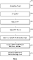
- FIG. 6 is a flow diagram 600 that illustrates an example process to transmit a data packet with NAT, arranged in accordance with at least some embodiments described herein.
- Example processes and methods may include one or more operations, functions or actions as illustrated by one or more of blocks 602, 604, 605, 606, 608, 610, and/or 610, and may in some embodiments be performed by network node such as an edge network device 802 of FIG. 8 .
- the operations described in blocks 602-612 may also be stored as computer-executable instructions in a computer-readable medium such as a memory 814 and/or a data storage 816 of edge network device 802.
- the example process to transmit a data packet with NAT begins with block 602 ("Receive Data Packet"), where a network appliance, such as a customer edge router receives a data packet to process.
- a network appliance such as a customer edge router receives a data packet to process.
- the customer edge router may be located at an edge of a carrier network that is being managed by a carrier, and may be configured to provide NAT functionality.
- the customer edge router may be one of multiple devices that collectively provide a virtualized CGN domain in a network function layer.
- Block 602 is followed by block 604 ("Perform NAT"), where the customer edge router performs NAT on the received data packet.
- the customer edge router translates the source IP address specified in the received data packet to its public IP address (e.g., the public IP address assigned to the customer edge router).
- Block 604 is followed by block 605 ("Maintain VRF"), where the customer edge router maintains a record of the address mapping and/or routing within a particular VPN for the data packet. For example, if the data packet is received from a computing device within a given VPN, the address of the computing device may be entered in the VRF
- Block 605 is followed by block 606 ("Maintain NAT Record"), where the customer edge router maintains a record of the address translation (e.g., mapping) of the private IP address to the public IP address.
- the customer edge router maintains the record of the address translation a NAT table.
- the customer edge router includes the VPN to which the data packet belongs in the record of the address translation.
- Block 606 is followed by block 608 ("Determine a Tunnel for the NAT'ed Data Packet"), where the customer edge router selects an appropriate tunnel to forward the NAT'ed data packet.
- the customer edge router selects an appropriate aggregation router to receive the NAT'ed data packet.
- the appropriate aggregation router may be an aggregation router in an aggregation platform layer that corresponds to the network function layer of the customer edge router.
- the customer edge router has established respective tunnels to the aggregation routers in the corresponding aggregation platform layer.
- Block 608 is followed by block 610 ("Encapsulate NAT'ed Data Packet with Overlay Information"), where the network node encapsulates the NAT'ed data packet with the overlay information corresponding to the selected tunnel.
- the overlay information may include a port address of the customer edge router and a port address of the aggregation router used to establish the selected tunnel.
- Block 610 is followed by block 612 ("Send Encapsulated NAT'ed Data Packet through Tunnel"), where the customer edge router sends the encapsulated NAT'ed data packet through the selected tunnel.
- the aggregation router at the other end of the selected tunnel may remove the overlay information from the encapsulated NAT'ed data packet and forward the de-encapsulated NAT'ed data packet to the specified destination.
- the aggregation router may maintain a record of the route (e.g., tunnel) through which the encapsulated NAT'ed data packet is received.
- the record may include the source IP address specified in the removed overlay information and the source IP address specified in the de-encapsulated NAT'ed data packet.
- FIG. 7 is a flow diagram 700 that illustrates an example process to transmit a return data packet corresponding to a NAT'ed data packet, arranged in accordance with at least some embodiments described herein.
- Example processes and methods may include one or more operations, functions or actions as illustrated by one or more of blocks 702, 704, 706, and/or 708, and may in some embodiments be performed by network node such as an edge network device 802 of FIG. 8 .
- the operations described in blocks 702-708 may also be stored as computer-executable instructions in a computer-readable medium such as a memory 814 and/or a data storage 816 of edge network device 802.
- the example process to transmit a return data packet corresponding to a NAT'ed data packet may begin with block 702 ("Receive Data Packet"), where a network appliance, such as an aggregation router may receive a data packet to process.
- a network appliance such as an aggregation router may receive a data packet to process.
- the aggregation router may be located at or near a public edge of a carrier network, and may be configured to direct network traffic to customer edge routers that may be providing a virtual CGN functionality.
- the aggregation router may be one of a number of devices in an aggregation platform layer.
- the aggregation router may determine from the destination IP address of the received data packet that the data packet is to be forwarded to a customer edge router in a function endpoint layer that corresponds to the aggregation platform layer.
- Block 702 may be followed by block 704 ("Determine a Tunnel for the Data Packet"), where the aggregation router may identify a tunnel through which to forward the data packet to an appropriate customer edge router. For example, the aggregation router may identify the tunnel based on the destination IP address specified in the received data packet and its routing table. The aggregation router may be maintaining a routing table whose entries identify the tunnel through which NAT'ed data packets are received from the function endpoint layer.
- Block 704 may be followed by block 706 ("Encapsulate the Data Packet with Overlay Information"), where the aggregation router may encapsulate the data packet with overlay information that corresponds to the identified tunnel.
- the overlay information may include a port address of the aggregation router and a port address of the customer edge router used to establish the identified tunnel.
- Block 706 may be followed by block 708 ("Send Encapsulated Data Packet through Tunnel"), where the aggregation router may send the encapsulated data packet through the identified tunnel.
- the customer edge router at the other end of the identified tunnel removes the overlay information from the encapsulated data packet.
- the customer edge router determines to perform a reverse NAT on the de-encapsulated data packet. For example, the customer edge router may determine that the destination IP address specified in the de-encapsulated data packet is its device address (e.g., the public device address of the customer edge router), and determine from this to perform a reverse NAT to correctly forward the de-encapsulated data packet to the proper destination.
- the customer edge router identifies the correct destination IP address (e.g., the private IP address) from its NAT table, and reverse NAT the destination IP address specified in the de-encapsulated data packet to create a reverse NAT'ed data packet.
- the customer edge router is maintaining a NAT table whose entries identify the mappings of the translations from a private IP address to its device address (e.g., the public IP address of the customer edge router).
- the customer edge router forwards the reverse NAT'ed data packet on its way to the destination address specified in reverse NAT'ed data packet.
- the customer edge router identifies a VPN associated with the return data packet and performs a lookup in the VRF table for the VPN to determine where the return data packet is to be routed.
- FIG. 8 illustrates an environment 800 of edge network device 802 that may be used to provide a virtualized network function through address space aggregation, arranged in accordance with at least some embodiments described herein.
- edge network device 802 that may include multiple potential connections for communicating with other edge network devices 804, 806, and 808.
- edge network device 802 may communicate with edge network device 804 using a network A 860, with edge network device 806 using a network B 870, and/or with edge network device 808 using a network C 880.
- Edge network devices 802, 804, 806, and 808 may be similar or comparable to aggregation routers 102a and 102b and customer edge routers 104a, 104b, 106a, and 106b of FIGS. 1-5 .
- Environment 800 may additionally include a client device 850 that may be communicatively coupled to edge network device 802, for example, across an external network domain.
- edge network device 802 may include a network A connection 820, a network B connection 830, and a network C connection 840. As illustrated by the ellipses below network C connection 840, any number of additional or other potential connections may also be included. In these and other embodiments, edge network device 802 may include multiple circuits for connecting to the one or more potential connections. For example, edge network device 802 may include a circuit A 822 and a circuit B 824 for network A connection 820, a circuit A 832 and a circuit B 834 for network B connection 830, and a circuit A 842 and a circuit B 844 for network C connection 840. In these and other embodiments, edge network device 802 may be configured to route traffic along one or more of the circuits, based on one or more policies stored by edge network device 802.
- edge network device 802 may be configured to monitor one or more properties of the various connections. For example, edge network device 802 may monitor the jitter, latency, loss, and/or bandwidth of the various communication links from edge network device 802 to edge network device 804, 806, and/or 808. In these and other embodiments, edge network device 802 may also monitor and/or store security properties of the various communication links. For example, links 862 and 864 over network A 860 may be considered at a first level of security, links 872 and 874 over network B 870 may be considered at a second level of security, and links 882 and 884 over network C 880 may be considered at a third level of security. In some embodiments, one or more of links 862, 864, 872, 874, 882, and/or 884 may be tunnels, such as GRE tunnels, IPsec tunnels, L2TP tunnels, and/or others.
- tunnels such as GRE tunnels, IPsec tunnels, L2TP tunnels, and/or others.
- edge network device 802 may be configured to route traffic to the various links based on the source of the traffic. For example, one or more policies may indicate that traffic from one corporate department of a business be routed along network B connection 830, while traffic for another corporate department may be routed along any link.
- edge network device 802 may include a processor 812, a memory 814, a storage device 816, and/or a communication device 818.
- processor 812 may include any suitable special-purpose or general-purpose computer, computing entity, or processing device including various computer hardware or software modules, and may be configured to execute instructions stored on any applicable computer-readable storage media.
- processor 812 may include a microprocessor, a microcontroller, a digital signal processor (DSP), an application-specific integrated circuit (ASIC), a Field-Programmable Gate Array (FPGA), or any other digital or analog circuitry configured to interpret and/or to execute program instructions and/or to process data.
- DSP digital signal processor
- ASIC application-specific integrated circuit
- FPGA Field-Programmable Gate Array
- processor 812 may include any number of processors distributed across any number of network or physical locations that are configured to perform individually or collectively any number of operations described in the present disclosure.
- processor 812 may interpret and/or execute program instructions and/or process data stored in memory 814, storage device 816, or memory 814 and storage device 816.
- processor 812 may fetch program instructions from data storage 816 and load the program instructions into memory 814. After the program instructions are loaded into memory 814, processor 812 may execute the program instructions.
- Memory 814 and storage device 816 may include computer-readable storage media or one or more computer-readable storage mediums for carrying or having computer-executable instructions or data structures stored thereon.
- Such computer-readable storage media may be any available media that may be accessed by a general-purpose or special-purpose computer, such as processor 812.
- edge network device 802 may or may not include either of memory 814 and storage device 816.
- such computer-readable storage media may include non-transitory computer-readable storage media including Random Access Memory (RAM), Read-Only Memory (ROM), Electrically Erasable Programmable Read-Only Memory (EEPROM), Compact Disc Read-Only Memory (CD-ROM) or other optical disk storage, magnetic disk storage or other magnetic storage devices, flash memory devices (e.g., solid state memory devices), or any other storage medium which may be used to carry or store desired program code in the form of computer-executable instructions or data structures and which may be accessed by a general-purpose or special-purpose computer. Combinations of the above may also be included within the scope of computer-readable storage media.
- Computer-executable instructions may include, for example, instructions and data configured to cause processor 812 to perform a certain operation or group of operations.
- Communication device 818 may include any component, device, system, or combination thereof that is configured to transmit or receive information. In some embodiments, communication device 818 may communicate with other devices at other locations, the same location, or even other components within the same system.
- communication device 818 may include a modem, a network card (wireless or wired), an optical communication device, a radio frequency transducer, an ultrasonic transducer, an infrared communication device, a wireless communication device (such as an antenna), and/or chipset (such as a Bluetooth device, an 802.6 device (e.g., Metropolitan Area Network (MAN)), a WiFi device, a WiMax device, cellular communication facilities, or others), and/or the like, and/or combinations thereof.
- MAN Metropolitan Area Network
- Communication device 818 may permit data to be exchanged with a network and/or any other devices or systems described in the present disclosure.
- communication device 818 may allow edge network device 802 to communicate with other systems, such as any one or more of edge network devices 804, 806, and 808.
- environment 800 of FIG. 8 may include any number of edge network devices.
- environment 800 may include three communication networks (network A 860, network B 870, and network C 880) any number of communication networks may be utilized.
- embodiments described in the present disclosure may include the use of a special purpose or general purpose computer (e.g., processor 812 of FIG. 8 ) including various computer hardware or software modules, as discussed in greater detail herein. Further, as indicated above, embodiments described in the present disclosure may be implemented using computer-readable media (e.g., memory 814 of FIG. 8 ) for carrying or having computer-executable instructions or data structures stored thereon.
- a special purpose or general purpose computer e.g., processor 812 of FIG. 8
- computer-readable media e.g., memory 814 of FIG. 8
- module or “component” may refer to specific hardware implementations configured to perform the actions of the module or component and/or software objects or software routines that may be stored on and/or executed by general purpose hardware (e.g., computer-readable media, processing devices, etc.) of the computing system.
- general purpose hardware e.g., computer-readable media, processing devices, etc.
- the different components, modules, engines, and services described in the present disclosure may be implemented as objects or processes that execute on the computing system (e.g., as separate threads). While some of the system and methods described in the present disclosure are generally described as being implemented in software (stored on and/or executed by general purpose hardware), specific hardware implementations, firmware implements, or any combination thereof are also possible and contemplated.
- a "computing entity” may be any computing system as previously described in the present disclosure, or any module or combination of modulates executing on a computing system.
Description
- The present disclosure relates generally to network communications.
- Presently, there is a growing movement among enterprises and other entities towards cloud architectures. One consequence of this movement is that enterprise customers are demanding more managed services, such as connectivity and security services (e.g., secure connectivity and transmission of data, firewall services, and the like), from their network service providers.
- The subject matter claimed in the present disclosure is not limited to embodiments that solve any disadvantages or that operate only in environments such as those described above. Rather, this background is only provided to illustrate one example technology area where some embodiments described in the present disclosure may be practiced.
- Cui Y et al.: "Lightweight 4over6: An Extension to the Dual-Stack Lite Architecture; rfc7596.txt"; RFC7596, IETF; ISOC, 4 Rue Des Falaises, 1205 Geneva, Switzerland, 31 July 2015, pages 1-22, XP015107650, describes an architecture for transporting IPv4 packets over an IPv6 network including an extension to DS-Lite called "Lightweight 4over6", which moves the Network Address and Port Translation (NAPT) function from the centralized DS-Lite tunnel concentrator to the tunnel client located in the Customer Premises Equipment (CPE). This removes the requirement for a Carrier Grade NAT function in the tunnel concentrator and reduces the amount of centralized state that must be held to a per-subscriber level.
- Aspects of the invention are set out in the independent claims and preferred features are set out in the dependent claims. Features of one aspect may be applied to each aspect alone or in combination with other aspects.
- According to some examples, methods to provide a virtualized Carrier-grade Network Address Translation (CGN) at a customer edge router of multiple customer edge routers are described. The invention is defined in the independent claims.
- The objects and advantages of the embodiments will be realized and achieved at least by the elements, features, and combinations particularly pointed out in the claims. Both the foregoing general description and the following detailed description are given as examples, are explanatory and are not restrictive of the invention, as claimed.
- The foregoing and other features of this disclosure will become more fully apparent from the following description and appended claims, taken in conjunction with the accompanying drawings. Understanding that these drawings depict only several embodiments in accordance with the disclosure and are, therefore, not to be considered limiting of its scope, the disclosure will be described with additional specificity and detail through use of the accompanying drawings, in which:
-
FIG. 1 illustrates an overview of an environment and devices on which an architecture of the present disclosure may operate; -
FIG. 2 illustrates an example address space management in the architecture ofFIG. 1 ; -
FIG. 3 illustrates an example address and function assignments of selected devices in the architecture ofFIG. 1 ; -
FIG. 4 is a sequence diagram that illustrates an example network traffic flow; -
FIG. 5 is a sequence diagram that illustrates an example return network traffic flow; -
FIG. 6 is a flow diagram that illustrates an example process to transmit a data packet with NAT; -
FIG. 7 is a flow diagram that illustrates an example process to transmit a return data packet corresponding to a NAT'ed data packet; and -
FIG. 8 illustrates an environment of an edge network device that may be used to provide a virtualized network function through address space aggregation,
all arranged in accordance with at least some embodiments described herein. - In the following detailed description, reference is made to the accompanying drawings, which form a part hereof. In the drawings, similar symbols typically identify similar components, unless context dictates otherwise. The illustrative embodiments described in the detailed description and the drawings are not meant to be limiting. The invention is defined by the independent claims. Other embodiments may be utilized, and other changes may be made. The aspects of the present disclosure, as generally described herein, and illustrated in the Figures, can be arranged, substituted, combined, separated, and designed in a wide variety of different configurations within the scope of the claims.
- This disclosure is generally drawn, inter alia, to methods, apparatus, systems, devices, and/or computer program products related to allowing multiple, distributed network nodes to participate in and enable one or more managed services (interchangeably referred to herein as "network functions" or "functions") that would typically be delivered using a small number of centralized, large scale network appliances.
- As discussed above, enterprises are demanding more managed services from their network service providers. In providing the managed services to an enterprise, a network service provider (interchangeably referred to herein as a "network carrier" or "carrier") may employ an aggregation layer that includes a small number of centralized network nodes or aggregation nodes. The network service provider may place an enterprise customer on one side of the aggregation layer, and the network infrastructure that is outside of the enterprise customer, such as the Internet, on the other side of the aggregation layer. The network service provider may direct all network traffic between the enterprise customer and the network infrastructure outside the enterprise customer through the aggregation layer. That is, all network traffic into and out of the carrier network travels through the small number of centralized aggregation nodes in the aggregation layer.
- For example, a carrier may employ a small number of centralized peering routers or provider edge routers (interchangeably referred to herein as "aggregation nodes" or "aggregation routers") in the aggregation layer, and place the small number of centralized aggregation routers at or near the public edge of the carrier network. The carrier may also employ and manage multiple routers (e.g., customer edge routers) at the edge of the carrier network where the enterprise customer connects to the carrier network. For example, the customer edge routers may be located at the various location or premises of the enterprise customer. The customer edge routers may connect to the provider edge of the carrier, for example, the aggregation routers, and may be the last points of the carrier. The carrier may advertise a public address using the aggregation routers, thus directing the network traffic to the carrier network through the aggregation routers. The carrier may provide the appropriate routing between the aggregation routers and the customer edge routers. As all network traffic into and out of the carrier network passes through the small number of centralized aggregation routers, the carrier may provide the managed services at the small number of centralized aggregation routers. The carrier is also able to control the route of the return network traffic (e.g., get more network traffic to pass through the carrier network).
- However, using a small number of centralized aggregation routers presents scalability issues in that the small number of nodes have to maintain a very large, and maybe significant amount of information. For example, the carrier may provide Carrier-grade Network Address Translation (CGN) at the aggregation routers to direct and control the network traffic into and out of the carrier network through the aggregation routers. CGN is an approach where the carrier is able to provide the customer edge routers (e.g., the enterprise customer) private addresses, bring the network traffic from the customer edge routers to the small number of aggregation routers, and translate the private network address to public addresses of the aggregation routers (e.g., the public address advertised by the aggregation routers) at the aggregation routers. The aggregation routers may perform a "reverse" translation for the return network traffic to the customer edge routers. This may require the small number of aggregation routers to maintain a very large, and maybe significant amount of state information as the aggregation routers may be providing CGN for a very large number of network addresses (e.g., network nodes). This may present scalability issues. In addition, a failure of an aggregation router may have a significant impact (e.g., affect a very large number of network nodes) as the aggregation router may be serving hundreds or thousands of customers.
- The present disclosure generally describes any number of distributed network nodes participating in and enabling one or more network functions that would typically be delivered using a small number of centralized aggregation nodes. In some embodiments, multiple customer edge routers may use a combination of distributed processing and address space aggregation across a carrier network domain where a network function is to be provided to deliver the network function in a virtualized manner.
- For the purpose of providing an example, CGN function will be described as an example of a virtualized network function. Those of ordinary skill in the art will appreciate that other network functions, such as firewalls, content inspection and filtering, customer premises equipment (CPE), and the like, may be similarly provided in a virtualized manner as described herein with respect to CGN. Another example of such a network function may include virtual private networking (VPN) and associated address mapping when transporting packets from and/or to one or more VPNs.
- In some embodiments, a virtualized CGN function may be provided on an architecture that includes an aggregation platform layer, a function endpoint layer, and an aggregated or functional Internet Protocol (IP) address space. The aggregation platform layer may include one or more aggregation routers. The aggregation platform layer may terminate the tunnels from the function endpoint layer to act as a gateway between an outside network (e.g., the Internet) and the devices performing the virtualized CGN function. The aggregation platform layer may also advertise an aggregated IP address space. The advertised aggregated IP address space may provide return routability to the function endpoint layer such that the function endpoint layer appears to be on a carrier network that is providing the virtualized CGN function.
- The function endpoint layer may include the devices that perform the Network Address Translation (NAT) to collectively form a virtualized CGN carrier network (e.g., virtualized CGN domain). The virtualized CGN carrier network may be accessible through the aggregation platform layer. The function endpoint layer may include one or more customer edge routers. Each customer edge router may establish a tunnel to each aggregation router in the aggregation platform layer to establish an overlay network.
- The aggregated IP address space may be assigned to the customer edge routers in the function endpoint layer as individual IP addresses, for example, on the connections facing the carrier network. In instances where a customer edge router resides in multiple carrier networks, the aggregated IP address space may be assigned to the customer edge router as a logical loopback address. The aggregated IP address space may be assigned by the carrier, and advertised from the aggregation routers in the aggregation platform layer. In some embodiments, the agrregated IP address space may be carrier independent. One benefit of this architecture is that the customer edge routers in the function endpoint may reside in any carrier domain (e.g., carrier network), and be logically tied to the carrier that is providing (managing) the virtualized CGN function.
- In some embodiments, each aggregation router may advertise an aggregated IP address space. The aggregated IP address space includes the IP addresses assigned to the customer edge routers. Each customer edge router performs the NAT using its assigned IP address. Each customer edge router establishes a tunnel with each aggregation router. Suitable protocols for establishing a tunnel include, by way of example, Generic Routing Encapsulation (GRE), Internet Protocol Security (IPsec), Layer 2 Tunneling Protocol (L2TP), and/or others.
- Upon receiving a data packet (e.g., network traffic) that is subject to NAT (e.g., network traffic from the enterprise customer), the customer edge router performs the NAT of the data packet (e.g. using the IP address assigned to the customer edge router), encapsulates the NAT'ed data packet with overlay information of a tunnel to a specific aggregation router, and sends the encapsulated data packet to the specific aggregation router through the tunnel. At the other end of the tunnel, the specific aggregation router may remove the overlay information, maintain a record of the tunnel through which the data packet is received, and forward the de-encapsulated data packet to the specified destination. For example, the specific aggregation router may maintain the record of the tunnel through which the data packet was received in a routing table.
- The customer edge router performs VPN mapping. When receiving a data packet from a VPN, when performing the NAT of the data packet, the customer edge router identifies the VPN with which the data packet is associated. Additionally, the customer edge router maintains a Virtual Routing & Forwarding (VRF) table that identifies which addresses are to be routed within the particular VPN. For example, the customer edge router may store a route target for the route distinguishers to identify the VPN. The NAT performed on the data packet may address VPN routing such that the specific aggregation router does not store any VPN information. Embodiments of the present disclosure may provide an arrangement such that an enterprise may acquire a data link to a provider (e.g., Verizon or Comcast) and may obtain VPN services via the customer edge routers rather than the provider edge router.
- When an aggregation router receives a return data packet (e.g., return network traffic), the aggregation router may forward the return data packet to a specific (e.g., correct) customer edge router based on the addressing information in the return data packet. For example, the destination address specified in the return data packet may be that of an address in the aggregated IP address space. As this is a return data packet, the source and destination addresses in the return data packet may be the "reverse" of the source and destination addresses in the original, NAT'ed data packet. That is, the original, NAT'ed source address is now the destination address in the return data packet, and the original destination address is now the source address in the return data packet. The aggregation router may identify a specific customer edge router, and the tunnel established with the specific customer edge router, based on the previously maintained record of the tunnels through which it received the NAT'ed data packets. The aggregation router may encapsulate the return data packet with overlay information of the tunnel to the identified customer edge router, and send the encapsulated return data packet to the identified customer edge router through the tunnel. At the other end of the tunnel, the specific customer edge router removes the overlay information, performs a reverse translation (e.g., reverse NAT) of the return data packet, and forwards the de-encapsulated, reverse translated return data packet to the specified destination.
- When the customer edge router receives the return data packet to perform the reverse NAT, the customer edge router additionally performs VPN mapping. The NAT table identifies to which VPN the return data packet is directed to. The VRF table of that VPN identifies where the return data packet is to be routed within the VPN.
- As described above, in some embodiments, the architecture provides for construction of a virtual CGN function by allowing each customer edge router to perform the NAT of the network traffic, using the aggregation routers as entry and exit points to the NAT function, and routing the network traffic in an overlay network using tunnels between each customer edge router and the aggregation routers. One benefit provided by the architecture is that any scaling issue is greatly minimized. For example, as the scale of the virtual CGN may be limited by the amount of network traffic and/or the number of tunnels that may be supported by any one aggregation router, this scale issue may be readily addressed by clustering customer edge routers around additional aggregation routers.
- Moreover, as each customer edge router is performing the NAT function, each customer edge router maintains the state information for the network traffic NAT performed by the customer edge router. The aggregation routers do not maintain any NAT state information. As there may be many customer edge routers performing the NAT function and each customer edge router is serving a single customer, failure of an aggregation router or any customer edge router at most affects the state information maintained by the failing router. Accordingly, one benefit is that the architecture described herein is very resilient in that a failure will likely have a small impact (e.g., affect a small number of network nodes).
- Embodiments of the present disclosure are explained with reference to the accompanying drawings.
-
FIG. 1 illustrates an overview of anenvironment 100 and devices on which an architecture of the present disclosure may operate, arranged in accordance with at least some embodiments described herein.Environment 100 may include afunction provider domain 102,network provider domains outside network 108.Function provider domain 102,network provider domain 104, andnetwork provider domain 106 may be a carrier network provided and managed by a carrier such as Verizon, AT&T, Sprint, Comcast, and the like.Outside network 108 may include any network infrastructure, such as the Internet, one or more connected public networks, and the like, that is external to an enterprise customer.Function provider domain 102,network provider domains network 108 may each be logically connected to the other bycommunication links 110a-110e.Communication links 110a-110e may be interprovider (e.g., intercarrier) links. -
Function provider domain 102 may provide the aggregation platform layer functionality.Function provider domain 102 may include a small number of network appliances, such asaggregation routers Aggregation routers Function provider domain 102 may operate or function as a gateway betweennetwork provider domains outside network 108. -
Network provider domains Network provider domains network provider domain 104 andnetwork provider domain 106, respectively) where an enterprise customer connects to the carrier network. As depicted,network provider domain 104 may includecustomer edge routers Network provider domain 106 may includecustomer edge routers - In some embodiments, the
network provider domain 104 may establish an overlay network with thefunction provider domain 102. For example, eachcustomer edge router aggregation router customer edge routers aggregation routers tunnel 112a may be established betweencustomer edge router 104a andaggregation router 102a, atunnel 112b may be established betweencustomer edge router 104a andaggregation router 102b, atunnel 112c may be established betweencustomer edge router 104b andaggregation router 102a, atunnel 112d may be established between customer edge router 104d andaggregation router 102b, atunnel 112e may be established betweencustomer edge router 106a andaggregation router 102a, atunnel 112f may be established betweencustomer edge router 106a andaggregation router 102b, atunnel 112g may be established betweencustomer edge router 106b andaggregation router 102a, and atunnel 112h may be established between customer edge router 106d andaggregation router 102b. In some embodiments, an abstraction mechanism other than tunnels, may be used to provide the logical reference and connection between thenetwork provider domain 104 and thefunction provider domain 102. - In some embodiments,
function provider domain 102 andnetwork provider domains function provider domain 102 andnetwork provider domains network provider domain 104 to service the first enterprise customer location andnetwork provider domain 106 to service the second enterprise customer location). That is, Verizon may have sufficient network circuits to support both enterprise customer locations. As a result,function provider domain 102 andnetwork provider domains customer edge routers customer edge routers customer edge routers customer edge routers - In some embodiments, one or more network provider domains (e.g.,
network provider domain 104 and/or network provider domain 106) may be provided by a carrier that is different than the carrier providingfunction provider domain 102. That is,function provider domain 102 may be a first carrier network provided and managed by a first carrier, and one or more network provider domains (e.g.,network provider domain 104 and/or network provider domain 106) may be a second carrier network provided and managed by a second carrier. Continuing the Verizon example above, Verizon may be able to support the first enterprise customer location but not the second enterprise customer location. That is, Verizon may have the infrastructure (e.g., network circuits) to support the first enterprise customer location, but lack (e.g., not have) the infrastructure to support the second enterprise customer location. In this instance, Verizon may lease the necessary network circuits from a carrier that has the infrastructure to support the second enterprise customer location. For example, assuming that Comcast has the infrastructure to support the second enterprise customer location, Verizon may lease the necessary network circuits from Comcast to support the second enterprise customer location. As a result,function provider domain 102 andnetwork provider domain 104 may be a Verizon network to service the first customer location, andnetwork provider domain 106 may be a Comcast network to service the second enterprise customer location. Verizon is only leasing the Comcast network circuits to support the second enterprise customer location. Verizon is managing the enterprise customer networks at both the first enterprise customer location and the second enterprise customer location. Accordingly, Verizon may placecustomer edge routers customer edge routers customer edge routers customer edge routers customer edge routers customer edge routers - Modifications, additions, or omissions may be made to
FIG. 1 without departing from the scope of the present disclosure. For example, while illustrated as including two provider edge routers,function provider domain 102 may include a different number of aggregation routers. As another example, while illustrated as including two customer edge routers, each or both ofnetwork provider domains 104 and/or 106 may include any number of customer edge routers, such as hundreds of customer edge routers. As still another example, there may be a different number of network provider domains, such as tens or possibly hundreds, based on the number of enterprise customer locations. Moreover, multiple carriers in addition to the carrier providing the carrier network for the function provider domain may be providing the carrier networks for some of the network provider domains. -
FIG. 2 illustrates an example address space management in the architecture ofFIG. 1 , arranged in accordance with at least some embodiments described herein. The architecture ofFIG. 2 is substantially similar to the architecture ofFIG. 1 , with additional details. Those components inFIG. 2 that are labelled identically to components ofFIG. 1 will not be described again for the purposes of clarity. More specifically,FIG. 2 illustrates an example assignment of an aggregated IP address space of the aggregation platform layer to the function endpoint layer as individual public IP addresses. The individual public IP addresses are specific IP addresses in the aggregated IP address space. In some embodiments, a carrier that is providingfunction provider domain 102 may assign an aggregated IP address space to the aggregation routers (e.g.,aggregation routers function provider domain 102. The aggregated IP address space may be a block of public IP addresses belonging to the carrier. The carrier may assign a specific host IP address from the aggregated IP address space to each customer edge router (e.g.,customer edge routers function provider domain 102. Each customer edge router in the function endpoint layer may be configured to perform NAT using the assigned host IP address. - Referring again the Verizon example above, and as illustrated in
FIG. 2 , aggregated IP address space 11.1.1.0/24 may be a block of public IP addresses belonging to Verizon. Verizon may assign the block of public IP addresses toaggregation routers customer edge router 104a, public IP address 11.1.1.2/32 tocustomer edge router 104b, public IP address 11.1.1.3/32 tocustomer edge router 106a, and public IP address 11.1.1.4/32 tocustomer edge router 106b. Even in the example above where Comcast is providingnetwork provider domain 106, Verizon may assign specific public IP addresses from the aggregated IP address space tocustomer edge routers -
FIG. 3 illustrates an example address and function assignments of selected devices in the architecture ofFIG. 1 , arranged in accordance with at least some embodiments described herein.Customer edge router 104a may establishtunnel 112a toaggregation router 102a. For example,tunnel 112a may be logically connected to port address 13.1.1.1 atcustomer edge router 104a, and port address 15.1.1.1 ataggregation router 102a.Tunnel 112a provides an overlay.Provider edge router 102a may be configured to advertise the aggregated IP address space assigned to functionprovider domain 102 to the public. For example,provider edge router 102 may advertise the IP address prefix 11.1.1.0/24 tooutside network 108.Customer edge router 104a may be configured to perform NAT of data packets using the specific host IP address assigned tocustomer edge router 104. The specific host IP address is a public IP address included in the aggregated IP address space. For example,customer edge router 104a may perform NAT using host IP address 11.1.1.1/32. Performing NAT using its host address and using the overlay toaggregation router 102a allowscustomer edge router 104a to retain visibility of return network traffic even in instances where the circuit is being provided by a different carrier. That is, the return network traffic is able to come back tocustomer edge router 104a. -
FIG. 4 is a sequence diagram that illustrates an example network traffic flow, arranged in accordance with at least some embodiments described herein. As depicted, the network traffic flow may be from a source, for example, aclient device 402, to a destination, for example, aclient device 404.Client device 402 may have a private IP address 10.1.1.1, andclient device 404 may have a private IP address 12.1.1.1.Client device 402 may send or transmit a data packet 406, which specifies a source IP address 10.1.1.1:05 and a destination IP address 12.1.1.1 (e.g., from port :05). Data packet 406 may also include other information. -
Customer edge router 104a receives data packet 406 and determines to perform NAT on data packet 406. For example,customer edge router 104a may make a determination to perform NAT based on local configuration and/or one or more applicable policies. Having determined to perform NAT on data packet 406,customer edge router 104a translates the private source IP address 10.1.1.1:05 to public IP address 11.1.1.1, which is the device IP address assigned tocustomer edge router 104a. The NAT'ed data packet may specify a new source IP address 11.1.1.1 and the destination IP address 12.1.1.1. Customer edge router maintains a record of the mapping of private IP address 10.1.1.1:05 to public IP address 11.1.1.1, for example, in a NAT mapping table. - Additionally, the
customer edge router 104a maintains a virtual routing and forwarding (VRF) table. For example, the enterprise associated withcustomer edge router 104a may operate multiple VPNs, each with their own VRF. Based on which VPN the data packet is received from, thecustomer edge router 104a creates an entry in the NAT table identifying to which VPN the data packet belongs. As illustrated inFIG. 4 , the data packet 406 may come from VPN_1. Thecustomer edge router 104a additionally creates an entry in the VRF table for VPN_1 that identifies that data packets directed to the address 10.1.1.1 are to be out of Interface_1 of thecustomer edge router 104a. - In some embodiments, a range of addresses may be assigned to a given customer such that one or more VPNs of the customer may be given a specific IP address within the range of addresses. In these and other embodiments, the range of addresses may cover the number of VPNs an organization may utilize.
-
Customer edge router 104a then determines that the NAT'ed data packet is to be sent toaggregation router 102a. For example,customer edge router 104a may select the appropriate aggregation router to receive the NAT'ed data packet based on local configuration and/or one or more applicable policies. Having selectedaggregation router 102a,customer edge router 104a encapsulates the NAT'ed data packet with overlay information that corresponds to (e.g., identifies)tunnel 112a. For example, the overlay information may include an overlay header that specifies a source port address oftunnel 112a, 13.1.1.1, and a destination port address oftunnel 112a, 15.1.1.1. An encapsulated andNAT'ed data packet 408 may specify a source IP address 11.1.1.1 and a destination IP address 12.1.1.1, and include an overlay header that specifies a source port address 13.1.1.1 and a destination port address 15.1.1.1.Customer edge router 104a sends encapsulated andNAT'ed data packet 408 throughtunnel 112a toaggregation router 102a. Encapsulated andNAT'ed data packet 408 may also include other information. -
Aggregation router 102a may receive encapsulated andNAT'ed data packet 408, for example, at the other end oftunnel 112a.Aggregation router 102a may remove the overlay header, source port address 13.1.1.1 and destination port address 15.1.1.1, from encapsulated andNAT'ed data packet 408 to generate ade-encapsulated data packet 410.De-encapsulated data packet 410 may specify the source IP address 11.1.1.1 and the destination IP address 12.1.1.1. From the overlay header,aggregation router 102a may identifytunnel 112a as the tunnel through which encapsulated andNAT'ed data packet 408 is received.Aggregation router 102a may maintain a record that encapsulated andNAT'ed data packet 408 is received throughtunnel 112a, for example, in a routing table. For example, the record may indicate that IP address 11.1.1.1 (e.g., the source IP address specified in de-encapsulated data packet 410) is routed to IP address 13.1.1.1 (e.g., the source port address specified in the overlay header).Aggregation router 102a may use this record to correctly route the return network traffic tocustomer edge router 104a.Aggregation router 102a may sendde-encapsulated data packet 410 on its way toclient device 404. For example,de-encapsulated data packet 410 may be sent to itsdestination client device 404 throughoutside network 108. -
FIG. 5 is a sequence diagram that illustrates an example return network traffic flow, arranged in accordance with at least some embodiments described herein. The return network traffic flow may be from a client device, for example,client device 404, to a client device, for example,client device 402. For example, the return network flow may be a response to previously transmitted data packet or data packets fromclient device 402 toclient device 404.Client device 404 may have a private IP address 12.1.1.1, andclient device 402 may have a private IP address 10.1.1.1.Client device 404 may send or transmit adata packet 502, which specifies a source IP address 12.1.1.1 and a destination IP address 11.1.1.1.Data packet 502 may also include other information. -
Aggregation router 102a may receivedata packet 502, for example, throughoutside network 108.Aggregation router 102a may determine thatdata packet 502 is to be forwarded to a network appliance, such as a customer edge router, in the corresponding function endpoint layer.Aggregation router 102a may make the determination based on the destination IP address specified indata packet 502. For example,aggregation router 102a may determine that the destination IP address 11.1.1.1 specified indata packet 502 is an individual public IP address in the aggregated IP address 11.1.1.0/24 assigned toaggregation router 102a.Aggregation router 102a may identify the appropriate tunnel to forwarddata packet 502 based on the destination IP address specified indata packet 502 and its routing table. For example,aggregation router 102a may determine from its routing table that IP address 11.1.1.1 (e.g., the destination IP address specified in data packet 502) is to be forwarded through a tunnel established with port address 13.1.1.1.Aggregation router 102a may encapsulatedata packet 502 with overlay information that corresponds to (e.g., identifies)tunnel 112a (e.g., the tunnel to port address 13.1.1.1). For example, the overlay information may include an overlay header that specifies a source port address oftunnel 112a, 15.1.1.1, and a destination port address oftunnel 112a, 13.1.1.1. An encapsulateddata packet 504 may specify a source IP address 12.1.1.1 and a destination IP address 11.1.1.1, and include an overlay header that specifies a source port address 15.1.1.1 and a destination port address 13.1.1.1.Aggregation router 102a may send encapsulateddata packet 504 throughtunnel 112a tocustomer edge router 104a. Encapsulateddata packet 504 may also include other information. -
Customer edge router 104a receives encapsulateddata packet 504, for example, at the other end oftunnel 112a.Customer edge router 104a removes the overlay header, source port address 15.1.1.1 and destination port address 13.1.1.1, from encapsulateddata packet 504 tode-encapsulate data packet 504.Customer edge router 104a determines to perform a reverse NAT on the de-encapsulated data packet.Customer edge router 104a makes a determination to perform a reverse NAT based on the destination IP address specified in the de-encapsulated data packet.Customer edge router 104a determines from its NAT table that private IP address 10.1.1.1:05 was translated to public IP address 11.1.1.1 (e.g., the destination IP address specified in the de-encapsulated data packet).Customer edge router 104a reverse translates the public destination IP address 11.1.1.1 in the de-encapsulated data packet to private IP address 10.1.1.1:05 to generate a reverseNAT'ed data packet 506. ReverseNAT'ed data packet 506 may specify the source IP address 12.1.1.1 and a new destination IP address 10.1.1.1:05. ReverseNAT'ed data packet 506 may also include other information.Customer edge router 104a sends reverseNAT'ed data packet 506 on its way to the destination address specified in reverse NAT'ed data packet 506 (e.g., client device 402). - Additionally, the
customer edge router 104a observes from the NAT table that the destination address 10.1.1.1:05 is associated with VPN_1. Thecustomer edge router 104a accordingly looks up the address 10.1.1.1:05 in the VRF table associated with VPN_1. In these and other embodiments, thecustomer edge router 104a routes the reverseNAT'ed data packet 506 based on the VRF table (routes the packet through Interface_1). -
FIG. 6 is a flow diagram 600 that illustrates an example process to transmit a data packet with NAT, arranged in accordance with at least some embodiments described herein. Example processes and methods may include one or more operations, functions or actions as illustrated by one or more ofblocks edge network device 802 ofFIG. 8 . The operations described in blocks 602-612 may also be stored as computer-executable instructions in a computer-readable medium such as amemory 814 and/or adata storage 816 ofedge network device 802. - As depicted by flow diagram 600, the example process to transmit a data packet with NAT begins with block 602 ("Receive Data Packet"), where a network appliance, such as a customer edge router receives a data packet to process. For example, the customer edge router may be located at an edge of a carrier network that is being managed by a carrier, and may be configured to provide NAT functionality. The customer edge router may be one of multiple devices that collectively provide a virtualized CGN domain in a network function layer.
-
Block 602 is followed by block 604 ("Perform NAT"), where the customer edge router performs NAT on the received data packet. The customer edge router translates the source IP address specified in the received data packet to its public IP address (e.g., the public IP address assigned to the customer edge router). -
Block 604 is followed by block 605 ("Maintain VRF"), where the customer edge router maintains a record of the address mapping and/or routing within a particular VPN for the data packet. For example, if the data packet is received from a computing device within a given VPN, the address of the computing device may be entered in the VRF -
Block 605 is followed by block 606 ("Maintain NAT Record"), where the customer edge router maintains a record of the address translation (e.g., mapping) of the private IP address to the public IP address. The customer edge router maintains the record of the address translation a NAT table. The customer edge router includes the VPN to which the data packet belongs in the record of the address translation. -
Block 606 is followed by block 608 ("Determine a Tunnel for the NAT'ed Data Packet"), where the customer edge router selects an appropriate tunnel to forward the NAT'ed data packet. The customer edge router selects an appropriate aggregation router to receive the NAT'ed data packet. The appropriate aggregation router may be an aggregation router in an aggregation platform layer that corresponds to the network function layer of the customer edge router. The customer edge router has established respective tunnels to the aggregation routers in the corresponding aggregation platform layer. -
Block 608 is followed by block 610 ("Encapsulate NAT'ed Data Packet with Overlay Information"), where the network node encapsulates the NAT'ed data packet with the overlay information corresponding to the selected tunnel. The overlay information may include a port address of the customer edge router and a port address of the aggregation router used to establish the selected tunnel. -
Block 610 is followed by block 612 ("Send Encapsulated NAT'ed Data Packet through Tunnel"), where the customer edge router sends the encapsulated NAT'ed data packet through the selected tunnel. The aggregation router at the other end of the selected tunnel may remove the overlay information from the encapsulated NAT'ed data packet and forward the de-encapsulated NAT'ed data packet to the specified destination. The aggregation router may maintain a record of the route (e.g., tunnel) through which the encapsulated NAT'ed data packet is received. For example, the record may include the source IP address specified in the removed overlay information and the source IP address specified in the de-encapsulated NAT'ed data packet. - Those skilled in the art will appreciate that, for this and other processes and methods disclosed herein, the functions performed in the processes and methods may be implemented in differing order. Furthermore, the outlined actions and operations are only provided as examples, and some of the actions and operations may be optional, combined into fewer actions and operations, or expanded into additional actions and operations without detracting from the essence of the disclosed embodiments.
-
FIG. 7 is a flow diagram 700 that illustrates an example process to transmit a return data packet corresponding to a NAT'ed data packet, arranged in accordance with at least some embodiments described herein. Example processes and methods may include one or more operations, functions or actions as illustrated by one or more ofblocks edge network device 802 ofFIG. 8 . The operations described in blocks 702-708 may also be stored as computer-executable instructions in a computer-readable medium such as amemory 814 and/or adata storage 816 ofedge network device 802. - As depicted by flow diagram 700, the example process to transmit a return data packet corresponding to a NAT'ed data packet may begin with block 702 ("Receive Data Packet"), where a network appliance, such as an aggregation router may receive a data packet to process. For example, the aggregation router may be located at or near a public edge of a carrier network, and may be configured to direct network traffic to customer edge routers that may be providing a virtual CGN functionality. The aggregation router may be one of a number of devices in an aggregation platform layer. The aggregation router may determine from the destination IP address of the received data packet that the data packet is to be forwarded to a customer edge router in a function endpoint layer that corresponds to the aggregation platform layer.
-
Block 702 may be followed by block 704 ("Determine a Tunnel for the Data Packet"), where the aggregation router may identify a tunnel through which to forward the data packet to an appropriate customer edge router. For example, the aggregation router may identify the tunnel based on the destination IP address specified in the received data packet and its routing table. The aggregation router may be maintaining a routing table whose entries identify the tunnel through which NAT'ed data packets are received from the function endpoint layer. -
Block 704 may be followed by block 706 ("Encapsulate the Data Packet with Overlay Information"), where the aggregation router may encapsulate the data packet with overlay information that corresponds to the identified tunnel. The overlay information may include a port address of the aggregation router and a port address of the customer edge router used to establish the identified tunnel. -
Block 706 may be followed by block 708 ("Send Encapsulated Data Packet through Tunnel"), where the aggregation router may send the encapsulated data packet through the identified tunnel. The customer edge router at the other end of the identified tunnel removes the overlay information from the encapsulated data packet. The customer edge router determines to perform a reverse NAT on the de-encapsulated data packet. For example, the customer edge router may determine that the destination IP address specified in the de-encapsulated data packet is its device address (e.g., the public device address of the customer edge router), and determine from this to perform a reverse NAT to correctly forward the de-encapsulated data packet to the proper destination. The customer edge router identifies the correct destination IP address (e.g., the private IP address) from its NAT table, and reverse NAT the destination IP address specified in the de-encapsulated data packet to create a reverse NAT'ed data packet. The customer edge router is maintaining a NAT table whose entries identify the mappings of the translations from a private IP address to its device address (e.g., the public IP address of the customer edge router). The customer edge router forwards the reverse NAT'ed data packet on its way to the destination address specified in reverse NAT'ed data packet. - Additionally, the customer edge router identifies a VPN associated with the return data packet and performs a lookup in the VRF table for the VPN to determine where the return data packet is to be routed.
-
FIG. 8 illustrates anenvironment 800 ofedge network device 802 that may be used to provide a virtualized network function through address space aggregation, arranged in accordance with at least some embodiments described herein. As depicted,edge network device 802 that may include multiple potential connections for communicating with otheredge network devices edge network device 802 may communicate withedge network device 804 using anetwork A 860, withedge network device 806 using a network B 870, and/or withedge network device 808 using anetwork C 880.Edge network devices aggregation routers customer edge routers FIGS. 1-5 .Environment 800 may additionally include a client device 850 that may be communicatively coupled toedge network device 802, for example, across an external network domain. - In some embodiments,
edge network device 802 may include anetwork A connection 820, anetwork B connection 830, and anetwork C connection 840. As illustrated by the ellipses belownetwork C connection 840, any number of additional or other potential connections may also be included. In these and other embodiments,edge network device 802 may include multiple circuits for connecting to the one or more potential connections. For example,edge network device 802 may include acircuit A 822 and acircuit B 824 fornetwork A connection 820, acircuit A 832 and acircuit B 834 fornetwork B connection 830, and acircuit A 842 and acircuit B 844 fornetwork C connection 840. In these and other embodiments,edge network device 802 may be configured to route traffic along one or more of the circuits, based on one or more policies stored byedge network device 802. - In some embodiments,
edge network device 802 may be configured to monitor one or more properties of the various connections. For example,edge network device 802 may monitor the jitter, latency, loss, and/or bandwidth of the various communication links fromedge network device 802 to edgenetwork device edge network device 802 may also monitor and/or store security properties of the various communication links. For example,links network A 860 may be considered at a first level of security, links 872 and 874 over network B 870 may be considered at a second level of security, andlinks network C 880 may be considered at a third level of security. In some embodiments, one or more oflinks - In some embodiments,
edge network device 802 may be configured to route traffic to the various links based on the source of the traffic. For example, one or more policies may indicate that traffic from one corporate department of a business be routed alongnetwork B connection 830, while traffic for another corporate department may be routed along any link. - In some embodiments,
edge network device 802 may include aprocessor 812, amemory 814, astorage device 816, and/or acommunication device 818. Generally,processor 812 may include any suitable special-purpose or general-purpose computer, computing entity, or processing device including various computer hardware or software modules, and may be configured to execute instructions stored on any applicable computer-readable storage media. For example,processor 812 may include a microprocessor, a microcontroller, a digital signal processor (DSP), an application-specific integrated circuit (ASIC), a Field-Programmable Gate Array (FPGA), or any other digital or analog circuitry configured to interpret and/or to execute program instructions and/or to process data. - Although illustrated as a single processor in
FIG. 8 , it is understood thatprocessor 812 may include any number of processors distributed across any number of network or physical locations that are configured to perform individually or collectively any number of operations described in the present disclosure. In some embodiments,processor 812 may interpret and/or execute program instructions and/or process data stored inmemory 814,storage device 816, ormemory 814 andstorage device 816. In some embodiments,processor 812 may fetch program instructions fromdata storage 816 and load the program instructions intomemory 814. After the program instructions are loaded intomemory 814,processor 812 may execute the program instructions. -
Memory 814 andstorage device 816 may include computer-readable storage media or one or more computer-readable storage mediums for carrying or having computer-executable instructions or data structures stored thereon. Such computer-readable storage media may be any available media that may be accessed by a general-purpose or special-purpose computer, such asprocessor 812. In some embodiments,edge network device 802 may or may not include either ofmemory 814 andstorage device 816. - By way of example, and not limitation, such computer-readable storage media may include non-transitory computer-readable storage media including Random Access Memory (RAM), Read-Only Memory (ROM), Electrically Erasable Programmable Read-Only Memory (EEPROM), Compact Disc Read-Only Memory (CD-ROM) or other optical disk storage, magnetic disk storage or other magnetic storage devices, flash memory devices (e.g., solid state memory devices), or any other storage medium which may be used to carry or store desired program code in the form of computer-executable instructions or data structures and which may be accessed by a general-purpose or special-purpose computer. Combinations of the above may also be included within the scope of computer-readable storage media. Computer-executable instructions may include, for example, instructions and data configured to cause
processor 812 to perform a certain operation or group of operations. -
Communication device 818 may include any component, device, system, or combination thereof that is configured to transmit or receive information. In some embodiments,communication device 818 may communicate with other devices at other locations, the same location, or even other components within the same system. For example,communication device 818 may include a modem, a network card (wireless or wired), an optical communication device, a radio frequency transducer, an ultrasonic transducer, an infrared communication device, a wireless communication device (such as an antenna), and/or chipset (such as a Bluetooth device, an 802.6 device (e.g., Metropolitan Area Network (MAN)), a WiFi device, a WiMax device, cellular communication facilities, or others), and/or the like, and/or combinations thereof.Communication device 818 may permit data to be exchanged with a network and/or any other devices or systems described in the present disclosure. For example,communication device 818 may allowedge network device 802 to communicate with other systems, such as any one or more ofedge network devices - Modifications, additions, or omissions may be made to
environment 800 ofFIG. 8 without departing from the scope of the present disclosure. For example, while illustrated as including a certain number ofedge network devices environment 800 may include any number of edge network devices. As another example, while illustrated as including three communication networks (network A 860, network B 870, and network C 880) any number of communication networks may be utilized. - As indicated above, the embodiments described in the present disclosure may include the use of a special purpose or general purpose computer (e.g.,
processor 812 ofFIG. 8 ) including various computer hardware or software modules, as discussed in greater detail herein. Further, as indicated above, embodiments described in the present disclosure may be implemented using computer-readable media (e.g.,memory 814 ofFIG. 8 ) for carrying or having computer-executable instructions or data structures stored thereon. - As used in the present disclosure, the terms "module" or "component" may refer to specific hardware implementations configured to perform the actions of the module or component and/or software objects or software routines that may be stored on and/or executed by general purpose hardware (e.g., computer-readable media, processing devices, etc.) of the computing system. In some embodiments, the different components, modules, engines, and services described in the present disclosure may be implemented as objects or processes that execute on the computing system (e.g., as separate threads). While some of the system and methods described in the present disclosure are generally described as being implemented in software (stored on and/or executed by general purpose hardware), specific hardware implementations, firmware implements, or any combination thereof are also possible and contemplated. In this description, a "computing entity" may be any computing system as previously described in the present disclosure, or any module or combination of modulates executing on a computing system.
- Terms used in the present disclosure and in the appended claims (e.g., bodies of the appended claims) are generally intended as "open" terms (e.g., the term "including" should be interpreted as "including, but not limited to," the term "having" should be interpreted as "having at least," the term "includes" should be interpreted as "includes, but is not limited to," etc.).
- Additionally, if a specific number of an introduced claim recitation is intended, such an intent will be explicitly recited in the claim, and in the absence of such recitation no such intent is present. For example, as an aid to understanding, the following appended claims may contain usage of the introductory phrases "at least one" and "one or more" to introduce claim recitations. However, the use of such phrases should not be construed to imply that the introduction of a claim recitation by the indefinite articles "a" or "an" limits any particular claim containing such introduced claim recitation to embodiments containing only one such recitation, even when the same claim includes the introductory phrases "one or more" or "at least one" and indefinite articles such as "a" or "an" (e.g., "a" and/or "an" should be interpreted to mean "at least one" or "one or more"); the same holds true for the use of definite articles used to introduce claim recitations.
- In addition, even if a specific number of an introduced claim recitation is explicitly recited, those skilled in the art will recognize that such recitation should be interpreted to mean at least the recited number (e.g., the bare recitation of "two recitations," without other modifiers, means at least two recitations, or two or more recitations). Furthermore, in those instances where a convention analogous to "at least one of A, B, and C, etc." or "one or more of A, B, and C, etc." is used, in general such a construction is intended to include A alone, B alone, C alone, A and B together, A and C together, B and C together, or A, B, and C together, etc.
Claims (9)
- A method to provide address translation at a first customer edge router (104a), the first customer edge router being one of a plurality of customer edge routers (104a, 104b, 106a, 106b), the method comprising:establishing, by the first customer edge router (104a), a tunnel (112a, 112b) between the first customer edge router (104a) and each of a plurality of aggregation routers (102a, 102b);performing, by the first customer edge router (104a), a Network Address Translation, NAT, on a first data packet to create a NAT'ed first data packet, the NAT being a translation of a private IP address to a public IP address;maintaining, by the first customer edge router (104a), a record of the NAT in a NAT table, and creating an entry in the NAT table that identifies a virtual private network, VPN, associated with the first data packet;maintaining, by the first customer edge router (104a), a virtual routing and forwarding, VRF, table for the VPN;selecting, by the first customer edge router (104a), a first aggregation router (102a) from amongst the plurality of aggregation routers (102a, 102b) to send the NAT'ed first data packet to;encapsulating, by the first customer edge router (104a), the NAT'ed first data packet with overlay information corresponding to a tunnel (112a) established between the first customer edge router (104a) and the first aggregation router (102a);sending, by the first customer edge router (104a), the encapsulated NAT'ed first data packet through the tunnel to the first aggregation router (102a);receiving, by the first customer edge router (104a), a return data packet from the first aggregation router (102a) through the tunnel (112a);removing, by the first customer edge router (104a), overlay information from the return data packet to de-encapsulate the return data packet;performing, by the first customer edge router (104a), reverse NAT on the return data packet to translate a public IP address to a private IP address based on the NAT table;identifying, by the first customer edge router (104a), a VPN associated with the private IP address of the return data packet based on the NAT table;identifying, by the first customer edge router (104a), an interface of the first customer edge router (104a) through which the return data packet is to be routed based on the VRF table for the identified VPN; androuting, by the first customer edge router (104a), the return data packet through the interface identified from VRF table.
- The method of claim 1, wherein the public IP address is a device address of the first customer edge router (104a).
- The method of claim 2, wherein the device address is an individual IP address in a functional IP address space of the first aggregation router (102a).
- The method of any of claims 1 to 3, wherein the first customer edge router (104a) and the first aggregation router (102a) are provided by a first carrier, and the tunnel between the first customer edge router (104a) and the first aggregation router (102a) is established using a network circuit provided by the first carrier.
- The method of any of claims 1 to 3, wherein the first customer edge router (104a) and the first aggregation router (102a) are provided by a first carrier, and the tunnel between the first customer edge router (104a) and the first aggregation router (102a) is established using a network circuit provided by a second carrier.
- The method of any of claims 1 to 5, wherein the overlay information includes an overlay header, the overlay header including a port address of the first customer edge router (104a) and a port address of the first aggregation router (102a) used to establish the tunnel (112a) between the first customer edge router (104a) and the first aggregation router (102a).
- Apparatus for providing address translation at a first customer edge router (104a), the first customer edge router being one of a plurality of customer edge routers (104a, 104b, 106a, 106b), the apparatus comprising:means for establishing, by the first customer edge router (104a), a tunnel (112a, 112b) between the first customer edge router (104a) and each of a plurality of aggregation routers(102a, 102b);means for performing, by the first customer edge router (104a), a Network Address Translation, NAT, on a first data packet to create a NAT'ed first data packet, the NAT being a translation of a private IP address to a public IP address;means for maintaining, by the first customer edge router (104a), a record of the NAT in a NAT table, and means for creating an entry in the NAT table that identifies a virtual private network, VPN, associated with the first data packet;means for maintaining, by the first customer edge router (104a), a virtual routing and forwarding, VRF, table for the VPN;means for selecting, by the first customer edge router (104a), a first aggregation router (102a) from amongst the plurality of aggregation routers (102a, 102b) to send the NAT'ed first data packet to;means for encapsulating, by the first customer edge router (104a), the NAT'ed first data packet with overlay information corresponding to a tunnel (112a) established between the first customer edge router (104a) and the first aggregation router (102a);means for sending, by the first customer edge router (104a), the encapsulated NAT'ed first data packet through the tunnel to the first aggregation router (102a);means for receiving, by the first customer edge router (104a), a return data packet from the first aggregation router (102a) through the tunnel (112a);means for removing, by the first customer edge router (104a), overlay information from the return data packet to de-encapsulate the return data packet;means for performing, by the first customer edge router (104a), reverse NAT on the return data packet to translate a public IP address to a private IP address based on the NAT table;means for identifying, by the first customer edge router (104a), a VPN associated with the private IP address of the return data packet based on the NAT table;means for identifying, by the first customer edge router (104a), an interface of the first customer edge router (104a) through which the return data packet is to be routed based on the VRF table for the identified VPN; andmeans for routing, by the first customer edge router (104a), the return data packet through the interface identified from VRF table.
- The apparatus according to claim 7 further comprising means for implementing the method according to any of claims 2 to 6.
- A computer program, computer program product or computer readable medium comprising instructions which, when executed by a computer, cause the computer to carry out the steps of the method of any of claims 1 to 6.
Applications Claiming Priority (2)
| Application Number | Priority Date | Filing Date | Title |
|---|---|---|---|
| US15/664,869 US11522828B2 (en) | 2017-07-31 | 2017-07-31 | Virtualized network functions through address space aggregation |
| PCT/US2018/043618 WO2019027749A1 (en) | 2017-07-31 | 2018-07-25 | Virtualized network functions through address space aggregation |
Publications (2)
| Publication Number | Publication Date |
|---|---|
| EP3662647A1 EP3662647A1 (en) | 2020-06-10 |
| EP3662647B1 true EP3662647B1 (en) | 2022-10-19 |
Family
ID=63405339
Family Applications (1)
| Application Number | Title | Priority Date | Filing Date |
|---|---|---|---|
| EP18760072.1A Active EP3662647B1 (en) | 2017-07-31 | 2018-07-25 | Virtualized network functions through address space aggregation |
Country Status (6)
| Country | Link |
|---|---|
| US (2) | US11522828B2 (en) |
| EP (1) | EP3662647B1 (en) |
| JP (1) | JP6967657B2 (en) |
| CN (1) | CN110945855B (en) |
| CA (1) | CA3071801A1 (en) |
| WO (1) | WO2019027749A1 (en) |
Families Citing this family (8)
| Publication number | Priority date | Publication date | Assignee | Title |
|---|---|---|---|---|
| US8560634B2 (en) * | 2007-10-17 | 2013-10-15 | Dispersive Networks, Inc. | Apparatus, systems and methods utilizing dispersive networking |
| CN110417658B (en) * | 2018-04-28 | 2022-08-12 | 北京京东尚科信息技术有限公司 | Network access method and device for edge router |
| CN115567441A (en) * | 2019-11-05 | 2023-01-03 | 华为技术有限公司 | Method, device and system for generating forwarding information |
| CN111464446B (en) * | 2020-04-08 | 2022-04-12 | 广州虎牙科技有限公司 | Communication method and device for multi-line server access and server |
| CN112367237B (en) * | 2020-09-29 | 2022-10-21 | 新华三技术有限公司 | Message forwarding method and system |
| CN112333078B (en) * | 2021-01-06 | 2021-04-16 | 杭州网银互联科技股份有限公司 | Method and system for constructing SD-WAN data forwarding plane |
| US20220311735A1 (en) * | 2021-03-25 | 2022-09-29 | At&T Intellectual Property I, L.P. | Carrier grade network address translation architecture and implementation |
| US11481514B1 (en) * | 2021-09-03 | 2022-10-25 | Beijing Bytedance Network Technology Co., Ltd. | Solution for trustworthy and security compliant edge computing infrastructure |
Citations (1)
| Publication number | Priority date | Publication date | Assignee | Title |
|---|---|---|---|---|
| WO2015147943A1 (en) * | 2014-03-27 | 2015-10-01 | Nicira, Inc. | Distributed network address translation for cloud service access |
Family Cites Families (6)
| Publication number | Priority date | Publication date | Assignee | Title |
|---|---|---|---|---|
| US7715380B2 (en) * | 2003-06-19 | 2010-05-11 | Cisco Technology, Inc. | Apparatus and methods for handling shared services through virtual route forwarding (VRF)-aware-NAT |
| US8121146B2 (en) | 2005-09-21 | 2012-02-21 | Intel Corporation | Method, apparatus and system for maintaining mobility resistant IP tunnels using a mobile router |
| CN102006337B (en) * | 2010-11-23 | 2013-12-18 | 华为技术有限公司 | CGN (Carrier Grade NAT) entity based data transmission method, CGN entity, gateway and system |
| EP2646905B1 (en) * | 2010-12-03 | 2020-01-22 | Level 3 Communications, LLC | Virtualized connectivity in a cloud services environment |
| CN102546407B (en) | 2011-12-29 | 2018-01-23 | 江苏悦达数梦技术有限公司 | File transmitting method and device |
| US10389608B2 (en) * | 2013-03-15 | 2019-08-20 | Amazon Technologies, Inc. | Network traffic mapping and performance analysis |
-
2017
- 2017-07-31 US US15/664,869 patent/US11522828B2/en active Active
-
2018
- 2018-07-25 CN CN201880049793.2A patent/CN110945855B/en active Active
- 2018-07-25 CA CA3071801A patent/CA3071801A1/en active Pending
- 2018-07-25 EP EP18760072.1A patent/EP3662647B1/en active Active
- 2018-07-25 JP JP2020503036A patent/JP6967657B2/en active Active
- 2018-07-25 WO PCT/US2018/043618 patent/WO2019027749A1/en unknown
-
2022
- 2022-11-29 US US18/059,693 patent/US20230090829A1/en active Pending
Patent Citations (1)
| Publication number | Priority date | Publication date | Assignee | Title |
|---|---|---|---|---|
| WO2015147943A1 (en) * | 2014-03-27 | 2015-10-01 | Nicira, Inc. | Distributed network address translation for cloud service access |
Non-Patent Citations (3)
| Title |
|---|
| BROCKNERS S GUNDAVELLI CISCO S SPEICHER DEUTSCHE TELEKOM AG D WARD JUNIPER NETWORKS F: "Gateway Initiated Dual-Stack Lite Deployment; draft-gundavelli-softwire-gateway-init-ds-lite-03.txt", GATEWAY INITIATED DUAL-STACK LITE DEPLOYMENT; DRAFT-GUNDAVELLI-SOFTWIRE-GATEWAY-INIT-DS-LITE-03.TXT, INTERNET ENGINEERING TASK FORCE, IETF; STANDARDWORKINGDRAFT, INTERNET SOCIETY (ISOC) 4, RUE DES FALAISES CH- 1205 GENEVA, SWITZERLAND, no. 3, 8 March 2010 (2010-03-08), pages 1 - 13, XP015067824 * |
| C EDRIC DE LAUNOIS ET AL: "Connection of Extruded Subnets: A Solution Based on RSIP", IEEE COMMUNICATIONS MAGAZINE, IEEE SERVICE CENTER, PISCATAWAY, US, vol. 40, no. 9, 1 September 2002 (2002-09-01), pages 116 - 121, XP011092919, ISSN: 0163-6804 * |
| JIANG D GUO HUAWEI TECHNOLOGIES CO S ET AL: "An Incremental Carrier-Grade NAT (CGN) for IPv6 Transition; draft-jiang-v6ops-incremental-cgn-01.txt", AN INCREMENTAL CARRIER-GRADE NAT (CGN) FOR IPV6 TRANSITION; DRAFT-JIANG-V6OPS-INCREMENTAL-CGN-01.TXT, INTERNET ENGINEERING TASK FORCE, IETF; STANDARDWORKINGDRAFT, INTERNET SOCIETY (ISOC) 4, RUE DES FALAISES CH- 1205 GENEVA, SWITZERLAND, no. 1, 29 June 2009 (2009-06-29), XP015062885 * |
Also Published As
| Publication number | Publication date |
|---|---|
| US20190036876A1 (en) | 2019-01-31 |
| JP2020529762A (en) | 2020-10-08 |
| CN110945855A (en) | 2020-03-31 |
| US11522828B2 (en) | 2022-12-06 |
| US20230090829A1 (en) | 2023-03-23 |
| CA3071801A1 (en) | 2019-02-07 |
| CN110945855B (en) | 2023-01-31 |
| EP3662647A1 (en) | 2020-06-10 |
| JP6967657B2 (en) | 2021-11-17 |
| WO2019027749A1 (en) | 2019-02-07 |
Similar Documents
| Publication | Publication Date | Title |
|---|---|---|
| EP3662647B1 (en) | Virtualized network functions through address space aggregation | |
| CN108206860B (en) | Method for managing service chains on a network device, corresponding network device | |
| US9749231B2 (en) | Method and system for overlay routing with VXLAN on bare metal servers | |
| US10484203B2 (en) | Method for implementing communication between NVO3 network and MPLS network, and apparatus | |
| CN104871495B (en) | Virtual superposition gateway for stacking network | |
| EP2856706B1 (en) | Routing vlan tagged packets to far end addresses of virtual forwarding instances using separate administrations | |
| US9397940B2 (en) | System and method for providing a translation mechanism in a network environment | |
| EP3020164B1 (en) | Support for virtual extensible local area network segments across multiple data center sites | |
| US8830834B2 (en) | Overlay-based packet steering | |
| US8819267B2 (en) | Network virtualization without gateway function | |
| US11374900B2 (en) | Network address translation (NAT) traversal and proxy between user plane function (UPF) and session management function (SMF) | |
| US9509603B2 (en) | System and method for route health injection using virtual tunnel endpoints | |
| EP2548346B1 (en) | Packet node for applying service path routing at the mac layer | |
| US10715431B2 (en) | Methods and apparatuses for routing data packets in a network topology | |
| Yang et al. | Openflow-based IPv6 rapid deployment mechanism |
Legal Events
| Date | Code | Title | Description |
|---|---|---|---|
| STAA | Information on the status of an ep patent application or granted ep patent |
Free format text: STATUS: UNKNOWN |
|
| STAA | Information on the status of an ep patent application or granted ep patent |
Free format text: STATUS: THE INTERNATIONAL PUBLICATION HAS BEEN MADE |
|
| PUAI | Public reference made under article 153(3) epc to a published international application that has entered the european phase |
Free format text: ORIGINAL CODE: 0009012 |
|
| STAA | Information on the status of an ep patent application or granted ep patent |
Free format text: STATUS: REQUEST FOR EXAMINATION WAS MADE |
|
| 17P | Request for examination filed |
Effective date: 20200127 |
|
| AK | Designated contracting states |
Kind code of ref document: A1 Designated state(s): AL AT BE BG CH CY CZ DE DK EE ES FI FR GB GR HR HU IE IS IT LI LT LU LV MC MK MT NL NO PL PT RO RS SE SI SK SM TR |
|
| AX | Request for extension of the european patent |
Extension state: BA ME |
|
| DAV | Request for validation of the european patent (deleted) | ||
| DAX | Request for extension of the european patent (deleted) | ||
| STAA | Information on the status of an ep patent application or granted ep patent |
Free format text: STATUS: EXAMINATION IS IN PROGRESS |
|
| STAA | Information on the status of an ep patent application or granted ep patent |
Free format text: STATUS: EXAMINATION IS IN PROGRESS |
|
| 17Q | First examination report despatched |
Effective date: 20201216 |
|
| REG | Reference to a national code |
Ref country code: DE Ref legal event code: R079 Ref document number: 602018042003 Country of ref document: DE Free format text: PREVIOUS MAIN CLASS: H04L0029120000 Ipc: H04L0061259200 |
|
| RIC1 | Information provided on ipc code assigned before grant |
Ipc: H04L 61/2592 20220101AFI20220426BHEP |
|
| INTG | Intention to grant announced |
Effective date: 20220517 |
|
| GRAS | Grant fee paid |
Free format text: ORIGINAL CODE: EPIDOSNIGR3 |
|
| STAA | Information on the status of an ep patent application or granted ep patent |
Free format text: STATUS: GRANT OF PATENT IS INTENDED |
|
| GRAA | (expected) grant |
Free format text: ORIGINAL CODE: 0009210 |
|
| STAA | Information on the status of an ep patent application or granted ep patent |
Free format text: STATUS: THE PATENT HAS BEEN GRANTED |
|
| AK | Designated contracting states |
Kind code of ref document: B1 Designated state(s): AL AT BE BG CH CY CZ DE DK EE ES FI FR GB GR HR HU IE IS IT LI LT LU LV MC MK MT NL NO PL PT RO RS SE SI SK SM TR |
|
| REG | Reference to a national code |
Ref country code: GB Ref legal event code: FG4D |
|
| REG | Reference to a national code |
Ref country code: CH Ref legal event code: EP |
|
| REG | Reference to a national code |
Ref country code: DE Ref legal event code: R096 Ref document number: 602018042003 Country of ref document: DE |
|
| REG | Reference to a national code |
Ref country code: IE Ref legal event code: FG4D |
|
| REG | Reference to a national code |
Ref country code: AT Ref legal event code: REF Ref document number: 1526271 Country of ref document: AT Kind code of ref document: T Effective date: 20221115 |
|
| REG | Reference to a national code |
Ref country code: LT Ref legal event code: MG9D |
|
| REG | Reference to a national code |
Ref country code: NL Ref legal event code: MP Effective date: 20221019 |
|
| REG | Reference to a national code |
Ref country code: AT Ref legal event code: MK05 Ref document number: 1526271 Country of ref document: AT Kind code of ref document: T Effective date: 20221019 |
|
| PG25 | Lapsed in a contracting state [announced via postgrant information from national office to epo] |
Ref country code: NL Free format text: LAPSE BECAUSE OF FAILURE TO SUBMIT A TRANSLATION OF THE DESCRIPTION OR TO PAY THE FEE WITHIN THE PRESCRIBED TIME-LIMIT Effective date: 20221019 |
|
| PG25 | Lapsed in a contracting state [announced via postgrant information from national office to epo] |
Ref country code: SE Free format text: LAPSE BECAUSE OF FAILURE TO SUBMIT A TRANSLATION OF THE DESCRIPTION OR TO PAY THE FEE WITHIN THE PRESCRIBED TIME-LIMIT Effective date: 20221019 Ref country code: PT Free format text: LAPSE BECAUSE OF FAILURE TO SUBMIT A TRANSLATION OF THE DESCRIPTION OR TO PAY THE FEE WITHIN THE PRESCRIBED TIME-LIMIT Effective date: 20230220 Ref country code: NO Free format text: LAPSE BECAUSE OF FAILURE TO SUBMIT A TRANSLATION OF THE DESCRIPTION OR TO PAY THE FEE WITHIN THE PRESCRIBED TIME-LIMIT Effective date: 20230119 Ref country code: LT Free format text: LAPSE BECAUSE OF FAILURE TO SUBMIT A TRANSLATION OF THE DESCRIPTION OR TO PAY THE FEE WITHIN THE PRESCRIBED TIME-LIMIT Effective date: 20221019 Ref country code: FI Free format text: LAPSE BECAUSE OF FAILURE TO SUBMIT A TRANSLATION OF THE DESCRIPTION OR TO PAY THE FEE WITHIN THE PRESCRIBED TIME-LIMIT Effective date: 20221019 Ref country code: ES Free format text: LAPSE BECAUSE OF FAILURE TO SUBMIT A TRANSLATION OF THE DESCRIPTION OR TO PAY THE FEE WITHIN THE PRESCRIBED TIME-LIMIT Effective date: 20221019 Ref country code: AT Free format text: LAPSE BECAUSE OF FAILURE TO SUBMIT A TRANSLATION OF THE DESCRIPTION OR TO PAY THE FEE WITHIN THE PRESCRIBED TIME-LIMIT Effective date: 20221019 |
|
| PG25 | Lapsed in a contracting state [announced via postgrant information from national office to epo] |
Ref country code: RS Free format text: LAPSE BECAUSE OF FAILURE TO SUBMIT A TRANSLATION OF THE DESCRIPTION OR TO PAY THE FEE WITHIN THE PRESCRIBED TIME-LIMIT Effective date: 20221019 Ref country code: PL Free format text: LAPSE BECAUSE OF FAILURE TO SUBMIT A TRANSLATION OF THE DESCRIPTION OR TO PAY THE FEE WITHIN THE PRESCRIBED TIME-LIMIT Effective date: 20221019 Ref country code: LV Free format text: LAPSE BECAUSE OF FAILURE TO SUBMIT A TRANSLATION OF THE DESCRIPTION OR TO PAY THE FEE WITHIN THE PRESCRIBED TIME-LIMIT Effective date: 20221019 Ref country code: IS Free format text: LAPSE BECAUSE OF FAILURE TO SUBMIT A TRANSLATION OF THE DESCRIPTION OR TO PAY THE FEE WITHIN THE PRESCRIBED TIME-LIMIT Effective date: 20230219 Ref country code: HR Free format text: LAPSE BECAUSE OF FAILURE TO SUBMIT A TRANSLATION OF THE DESCRIPTION OR TO PAY THE FEE WITHIN THE PRESCRIBED TIME-LIMIT Effective date: 20221019 Ref country code: GR Free format text: LAPSE BECAUSE OF FAILURE TO SUBMIT A TRANSLATION OF THE DESCRIPTION OR TO PAY THE FEE WITHIN THE PRESCRIBED TIME-LIMIT Effective date: 20230120 |
|
| P01 | Opt-out of the competence of the unified patent court (upc) registered |
Effective date: 20230525 |
|
| REG | Reference to a national code |
Ref country code: DE Ref legal event code: R097 Ref document number: 602018042003 Country of ref document: DE |
|
| PG25 | Lapsed in a contracting state [announced via postgrant information from national office to epo] |
Ref country code: SM Free format text: LAPSE BECAUSE OF FAILURE TO SUBMIT A TRANSLATION OF THE DESCRIPTION OR TO PAY THE FEE WITHIN THE PRESCRIBED TIME-LIMIT Effective date: 20221019 Ref country code: RO Free format text: LAPSE BECAUSE OF FAILURE TO SUBMIT A TRANSLATION OF THE DESCRIPTION OR TO PAY THE FEE WITHIN THE PRESCRIBED TIME-LIMIT Effective date: 20221019 Ref country code: EE Free format text: LAPSE BECAUSE OF FAILURE TO SUBMIT A TRANSLATION OF THE DESCRIPTION OR TO PAY THE FEE WITHIN THE PRESCRIBED TIME-LIMIT Effective date: 20221019 Ref country code: DK Free format text: LAPSE BECAUSE OF FAILURE TO SUBMIT A TRANSLATION OF THE DESCRIPTION OR TO PAY THE FEE WITHIN THE PRESCRIBED TIME-LIMIT Effective date: 20221019 Ref country code: CZ Free format text: LAPSE BECAUSE OF FAILURE TO SUBMIT A TRANSLATION OF THE DESCRIPTION OR TO PAY THE FEE WITHIN THE PRESCRIBED TIME-LIMIT Effective date: 20221019 |
|
| PLBE | No opposition filed within time limit |
Free format text: ORIGINAL CODE: 0009261 |
|
| STAA | Information on the status of an ep patent application or granted ep patent |
Free format text: STATUS: NO OPPOSITION FILED WITHIN TIME LIMIT |
|
| PG25 | Lapsed in a contracting state [announced via postgrant information from national office to epo] |
Ref country code: SK Free format text: LAPSE BECAUSE OF FAILURE TO SUBMIT A TRANSLATION OF THE DESCRIPTION OR TO PAY THE FEE WITHIN THE PRESCRIBED TIME-LIMIT Effective date: 20221019 Ref country code: AL Free format text: LAPSE BECAUSE OF FAILURE TO SUBMIT A TRANSLATION OF THE DESCRIPTION OR TO PAY THE FEE WITHIN THE PRESCRIBED TIME-LIMIT Effective date: 20221019 |
|
| 26N | No opposition filed |
Effective date: 20230720 |
|
| PGFP | Annual fee paid to national office [announced via postgrant information from national office to epo] |
Ref country code: GB Payment date: 20230727 Year of fee payment: 6 |
|
| PG25 | Lapsed in a contracting state [announced via postgrant information from national office to epo] |
Ref country code: SI Free format text: LAPSE BECAUSE OF FAILURE TO SUBMIT A TRANSLATION OF THE DESCRIPTION OR TO PAY THE FEE WITHIN THE PRESCRIBED TIME-LIMIT Effective date: 20221019 |
|
| PGFP | Annual fee paid to national office [announced via postgrant information from national office to epo] |
Ref country code: FR Payment date: 20230727 Year of fee payment: 6 Ref country code: DE Payment date: 20230727 Year of fee payment: 6 |
|
| PG25 | Lapsed in a contracting state [announced via postgrant information from national office to epo] |
Ref country code: MC Free format text: LAPSE BECAUSE OF FAILURE TO SUBMIT A TRANSLATION OF THE DESCRIPTION OR TO PAY THE FEE WITHIN THE PRESCRIBED TIME-LIMIT Effective date: 20221019 |
|
| PG25 | Lapsed in a contracting state [announced via postgrant information from national office to epo] |
Ref country code: MC Free format text: LAPSE BECAUSE OF FAILURE TO SUBMIT A TRANSLATION OF THE DESCRIPTION OR TO PAY THE FEE WITHIN THE PRESCRIBED TIME-LIMIT Effective date: 20221019 |
|
| REG | Reference to a national code |
Ref country code: CH Ref legal event code: PL |
|
| PG25 | Lapsed in a contracting state [announced via postgrant information from national office to epo] |
Ref country code: LU Free format text: LAPSE BECAUSE OF NON-PAYMENT OF DUE FEES Effective date: 20230725 |
|
| PG25 | Lapsed in a contracting state [announced via postgrant information from national office to epo] |
Ref country code: LU Free format text: LAPSE BECAUSE OF NON-PAYMENT OF DUE FEES Effective date: 20230725 |