EP3662446B1 - Erzeugung einer umgebungskarte um ein mobiles objekt mit hoher genauigkeit - Google Patents
Erzeugung einer umgebungskarte um ein mobiles objekt mit hoher genauigkeit Download PDFInfo
- Publication number
- EP3662446B1 EP3662446B1 EP18762638.7A EP18762638A EP3662446B1 EP 3662446 B1 EP3662446 B1 EP 3662446B1 EP 18762638 A EP18762638 A EP 18762638A EP 3662446 B1 EP3662446 B1 EP 3662446B1
- Authority
- EP
- European Patent Office
- Prior art keywords
- unit
- distance
- image
- mobile object
- point
- Prior art date
- Legal status (The legal status is an assumption and is not a legal conclusion. Google has not performed a legal analysis and makes no representation as to the accuracy of the status listed.)
- Not-in-force
Links
Images








Classifications
-
- G—PHYSICS
- G01—MEASURING; TESTING
- G01S—RADIO DIRECTION-FINDING; RADIO NAVIGATION; DETERMINING DISTANCE OR VELOCITY BY USE OF RADIO WAVES; LOCATING OR PRESENCE-DETECTING BY USE OF THE REFLECTION OR RERADIATION OF RADIO WAVES; ANALOGOUS ARRANGEMENTS USING OTHER WAVES
- G01S17/00—Systems using the reflection or reradiation of electromagnetic waves other than radio waves, e.g. lidar systems
- G01S17/88—Lidar systems specially adapted for specific applications
- G01S17/89—Lidar systems specially adapted for specific applications for mapping or imaging
-
- G—PHYSICS
- G01—MEASURING; TESTING
- G01S—RADIO DIRECTION-FINDING; RADIO NAVIGATION; DETERMINING DISTANCE OR VELOCITY BY USE OF RADIO WAVES; LOCATING OR PRESENCE-DETECTING BY USE OF THE REFLECTION OR RERADIATION OF RADIO WAVES; ANALOGOUS ARRANGEMENTS USING OTHER WAVES
- G01S17/00—Systems using the reflection or reradiation of electromagnetic waves other than radio waves, e.g. lidar systems
- G01S17/88—Lidar systems specially adapted for specific applications
- G01S17/93—Lidar systems specially adapted for specific applications for anti-collision purposes
- G01S17/931—Lidar systems specially adapted for specific applications for anti-collision purposes of land vehicles
-
- G—PHYSICS
- G06—COMPUTING OR CALCULATING; COUNTING
- G06T—IMAGE DATA PROCESSING OR GENERATION, IN GENERAL
- G06T7/00—Image analysis
- G06T7/50—Depth or shape recovery
-
- G—PHYSICS
- G08—SIGNALLING
- G08G—TRAFFIC CONTROL SYSTEMS
- G08G1/00—Traffic control systems for road vehicles
- G08G1/01—Detecting movement of traffic to be counted or controlled
- G08G1/0104—Measuring and analyzing of parameters relative to traffic conditions
- G08G1/0137—Measuring and analyzing of parameters relative to traffic conditions for specific applications
- G08G1/0141—Measuring and analyzing of parameters relative to traffic conditions for specific applications for traffic information dissemination
-
- G—PHYSICS
- G06—COMPUTING OR CALCULATING; COUNTING
- G06T—IMAGE DATA PROCESSING OR GENERATION, IN GENERAL
- G06T2207/00—Indexing scheme for image analysis or image enhancement
- G06T2207/10—Image acquisition modality
- G06T2207/10024—Color image
-
- G—PHYSICS
- G06—COMPUTING OR CALCULATING; COUNTING
- G06T—IMAGE DATA PROCESSING OR GENERATION, IN GENERAL
- G06T2207/00—Indexing scheme for image analysis or image enhancement
- G06T2207/10—Image acquisition modality
- G06T2207/10028—Range image; Depth image; 3D point clouds
-
- G—PHYSICS
- G06—COMPUTING OR CALCULATING; COUNTING
- G06T—IMAGE DATA PROCESSING OR GENERATION, IN GENERAL
- G06T2207/00—Indexing scheme for image analysis or image enhancement
- G06T2207/20—Special algorithmic details
- G06T2207/20084—Artificial neural networks [ANN]
Definitions
- the present disclosure relates to a signal processing apparatus, a signal processing method, a program, and a mobile object, and particularly to a signal processing apparatus enabling an environment map around a mobile object to be generated with high accuracy, a signal processing method, a program, and a mobile object.
- US 2012/134597 A1 discloses using a dense guide image or signal to inform the reconstruction of a target image from a sparse set of target points.
- the guide image and the set of target points are assumed to be derived from a same real world subject or scene.
- Potential discontinuities e.g., tears, edges, gaps, etc.
- the potential discontinuities may be borders of Voronoi regions, perhaps computed using a distance in data space (e.g., color space).
- the discontinuities and sparse set of points are used to reconstruct the target image.
- distance estimation based on an image shot by a monocular camera is generally less accurate, and a radar has a low accuracy of determining the kind of an object, and thus a high-definition map may not be generated only by weighting both of them.
- the present disclosure has been made in terms of such a situation, and is particularly directed to enable an environment map around a mobile object to be generated with high accuracy.
- the claimed inventive solution is specified as a method, an apparatus and at least one non-transitory storage medium according to the independent claims.
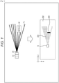
- FIG. 1 A principle of detecting an obstacle 12 by a mobile object 11 including a light detection and ranging or laser imaging detection and ranging (LiDAR) 21 will be first described with reference to Fig. 1 .
- the upper part of Fig. 1 is a diagram of the mobile object 11 viewed from above, and the lower part of Fig. 1 corresponding to the upper part of Fig. 1 illustrates an exemplary occupancy grid map as a local map around the mobile object 11.
- Fig. 1 illustrates that the mobile object 11 moves in a traveling direction which is rightward in the figure, for example, and the obstacle 12 is present ahead of the mobile object 11 in its moving direction and slightly on the right.
- the LiDAR 21 projects a laser light in a respective radial light projection direction L as illustrated in the upper part of Fig. 1 ahead in the moving direction while horizontally rotating a light projection unit arranged at a plurality of angles in the vertical direction, and receives a light reflected on the obstacle 12 thereby to find a distance on the basis of a round-trip time as a difference between the light projection time and the reflected light reception time and to measure a distance and a direction to the obstacle 12.
- An occupancy grid map as a local map as illustrated in the lower part of Fig. 1 is found on the basis of the measurement results by the LiDAR 21.
- the occupancy grid map is generated by dividing a space around the mobile object 11 into a plurality of cells in a grid pattern and classifying each cell into any of with obstacle, free space without obstacle, and unknown region on the basis of the ray tracing principle for the measurement results by the LiDAR 21.
- a range without a distance measurement result by the LiDAR 21 (a range outside the light projection direction) is indicated in white, and a region Z32 indicating unknown is set.
- a gray region Z31 indicating a free space (a range in which an obstacle is less likely to be present) is set by the LiDAR 21 in a range in which reception of a reflected light from the obstacle 12 is not confirmed (a range in the light projection direction but without reception of a reflected light).
- a black region Z33 indicating that the obstacle 12 is highly likely to be present is set by the LiDAR 21 in a range in which a reflected light is received and a distance is measured.
- a laser light is discretely projected in a 2D space in the horizontal direction and the vertical direction which are orthogonal to the light projection direction, and thus if a small obstacle is present between adjacent light projection directions, the obstacle may not be detected.
- a reflected light may not be received, and thus the small obstacle may not be reflected on the occupancy grid map as a local map as illustrated in the lower left of Fig. 2 .
- a projected laser light is not reflected on the obstacle 41, and the fact is indicated in a dotted line in the occupancy grid map in the lower left of Fig. 2 .
- a monocular camera 51 is provided on the mobile object 11 instead of the LiDAR 21 as illustrated in the upper right of Fig. 2 and a distance and a direction of an obstacle are detected on the basis of an image shot by the camera 51.
- the camera 51 can continuously detect the presence and distance of an object, even the small obstacle 41 at pixel level in a 2D space orthogonal to the shooting direction, thereby almost accurately capturing the obstacle 41.
- the occupancy grid map as a local map is to be generated on the basis of an image shot by the camera 51, an accuracy of measuring the distances to the obstacles 12 and 41 is lower than that with the LiDAR 21.
- the probability that an object is present near the obstacles 12 and 41 is diffused and set as indicated by regions Z33' and Z41' in the lower right of Fig. 2 , for example, and thus the presence of the obstacles 12 and 41 can be confirmed but both the directions and the distances thereof are ambiguous.
- the LiDAR 21 is in a discrete range as indicated in the light projection directions L1 to Ln relative to a 2D space orthogonal to a monitoring direction as illustrated on the left of Fig. 3 , and thus a distance can be measured at low spatial resolution but with high accuracy.
- the camera 51 is in a substantially-continuous range at pixel level relative to a 2D space orthogonal to a monitoring direction as indicated by a shooting plane D, and thus spatial resolution is high but distance measurement accuracy is low.
- the camera 51 can capture objects in a substantially-continuous range relative to the entire shooting plane D as illustrated on the right of Fig. 3 , and thus object recognition accuracy is high.
- the LiDAR 21 can detect obstacles just discretely relative to the shooting plane D as indicated in dots, and thus object recognition accuracy of the obstacles is low.
- the LiDAR 21 and the camera 51 are combined to make use of the respective characteristics thereof, thereby enhancing spatial resolution, object recognition accuracy, and distance accuracy and generating a high-definition local map.
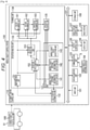
- Fig. 4 is a block diagram illustrating an exemplary configuration of the schematic functions of a mobile object control system 100 for controlling a mobile object 91 according to an embodiment of the present disclosure. Additionally, the mobile object control system 100 in Fig. 4 is an exemplary control system applicable to various mobile objects to which the present technology is applicable, and can be applied as a system for controlling a vehicle, an airplane, a ship, a drone, a robot, and the like, for example.
- the mobile object control system 100 includes an input unit 101, a data acquisition unit 102, a communication unit 103, a mobile object internal device 104, an output control unit 105, an output unit 106, a drive system control unit 107, a drive system 108, a storage unit 109, and an automatic driving control unit 110.
- the input unit 101, the data acquisition unit 102, the communication unit 103, the output control unit 105, the drive system control unit 107, the storage unit 109, and the automatic driving control unit 110 are mutually connected via a communication network 121.
- the communication network 121 is configured of a communication network, a bus, or the like conforming to any standard such as controller area network (CAN), local interconnect network (LIN), local area network (LAN), FlexRay (registered trademark), or the like. Additionally, the respective units in the mobile object control system 100 may be directly connected not via the communication network 121.
- CAN controller area network
- LIN local interconnect network
- LAN local area network
- FlexRay registered trademark
- each unit in the mobile object control system 100 makes communication via the communication network 121
- the description of the communication network 121 will be omitted below.
- the case will be simply described as the input unit 101 and the automatic driving control unit 110 make communication.
- the input unit 101 includes a device used by a passenger for inputting various items of data, instructions, and the like.
- the input unit 101 includes an operation device or the like capable of inputting in a way other than manual operation via an operation device such as touch panel, button, microphone, switch, or lever, audio, gesture, and the like.
- the input unit 101 may be a remote-controlled device using infrared ray or other radio wave, or an externally-connected device such as mobile device or wearable device for the operations of the mobile object control system 100.
- the input unit 101 generates an input signal on the basis of passenger-input data, instruction, or the like, and supplies it to each unit in the mobile object control system 100.
- the data acquisition unit 102 includes various sensors and the like configured to acquire data used for the processing of the mobile object control system 100, and supplies the acquired data to each unit in the mobile object control system 100.
- the data acquisition unit 102 includes various sensors configured to detect a state and the like of the mobile object.
- the data acquisition unit 102 includes a gyro sensor, an acceleration sensor, an inertia measurement unit (IMU), a sensor configured to detect the operation amount of the accelerator pedal, the operation amount of the brake pedal, a steering angle of the steering wheel, engine revolutions, the number of motor rotations, or a rotation speed of wheels, and the like.
- IMU inertia measurement unit
- the data acquisition unit 102 includes various sensors configured to detect external information of the mobile object.
- the data acquisition unit 102 includes a shooting device such as time of flight (ToF) camera, stereo camera, monocular camera, infrared camera, and other camera.
- the data acquisition unit 102 includes an environment sensor configured to detect weather, meteorological phenomenon, or the like, and a surrounding information detection sensor configured to detect an object around the mobile object.
- the environment sensor is configured of a raindrop sensor, a fog sensor, a sunlight sensor, a snow sensor, or the like, for example.
- the surrounding information detection sensor is configured of an ultrasonic sensor, a radar, a light detection and ranging or laser imaging detection and ranging (LiDAR), a sonar, or the like, for example.
- the data acquisition unit 102 includes a camera 302 ( Fig. 5 ) described below as a shooting device, and includes a LiDAR 301 ( Fig. 5 ) as a surrounding information detection sensor.
- the data acquisition unit 102 includes various sensors configured to detect a current position of the mobile object.
- the data acquisition unit 102 includes a GNSS receiver or the like configured to receive a GNSS signal from a global navigation satellite system (GNSS).
- GNSS global navigation satellite system
- the data acquisition unit 102 includes various sensors configured to detect internal information of the mobile object.
- the data acquisition unit 102 includes a shooting device configured to shoot the driver, a biological sensor configured to detect biological information of the driver, a microphone configured to collect voices inside the mobile object, and the like.
- the biological sensor is provided on, for example, a seat, the steering wheel, or the like, and detects biological information of a passenger on the seat or the driver gripping the steering wheel.
- the communication unit 103 makes communication with the mobile object internal device 104, various devices outside the mobile object, a server, a base station, and the like, and transmits data supplied from each unit in the mobile object control system 100 or supplies received data to each unit in the mobile object control system 100. Additionally, a communication protocol supported by the communication unit 103 is not particularly limited, and the communication unit 103 can support a plurality of kinds of communication protocols.
- the communication unit 103 makes wireless communication with the mobile object internal device 104 via wireless LAN, Bluetooth (registered trademark), near field communication (NFC), wireless USB (WUSB), or the like. Further, for example, the communication unit 103 makes wired communication with the mobile object internal device 104 via a connection terminal (not illustrated) (and cable as necessary) by use of universal serial bus (USB), high-definition multimedia interface (HDMI), mobile high-definition link (MHL), or the like.
- USB universal serial bus
- HDMI high-definition multimedia interface
- MHL mobile high-definition link
- the communication unit 103 makes communication with a device (such as application server or control server) present on an external network (such as Internet, Cloud network, or provider-specific network) via a base station or access point. Further, for example, the communication unit 103 makes communication with a terminal (such as pedestrian's or shop's terminal, or machine type communication (MTC) terminal) present near the mobile object by the peer to peer (P2P) technology. Further, for example, in a case where the mobile object 91 is a vehicle, the communication unit 103 makes V2X communication such as vehicle to vehicle communication, vehicle to infrastructure communication, vehicle to home communication, and vehicle to pedestrian communication. Further, for example, the communication unit 103 includes a beacon reception unit, and receives a radio wave or electromagnetic wave originated from a wireless station or the like installed on the road thereby to acquire information such as current position, traffic jam, traffic rule, or necessary time.
- a device such as application server or control server
- an external network such as Internet, Cloud network, or provider-specific network
- MTC machine type communication
- the mobile object internal device 104 includes a mobile device or wearable device owned by a passenger, an information device mounted or attached on the mobile object, a navigation device configured to search a route to any destination, and the like, for example.
- the output control unit 105 controls outputting various items of information to a passenger of the mobile object or the outside of the mobile object.
- the output control unit 105 generates an output signal including at least one of visual information (such as image data) and auditory information (such as audio data) and supplies it to the output unit 106 thereby to control outputting the visual information and the auditory information from the output unit 106.
- the output control unit 105 combines image data shot by a different shooting device in the data acquisition unit 102, generates a perspective image, panorama image, or the like, and supplies an output signal including the generated image to the output unit 106.
- the output control unit 105 generates audio data including an alarm sound or alarm message against danger such as collision, contact, entry into danger zone, and the like, and supplies an output signal including the generated audio data to the output unit 106.
- the output unit 106 includes a device capable of outputting visual information or auditory information to a passenger of the mobile object or the outside of the mobile object.
- the output unit 106 includes a display device, an instrument panel, an audio speaker, a headphone, a wearable device such as glasses-type display put on a passenger, a projector, a lamp, and the like.
- the display device provided in the output unit 106 may be, for example, a device configured to display visual information within a field of view of the driver such as a headup display, a transmissive display, or a device having an augmented reality (AR) display function in addition to a device having a normal display.
- AR augmented reality
- the drive system control unit 107 generates various control signals and supplies them to the drive system 108 thereby to control the drive system 108. Further, the drive system control unit 107 supplies the control signals to each unit other than the drive system 108 as necessary, notifies a control state of the drive system 108, and the like.
- the drive system 108 includes various devices for the drive system of the mobile object.
- the drive system 108 includes a drive force generator configured to generate a drive force such as internal engine or drive motor, a drive force transmission mechanism configured to transmit a drive force to the wheels, a steering mechanism configured to adjust a steering angle, a braking device configured to generate a braking force, an antilock brake system (ABS), an electronic stability control (ESC), a power-assisted power steering device, and the like, for example.
- a drive force generator configured to generate a drive force such as internal engine or drive motor
- a drive force transmission mechanism configured to transmit a drive force to the wheels
- a steering mechanism configured to adjust a steering angle
- a braking device configured to generate a braking force
- ABS antilock brake system
- ESC electronic stability control
- a power-assisted power steering device and the like, for example.
- the storage unit 109 includes, for example, a magnetic storage device such as read only memory (ROM), random access memory (RAM), or hard disc drive (HDD), a semiconductor storage device, an optical storage device, a magnetooptical storage device, and the like.
- the storage unit 109 stores various programs or data used in each unit of the mobile object control system 100.
- the storage unit 109 stores map data such as a high-definition map such as dynamic map, a global map which is less accurate than high-definition map and is directed for covering a wider area, a local map including information around the mobile object, and the like.
- the automatic driving control unit 110 controls automatic driving such as autonomous movement or driving assistance. Specifically, for example, the automatic driving control unit 110 conducts cooperative control for realizing the functions of an advanced driver assistance system (ADAS) including such as collision avoidance or impact relaxation of the mobile object, follow-up movement based on inter-mobile object distance, movement with mobile object speed kept, collision alarm of the mobile object, or lane deviation alarm of the mobile object. Further, for example, the automatic driving control unit 110 conducts cooperative control for automatic driving such as autonomous movement irrespective of driver's operation.
- the automatic driving control unit 110 includes a detection unit 131, a self-position estimation unit 132, a situation analysis unit 133, a planning unit 134, and an operation control unit 135.
- the detection unit 131 detects various items of information necessary for controlling automatic driving.
- the detection unit 131 includes a mobile object external information detection unit 141, a mobile object internal information detection unit 142, and a mobile object state detection unit 143.
- the mobile object external information detection unit 141 performs a processing of detecting external information of the mobile object on the basis of data or a signal from each unit in the mobile object control system 100.
- the mobile object external information detection unit 141 performs a processing of detecting an object around the mobile object, a recognition processing, and a tracking processing as well as a processing of detecting a distance to an object.
- the objects to be detected include other mobile object, person, obstacle, structure, road, traffic light, traffic sign, road sign, and the like, for example.
- the mobile object external information detection unit 141 performs a processing of detecting an environment around the mobile object.
- the surrounding environments to be detected include weather, temperature, humidity, brightness, road state, and the like, for example.
- the mobile object external information detection unit 141 supplies the data indicating the results of the detection processing to the self-position estimation unit 132, a map analysis unit 151 and a situation recognition unit 152 in the situation analysis unit 133, an emergency avoidance unit 171 in the operation control unit 135, and the like.
- the mobile object internal information detection unit 142 performs a processing of detecting internal information of the mobile object on the basis of data or a signal from each unit in the mobile object control system 100.
- the mobile object internal information detection unit 142 performs the processing of authenticating and recognizing the driver, a processing of detecting a state of the driver, a processing of detecting a passenger, a processing of detecting an environment inside the mobile object, and the like.
- the states of the driver to be detected include physical condition, degree of wakefulness, degree of concentration, degree of fatigue, eye direction, and the like, for example.
- the environments inside the mobile object to be detected include temperature, humidity, brightness, odor, and the like, for example.
- the mobile object internal information detection unit 142 supplies the data indicating the results of the detection processing to the situation recognition unit 152 in the situation analysis unit 133, the emergency avoidance unit 171 in the operation control unit 135, and the like.
- the mobile object state detection unit 143 performs a processing of detecting a state of the mobile object on the basis of data or a signal from each unit in the mobile object control system 100.
- the states of the mobile object to be detected include speed, acceleration, steering angle, presence and contents of abnormality, driving operation state, position and tilt of power sheet, door lock state, state of other mobile object-mounted device, and the like, for example.
- the mobile object state detection unit 143 supplies the data indicating the results of the detection processing to the situation recognition unit 152 in the situation analysis unit 133, the emergency avoidance unit 171 in the operation control unit 135, and the like.
- the self-position estimation unit 132 performs a processing of estimating a position, a posture, and the like of the mobile object on the basis of data or a signal from each unit in the mobile object control system 100 such as the mobile object external information detection unit 141 and the situation recognition unit 152 in the situation analysis unit 133. Further, the self-position estimation unit 132 generates a local map used for estimating a self-position (which will be denoted as self-position estimation map below) as necessary.
- the self-position estimation map is assumed as a high-definition map using a technology such as simultaneous localization and mapping (SLAM), for example.
- SLAM simultaneous localization and mapping
- the self-position estimation unit 132 supplies the data indicating the result of the estimation processing to the map analysis unit 151 and the situation recognition unit 152 in the situation analysis unit 133, and the like. Further, the self-position estimation unit 132 stores a self-position estimation map in the storage unit 109.
- the situation analysis unit 133 performs a processing of analyzing the situations of the mobile object and its surroundings.
- the situation analysis unit 133 includes the map analysis unit 151, the situation recognition unit 152, and a situation prediction unit 153.
- the map analysis unit 151 performs a processing of analyzing various maps stored in the storage unit 109 by use of data or a signal from each unit in the mobile object control system 100 such as the self-position estimation unit 132 and the mobile object external information detection unit 141 as necessary, and constructs a map including information necessary for the automatic driving processing.
- the map analysis unit 151 supplies the constructed map to the situation recognition unit 152 and the situation prediction unit 153 as well as a route planning unit 161, an action planning unit 162, an operation planning unit 163 in the planning unit 134, and the like.
- the situation recognition unit 152 performs a processing of recognizing a situation of the mobile object on the basis of data or a signal from each unit in the mobile object control system 100 such as the self-position estimation unit 132, the mobile object external information detection unit 141, the mobile object internal information detection unit 142, the mobile object state detection unit 143, and the map analysis unit 151.
- the situation recognition unit 152 performs a processing of recognizing a situation of the mobile object, a situation around the mobile object, a situation of the driver of the mobile object, and the like.
- the situation recognition unit 152 generates a local map used for recognizing a situation around the mobile object (which will be denoted as situation recognition map below) as necessary.
- the situation recognition map is assumed as an occupancy grid map, for example.
- the situations of the mobile object to be recognized include position, posture, and motion (such as speed, acceleration, and moving direction) of the mobile object as well as presence, contents, and the like of an abnormality, for example.
- the situations around the mobile object to be recognized include kind and position of a surrounding still object, kind, position, and motion of a surrounding moving object (such as speed, acceleration, and moving direction), structure of surrounding road, and state of the road, as well as surrounding weather, temperature, humidity, brightness, and the like.
- the states of the driver to be recognized include physical condition, degree of wakefulness, degree of concentration, degree of fatigue, motion of line of sight, driving operation, and the like, for example.
- the situation recognition unit 152 supplies the data (including a situation recognition map as necessary) indicating the results of the recognition processing to the self-position estimation unit 132, the situation prediction unit 153, and the like. Further, the situation recognition unit 152 stores the situation recognition map in the storage unit 109.
- the situation prediction unit 153 performs a processing of predicting a situation of the mobile object on the basis of data or a signal from each unit in the mobile object control system 100 such as the map analysis unit 151 and the situation recognition unit 152. For example, the situation prediction unit 153 performs a processing of predicting a situation of the mobile object, a situation around the mobile object, a situation of the driver, and the like.
- the situations of the mobile object to be predicted include behavior of the mobile object, occurrence of abnormality, movable distance, and the like, for example.
- the situations around the mobile object to be predicted include behavior of a moving object around the mobile object, change in signal state, change in environment such as weather, and the like, for example.
- the situations of the driver to be predicted include behavior, physical condition, and the like of the driver, for example.
- the situation prediction unit 153 supplies the data indicating the results of the prediction processing to the route planning unit 161, the action planning unit 162, the operation planning unit 163 in the planning unit 134 together with the data from the situation recognition unit 152, and the like.
- the route planning unit 161 plans a route to a destination on the basis of data or a signal from each unit in the mobile object control system 100 such as the map analysis unit 151 and the situation prediction unit 153. For example, the route planning unit 161 sets a route from a current position to a designated destination on the basis of the global map. Further, for example, the route planning unit 161 changes the route as necessary on the basis of situations of traffic jam, accident, traffic regulation, construction, and the like and physical condition of driver. The route planning unit 161 supplies the data indicating the planned route to the action planning unit 162 and the like.
- the action planning unit 162 plans an action of the mobile object in order to safely move along the route planned by the route planning unit 161 within the planned time on the basis of data or a signal from each unit in the mobile object control system 100 such as the map analysis unit 151 and the situation prediction unit 153. For example, the action planning unit 162 plans start, stop, traveling direction (such as forward travel, backward travel, left turn, right turn, and change in direction), moving speed, overtaking, and the like. The action planning unit 162 supplies the data indicating the planned action of the mobile object to the operation planning unit 163 and the like.
- the operation planning unit 163 plans an operation of the mobile object in order to realize an action planned by the action planning unit 162 on the basis of data or a signal from each unit in the mobile object control system 100 such as the map analysis unit 151 and the situation prediction unit 153. For example, the operation planning unit 163 plans acceleration, deceleration, moving trajectory, and the like. The operation planning unit 163 supplies the data indicating the planned operation of the mobile object to the operation control unit 135 and the like.
- the operation control unit 135 controls the operations of the mobile object.
- the operation control unit 135 performs a processing of detecting emergency situations such as collision, contact, entry into danger zone, abnormality of the driver, and abnormality of the mobile object on the basis of the detection results of the mobile object external information detection unit 141, the mobile object internal information detection unit 142, and the mobile object state detection unit 143.
- the operation control unit 135 detects an occurrence of an emergency, it plans an operation of the mobile object in order to avoid the emergency such as sudden stop or steep turn.
- the operation control unit 135 controls acceleration/deceleration in order to realize an operation of the mobile object planned by the operation planning unit 163. For example, the operation control unit 135 calculates a control target value of the drive force generator or the braking device for realizing planned acceleration, deceleration, or sudden stop, and supplies a control command indicating the calculated control target value to the drive system control unit 107.
- the operation control unit 135 conducts direction control in order to realize an operation of the mobile object planned by the operation planning unit 163. For example, the operation control unit 135 calculates a control target value of the steering mechanism in order to realize moving trajectory or steep turn planned by the operation planning unit 163, and supplies a control command indicating the calculated control target value to the drive system control unit 107.
- an environment map described herein is a local map used for recognizing a situation around the mobile object described above, or a situation recognition map, and more specifically an occupancy grid map.
- the detailed exemplary configuration of environment map generation is configured of the data acquisition unit 102, the mobile object external information detection unit 141 in the detection unit 131 in the automatic driving control unit 110, and the situation recognition unit 152 in the situation analysis unit 133 as illustrated in Fig. 5 .
- the data acquisition unit 102 includes the LiDAR 301 and the camera 302.
- the mobile object external information detection unit 141 includes a camera image superimposition unit 311 and a semantic segmentation unit 312.
- the situation recognition unit 152 includes an adaptive environment mapping unit 321 and a temporal integration unit 322.
- the LiDAR 301 projects a laser light in a respective radial light projection direction L ahead in the moving direction of the mobile object 91 as illustrated in the upper part of Fig. 1 while horizontally rotating the light projection unit arranged at a plurality of angles in the vertical direction, and receives a light reflected on the obstacle 12 thereby to find a distance on the basis of a round-trip time as a difference between the light projection time and the reflected light reception time and to measure a distance and a direction to the obstacle 12.
- the LiDAR 301 measures a distance from the mobile object 91 to the obstacle in each light projection direction in the so-called time of flight (ToF) method, and outputs the measurement result including a group of 3D points to the camera image superimposition unit 311.
- ToF time of flight
- the LiDAR 301 may be configured such that light projection units and light reception units are provided in a 2D array to acquire 2D distance measurement information, and may be configured such that one light projection unit and one light reception unit two-dimensionally scans.
- any device which can measure 2D distance measurement information capable of acquiring a group of 3D points, can be employed other than the LiDAR 301, and a ToF camera and the like can be employed, for example.
- the camera 302 is configured of a shooting device such as complementary metal oxide semiconductor (CMOS), shoots in front of the mobile object 91 and makes image correction such as demosaic processing or distortion correction based on a pre-calibration result, and then outputs the corrected RGB image to the semantic segmentation unit 312.
- CMOS complementary metal oxide semiconductor
- the camera image superimposition unit 311 converts the distance measurement result of the LiDAR 301 from the coordinate system information of the LiDAR 301 to the coordinate system information of the camera 302 to be a distance image corresponding to the image shot by the camera 302, and outputs the distance image to the semantic segmentation unit 312 and the adaptive environment mapping unit 321.
- the semantic segmentation unit 312 classifies the types of subjects in units of pixel by semantic segmentation on the basis of the RGB image shot by the camera 302 and the distance image, gives a semantic label corresponding to a classification result to them, and outputs them to the adaptive environment mapping unit 321 and the temporal integration unit 322. Additionally, both an RGB image and a distance image are not necessary for semantic segmentation, and semantic segmentation may be performed by only an RGB image or may be performed by only a distance image. Further, not an RGB image but a monochrome image may be employed, for example. However, semantic segmentation using both an RGB image (or monochrome image) and a distance image is more accurate.
- the adaptive environment mapping unit 321 generates an environment map at a current time by the environment adaptive mapping processing on the basis of the distance image and the semantic labels given in units of pixel, and outputs the generated environment map to the temporal integration unit 322.
- the temporal integration unit 322 accumulates and integrates the environment maps which are sequentially generated in time series and supplied by the adaptive environment mapping unit 321 thereby to configure a global map, and outputs the global map as a final environment map.
- a measurement result of the LiDAR 301 is information indicating a group of points in a 3D space, and the measurement result is superimposed on an image shot by the camera 302 thereby to generate a distance image.
- a measurement result in each light projection direction Lp of the LiDAR 301 is superimposed on an image P11 by the camera 302 illustrated in the upper left of Fig. 6 thereby to generate a distance image.
- the camera image superimposition unit 311 acquires, as prior information, the information indicating the relative positions of the LiDAR 301 and the camera 302 as well as the center of the image and the focal distance of the camera 302, thereby generating a distance image by the following calculations using the prior information.
- the camera image superimposition unit 311 integrates the coordinate system of the LiDAR 301 with the coordinate system of the camera 302.
- X cam RX LiDAR + T
- R indicates a rotation matrix indicating rotation previously known by calibration between the LiDAR 301 and the camera 302
- T indicates a translation vector also previously known by calibration.
- Equation (1) is calculated so that the coordinate of the point X in the measurement result measured as coordinate system information of the LiDAR 301 is converted into the camera coordinate system.
- the camera image superimposition unit 311 then associates the distance measurement result of the LiDAR 301 with the coordinate system on the shooting plane of the camera 302.
- the coordinate xi in the image plane can be found as in the following Equation (2) with reference to the image center Pc of the shooting plane D of the obstacle in the shooting plane D as illustrated in the lower right of Fig. 6 .
- xi f ⁇ xc / zc where f is a focal distance of the camera 302.
- the position of the obstacle on the shooting plane D can be specified.
- the camera image superimposition unit 311 generates a distance image P12 as illustrated in the lower left of Fig. 6 in the processing.
- the distance image P12 is assumed to be arranged at the same pixels as the image of the camera 302, where the pixels, which are in the light projection direction of the LiDAR 301 and have a distance measurement result due to the coordinate system conversion, among the pixels (xi, yi) are associated and their distance data (zc in the lower right of Fig. 6 ) is stored, and the pixels, which are not in the light projection direction and do not have a distance measurement result, are stored with distance data of 0, for example.
- Semantic segmentation by the semantic segmentation unit 312 will be described below with reference to Fig. 7 .
- the camera 302 shoots an image P31 including an RGB image at an angle of view Z1 in which a road 341 is present in a space horizontally sandwiched by still structures 342-1 and 342-2, a person 344 is present on the road 341, and sky 343 is present in the back as illustrated on the left of Fig. 7 .
- the semantic segmentation unit 312 classifies and labels the kinds of the subjects in the image P31 in units of pixels by machine learning such as deep learning on the basis of the image P31 including an RGB image and a distance image P32 as illustrated in the upper middle of Fig. 7 .
- classification and labeling are performed by semantic segmentation as illustrated in a labeling image P41 in the lower right of Fig. 7 , for example.
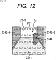
- the pixels belonging to a region Z341 at the bottom of the image are classified as the road 341
- the pixels belonging to regions Z342-1 and Z342-2 are classified as the horizontal still structures 342-1 and 342-2, respectively
- the pixels belonging to a region Z343 is classified as the sky 343 above in the back
- the pixels belonging to a region Z344 are classified as the person 344.
- the semantic segmentation unit 312 identifies and labels, for example, roads, still structures (such as wall, guardrail, tree, and telephone pole), vehicles (such as automobile, truck and bus), two wheels (such as bike and bicycle), persons, horizontal bars (such as railroad crossing, ETC bar, and parking gate bar), and the sky in an RGB image, in units of pixels other than the examples of Fig. 7 on the basis of an RGB image and a distance image.
- semantic segmentation is possible for classifying subjects through machine learning by only an RGB image or by only a distance image, but is less accurate than in combination of an RGB image and a distance image.
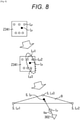
- Adaptive environment mapping by the adaptive environment mapping unit 321 will be described below with reference to Fig. 8 .
- the adaptive environment mapping unit 321 adaptively generates an environment map on the basis of the distance image, and the semantic labels classified per subject by semantic segmentation.
- the adaptive environment mapping unit 321 can generate an environment map by use of the information.
- the adaptive environment mapping unit 321 interpolates and generates distance information and generates a higher-definition distance image for each pixel of the RGB image.
- the adaptive environment mapping unit 321 interpolates and generates distance information for pixels without distance information by use of known distance information for each pixel in a region classified with a semantic label of road.
- the adaptive environment mapping unit 321 reads the coordinates S(Lp1) to S(Lp3) in the 3D space of the pixels Lp1 to Lp3 having distance information nearest to the pixel Ip as illustrated in the range surrounded in a dotted line in the middle of Fig. 8 .
- a plane can be specified by three known points, and the adaptive environment mapping unit 321 finds a plane S configuring the road 341 defined in the following Equation (4) on the basis of the information indicating the coordinates S(Lp1) to S(Lp3) in the 3D space of the pixels Lp1 to Lp3 as illustrated in the lower part of Fig. 8 .
- the adaptive environment mapping unit 321 finds the coordinate S(Ip) corresponding to the pixel Ip on the plane S configuring the road 341 on the basis of an eye vector Ve from the camera 302 to the pixel Ip as illustrated in Fig. 9 .
- s indicates a coefficient or the scalar amount.
- xi and yi indicate the coordinates of the pixel Ip on the shooting plane with the image center of the shooting plane D as origin, and f indicates a focal distance. That is, a vector to the intersection point S(Ip) with the camera 302 as start point is a multiple of the coefficient s of the eye vector Ve.
- the Equation (5) is substituted in the Equation of the plane S configuring the road, which is defined in the Equation (4), thereby to find a constant s, and the constant s is found thereby to find the coordinate of the intersection point S(Ip) on the plane S.
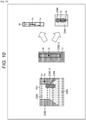
- the adaptive environment mapping unit 321 interpolates and generates distance information for pixels without distance information by use of known distance information among the pixels in a region classified with a semantic label of obstacle such as still structure or person.
- the adaptive environment mapping unit 321 reads the coordinates in the 3D space of the pixels with known distance information indicated in white dots in the range surrounded by a vertically-long frame W around the pixel Ip as illustrated in the middle of Fig. 10 .
- the frame W is set in a vertically-long range around the pixel Ip indicated in a black dot for which distance information is interpolated and generated since many subjects are likely to have the same distance information in the vertical direction in the region with the same label.
- the adaptive environment mapping unit 321 reads the information indicating the coordinates in the 3D space of the known pixels, and interpolates and generates the coordinate in the 3D space of the pixel Ip by use of the read information as illustrated in the upper right of Fig. 10 .
- the adaptive environment mapping unit 321 interpolates and generates the coordinate in the 3D space of the pixel Ip by a weighted linear sum depending on the position relationship from the pixel Ip by use of the information indicating the coordinates in the 3D space of the known pixels.
- the adaptive environment mapping unit 321 determines whether the obstacle contacts with the region Z341 classified as the road 341 vertically below the region with the same label.
- the distance information can be assumed as the same as the distance information on the road 341 contacted vertically below the region with the same label.
- the adaptive environment mapping unit 321 sets the same distance information as the distance information at the coordinate on the corresponding road 341 for the distance information of the pixel Ip. Additionally, the distance information of the road 341 makes use of the distance information of the road 341 found in the above method.
- the adaptive environment mapping unit 321 sets 0 indicating unknown for the distance information of the pixel Ip.
- the adaptive environment mapping unit 321 interpolates and generates distance information for pixels without distance information by use of known distance information among the pixels in a region classified with a semantic label of horizontal bar used for entrance/exit gate or the like.
- the resolution is low in the LiDAR 301 or the like, and less pixels have distance information found.
- the adaptive environment mapping unit 321 uses the information indicating the pixels with distance information near the pixel Ip for which distance information is to be interpolated and generated in the region with the same label.
- the adaptive environment mapping unit 321 uses, as the distance information of the pixel Ip, the average value of the distance information of the pixels Lp1 to Lp4 with known distance information indicated in white dots, or the distance information of the nearest pixel Lp1 in the region Z361.
- the adaptive environment mapping unit 321 interpolates and generates distance information of each pixel in a region classified with a semantic label of sky.
- a distance may not be measured in many cases due to infinite distance, and if the distance is measured, noises due to sunlight or the like are caused in many cases in the region Z343 classified as the sky 343, and thus the adaptive environment mapping unit 321 gives the interpolation result of 0 indicating unknown to the distance information of the pixel Ip without distance information.
- distance information is given to each pixel of an image shot by the camera 302 so that the adaptive environment mapping unit 321 generates an environment map.
- the adaptive environment mapping unit 321 sets a grid pattern on the plane (XZ plane) with horizontal direction and depth, and determines the presence of an obstacle per cell configured in the grid pattern on the basis of the distance information of each pixel, thereby completing an occupancy grid map.
- information indicating a distance and a direction in which a light projected by the LiDAR 301 is regarded as reflected on an obstacle is distance information in units of pixel, and thus a cell, in which an obstacle should be regarded as present in association with distance information, is present in each pixel if the distance information indicates road or is not 0 indicating unknown.
- an obstacle such as still structure or person is likely to be present due to distance information in a cell in which an obstacle is regarded as present by many pixels.
- the adaptive environment mapping unit 321 specifies, for each cell, a cell in which the number of pixels which are regarded as obstacle on the basis of distance information is higher than the predetermined number as a cell in which an obstacle is likely to be present.
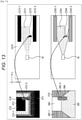
- the black regions Z372-1, Z372-2, and Z373 are the regions of obstacles in the upper right of Fig. 13 . Further, the regions Z372-1, Z372-2, and Z373 correspond to the still structures 372-1, 372-2, and a person 373 in a distance image P71 generated on the basis of the interpolated and generated distance information in the upper left of Fig. 13 , respectively.
- a region Z371 indicating that an obstacle is not present is set in the range between the mobile object 91 and the regions Z372-1, Z372-2, and Z373 of the obstacles, and a region Z374 indicating unknown due to the absence of a distance measurement result is set in the range beyond the range in which the region Z373 is set.
- the adaptive environment mapping unit 321 generates a label map on the basis of the distance information and the semantic label information of each pixel of the image shot by the camera 302.
- the adaptive environment mapping unit 321 specifies, for each cell, a label for which the number of pixels with the same label is the highest as a label of the cell.
- the region Z341 in the lower right of Fig. 13 corresponds to the road 341 in a label image P72 configured of a semantic label in the lower left of Fig. 13 .
- the regions Z342-1 and Z342-2 in the lower right of Fig. 13 correspond to the still structures 372-1 and 372-2 in the lower left of Fig. 13 , respectively.
- the region Z344 in the lower right of Fig. 13 corresponds to the person 344 in the lower left of Fig. 13 .
- the adaptive environment mapping unit 321 generates environment maps in real-time and sequentially in time series, and the temporal integration unit 322 integrates the environment maps generated in time series in the temporal direction thereby to generate a global map, and outputs the global map as a final environment map.
- a global map is a map M2 configured by overlapping a plurality of environment maps M1 illustrated on the left of Fig. 14 on an environment map M1 generated in time series illustrated on the right of Fig. 14 .
- the global map M2 is configured by overlapping in time series an environment map V1-1 generated on the basis of an image shot by a camera 302-1 at time t1, an environment map V1-2 generated on the basis of an image shot by a camera 302-2 at time t2, and an environment map V1-3 generated on the basis of an image shot by a camera 302-3 at time t3.
- the environment maps V1-1 to V1-3 draw only the traced V1 indicating the angle of view of the environment map M1 on the right of Fig. 14 in time series, and is not an actual environment map.
- the environment map M1 on the right of Fig. 14 corresponds to the environment map V1-3 on the left of Fig. 14 .
- the environment maps are attached and accumulated in time series in this way so that the global map M2 is sequentially expanded.
- the global map M2 is sequentially expanded.
- Fig. 15 illustrates an exemplary configuration of the temporal integration unit 322.
- the temporal integration unit 322 includes global coordinate conversion units 401, 402, a temporal integration processing unit 403, a buffer 404, and a moving object arrangement unit 405.
- the global coordinate conversion unit 401 converts a subject labeled as a moving object into a global coordinate as a global map coordinate system on the basis of self-position information, and outputs the global coordinate to the temporal integration processing unit 403 and the moving object arrangement unit 405. Additionally, if the first reference self-position is known, a self-position may be the amount of sequential change from a previous self-position.
- the global coordinate conversion unit 402 converts an environment map into the global coordinate as a global map coordinate system on the basis of the self-position information, and outputs the global coordinate to the temporal integration processing unit 403. Additionally, if the first reference self-position is known, a self-position may be the amount of sequential change from a previous self-position.
- the temporal integration processing unit 403 excludes a cell of a moving object from the environment map converted into the global map coordinate system, and adds and accumulate it on the global map stored in the buffer 404 on the basis of the information indicating the moving object converted into the global map coordinate system, and stores the global map in the buffer 404 and outputs it to the moving object arrangement unit 405.
- the temporal integration processing unit 403 repeatedly performs the processing of adding and accumulating an environment map supplied in time series in the global map in consideration of a self-position, thereby integrating the environment maps.
- the method for integrating an environment map into a global map in the temporal integration processing unit 403 may employ the Bayes logic, the Dempster Shafer logic, the Kalman filter, and the like.
- the cell 391 including a moving object is included at time t-1 as illustrated in an environment map M21 on the left of Fig. 16 , for example. Then, at a next time t, the subject corresponding to the cell 391 of the moving object is assumed to move to a cell 392 as illustrated in an environment map M22 in the middle of Fig. 16 .
- the temporal integration processing unit 403 excludes a moving object, and accumulates an environment map including only the motion-less cells except the moving object in the global map.
- the moving object arrangement unit 405 adds an environment map at a current time to the global map supplied by the temporal integration processing unit 403 on the basis of the moving object label, and outputs the global map. With the processing, only the latest cell of the moving object is reflected on the global map.
- step S11 the LiDAR 301 horizontally projects a laser light in a respective radial light projection direction ahead in the moving direction while horizontally rotating the light projection unit arranged at a plurality of angles in the vertical direction, receives a light reflected on an obstacle, finds a distance on the basis of a round-trip time as a difference between the light projection time and the reflected light reception time, and outputs the distance as information indicating a group of 3D points to the camera image superimposition unit 311.
- step S12 the camera image superimposition unit 311 generates a distance image on the basis of the information indicating a group of 3D points in the method described in Fig. 6 , and outputs the generated distance image to the adaptive environment mapping unit 321 and the semantic segmentation unit 312.
- step S13 the camera 302 shoots an RGB image ahead in the moving direction, and outputs it to the semantic segmentation unit 312.
- step S14 the semantic segmentation unit 312 gives a classification result of a subject as a semantic label in units of pixel by semantic segmentation on the basis of the RGB image and the distance image in the method described in Fig. 7 , and outputs it to the adaptive environment mapping unit 321 and the temporal integration unit 322.
- step S15 the adaptive environment mapping unit 321 performs the adaptive environment mapping processing, generates an environment map at a current time on the basis of the distance image and the semantic labels, and outputs the generated environment map to the temporal integration unit 322. Additionally, the adaptive environment mapping processing will be described below with reference to a flowchart of Fig. 18 .
- step S16 the temporal integration unit 322 performs the temporal integration processing, sequentially accumulates the environment maps on the basis of an environment map at a current time and a semantic label thereby to generate a global map, and outputs an environment map as a global map. Additionally, the temporal integration processing will be described below with reference to a flowchart of Fig. 19 .
- step S17 a determination is made as to whether ending is instructed, and in a case where ending is not instructed, the processing returns to step S11 and its subsequent processing are repeatedly performed. Then in step S17, in a case where ending is instructed, the processing ends.
- the pixels for which distance information is not found by the LiDAR 301 among the pixels in the RGB image can be interpolated and generated on the basis of the distance information found by the LiDAR 301 from the information indicating a group of 3D points generated by the LiDAR 301 and the RGB image shot by the camera 302, thereby generating a distance image including the distance information of all the pixels.
- the high-definition distance information can be given, thereby generating a high-definition environment map.
- the environment maps in time series are sequentially accumulated thereby to generate a global map, and thus a self-position and its surrounding situation can be recognized in detail.
- step S31 the adaptive environment mapping unit 321 extracts an RGB image and a distance image in a region labeled as road on the basis of the semantic label information.
- step S32 the adaptive environment mapping unit 321 interpolates and generates the pixels not given distance information among the pixels in the region labeled as road by use of the information of the pixels with distance information as described in Fig. 8 and Fig. 9 .
- step S33 the adaptive environment mapping unit 321 sets an unprocessed label among the labels of other than road as a current label.
- step S34 the adaptive environment mapping unit 321 determines whether a pixel including effective distance information is present in the region with a current label. That is, as described in the middle of Fig. 10 , in a case where the pixels with distance information as indicated in white dots are present in the frame W set for the pixel Ip indicated in a black dot for which distance information is to be found, or in a case where a pixel including distance information is present in the region with the same label as horizontal bar described in Fig. 11 , a pixel including distance information is regarded as present, and the processing proceeds to step S35.
- step S35 the adaptive environment mapping unit 321 interpolates and generates distance information for each pixel without distance information in the region with a current label on the basis of the distance information of the near pixels including the distance information in the current label.
- step S34 in a case where it is regarded that a pixel including distance information is not present in the region with a current label, the processing in the adaptive environment mapping unit 321 proceeds to step S36.
- a semantic label indicates sky or the like as described in Fig. 12
- step S36 the adaptive environment mapping unit 321 determines whether the part vertically below the region with a current label contacts with the road.
- step S36 for example, in a case where the part vertically below the region Z344 of the person 344 contacts with the region Z341 of the road 341 at the boundary Cp as illustrated in the lower right of Fig. 10 , the part vertically below the region with a current label is regarded as contacting with the road, and the processing proceeds to step S37.
- step S37 the adaptive environment mapping unit 321 adds the distance information of the contacted road to the pixels in the region with a current label.
- step S36 in a case where the part vertically below the region with a current label is regarded as not contacting with the road, the processing proceeds to step S38.
- step S38 the adaptive environment mapping unit 321 sets the pixels in the region with a current label at 0 indicating unknown distance information. That is, the adaptive environment mapping unit 321 sets the region with a label of sky or the like at 0 indicating unknown as described in Fig. 12 .
- step S39 the adaptive environment mapping unit 321 determines whether an unprocessed label is present, and in a case where an unprocessed label is present, the processing returns to step S33. That is, the processing in steps S33 to S39 are repeatedly performed until no unprocessed label is present.
- step S39 in a case where the processing ends for all the labels and an unprocessed label is regarded as absent, the processing proceeds to step S40.
- step S40 the adaptive environment mapping unit 321 generates an occupancy grid map and a label map as environment maps for all the pixels corresponding to the RGB image on the basis of the information of the distance image having distance information found and the semantic labels as described in Fig. 13 , outputs them to the temporal integration unit 322, and terminates the processing.
- step S51 the global coordinate conversion unit 401 in the temporal integration unit 322 converts the coordinate in an environment map of a cell with a label regarded as moving object into the global coordinate on the basis of the semantic label information, and outputs it to the temporal integration processing unit 403 and the moving object arrangement unit 405.
- step S52 the global coordinate conversion unit 402 converts the coordinates in the environment map into the global coordinates, and outputs the global coordinates to the temporal integration processing unit 403.
- step S53 the temporal integration processing unit 403 excludes the cell of the moving object from the environment map converted into the coordinate system of the global map, adds it onto the global map stored in the buffer 404 on the basis of the information of the moving object converted into the coordinate system of the global map, accumulates and stores the same regions to be overlapped in the buffer 404 again, and outputs the global map to the moving object arrangement unit 405.
- step S54 the moving object arrangement unit 405 adds an environment map at a current time to the global map supplied from the temporal integration processing unit 403 on the basis of the moving object label, and outputs the global map. That is, only the cell indicating the moving object included in an environment map at a current time can be reflected on the global map.
- the environment maps generated in time series can be accumulated, and a global map capable of easily recognizing a self-position or its surrounding situation can be generated and output as a final environment map.
- the weakness of spatial resolution at which the LiDAR 301 is not good is compensated for by making use of spatial resolution and image recognition accuracy at which the camera 302 is good, and distance accuracy at which the camera 302 is not good is compensated for by the LiDAR 301, thereby generating a high-definition distance image and generating a high-definition environment map.
- the above processing can be performed in hardware, and can be performed in software.
- a computer incorporated in dedicated hardware or various programs are installed so that programs configuring the software can be installed from a recording medium into a general-purpose computer capable of performing various functions, for example.
- Fig. 20 illustrates an exemplary configuration of a general-purpose computer.
- the computer incorporates a central processing unit (CPU) 1001.
- the CPU 1001 is connected with an input/output interface 1005 via a bus 1004.
- the bus 1004 is connected with a read only memory (ROM) 1002 and a random access memory (RAM) 1003.
- ROM read only memory
- RAM random access memory
- the input/output interface 1005 is connected with an input unit 1006 configured of an input device such as keyboard or mouse used by a user for inputting operation commands, an output unit 1007 for outputting a processing operation screen or a processing result image onto a display device, a storage unit 1008 configured of, for example, a hard disc drive for storing programs or various items of data, and a communication unit 1009 configured of a local area network (LAN) adaptor or the like for performing the communication processing via a network such as Internet.
- LAN local area network
- a drive 1010 for writing and reading into and from a removable medium 1011 such as magnetic disc (including flexible disc), optical disc (including compact disc-read only memory (CD-ROM) and digital versatile disc (DVD)), magnetooptical disc (including mini disc (MD)), or semiconductor memory.
- a removable medium 1011 such as magnetic disc (including flexible disc), optical disc (including compact disc-read only memory (CD-ROM) and digital versatile disc (DVD)), magnetooptical disc (including mini disc (MD)), or semiconductor memory.
- the CPU 1001 performs various processing according to the programs stored in the ROM 1002, or the programs read from the removable medium 1011 such as magnetic disc, optical disc, magnetooptical disc or semiconductor memory, installed in the storage unit 1008, and loaded from the storage unit 1008 to the RAM 1003.
- the RAM 1003 stores the data or the like necessary for the CPU 1001 for performing various processing as necessary.
- the CPU 1001 loads and executes the programs stored in the storage unit 1008 into the RAM 1003 via the input/output interface 1005 and the bus 1004, for example, so that the above processing are performed.
- the programs executed by the computer can be recorded and provided in the removable medium 1011 as package medium or the like, for example. Further, the programs can be provided via a wired or wireless transmission medium such as local area network, Internet, or digital satellite broadcasting.
- the removable medium 1011 is mounted on the drive 1010 so that the programs can be installed in the storage unit 1008 via the input/output interface 1005. Further, the programs can be received in the communication unit 1009 via a wired or wireless transmission medium, and installed in the storage unit 1008. Additionally, the programs can be preinstalled in the ROM 1002 or the storage unit 1008.
- programs executed by the computer may be programs by which the processing are performed in time series in the order described in the present specification, or programs by which the processing are performed in parallel or at necessary timings such as on calling.
- the CPU 1001 in Fig. 20 realizes the functions of the automatic driving control unit 110 in Fig. 4 .
- the storage unit 1008 in Fig. 20 realizes the storage unit 109 in Fig. 4 .
- a system indicates a set of a plurality of components (such as apparatuses and modules (parts)), and all the components are not necessarily present in the same casing.
- a plurality of apparatuses housed in separated casings and connected via a network, and one apparatus in which a plurality of modules are housed in one casing are also systems, respectively.
- the present disclosure can be configured as cloud computing in which one function is distributed and processed in cooperation in a plurality of apparatuses via a network.
- each step described in the flowcharts may be performed in one apparatus, or may be distributed and performed in a plurality of apparatuses.
- the plurality of processing included in the step may be performed in one apparatus, or may be distributed and performed in a plurality of apparatuses.
Landscapes
- Engineering & Computer Science (AREA)
- Physics & Mathematics (AREA)
- General Physics & Mathematics (AREA)
- Computer Networks & Wireless Communication (AREA)
- Electromagnetism (AREA)
- Radar, Positioning & Navigation (AREA)
- Remote Sensing (AREA)
- Theoretical Computer Science (AREA)
- Computer Vision & Pattern Recognition (AREA)
- Chemical & Material Sciences (AREA)
- Analytical Chemistry (AREA)
- Traffic Control Systems (AREA)
- Image Processing (AREA)
- Control Of Position, Course, Altitude, Or Attitude Of Moving Bodies (AREA)
- Optical Radar Systems And Details Thereof (AREA)
- Image Analysis (AREA)
- Length Measuring Devices By Optical Means (AREA)
Claims (12)
- Verfahren, Folgendes umfassend:Kennzeichnen jedes Subjekts einer Mehrzahl von Subjekten in einem Bild (P51) mit einem Kennzeichen, wobei das Kennzeichen für jedes Subjekt eine Art des Subjekts angibt, wobei das Kennzeichnen das Analysieren des Bildes (P51) und/oder von Entfernungsmesspunkten (Lp) für einen Bereich (W) umfasst, der in dem Bild (P51) abgebildet ist, undBestimmen zusätzlicher Entfernungsinformationen, die nicht in den Entfernungsmesspunkten (Lp) enthalten sind,wobei das Bestimmen der zusätzlichen Entfernungsinformationen das Interpolieren und/oder Erzeugen einer Entfernung zu einem Punkt (Ip), zumindest teilweise basierend auf mindestens einigen der Entfernungsmesspunkte (Lp) umfasst, wobei die mindestens einigen Entfernungsmesspunkte (Lp) zumindest teilweise basierend auf Kennzeichen ausgewählt werden, die einem oder mehreren der Mehrzahl von Subjekten zugewiesen wurden,wobei das Interpolieren und/oder Erzeugen der Entfernung zu dem Punkt (Ip), zumindest teilweise auf mindestens einigen der Entfernungsmesspunkte (Lp) basierend, Folgendes umfasst:in Reaktion auf das Bestimmen, dass einer oder mehrere der Entfernungsmesspunkte (Lp) dem gleichen Subjekt der Mehrzahl von Subjekten wie der Punkt (Ip) zugeordnet sind und innerhalb eines Bereichs des Punktes (Ip) liegen, Interpolieren der Entfernung zu dem Punkt (Ip), basierend auf dem einem oder den mehreren Punkten der Entfernungsmesspunkte (Lp),wobei das Verfahren dadurch gekennzeichnet ist, dass das Interpolieren und/oder Erzeugen der Entfernung zu dem Punkt (Ip), zumindest teilweise auf mindestens einigen der Entfernungsmesspunkte (Lp) basierend, ferner Folgendes umfasst:in Reaktion auf das Bestimmen, dass keine Entfernungsmesspunkte (Lp) vorhanden sind, die dem gleichen Objekt wie Punkt (Ip) zugeordnet sind und innerhalb des Bereichs des Punktes (Ip) liegen, Identifizieren einer Grenze (Cp) zwischen dem Subjekt, dem der Punkt (Ip) zugeordnet ist, und einem anderen Subjekt der Mehrzahl von Subjekten, das an das Subjekt in dem Bild (P51) angrenzt, undErzeugen der Entfernung zu dem Punkt (Ip), zumindest teilweise basierend auf Entfernungsinformationen, die für das andere Subjekt berechnet werden, wobei das Erzeugen der Entfernung zu dem Punkt (Ip), zumindest teilweise auf Entfernungsinformationen basierend, die für das andere Subjekt berechnet werden, das Erzeugen der Entfernung zu dem Punkt (Ip), basierend auf Entfernungsinformationen umfasst, die eine Entfernung zu einem Teil des anderen Subjekts angeben, das an die Grenze (Cp) angrenzt.
- Verfahren nach Anspruch 1, wobei das Identifizieren der Grenze (Cp) zwischen dem Subjekt, das dem der Punkt (Ip) zugeordnet ist, und einem anderen Subjekt das Identifizieren der Grenze (Cp) umfasst, die in dem Bild (P51) vertikal unter dem Punkt (Ip) positioniert ist.
- Verfahren nach Anspruch 1 oder 2, wobei die mindestens einigen Entfernungsmesspunkte (Lp) Entfernungsmesspunkte (Lp) sind, die dem gleichen Subjekt der Mehrzahl von Subjekten wie Punkt (Ip) zugeordnet sind.
- Verfahren nach Anspruch 1 oder 2, wobei die mindestens einigen Entfernungsmesspunkte (Lp) Entfernungsmesspunkte (Lp) sind, die einem anderen Subjekt der Mehrzahl von Subjekten zugeordnet sind, das in dem Bild (P51) an das Subjekt angrenzt, dem der Punkt (Ip) zugeordnet ist.
- Verfahren nach einem der Ansprüche 1 bis 4, wobei die Entfernungsmesspunkte (Lp) jeweils eine LiDAR-Messung einer Entfernung zu einem Punkt angeben, der in dem Bild (P51) abgebildet ist.
- Verfahren nach einem der Ansprüche 1 bis 5, ferner Folgendes umfassend:
Messen von Entfernungen zu mehreren Punkten in dem Bereich, der in dem Bild (P51) abgebildet ist, um die Entfernungsmesspunkte (Lp) zu erhalten. - Verfahren nach einem der Ansprüche 1 bis 6, wobei das Analysieren des Bildes (P51) und/oder der Entfernungsmesspunkte (Lp) das Analysieren des Bildes (P51) und/oder der Entfernungsmesspunkte (Lp) mit Hilfe eines trainierten Klassifikators umfasst, der auf eine Mehrzahl von Arten von Subjekten trainiert ist, und
das Kennzeichnen jedes Subjekts der Mehrzahl von Subjekten das Kennzeichnen jedes Subjekts der Mehrzahl von Subjekten gemäß einer Ausgabe des trainierten Klassifikators umfasst. - Vorrichtung, Folgendes umfassend:mindestens einen Prozessor undmindestens ein Speichermedium, auf dem ausführbare Befehle codiert sind, die bei Ausführung durch mindestens einen Prozessor den mindestens einen Prozessor veranlassen, das Verfahren nach einem der Ansprüche 1 bis 5 auszuführen.
- Mobilsystem, Folgendes umfassend:ein Fahrzeug unddie Vorrichtung nach Anspruch 8,wobei das Verfahren ferner das Navigieren des Fahrzeugs, zumindest teilweise auf den Entfernungsmesspunkten (Lp) und/oder den zusätzlichen Entfernungsinformationen basierend umfasst.
- System nach Anspruch 9, ferner Folgendes umfassend:ein LiDAR (21),wobei die Entfernungsmesspunkte (Lp) LiDAR-Messungen zu einer Mehrzahl von Punkten in dem Bereich sind, der in dem Bild (P51) abgebildet ist, undwobei das Verfahren ferner das Messen von Entfernungen zu der Mehrzahl von Punkten in dem Bereich (W), der in dem Bild (P51) abgebildet ist, mit Hilfe des LiDAR (21) umfasst.
- System nach Anspruch 9 oder 10, ferner Folgendes umfassend:eine Kamera (51),wobei das Verfahren ferner das Betreiben der Kamera (51) zum Erfassen des Bildes umfasst.
- Mindestens ein nicht-flüchtiges Speichermedium, auf dem ausführbare Befehle codiert sind, die bei Ausführung durch mindestens einen Prozessor den mindestens einen Prozessor veranlassen, das Verfahren nach einem der Ansprüche 1 bis 5 auszuführen.
Applications Claiming Priority (2)
| Application Number | Priority Date | Filing Date | Title |
|---|---|---|---|
| JP2017149686A JP6984215B2 (ja) | 2017-08-02 | 2017-08-02 | 信号処理装置、および信号処理方法、プログラム、並びに移動体 |
| PCT/JP2018/028415 WO2019026832A1 (en) | 2017-08-02 | 2018-07-30 | GENERATING AN ENVIRONMENT CARD AROUND A MOBILE OBJECT WITH GREAT PRECISION |
Publications (2)
| Publication Number | Publication Date |
|---|---|
| EP3662446A1 EP3662446A1 (de) | 2020-06-10 |
| EP3662446B1 true EP3662446B1 (de) | 2022-03-16 |
Family
ID=63449623
Family Applications (1)
| Application Number | Title | Priority Date | Filing Date |
|---|---|---|---|
| EP18762638.7A Not-in-force EP3662446B1 (de) | 2017-08-02 | 2018-07-30 | Erzeugung einer umgebungskarte um ein mobiles objekt mit hoher genauigkeit |
Country Status (4)
| Country | Link |
|---|---|
| US (1) | US11543532B2 (de) |
| EP (1) | EP3662446B1 (de) |
| JP (1) | JP6984215B2 (de) |
| WO (1) | WO2019026832A1 (de) |
Families Citing this family (47)
| Publication number | Priority date | Publication date | Assignee | Title |
|---|---|---|---|---|
| CN107343107B (zh) * | 2017-08-07 | 2023-03-24 | 广东轻工职业技术学院 | 一种能自动识别移动终端前方障碍物的装置的方法 |
| DE102017122440A1 (de) * | 2017-09-27 | 2019-03-28 | Valeo Schalter Und Sensoren Gmbh | Verfahren zum Lokalisieren und Weiterbilden einer digitalen Karte durch ein Kraftfahrzeug; Lokalisierungseinrichtung |
| US11067693B2 (en) * | 2018-07-12 | 2021-07-20 | Toyota Research Institute, Inc. | System and method for calibrating a LIDAR and a camera together using semantic segmentation |
| EP3855215B1 (de) * | 2018-09-18 | 2025-05-28 | Panasonic Intellectual Property Management Co., Ltd. | Tiefenerfassungsvorrichtung, tiefenerfassungsverfahren und programm |
| KR20210098972A (ko) * | 2018-12-07 | 2021-08-11 | 소니 세미컨덕터 솔루션즈 가부시키가이샤 | 정보 처리 장치, 정보 처리 방법, 프로그램, 이동체 제어 장치 및 이동체 |
| WO2020217377A1 (ja) * | 2019-04-25 | 2020-10-29 | 三菱電機株式会社 | 移動量推定装置、移動量推定方法、および移動量推定プログラム |
| JP7223629B2 (ja) * | 2019-05-13 | 2023-02-16 | 日立Astemo株式会社 | 車載システム、外界認識センサ、電子制御装置 |
| CN112017239B (zh) * | 2019-05-31 | 2022-12-20 | 北京市商汤科技开发有限公司 | 确定目标对象朝向方法、智能驾驶控制方法和装置及设备 |
| WO2020237663A1 (zh) * | 2019-05-31 | 2020-12-03 | 深圳市大疆创新科技有限公司 | 一种多通道激光雷达点云插值的方法和测距装置 |
| US11102400B2 (en) * | 2019-06-20 | 2021-08-24 | Cilag Gmbh International | Pulsed illumination in a fluorescence imaging system |
| JP2021010970A (ja) * | 2019-07-05 | 2021-02-04 | 京セラドキュメントソリューションズ株式会社 | ロボットシステム及びロボット制御方法 |
| JP7265441B2 (ja) * | 2019-07-25 | 2023-04-26 | 株式会社Soken | 画像認識装置および画像認識方法 |
| JP7269694B2 (ja) * | 2019-08-13 | 2023-05-09 | Kddi株式会社 | 事象発生推定のための学習データ生成方法・プログラム、学習モデル及び事象発生推定装置 |
| JP7120181B2 (ja) * | 2019-08-22 | 2022-08-17 | トヨタ自動車株式会社 | 物体認識装置 |
| CN110456371B (zh) * | 2019-08-28 | 2022-07-22 | 上海禾赛科技有限公司 | 一种激光雷达系统及相关测量方法 |
| WO2021048985A1 (ja) * | 2019-09-12 | 2021-03-18 | 株式会社ソニー・インタラクティブエンタテインメント | 画像処理装置、画像処理方法、及び、プログラム |
| JP7272197B2 (ja) * | 2019-09-13 | 2023-05-12 | 株式会社豊田自動織機 | 位置姿勢推定装置 |
| JP7151676B2 (ja) | 2019-09-23 | 2022-10-12 | 株式会社デンソー | 物体認識装置及び物体認識プログラム |
| JP7344743B2 (ja) * | 2019-10-09 | 2023-09-14 | 日産自動車株式会社 | 占有マップの作成方法、及び、占有マップの作成装置 |
| JP7756083B2 (ja) * | 2019-11-13 | 2025-10-17 | ユヴァル ネフマディ | 自律車両環境知覚ソフトウェアアーキテクチャ |
| JP7288393B2 (ja) | 2019-11-28 | 2023-06-07 | 株式会社日立製作所 | 演算システム、演算方法 |
| US11180080B2 (en) * | 2019-12-13 | 2021-11-23 | Continental Automotive Systems, Inc. | Door opening aid systems and methods |
| JP7384083B2 (ja) * | 2020-03-19 | 2023-11-21 | 株式会社明電舎 | トロリ線検測装置及びトロリ線検測方法 |
| DE112020006508T5 (de) | 2020-03-24 | 2022-11-17 | Mitsubishi Electric Corporation | Informationsverarbeitungseinrichtung und informationsverarbeitungsverfahren |
| EP4046068A4 (de) * | 2020-03-26 | 2023-07-12 | Baidu.com Times Technology (Beijing) Co., Ltd. | Punktwolkenbasiertes system zur erkennung von hindernissen mit geringer höhe |
| CN111486855B (zh) * | 2020-04-28 | 2021-09-14 | 武汉科技大学 | 一种具有物体导航点的室内二维语义栅格地图构建方法 |
| DE102020210887B3 (de) * | 2020-08-28 | 2021-12-09 | Robert Bosch Gesellschaft mit beschränkter Haftung | Vermehrung und Verarbeitung von Radardaten mit Machine Learning |
| US12060078B2 (en) * | 2020-12-10 | 2024-08-13 | Motional Ad Llc | Merging LiDAR information and camera information |
| CN112528974B (zh) * | 2021-02-08 | 2021-05-14 | 成都睿沿科技有限公司 | 测距方法、装置、电子设备及可读存储介质 |
| US20240157245A1 (en) * | 2021-03-22 | 2024-05-16 | Sony Group Corporation | Information processing apparatus, information processing method, and program |
| DE112022002520T5 (de) * | 2021-05-11 | 2024-06-13 | Ssy.Ai Inc | Verfahren zur automatischen Kalibrierung von Kameras und Erstellung von Karten |
| US11274921B1 (en) * | 2021-06-22 | 2022-03-15 | Walz Scale | Payload measurement system and method |
| US12003763B2 (en) * | 2021-07-02 | 2024-06-04 | Bitmovin, Inc. | Per-title encoding using spatial and temporal resolution downscaling |
| JP7561098B2 (ja) * | 2021-07-26 | 2024-10-03 | 株式会社デンソー | 車両制御装置及びプログラム |
| CN115704887B (zh) | 2021-08-16 | 2026-03-27 | 浙江禾秒科技有限公司 | 提高激光雷达分辨率的方法及装置、激光雷达 |
| US11810049B2 (en) * | 2021-08-20 | 2023-11-07 | Ford Global Technologies, Llc | Systems and methods to generate a last mile travel route for a delivery robot |
| JP7729761B2 (ja) * | 2021-09-22 | 2025-08-26 | 富士通株式会社 | 判定プログラム、判定方法、および情報処理装置 |
| EP4418010A4 (de) * | 2021-10-13 | 2025-01-22 | Panasonic Intellectual Property Management Co., Ltd. | Datenverarbeitungsvorrichtung und datenverarbeitungsverfahren |
| DE112022005562T5 (de) * | 2022-01-24 | 2024-09-12 | Mitsubishi Electric Corporation | Slam-einrichtung, slam-angriff-gegenmassnahmeprogramm und autonomes mobilitätsmittel |
| WO2023157621A1 (ja) * | 2022-02-15 | 2023-08-24 | ソニーグループ株式会社 | 情報処理装置及び情報処理方法 |
| JP7392221B2 (ja) * | 2022-03-29 | 2023-12-06 | 防衛装備庁長官 | 物体認識システム |
| TWI816387B (zh) * | 2022-05-05 | 2023-09-21 | 勝薪科技股份有限公司 | 語意距離地圖的建構方法及其相關移動裝置 |
| WO2023219058A1 (ja) * | 2022-05-13 | 2023-11-16 | ソニーグループ株式会社 | 情報処理方法、情報処理装置及び情報処理システム |
| JP2024017636A (ja) * | 2022-07-28 | 2024-02-08 | 株式会社小糸製作所 | データ生成方法、データ生成システム、制御装置及びプログラム |
| CN115290098B (zh) * | 2022-09-30 | 2022-12-23 | 成都朴为科技有限公司 | 一种基于变步长的机器人定位方法和系统 |
| KR102958373B1 (ko) * | 2023-12-05 | 2026-04-28 | 엘아이지디펜스앤에어로스페이스 주식회사 | 레이저영상 획득 방법 |
| WO2026003943A1 (ja) * | 2024-06-25 | 2026-01-02 | 三菱電機モビリティ株式会社 | 運転支援装置 |
Family Cites Families (10)
| Publication number | Priority date | Publication date | Assignee | Title |
|---|---|---|---|---|
| JP4857840B2 (ja) | 2006-03-22 | 2012-01-18 | 日産自動車株式会社 | 物体検出方法および物体検出装置 |
| JP5380789B2 (ja) * | 2007-06-06 | 2014-01-08 | ソニー株式会社 | 情報処理装置、および情報処理方法、並びにコンピュータ・プログラム |
| US8737769B2 (en) * | 2010-11-26 | 2014-05-27 | Microsoft Corporation | Reconstruction of sparse data |
| CN105849585B (zh) * | 2013-12-26 | 2017-10-13 | 株式会社日立制作所 | 物体识别装置 |
| JP2016134090A (ja) * | 2015-01-21 | 2016-07-25 | 株式会社東芝 | 画像処理装置及びそれを用いた運転支援システム |
| JP6458577B2 (ja) * | 2015-03-19 | 2019-01-30 | トヨタ自動車株式会社 | 画像測距装置 |
| CN205671994U (zh) * | 2015-12-16 | 2016-11-09 | 小米科技有限责任公司 | 自动清洁设备 |
| EP3391339A2 (de) * | 2015-12-18 | 2018-10-24 | Iris Automation, Inc. | System für visuelles echtzeitsituationsbewusstsein |
| CN105982621B (zh) * | 2016-04-14 | 2019-12-13 | 北京小米移动软件有限公司 | 自动清洁设备的风路结构和自动清洁设备 |
| US10210411B2 (en) * | 2017-04-24 | 2019-02-19 | Here Global B.V. | Method and apparatus for establishing feature prediction accuracy |
-
2017
- 2017-08-02 JP JP2017149686A patent/JP6984215B2/ja active Active
-
2018
- 2018-07-30 WO PCT/JP2018/028415 patent/WO2019026832A1/en not_active Ceased
- 2018-07-30 EP EP18762638.7A patent/EP3662446B1/de not_active Not-in-force
- 2018-07-30 US US16/633,593 patent/US11543532B2/en active Active
Non-Patent Citations (1)
| Title |
|---|
| BEYANG LIU ET AL: "Single image depth estimation from predicted semantic labels", 2010 IEEE CONFERENCE ON COMPUTER VISION AND PATTERN RECOGNITION (CVPR), 13-18 JUNE 2010, SAN FRANCISCO, CA, USA, IEEE, PISCATAWAY, NJ, USA, 13 June 2010 (2010-06-13), pages 1253 - 1260, XP031725653, ISBN: 978-1-4244-6984-0 * |
Also Published As
| Publication number | Publication date |
|---|---|
| US11543532B2 (en) | 2023-01-03 |
| JP2019028861A (ja) | 2019-02-21 |
| EP3662446A1 (de) | 2020-06-10 |
| JP6984215B2 (ja) | 2021-12-17 |
| WO2019026832A1 (en) | 2019-02-07 |
| US20200209401A1 (en) | 2020-07-02 |
Similar Documents
| Publication | Publication Date | Title |
|---|---|---|
| US11543532B2 (en) | Signal processing apparatus, signal processing method, program, and mobile object for map generation baded on LiDAR and image processing | |
| KR102859653B1 (ko) | 신호 처리 장치 및 신호 처리 방법, 컴퓨터 판독가능 매체, 그리고 이동체 | |
| EP3893194B1 (de) | Informationsverarbeitungsvorrichtung, informationsverarbeitungsverfahren, programm, mobilkörpersteuerungsvorrichtung und mobilkörper | |
| US12125237B2 (en) | Information processing apparatus, information processing method, program, mobile-object control apparatus, and mobile object | |
| EP3663882B1 (de) | Informationsverarbeitungsvorrichtung, informationsverarbeitungsverfahren, programm und mobile einheit | |
| US11427218B2 (en) | Control apparatus, control method, program, and moving body | |
| CN113167883B (zh) | 信息处理装置、信息处理方法、程序、移动体控制装置和移动体 | |
| WO2019188391A1 (ja) | 制御装置、制御方法、並びにプログラム | |
| US12259949B2 (en) | Information processing device, information processing method, and program | |
| US20210227155A1 (en) | Information processing device, information processing method, and program | |
| CN115128566A (zh) | 雷达数据确定电路及雷达数据确定方法 |
Legal Events
| Date | Code | Title | Description |
|---|---|---|---|
| STAA | Information on the status of an ep patent application or granted ep patent |
Free format text: STATUS: UNKNOWN |
|
| STAA | Information on the status of an ep patent application or granted ep patent |
Free format text: STATUS: THE INTERNATIONAL PUBLICATION HAS BEEN MADE |
|
| PUAI | Public reference made under article 153(3) epc to a published international application that has entered the european phase |
Free format text: ORIGINAL CODE: 0009012 |
|
| STAA | Information on the status of an ep patent application or granted ep patent |
Free format text: STATUS: REQUEST FOR EXAMINATION WAS MADE |
|
| 17P | Request for examination filed |
Effective date: 20200124 |
|
| AK | Designated contracting states |
Kind code of ref document: A1 Designated state(s): AL AT BE BG CH CY CZ DE DK EE ES FI FR GB GR HR HU IE IS IT LI LT LU LV MC MK MT NL NO PL PT RO RS SE SI SK SM TR |
|
| AX | Request for extension of the european patent |
Extension state: BA ME |
|
| DAV | Request for validation of the european patent (deleted) | ||
| DAX | Request for extension of the european patent (deleted) | ||
| GRAP | Despatch of communication of intention to grant a patent |
Free format text: ORIGINAL CODE: EPIDOSNIGR1 |
|
| STAA | Information on the status of an ep patent application or granted ep patent |
Free format text: STATUS: GRANT OF PATENT IS INTENDED |
|
| INTG | Intention to grant announced |
Effective date: 20210302 |
|
| RAP3 | Party data changed (applicant data changed or rights of an application transferred) |
Owner name: SONY GROUP CORPORATION |
|
| GRAJ | Information related to disapproval of communication of intention to grant by the applicant or resumption of examination proceedings by the epo deleted |
Free format text: ORIGINAL CODE: EPIDOSDIGR1 |
|
| STAA | Information on the status of an ep patent application or granted ep patent |
Free format text: STATUS: REQUEST FOR EXAMINATION WAS MADE |
|
| INTC | Intention to grant announced (deleted) | ||
| GRAP | Despatch of communication of intention to grant a patent |
Free format text: ORIGINAL CODE: EPIDOSNIGR1 |
|
| STAA | Information on the status of an ep patent application or granted ep patent |
Free format text: STATUS: GRANT OF PATENT IS INTENDED |
|
| INTG | Intention to grant announced |
Effective date: 20211005 |
|
| GRAS | Grant fee paid |
Free format text: ORIGINAL CODE: EPIDOSNIGR3 |
|
| GRAA | (expected) grant |
Free format text: ORIGINAL CODE: 0009210 |
|
| STAA | Information on the status of an ep patent application or granted ep patent |
Free format text: STATUS: THE PATENT HAS BEEN GRANTED |
|
| AK | Designated contracting states |
Kind code of ref document: B1 Designated state(s): AL AT BE BG CH CY CZ DE DK EE ES FI FR GB GR HR HU IE IS IT LI LT LU LV MC MK MT NL NO PL PT RO RS SE SI SK SM TR |
|
| REG | Reference to a national code |
Ref country code: GB Ref legal event code: FG4D |
|
| REG | Reference to a national code |
Ref country code: CH Ref legal event code: EP Ref country code: DE Ref legal event code: R096 Ref document number: 602018032369 Country of ref document: DE |
|
| REG | Reference to a national code |
Ref country code: IE Ref legal event code: FG4D |
|
| REG | Reference to a national code |
Ref country code: AT Ref legal event code: REF Ref document number: 1476436 Country of ref document: AT Kind code of ref document: T Effective date: 20220415 |
|
| REG | Reference to a national code |
Ref country code: LT Ref legal event code: MG9D |
|
| REG | Reference to a national code |
Ref country code: NL Ref legal event code: MP Effective date: 20220316 |
|
| PG25 | Lapsed in a contracting state [announced via postgrant information from national office to epo] |
Ref country code: SE Free format text: LAPSE BECAUSE OF FAILURE TO SUBMIT A TRANSLATION OF THE DESCRIPTION OR TO PAY THE FEE WITHIN THE PRESCRIBED TIME-LIMIT Effective date: 20220316 Ref country code: RS Free format text: LAPSE BECAUSE OF FAILURE TO SUBMIT A TRANSLATION OF THE DESCRIPTION OR TO PAY THE FEE WITHIN THE PRESCRIBED TIME-LIMIT Effective date: 20220316 Ref country code: NO Free format text: LAPSE BECAUSE OF FAILURE TO SUBMIT A TRANSLATION OF THE DESCRIPTION OR TO PAY THE FEE WITHIN THE PRESCRIBED TIME-LIMIT Effective date: 20220616 Ref country code: LT Free format text: LAPSE BECAUSE OF FAILURE TO SUBMIT A TRANSLATION OF THE DESCRIPTION OR TO PAY THE FEE WITHIN THE PRESCRIBED TIME-LIMIT Effective date: 20220316 Ref country code: HR Free format text: LAPSE BECAUSE OF FAILURE TO SUBMIT A TRANSLATION OF THE DESCRIPTION OR TO PAY THE FEE WITHIN THE PRESCRIBED TIME-LIMIT Effective date: 20220316 Ref country code: BG Free format text: LAPSE BECAUSE OF FAILURE TO SUBMIT A TRANSLATION OF THE DESCRIPTION OR TO PAY THE FEE WITHIN THE PRESCRIBED TIME-LIMIT Effective date: 20220616 |
|
| REG | Reference to a national code |
Ref country code: AT Ref legal event code: MK05 Ref document number: 1476436 Country of ref document: AT Kind code of ref document: T Effective date: 20220316 |
|
| PG25 | Lapsed in a contracting state [announced via postgrant information from national office to epo] |
Ref country code: LV Free format text: LAPSE BECAUSE OF FAILURE TO SUBMIT A TRANSLATION OF THE DESCRIPTION OR TO PAY THE FEE WITHIN THE PRESCRIBED TIME-LIMIT Effective date: 20220316 Ref country code: GR Free format text: LAPSE BECAUSE OF FAILURE TO SUBMIT A TRANSLATION OF THE DESCRIPTION OR TO PAY THE FEE WITHIN THE PRESCRIBED TIME-LIMIT Effective date: 20220617 Ref country code: FI Free format text: LAPSE BECAUSE OF FAILURE TO SUBMIT A TRANSLATION OF THE DESCRIPTION OR TO PAY THE FEE WITHIN THE PRESCRIBED TIME-LIMIT Effective date: 20220316 |
|
| PG25 | Lapsed in a contracting state [announced via postgrant information from national office to epo] |
Ref country code: NL Free format text: LAPSE BECAUSE OF FAILURE TO SUBMIT A TRANSLATION OF THE DESCRIPTION OR TO PAY THE FEE WITHIN THE PRESCRIBED TIME-LIMIT Effective date: 20220316 |
|
| PG25 | Lapsed in a contracting state [announced via postgrant information from national office to epo] |
Ref country code: SM Free format text: LAPSE BECAUSE OF FAILURE TO SUBMIT A TRANSLATION OF THE DESCRIPTION OR TO PAY THE FEE WITHIN THE PRESCRIBED TIME-LIMIT Effective date: 20220316 Ref country code: SK Free format text: LAPSE BECAUSE OF FAILURE TO SUBMIT A TRANSLATION OF THE DESCRIPTION OR TO PAY THE FEE WITHIN THE PRESCRIBED TIME-LIMIT Effective date: 20220316 Ref country code: RO Free format text: LAPSE BECAUSE OF FAILURE TO SUBMIT A TRANSLATION OF THE DESCRIPTION OR TO PAY THE FEE WITHIN THE PRESCRIBED TIME-LIMIT Effective date: 20220316 Ref country code: PT Free format text: LAPSE BECAUSE OF FAILURE TO SUBMIT A TRANSLATION OF THE DESCRIPTION OR TO PAY THE FEE WITHIN THE PRESCRIBED TIME-LIMIT Effective date: 20220718 Ref country code: ES Free format text: LAPSE BECAUSE OF FAILURE TO SUBMIT A TRANSLATION OF THE DESCRIPTION OR TO PAY THE FEE WITHIN THE PRESCRIBED TIME-LIMIT Effective date: 20220316 Ref country code: EE Free format text: LAPSE BECAUSE OF FAILURE TO SUBMIT A TRANSLATION OF THE DESCRIPTION OR TO PAY THE FEE WITHIN THE PRESCRIBED TIME-LIMIT Effective date: 20220316 Ref country code: CZ Free format text: LAPSE BECAUSE OF FAILURE TO SUBMIT A TRANSLATION OF THE DESCRIPTION OR TO PAY THE FEE WITHIN THE PRESCRIBED TIME-LIMIT Effective date: 20220316 Ref country code: AT Free format text: LAPSE BECAUSE OF FAILURE TO SUBMIT A TRANSLATION OF THE DESCRIPTION OR TO PAY THE FEE WITHIN THE PRESCRIBED TIME-LIMIT Effective date: 20220316 |
|
| PG25 | Lapsed in a contracting state [announced via postgrant information from national office to epo] |
Ref country code: PL Free format text: LAPSE BECAUSE OF FAILURE TO SUBMIT A TRANSLATION OF THE DESCRIPTION OR TO PAY THE FEE WITHIN THE PRESCRIBED TIME-LIMIT Effective date: 20220316 Ref country code: IS Free format text: LAPSE BECAUSE OF FAILURE TO SUBMIT A TRANSLATION OF THE DESCRIPTION OR TO PAY THE FEE WITHIN THE PRESCRIBED TIME-LIMIT Effective date: 20220716 Ref country code: AL Free format text: LAPSE BECAUSE OF FAILURE TO SUBMIT A TRANSLATION OF THE DESCRIPTION OR TO PAY THE FEE WITHIN THE PRESCRIBED TIME-LIMIT Effective date: 20220316 |
|
| REG | Reference to a national code |
Ref country code: DE Ref legal event code: R097 Ref document number: 602018032369 Country of ref document: DE |
|
| PLBE | No opposition filed within time limit |
Free format text: ORIGINAL CODE: 0009261 |
|
| STAA | Information on the status of an ep patent application or granted ep patent |
Free format text: STATUS: NO OPPOSITION FILED WITHIN TIME LIMIT |
|
| PG25 | Lapsed in a contracting state [announced via postgrant information from national office to epo] |
Ref country code: DK Free format text: LAPSE BECAUSE OF FAILURE TO SUBMIT A TRANSLATION OF THE DESCRIPTION OR TO PAY THE FEE WITHIN THE PRESCRIBED TIME-LIMIT Effective date: 20220316 |
|
| 26N | No opposition filed |
Effective date: 20221219 |
|
| PG25 | Lapsed in a contracting state [announced via postgrant information from national office to epo] |
Ref country code: SI Free format text: LAPSE BECAUSE OF FAILURE TO SUBMIT A TRANSLATION OF THE DESCRIPTION OR TO PAY THE FEE WITHIN THE PRESCRIBED TIME-LIMIT Effective date: 20220316 Ref country code: MC Free format text: LAPSE BECAUSE OF FAILURE TO SUBMIT A TRANSLATION OF THE DESCRIPTION OR TO PAY THE FEE WITHIN THE PRESCRIBED TIME-LIMIT Effective date: 20220316 |
|
| REG | Reference to a national code |
Ref country code: CH Ref legal event code: PL |
|
| GBPC | Gb: european patent ceased through non-payment of renewal fee |
Effective date: 20220730 |
|
| REG | Reference to a national code |
Ref country code: BE Ref legal event code: MM Effective date: 20220731 |
|
| PG25 | Lapsed in a contracting state [announced via postgrant information from national office to epo] |
Ref country code: LU Free format text: LAPSE BECAUSE OF NON-PAYMENT OF DUE FEES Effective date: 20220730 Ref country code: LI Free format text: LAPSE BECAUSE OF NON-PAYMENT OF DUE FEES Effective date: 20220731 Ref country code: CH Free format text: LAPSE BECAUSE OF NON-PAYMENT OF DUE FEES Effective date: 20220731 |
|
| PG25 | Lapsed in a contracting state [announced via postgrant information from national office to epo] |
Ref country code: GB Free format text: LAPSE BECAUSE OF NON-PAYMENT OF DUE FEES Effective date: 20220730 Ref country code: BE Free format text: LAPSE BECAUSE OF NON-PAYMENT OF DUE FEES Effective date: 20220731 |
|
| P01 | Opt-out of the competence of the unified patent court (upc) registered |
Effective date: 20230528 |
|
| PG25 | Lapsed in a contracting state [announced via postgrant information from national office to epo] |
Ref country code: IT Free format text: LAPSE BECAUSE OF FAILURE TO SUBMIT A TRANSLATION OF THE DESCRIPTION OR TO PAY THE FEE WITHIN THE PRESCRIBED TIME-LIMIT Effective date: 20220316 Ref country code: IE Free format text: LAPSE BECAUSE OF NON-PAYMENT OF DUE FEES Effective date: 20220730 |
|
| PG25 | Lapsed in a contracting state [announced via postgrant information from national office to epo] |
Ref country code: MK Free format text: LAPSE BECAUSE OF FAILURE TO SUBMIT A TRANSLATION OF THE DESCRIPTION OR TO PAY THE FEE WITHIN THE PRESCRIBED TIME-LIMIT Effective date: 20220316 Ref country code: CY Free format text: LAPSE BECAUSE OF FAILURE TO SUBMIT A TRANSLATION OF THE DESCRIPTION OR TO PAY THE FEE WITHIN THE PRESCRIBED TIME-LIMIT Effective date: 20220316 |
|
| PG25 | Lapsed in a contracting state [announced via postgrant information from national office to epo] |
Ref country code: HU Free format text: LAPSE BECAUSE OF FAILURE TO SUBMIT A TRANSLATION OF THE DESCRIPTION OR TO PAY THE FEE WITHIN THE PRESCRIBED TIME-LIMIT; INVALID AB INITIO Effective date: 20180730 |
|
| PG25 | Lapsed in a contracting state [announced via postgrant information from national office to epo] |
Ref country code: TR Free format text: LAPSE BECAUSE OF FAILURE TO SUBMIT A TRANSLATION OF THE DESCRIPTION OR TO PAY THE FEE WITHIN THE PRESCRIBED TIME-LIMIT Effective date: 20220316 |
|
| PGFP | Annual fee paid to national office [announced via postgrant information from national office to epo] |
Ref country code: FR Payment date: 20240619 Year of fee payment: 7 |
|
| PG25 | Lapsed in a contracting state [announced via postgrant information from national office to epo] |
Ref country code: MT Free format text: LAPSE BECAUSE OF FAILURE TO SUBMIT A TRANSLATION OF THE DESCRIPTION OR TO PAY THE FEE WITHIN THE PRESCRIBED TIME-LIMIT Effective date: 20220316 |
|
| PGFP | Annual fee paid to national office [announced via postgrant information from national office to epo] |
Ref country code: DE Payment date: 20240619 Year of fee payment: 7 |
|
| REG | Reference to a national code |
Ref country code: DE Ref legal event code: R119 Ref document number: 602018032369 Country of ref document: DE |
|
| PG25 | Lapsed in a contracting state [announced via postgrant information from national office to epo] |
Ref country code: DE Free format text: LAPSE BECAUSE OF NON-PAYMENT OF DUE FEES Effective date: 20260203 |
|
| PG25 | Lapsed in a contracting state [announced via postgrant information from national office to epo] |
Ref country code: FR Free format text: LAPSE BECAUSE OF NON-PAYMENT OF DUE FEES Effective date: 20250731 |