EP3662444B1 - Systeme und verfahren zur automatischen wirbelsäulensegmentierung und -identifizierung auf medizinischen bildern - Google Patents
Systeme und verfahren zur automatischen wirbelsäulensegmentierung und -identifizierung auf medizinischen bildern Download PDFInfo
- Publication number
- EP3662444B1 EP3662444B1 EP17919925.2A EP17919925A EP3662444B1 EP 3662444 B1 EP3662444 B1 EP 3662444B1 EP 17919925 A EP17919925 A EP 17919925A EP 3662444 B1 EP3662444 B1 EP 3662444B1
- Authority
- EP
- European Patent Office
- Prior art keywords
- vertebrae
- image
- vertebral
- image slices
- vertebra
- Prior art date
- Legal status (The legal status is an assumption and is not a legal conclusion. Google has not performed a legal analysis and makes no representation as to the accuracy of the status listed.)
- Active
Links
Images


Classifications
-
- G—PHYSICS
- G06—COMPUTING OR CALCULATING; COUNTING
- G06T—IMAGE DATA PROCESSING OR GENERATION, IN GENERAL
- G06T7/00—Image analysis
- G06T7/10—Segmentation; Edge detection
- G06T7/12—Edge-based segmentation
-
- G—PHYSICS
- G06—COMPUTING OR CALCULATING; COUNTING
- G06F—ELECTRIC DIGITAL DATA PROCESSING
- G06F18/00—Pattern recognition
- G06F18/20—Analysing
- G06F18/21—Design or setup of recognition systems or techniques; Extraction of features in feature space; Blind source separation
- G06F18/214—Generating training patterns; Bootstrap methods, e.g. bagging or boosting
-
- G—PHYSICS
- G06—COMPUTING OR CALCULATING; COUNTING
- G06F—ELECTRIC DIGITAL DATA PROCESSING
- G06F18/00—Pattern recognition
- G06F18/20—Analysing
- G06F18/24—Classification techniques
- G06F18/241—Classification techniques relating to the classification model, e.g. parametric or non-parametric approaches
- G06F18/2413—Classification techniques relating to the classification model, e.g. parametric or non-parametric approaches based on distances to training or reference patterns
-
- G—PHYSICS
- G06—COMPUTING OR CALCULATING; COUNTING
- G06T—IMAGE DATA PROCESSING OR GENERATION, IN GENERAL
- G06T7/00—Image analysis
- G06T7/10—Segmentation; Edge detection
- G06T7/174—Segmentation; Edge detection involving the use of two or more images
-
- G—PHYSICS
- G06—COMPUTING OR CALCULATING; COUNTING
- G06V—IMAGE OR VIDEO RECOGNITION OR UNDERSTANDING
- G06V10/00—Arrangements for image or video recognition or understanding
- G06V10/70—Arrangements for image or video recognition or understanding using pattern recognition or machine learning
- G06V10/764—Arrangements for image or video recognition or understanding using pattern recognition or machine learning using classification, e.g. of video objects
-
- G—PHYSICS
- G06—COMPUTING OR CALCULATING; COUNTING
- G06T—IMAGE DATA PROCESSING OR GENERATION, IN GENERAL
- G06T2207/00—Indexing scheme for image analysis or image enhancement
- G06T2207/10—Image acquisition modality
- G06T2207/10072—Tomographic images
- G06T2207/10081—Computed x-ray tomography [CT]
-
- G—PHYSICS
- G06—COMPUTING OR CALCULATING; COUNTING
- G06T—IMAGE DATA PROCESSING OR GENERATION, IN GENERAL
- G06T2207/00—Indexing scheme for image analysis or image enhancement
- G06T2207/20—Special algorithmic details
- G06T2207/20081—Training; Learning
-
- G—PHYSICS
- G06—COMPUTING OR CALCULATING; COUNTING
- G06T—IMAGE DATA PROCESSING OR GENERATION, IN GENERAL
- G06T2207/00—Indexing scheme for image analysis or image enhancement
- G06T2207/30—Subject of image; Context of image processing
- G06T2207/30004—Biomedical image processing
- G06T2207/30008—Bone
- G06T2207/30012—Spine; Backbone
-
- G—PHYSICS
- G06—COMPUTING OR CALCULATING; COUNTING
- G06T—IMAGE DATA PROCESSING OR GENERATION, IN GENERAL
- G06T7/00—Image analysis
- G06T7/30—Determination of transform parameters for the alignment of images, i.e. image registration
- G06T7/33—Determination of transform parameters for the alignment of images, i.e. image registration using feature-based methods
- G06T7/344—Determination of transform parameters for the alignment of images, i.e. image registration using feature-based methods involving models
-
- G—PHYSICS
- G06—COMPUTING OR CALCULATING; COUNTING
- G06V—IMAGE OR VIDEO RECOGNITION OR UNDERSTANDING
- G06V2201/00—Indexing scheme relating to image or video recognition or understanding
- G06V2201/03—Recognition of patterns in medical or anatomical images
- G06V2201/033—Recognition of patterns in medical or anatomical images of skeletal patterns
Definitions
- the present disclosure generally relates to image processing, and more particularly relates to methods and systems for processing image data for vertebrae identification.
- EP 2 690 596 A1 concerns computer-implemented, model-based segmentation of the human spine from CT images starting from an initial position classifying particular vertebrae from spinal segments using a trained classifier. Furthermore, a sagittal plane is examined.
- US 2016/210742 A1 treats the computer-implemented identification and labelling of vertebral discs from MRI or CT images based on foramina and with derivation of the sagittal plane.
- US 2013/077840 A1 discusses a software-implemented segmentation of vertebrae and detection of the sagittal plane from spinal CT based on vertebral foramina.
- a method for image processing is provided according to claim 1.
- identifying the one or more vertebral foramina in the plurality of image slices further comprises: detecting a plurality of sections in the plurality of image slices; and identifying the one or more vertebral foramina based on the plurality of sections.
- At least one of the plurality of image slices includes more than one of the plurality of sections, each of the more than one of the plurality of sections having a vertebral foramen.
- determining the plurality of vertebrae further comprises determining a weighted average of the more than one of the plurality of sections.
- obtaining the classifier for vertebrae identification further comprises: generating one or more features of the classifier; acquiring a plurality of samples related to the one or more vertebral foramina; and training the classifier based on the one or more features and the plurality of samples.
- the plurality of samples includes at least one of a positive sample or a negative sample.
- determining the plurality of vertebrae further comprises: dividing the one or more vertebral foramina into one or more groups; and determining the plurality of vertebrae based on the one or more groups.
- the at least one processor is further directed to tagging the plurality of vertebrae.
- determining the plurality of vertebrae further comprises: determining at least one reference point based on the plurality of image slices; and determining the plurality of vertebrae based on a distance between the reference point and the identified one or more vertebral foramina.
- the at least one processor is further directed to reconstructing a sagittal plane image of the vertebral column based on the plurality of vertebrae.
- reconstructing the sagittal plane image futher comprises: segmenting image data correpsonding to a spinal cord based on the plurality of vertebrae; determining a boundary of the spinal cord; and reconstructing a sagittal plane image within the boundary.
- the boundary ranges from a fisrt coordinate to a second coordinate along an aixs.
- a system is provided according to claim 8.
- system means to distinguish different components, elements, parts, section or assembly of different level in ascending order.
- module refers to logic embodied in hardware or firmware, or to a collection of software instructions.
- a module, a unit, or a block described herein may be implemented as software and/or hardware and may be stored in any type of non-transitory computer-readable medium or other storage device.
- a software module/unit/block may be compiled and linked into an executable program. It will be appreciated that software modules can be callable from other modules/units/blocks or from themselves, and/or may be invoked in response to detected events or interrupts.
- Software modules/units/blocks configured for execution on computing devices (e.g., processor 210 as illustrated in FIG.
- a computer-readable medium such as a compact disc, a digital video disc, a flash drive, a magnetic disc, or any other tangible medium, or as a digital download (and can be originally stored in a compressed or installable format that needs installation, decompression, or decryption prior to execution).
- a computer-readable medium such as a compact disc, a digital video disc, a flash drive, a magnetic disc, or any other tangible medium, or as a digital download (and can be originally stored in a compressed or installable format that needs installation, decompression, or decryption prior to execution).
- Such software code may be stored, partially or fully, on a storage device of the executing computing device, for execution by the computing device.
- Software instructions may be embedded in a firmware, such as an EPROM.
- hardware modules/units/blocks may be included in connected logic components, such as gates and flip-flops, and/or can be included of programmable units, such as programmable gate arrays or processors.
- modules/units/blocks or computing device functionality described herein may be implemented as software modules/units/blocks, but may be represented in hardware or firmware.
- the modules/units/blocks described herein refer to logical modules/units/blocks that may be combined with other modules/units/blocks or divided into sub-modules/subunits/sub-blocks despite their physical organization or storage. The description may be applicable to a system, an engine, or a portion thereof.
- the imaging system may be a computed tomography (CT) system, an emission computed tomography (ECT) system, a magnetic resonance imaging (MRI) system, an ultrasonography system, a positron emission tomography (PET) system, or the like, or any combination thereof.
- CT computed tomography
- ECT emission computed tomography
- MRI magnetic resonance imaging
- ultrasonography ultrasonography
- PET positron emission tomography
- image used in this disclosure may refer to a 2D image, a 3D image, a 4D image, and/or any related image data (e.g., CT data, projection data corresponding to the CT data). This is not intended to limit the scope the present disclosure.
- processes and/or applications in the CT image reconstruction may also be applicable in other modal imaging systems described above.
- a section of an image slice, an image slice, and/or a volume image corresponding to an organ and/or a tissue may be described as the organ and/or the tissue.
- identifying a section corresponding to a vertebral foramen in an image slice may be described as “identifying a vertebral foramen”.
- determination one or more image slices corresponding to a vertebra may be described as “determine a vertebra”.
- the organ and/or tissue may include a cranii, a liver, a vertebra, a vertebral foramen, a spinal cord, etc.
- system and method in the present disclosure are described primarily in regard to identifying a plurality of vertebrae in a plurality of image slices.
- the system and the method may identify a plurality of vertebral foramina in the plurality of image slices.
- the system and the method may further identify the plurality of vertebrae based on the plurality of vertebral foramina.
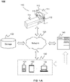
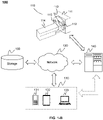
- FIGS. 1-A and 1-B are schematic diagrams illustrating an exemplary CT system 100 according to some embodiments of the present disclosure.
- the CT system 100 may include a CT scanner 110, a network 120, one or more terminals 130, a processing engine 140, and a storage 150.
- the CT scanner 110 may include a gantry 111, a detector 112, a detecting region 113, a table 114, and a radioactive scanning source 115.
- the gantry 111 may support the detector 112 and the radioactive scanning source 115.
- a subject may be placed on the table 114 for scanning.
- the radioactive scanning source 115 may emit radioactive rays to the subject.
- the detector 112 may detect radiation events (e.g., gamma photons) emitted from the detecting region 113.
- the detector 112 may include one or more detector units.
- the detector units may include a scintillation detector (e.g., a cesium iodide detector), a gas detector, etc.
- the detector unit may be and/or include a single-row detector and/or a multi-rows detector.
- the network 120 may include any suitable network that can facilitate exchange of information and/or data for the CT system 100.
- one or more components of the CT system 100 e.g., the CT scanner 110, the terminal 130, the processing engine 140, the storage 150, etc.
- the processing engine 140 may obtain image data from the CT scanner 110 via the network 120.
- the processing engine 140 may obtain user instructions from the terminal 130 via the network 120.
- the network 120 may be and/or include a public network (e.g., the Internet), a private network (e.g., a local area network (LAN), a wide area network (WAN)), etc.), a wired network (e.g., an Ethernet network), a wireless network (e.g., an 802.11 network, a Wi-Fi network, etc.), a cellular network (e.g., a Long Term Evolution (LTE) network), a frame relay network, a virtual private network (“VPN”), a satellite network, a telephone network, routers, hubs, witches, server computers, and/or any combination thereof.
- a public network e.g., the Internet
- a private network e.g., a local area network (LAN), a wide area network (WAN)
- a wired network e.g., an Ethernet network
- a wireless network e.g., an 802.11 network, a Wi-Fi network, etc.
- a cellular network
- the network 120 may include a cable network, a wireline network, a fiber-optic network, a telecommunications network, an intranet, a wireless local area network (WLAN), a metropolitan area network (MAN), a public telephone switched network (PSTN), a Bluetooth TM network, a ZigBee TM network, a near field communication (NFC) network, or the like, or any combination thereof.
- the network 120 may include one or more network access points.
- the network 120 may include wired and/or wireless network access points such as base stations and/or internet exchange points through which one or more components of the CT system 100 may be connected to the network 120 to exchange data and/or information.
- the terminal(s) 130 may include a mobile device 131, a tablet computer 132, a laptop computer 133, or the like, or any combination thereof.
- the mobile device 131 may include a smart home device, a wearable device, a mobile device, a virtual reality device, an augmented reality device, or the like, or any combination thereof.
- the smart home device may include a smart lighting device, a control device of an intelligent electrical apparatus, a smart monitoring device, a smart television, a smart video camera, an interphone, or the like, or any combination thereof.
- the wearable device may include a bracelet, a footgear, eyeglasses, a helmet, a watch, clothing, a backpack, a smart accessory, or the like, or any combination thereof.
- the mobile device may include a mobile phone, a personal digital assistance (PDA), a gaming device, a navigation device, a point of sale (POS) device, a laptop, a tablet computer, a desktop, or the like, or any combination thereof.
- the virtual reality device and/or the augmented reality device may include a virtual reality helmet, virtual reality glasses, a virtual reality patch, an augmented reality helmet, augmented reality glasses, an augmented reality patch, or the like, or any combination thereof.
- the virtual reality device and/or the augmented reality device may include a Google Glass TM , an Oculus Rift TM , a Hololens TM , a Gear VR TM , etc.
- the terminal(s) 130 may be part of the processing engine 140.
- the processing engine 140 may process CT data (e.g., a plurality of image slices) obtained from the CT scanner 110, the terminal 130, and/or the storage 150. For example, the processing engine 140 may identifying a plurality of vertebrae in the plurality of image slices. In some embodiments, the processing engine 140 may be a single server or a server group. The server group may be centralized or distributed. In some embodiments, the processing engine 140 may be local or remote from other components in the CT system 100. The processing engine 140 may access CT data stored in the CT scanner 110, the terminal 130, and/or the storage 150 via the network 120. Alternatively, the processing engine 140 may be directly connected to the CT scanner 110, the terminal 130 and/or the storage 150 to access stored CT data.
- CT data e.g., a plurality of image slices
- the processing engine 140 may be implemented on a cloud platform.
- the cloud platform may include a private cloud, a public cloud, a hybrid cloud, a community cloud, a distributed cloud, an inter-cloud, a multi-cloud, or the like, or any combination thereof.
- the processing engine 140 may be implemented by a computing device 200 having one or more components as illustrated in FIG. 2 .
- the storage 150 may store data, instructions, and/or any other information. In some embodiments, the storage 150 may store data obtained from the terminal 130 and/or the processing engine 140. In some embodiments, the storage 150 may store data and/or instructions that the processing engine 140 may execute or use to perform exemplary methods described in the present disclosure. In some embodiments, the storage 150 may include a mass storage, a removable storage, a volatile read-and-write memory, a read-only memory (ROM), or the like, or any combination thereof. Exemplary mass storage may include a magnetic disk, an optical disk, a solid-state drive, etc. Exemplary removable storage may include a flash drive, a floppy disk, an optical disk, a memory card, a zip disk, a magnetic tape, etc.
- Exemplary volatile read-and-write memory may include a random access memory (RAM).
- RAM may include a dynamic RAM (DRAM), a double date rate synchronous dynamic RAM (DDR SDRAM), a static RAM (SRAM), a thyristor RAM (T-RAM), and a zero-capacitor RAM (Z-RAM), etc.
- Exemplary ROM may include a mask ROM (MROM), a programmable ROM (PROM), an erasable programmable ROM (EPROM), an electrically erasable programmable ROM (EEPROM), a compact disk ROM (CD-ROM), and a digital versatile disk ROM, etc.
- the storage 150 may be implemented on a cloud platform.
- the cloud platform may include a private cloud, a public cloud, a hybrid cloud, a community cloud, a distributed cloud, an inter-cloud, a multi-cloud, or the like, or any combination thereof.
- the storage 150 may be connected to the network 120 to communicate with one or more other components in the CT system 100 (e.g., the processing engine 140, the terminal 130, etc.). One or more components in the CT system 100 may access the data or instructions stored in the storage 150 via the network 120. In some embodiments, the storage 150 may be directly connected to or communicate with one or more other components in the CT system 100 (e.g., the processing engine 140, the terminal 130, etc.). In some embodiments, the storage 150 may be part of the processing engine 140.
- FIG. 2 is a schematic diagram illustrating an exemplary computing device 200 on which the CT system 100 can be implemented, according to some embodiments of the present disclosure.
- the computing device 200 may be a general purpose computer or a special purpose computer. Both may be used to implement a CT system of the present disclosure.
- the computing device 200 may be used to implement any component of the service as described herein.
- the processing engine 140 of the CT system may be implemented on the computing device 200, via its hardware, software program, firmware, or a combination thereof.
- the computer functions related to the CT system as described herein may be implemented in a distributed manner on a number of similar platforms to distribute the processing load.
- the computing device 200 may include COM ports 250 connected to and from a network (e.g., the network 120) connected thereto to facilitate data communications.
- the computing device 200 may also include a central processing unit (CPU) 220, in the form of one or more processors, for executing program instructions.
- the exemplary computer platform may include an internal communication bus 210, program storage and data storage of different forms, for example, a disk 270, and a read only memory (ROM) 230, or a random access memory (RAM) 240, for various data files to be processed and/or transmitted by the computer.
- the exemplary computer platform may also include program instructions stored in the ROM 230, the RAM 240, and/or other type of non-transitory storage medium to be executed by the CPU 220.
- the methods and/or processes of the present disclosure may be implemented as the program instructions.
- the computing device 200 also includes an I/O component 260, supporting input/output between the computer and other components therein.
- the computing device 200 may also receive programming and data
- the computing device 200 in the present disclosure may also include multiple CPUs and/or processors, thus operations and/or method steps that are performed by one CPU and/or processor as described in the present disclosure may also be jointly or separately performed by the multiple CPUs and/or processors.
- the CPU and/or processor of the computing device 200 executes both step A and step B.
- step A and step B may also be performed by two different CPUs and/or processors jointly or separately in the computing device 200 (e.g., the first processor executes step A and the second processor executes step B, or the first and second processors jointly execute steps A and B).
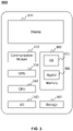
- FIG. 3 is a schematic diagram illustrating exemplary hardware and/or software components of an exemplary mobile device 300 on which the terminal 130 may be implemented according to some embodiments of the present disclosure.
- the mobile device 300 may include a communication platform 310, a display 320, a graphic processing unit (GPU) 330, a central processing unit (CPU) 340, an I/O 350, a memory 360, and a storage 390.
- any other suitable component including but not limited to a system bus or a controller (not shown), may also be included in the mobile device 300.
- a mobile operating system 370 e.g., iOS TM , Android TM , Windows Phone TM , etc.
- the applications 380 may include a browser or any other suitable mobile apps for receiving and rendering information relating to image processing or other information from the processing engine 140.
- User interactions with the information stream may be achieved via the I/O 350 and provided to the processing engine 140 and/or other components of the CT system 100 via the network 120.
- computer hardware platforms may be used as the hardware platform(s) for one or more of the elements described herein.
- a computer with user interface elements may be used to implement a personal computer (PC) or any other type of work station or terminal device.
- PC personal computer
- a computer may also act as a server if appropriately programmed.
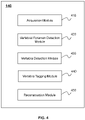
- FIG. 4 is a block diagram illustrating an exemplary processing engine according to some embodiments of the present disclosure.
- the processing engine 140 may include an acquisition module 410, a vertebra foramen detection module 420, a vertebra detection module 430, a vertebra tagging module 440 and a reconstruction module 450.
- the processing engine 140 may be implemented on various components (e.g., the processor 210 of the computing device 200 as illustrated in FIG. 2 ). More or less components may be included in the processing engine 140 without loss of generality. For example, two of the modules may be combined into a single module, or one of the modules may be divided into two or more modules. In one implementation, one or more of the modules may reside on a same or different computing devices (e.g., different server computers).
- the acquisition module 410 may acquire CT data related to a region of interest, for example, a vertebral column.
- the vertebral column may include a plurality of vertebrae.
- Each of the plurality of vertebrae may include a vertebral foramen, a vertebral body, a vertebral arch, etc.
- the plurality of vertebrae may be classified into one or more types.
- the one or more types may include cervical vertebrae (including seven vertebrae), thoracic vertebrae (including twelve vertebrae), lumbar vertebrae (including five vertebrae), sacral vertebrae (including five vertebrae), and coccygeal vertebrae (including three or four vertebrae).
- the CT data may be in the manner of Digital Imaging and Communication in Medicine (DICOM).
- the CT data may include three dimensional (3D) images, two dimensional (2D) images, etc.
- the 3D images may include a stack of 2D images (e.g., a stack of image slices).
- the CT data may include a plurality of image slices in the transverse plane (also referred to herein "transverse plane image").
- the transverse plane is an anatomical plane that divides a body into superior and inferior parts.
- the plurality of image slices may be marked in an organized manner (e.g., sequentially numbered based on the position of organs/tissues presented in the image slices).
- the plurality of image slices may be numbered sequentially as 1 st , 2 nd , ..., n th in the slice direction (also referred to "Z axis").
- the slice direction may refer to the head to feet direction or the feet to head direction.
- the 1 st , 2 nd , ..., n th may refer to slice identifiers of the plurality of image slices.
- a slice with a slice identifier n th may be describes the n th image slice.
- the vertebra foramen detection module 420 may identify one or more vertebral foramina.
- the vertebra foramen detection module 420 may identify the one or more vertebral foramina in a plurality of image slices.
- the vertebra foramen detection module 420 may identify the one or more vertebral foramina by a classifier.
- the classifier may identify a section in which the one or more vertebral foramina may locate.
- the vertebra detection module 430 may determine a plurality of vertebrae. In some embodiments, each of the plurality of vertebrae may be included in one or more image slices. In some embodiments, the vertebra detection module 430 may determine the plurality of vertebrae based on one or more vertebral foramina (e.g., identified by the vertebral foramen detection module 420) and at least one reference point. The plurality of vertebrae may be identified based on a relative position of the plurality of vertebrae and a position of the at least one reference point. Alternatively or additionally, the vertebra detection module 430 may determine the plurality of vertebrae based on a quantity of the plurality of vertebrae.
- the vertebra tagging module 440 may tag a plurality of vertebrae.
- the vertebra tagging module 440 may determine a plurality of serial numbers of the plurality of vertebrae. For the purposes of illustration, each vertebra in a type of vertebrae may be assigned to a serial number.
- the serial number may refer to a rank of position in the type of vertebrae. For example, the serial number of the first vertebra in the cervical vertebrae may be 1 st .
- the vertebra tagging module 440 may further tag the plurality of vertebrae based on the plurality of serial numbers.
- the reconstruction module 450 may reconstruct an image.
- the image may include a sagittal plane image, a transverse plane image, a coronal plane image, or a combination thereof.
- the sagittal plane is an anatomical plane that divides a body into left and right parts.
- the coronal plane is an anatomical plane that divides a body into front and back parts.
- the reconstruction module 450 may reconstruct a sagittal plane image of a plurality of vertebrae. Additionally, the reconstruction module 450 may reconstruct the sagittal plane image based on a spinal cord in a plurality of vertebral foramina.
- one or more modules illustrated in FIG. 4 may be implemented in at least part of the exemplary CT system as illustrated in FIGS. 1-A and 1-B .
- the acquisition module 410, the vertebra foramen detection module 420, the vertebra detection module 430, the vertebra tagging module 440 and/or the reconstruction module 450 may be integrated into a console (not shown).
- a console Via the console, a user may set parameters for scanning an object, controlling imaging processes, controlling parameters for reconstruction of an image, viewing reconstructed images, etc.
- the console may be implemented via the processing engine 140 and/or the terminal 130.
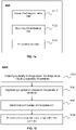
- FIG. 5 is a flowchart illustrating an exemplary process 500 for reconstructing a sagittal plane image according to some embodiments of the present disclosure.
- Process 500 may be performed by processing logic that comprises hardware (e.g., circuitry, dedicated logic, programmable logic, microcode, etc.), software (e.g., instructions run on a processing device to perform hardware simulation), or a combination thereof.
- processing logic may be performed by or be implemented on the processing engine 140 of the CT system 100.
- a plurality of image slices related to a vertebral column are acquired.
- the acquisition of the plurality of image slices may be performed by the acquisition module 410.
- the vertebral column includes a plurality of vertebrae.
- the vertebral column may include a whole vertebral column of a human body or a segmentation thereof (e.g., cervical vertebrae, thoracic vertebrae, lumbar vertebrae, etc.).
- Each of the image slices is a transverse plane image.
- each of the plurality of image slices may be associated with a slice identifier.
- the slice identifier may include one or more numbers, characters, symbols, etc. that can be used to identify the image slice. For example, the slice identifier of the first image slice of the plurality of image slices may be "1."
- one or more vertebral foramina in the plurality of image slices may be identified.
- the identification of the one or more vertebral foramina may be performed by the vertebral foramen detection module 420.
- one or more vertebral foramina with a characteristic boundary may be identified.
- the characteristic boundary of a vertebral foramen may include a boundary that can be recognized by a program.
- the characteristic boundary may include a complete or substantially complete boundary of a vertebral foramen.
- substantially complete boundary may refer to a boundary having a significant amount of similarity with the complete boundary. In some embodiments, the substantially complete boundary may have no lower than 60%, or 70%m, or 80%, or 90%, or 95% of similarity with the complete boundary.
- one or more of the vertebral foramina may be identified using a classifier.
- the classifier may determine one or more sections having the one or more vertebral foramina.
- the section may include a rectangular shape, a circular shape, or any other suitable shape.
- the plurality of vertebrae may be determined based on the one or more vertebral foramina.
- the determination of the plurality of vertebrae may be performed by the vertebra detection module 430.
- the vertebra detection module 430 may divide the one or more vertebral foramina into one or more groups.
- the vertebra detection module 430 may determine the plurality of vertebrae based on the groups.
- the vertebra detection module 430 may determine the plurality of vertebrae based on a threshold.
- the threshold may be a theoretical quantity of vertebrae.
- the vertebra detection module 430 may compare the quantity of the determined vertebrae with the threshold. In response to the determination that the quantity of the determined vertebrae is less than the threshold, the vertebra detection module 430 may continue the process of determining the vertebrae.
- a sagittal plane image of the vertebral column may be reconstructed based on the plurality of vertebrae.
- the reconstruction of the sagittal plane image may be performed by the reconstruction module 450.
- the sagittal plane image may be reconstructed based on a spinal cord corresponding to the plurality of vertebrae.
- the sagittal plane may locate at a boundary of the spinal cord.
- the boundary of the spinal cord may be represented by X coordinates in the sagittal plane, where the X axis may point from the right part towards the left part of a patient, as shown in FIG. 18 .
- the plurality of vertebrae may be tagged based on the sagittal plane image.
- the tagging of the plurality of vertebrae may be performed by the vertebra tagging module 440.
- the plurality of vertebrae may be segmented based on the sagittal plane image of the vertebral column. Then, the location of each of the plurality of vertebrae may be determined. The vertebrae may be tagged based on the location of each of the vertebrae.
- each of the plurality of vertebrae may correspond to a range of slice identifiers, such as "from slice identifier 1 to slice identifier 4.”
- the tag may take form of "serial number + type of vertebrae".
- one vertebra may be described as 1 s t cervical vertebra, 1 st thoracic vertebrae, etc.
- the tags of cervical vertebrae may be marked as C1, C2, ..., C7.
- the tags of thoracic vertebrae may be marked as T1, T2, ..., T12.
- the tags of lumbar vertebrae may be marked as L1, L2, ..., L5.
- the tags of sacral vertebrae may be marked as S1, S2, ..., S5.
- the tags of coccygeal vertebrae may be marked as Co1, Co2, ..., Co4.
- operation 504 may be unnecessary and may be omitted.
- the tagging of the plurality of vertebrae may be performed directly based on operation 503.
- operation 505 may be performed prior to operation 504.
- FIG. 6 is a block diagram illustrating an exemplary vertebral foramen detection module 420 according to some embodiments of the present disclosure.
- the vertebral foramen detection module 420 may include a region identification unit 610, a classification unit 620, and a section determination unit 630. More or less components may be included in the processing engine without loss of generality. For example, two of the modules may be combined into a single module, or one of the modules may be divided into two or more modules. One or more of the modules may reside on a same or different computing devices (e.g., different server computers).
- the region identification unit 610 may identify a target region corresponding to an image slice.
- the target region may be a region of a patient to which the image slice corresponds.
- the target region may include a neck, a chest, a waist, or the like, or a combination thereof.
- the region identification unit 610 may identify a target region based on an anatomical position of an organ (e.g., a basis cranii, a lung, a liver) in the image slice.
- the region identification unit 610 may further identify the type of a vertebra in the image slice based on the target region. For example, in response to determining the target region corresponding to the image slice is neck, the region identification unit 610 may identify the vertebra in one or more images as cervical vertebrae.
- the classification unit 620 may identify a vertebra foramen in an image slice.
- the classification unit 620 may identify one or more sections in the image slice. Each of the one or more sections may refer to a regular or irregular section including a vertebral foramen in the image slice.
- the one or more sections may include a rectangular shape, a circular shape, or any suitable shape.
- the classification unit 620 may include one or more classifiers.
- the classification unit 620 may include different classifiers for identifying different types of vertebrae, such as a classifier for identifying cervical vertebrae, a classifier for identifying thoracic vertebrae, a classifier for identifying lumbar vertebrae, etc.
- the classifiers may be selected based on a target region (e.g., a target region identified by the region identification unit 610). For example, in response to determining that the target region is a chest, a classifier for identifying thoracic vertebrae may be used. Alternatively, the classification unit 620 may identify different types of vertebrae by a same classifier.
- the section determination unit 630 may determine a target section in an image slice.
- the section determination unit 630 may determine the target section based on a plurality of sections (e.g., a plurality of sections identified by the classification unit 620).
- the section determination unit 630 may select one of the plurality of sections as the target section.
- the section determination unit 630 may select the target section randomly from the plurality of sections.
- the section determination unit 630 may rank the plurality of sections and select the target section based on the ranking.
- the sections may be ranked based on coordinates of the plurality of sections.
- the coordinates of a section may include the coordinates of pixels in the section.
- the section determination unit 630 may determine the target section by determining a weighted average of the plurality of sections. In some embodiments, the section determination unit 630 may determine an overlapping section or a collective section of the plurality of sections as the target section. In some embodiments, the section determination unit 630 may further identify a vertebral foramen based on the target section.
- FIG. 7 is a flowchart illustrating an exemplary process 700 for identifying one or more vertebral foramina according to some embodiments of the present disclosure.
- Process 700 may be performed by processing logic that comprises hardware (e.g., circuitry, dedicated logic, programmable logic, microcode, etc.), software (e.g., instructions run on a processing device to perform hardware simulation), or a combination thereof.
- process 700 may be performed in connection with 502 as described in FIG. 5 .
- Process 700 may be performed by the vertebral foramen detection module 420.
- an image slice of a plurality of image slices may be acquired.
- the acquisition of the image slice may be performed by the acquisition module 410.
- the plurality of image slices may relate to a vertebral column.
- a target region of a patient corresponding to the image slice may be identified.
- the identification of the target region may be performed by the region identification unit 610.
- the target region may include a neck, a chest, a waist, or the like, or a combination thereof.
- the target region may be identified based on an anatomical position of an organ (e.g., a basis cranii, a lung, a liver) in a plurality of image slices. For example, if a plurality of image slices includes a basis cranii or a portion thereof, the target region corresponding to the plurality of image slices may be determined as including a neck.
- the target region corresponding to the image slice may be determined as including a chest.
- the identification of the target region may be performed automatically by, for example, the region identification unit 601, or manually by a user.
- one or more sections in the image slice may be identified based on the target region.
- the identification of the one or more sections may be performed by classification unit 620.
- the classification unit 620 may include different classifiers for identifying different target regions (e.g., different types of vertebrae), such as a classifier for identifying cervical vertebrae, a classifier for identifying thoracic vertebrae, a classifier for identifying lumbar vertebrae, etc.
- the identified one or more sections may be a rectangular section including a vertebral foramen.
- process 700 may determine whether there is another image slice to be processed. In response to determining that there is another image slice to be processed, process 700 may loop back to 701 to acquire a new image slice of the plurality of image slices. For example, the next image slice may be acquired for processing. As another example, a random image slice may be acquired for processing. Process 700 can then perform operations described in connection with steps 702 and 703. For example, process 700 can identify a target region of the patient corresponding to the new image slice. Process 700 can also identify one or more sections in the new image slice based on the identified target region.
- process 700 may proceed to 705.
- one or more vertebral foramina in the plurality of image slices may be identified.
- the identification of the one or more vertebral foramina may be performed by the section determination unit 630.
- one or more vertebral foramina may by identified based on one or more sections identified in 703.
- one or more vertebra foramina may be identified in connection with the determination of a target section as described elsewhere in the disclosure.
- the target section may be determined by performing a weighted average of the plurality of sections.
- an overlapping section or a collective section of the plurality of sections may be determined as the target section.
- one or more vertebral foramina may be identified in a portion of or all of the image slices.
- process 700 may identify vertebral foramina in the plurality of image slices simultaneously.
- FIG. 8 is a block diagram illustrating an exemplary classifier unit according to some embodiments of the present disclosure.
- the classification unit 620 may include a feature block 810, a sample block 820, a design block 830, and a classifier 840. More or less components may be included in the classification unit 620 without loss of generality. For example, two of the modules may be combined into a single module, or one of the modules may be divided into two or more modules. One or more of the modules may reside on a same or different computing devices (e.g., different server computers).
- the feature block 810 may generate one or more features for training, validating, and/or testing one or more classifiers (e.g., the classifier 840) and/or perform vertebrae identification using the classifiers.
- the features may be and/or include, for example, one or more features of a vertebral foramen, a neighboring anatomic structure of a vertebral foramen, or the like, or a combination thereof.
- the features of a vertebral foramen may include one or more features representative of the texture of the vertebral foramen, a distribution of brightness of the vertebral, a pixel value (e.g., CT value) distribution of the vertebral foramen, or the like, or a combination thereof.
- the neighboring anatomic structures may include a vertebral body, a vertebral arch, or the like.
- the features of the vertebral foramen may be obtained by processing image data related to a vertebral foramen (e.g., an image slice, a portion of an image slice, etc. including the vertebral foramen), such as multiplying the image data by a convolution kernel.
- the features may include a Harr feature, an average value of pixel values, a representation of edge features, etc.
- the sample block 820 may acquire one or more samples related to a region of interest (e.g., a vertebral foramen).
- the samples may be acquired based on a plurality of image slices related to the region of interest (e.g., acquired by the acquisition module 410).
- Each of the samples may include and/or correspond to an image slice, one or more portions of the image slice, etc.
- the samples may include one or more positive samples and/or negative samples.
- a positive sample may be a sample that includes desired image data related to the region of interest (e.g., image data including a complete vertebral foramen).
- a complete vertebral foramen may have a complete or substantially complete boundary of a vertebral foramen.
- substantially complete boundary may refer to a boundary having a significant amount of similarity with the complete boundary.
- the positive samples may include one or more samples as illustrated in connection with FIGS. 16-B and 16-E below.
- a negative sample may be a sample that does not include desired image data of the region of interest (e.g., image data including an incomplete vertebral foramen or no vertebral foramen).
- the negative samples may include one or more examples as illustrated in connection with FIGS. 16-A, 16-C , and 16-D below.
- the design block 830 may train one or more classifiers (e.g., the classifier 840) for vertebrae identification.
- the design block 830 may train the classifiers based on one or more features (e.g., set by the feature block 810) and/or samples (e.g., acquired by the sample block 820).
- the design block 830 may train the classifiers using one or more machine learning techniques, such as an Expectation-Maximization (EM) algorithm, an Apriori method, a K-Nearest Neighbor algorithm (KNN), an Adaptive Boosting (Adaboost) algorithm, etc.
- the classifiers may include, for example, a Support Vector Machine (SVM), a neutral network, a Naive Bayes classifier, etc.
- SVM Support Vector Machine
- Naive Bayes classifier etc.
- the classifier 840 may identify a region of interest.
- the region of interest may include a vertebral foramen (e.g., as illustrated in FIG. 17-B ).
- the region of interest may be presented in the form of a section in an image slice.
- the classifier 840 may identify one or more sections in an image slice (e.g., as illustrated in FIG. 17-E ).
- FIG. 9 is a flowchart illustrating an exemplary process 900 for identifying a plurality of sections in an image slice according to some embodiments of the present disclosure.
- Process 900 may be performed by processing logic that comprises hardware (e.g., circuitry, dedicated logic, programmable logic, microcode, etc.), software (e.g., instructions run on a processing device to perform hardware simulation), or a combination thereof.
- process 900 may be performed in connection with step 703 as described in FIG. 7 .
- Process 900 may be performed by the classification unit 620.
- one or more features may be generated to train a classifier for vertebrae identification.
- the features may be generated by the feature block 810.
- the one or more features may be generated based on one or more features of a vertebral foramen, a neighboring anatomic structure of a vertebral foramen, or the like, or a combination thereof.
- the one or more features may include a Harr feature, an average value of pixel values, a representation of edge features, etc.
- a plurality of samples may be acquired.
- the acquisition of the plurality of samples may be performed by the sample block 820.
- the plurality of samples may be acquired from plurality of image slices related to a region of interest.
- the plurality of samples may include a plurality of positive samples and a plurality of negative samples.
- the classifier may be trained based on the one or more features of the classifier and the plurality of samples.
- the training of the classifier may be performed by the design block 830.
- the method of training the classifier may include a machine learning method (e.g., EM, KNN, Adaboost, etc.)
- a plurality of sections in an image slice may be identified via the classifier.
- the identifying of the plurality of sections may be performed by the classifier 840.
- each of the plurality of sections may include a rectangular section including a complete vertebral foramen (as illustrated in FIG. 17-B ).
- FIG. 10 is a block diagram illustrating an exemplary vertebra detection module 430 according to some embodiments of the present disclosure.
- the vertebra detection module 430 may include a group unit 1010, a reference unit 1020, a determination unit 1030, a segmentation unit 1040, and a quantity unit 1050. More or less components may be included in the processing engine without loss of generality. For example, two of the modules may be combined into a single module, or one of the modules may be divided into two or more modules. In one implementation, one or more of the modules may reside on a same or different computing devices (e.g., different server computers).
- the group unit 1010 may divide a plurality of image slices into one or more groups.
- Each of the plurality of image slices may include a vertebral foramen with a characteristic boundary.
- a group of image slices may include at least one image slice related to a vertebral foramen with a complete boundary.
- a group of image slices can include any suitable number of image slices, such as one, two, three, or any other positive number of image slices.
- the image slices may include one or more image slices corresponding to the vertebral foramina identified by, for example, the classifier 840.
- the boundary of a vertebral foramen in the plurality of image slices may appear gradually and disappear gradually (e.g., as illustrated in FIGS.
- a group of image slices may include an identified vertebral foramen (e.g., a vertebral foramen with a complete boundary).
- the image slices may include successive image slices (e.g., image slices that are associated with successive slice identifiers).
- the reference unit 1020 may determine at least one reference point in one or more image slices.
- the one or more image slices may relate to a plurality of vertebral foramina or vertebrae.
- the reference unit 1020 may determine the at least one reference point based on an anatomical position of an organ or tissue in the plurality of image slices. For example, the reference unit 1020 may determine the bottom of the cranii, which is connected to a cervical vertebra in anatomy, as the reference point.
- the determination unit 1030 may determine a plurality of vertebrae in a plurality of image slices. In some embodiments, the determination unit 1030 may determine each of the plurality of vertebrae based on one or more groups of image slices divided by the group unit 1010. For example, the determination unit 1030 may update a group of image slices by adding one or more image slices with no vertebral foramen to the group. The updated group of image slices may correspond to the same vertebra. The added one or more image slices may include successive image slices of the image slices in the group.
- the number of image slices may be determined based on a thickness of the corresponding vertebra. For example, if the second cervical vertebra in anatomy is to be determined, the determination unit 1030 may determine a specific thickness (e.g., 50 mm for the second cervical) along the slice direction. The determination unit 1030 may further determine a number of image slices that add up to the specific thickness. For purposes of illustration, in response to determining thickness of a specific vertebra is 50 mm and the slice interval is 0.5 mm, the number of the image slices corresponding to the specific vertebra may be 100. The slice interval may refer to a distance between the centers of two adjacent image slices along the slice direction.
- the segmentation unit 1040 may determine a vertebra based on a plurality of image slices by segmenting the image slices.
- the segmentation may be performed using thresholding techniques, edge detection techniques, region-growing techniques, histogram-based techniques, and/or any other image segmentation techniques.
- the segmentation unit 1040 may segment a vertebra by thresholding the image slices based on a threshold.
- the threshold may be determined based on a CT value corresponding to a vertebra. More particularly, for example, the threshold may be determined based on a CT value corresponding to a vertebral foramen (e.g., a target section in an image slice).
- the CT value corresponding to a vertebra may be in a predetermined range (e.g., a range from 150 HU to 1000 HU or any other suitable range).
- the quantity unit 1050 may determine the number of vertebrae determined by the determination unit 1030 and/or the segmentation unit 1040. In some embodiments, the number of vertebrae may be the same as the number of groups of image slices divided by the group unit 1010. In some embodiments, the quantity unit 1050 may determine whether the number of vertebrae determined by the determination unit 1030 is equal to a threshold.
- the threshold may be a predetermined number of vertebrae in a region of interest.
- FIG. 11 is a flowchart illustrating an exemplary process 1100 for determining a plurality of vertebrae according to some embodiments of the present disclosure.
- Process 1100 may be performed by processing logic that comprises hardware (e.g., circuitry, dedicated logic, programmable logic, microcode, etc.), software (e.g., instructions run on a processing device to perform hardware simulation), or a combination thereof.
- process 1100 may be performed in connection with step 503 as described in FIG. 5 .
- Process 1100 may be performed by the vertebra detection module 430.
- a plurality of image slices may be acquired.
- the plurality of image slices may include one or more vertebral foramina that are identified by, for example, the classifier 840.
- the acquisition of the plurality of image slices may be performed by the acquisition module 410.
- the one or more vertebral foramina may be divided into one or more groups.
- the division of the one or more vertebral foramina may be performed by the group unit 1010.
- each of the one or more groups may include at least one vertebral foramen with a complete boundary.
- a group of vertebral foramina may be one, two, three, or any suitable positive number of vertebral foramina.
- the one or more vertebral foramina may be divided based on the positions of each vertebral foramen.
- the group unit 1010 may determine vertebral foramina associated with successive slice identifiers (i.e., successive image slices) among the one or more vertebral foramina into the same group.
- the position of an image slice or a vertebral foramen in the image slice may be identified by a slice identifier.
- At least one reference point may be determined based on the plurality of image slices.
- the determination of the at least one reference point may be performed by the reference unit 1020.
- the at least one reference point may be determined based on an anatomical position of an organ or tissue (e.g., a basis, cranii, a lung, a liver, a heart, a kidney, a stomach, etc.) in the plurality of image slices.
- an organ or tissue e.g., a basis, cranii, a lung, a liver, a heart, a kidney, a stomach, etc.
- the bottom of the cranii which is connected to a cervical vertebra in anatomy as the reference point.
- a plurality of vertebrae may be determined based on the one or more groups of vertebral foramina or the at least one reference point. The determination of the plurality of vertebrae may be performed by the determination unit 1030 and/or the segmentation unit 1040.
- vertebral foramina in a same group may correspond to a same vertebra.
- a specific image slice with no vertebral foramen identified may correspond to the same vertebra when the specific image slice has a successive slice identifier with the vertebral foramina in the same group.
- vertebral foramina may be identified in 1 st and 2 nd image slices (i.e., with slice identifiers 1 st , 2 nd ) , while no vertebral foramen is identified in 3 rd image slice.
- the 3 rd image slice may be determined by the determination unit 1030 that it corresponds to a same vertebra with the 1 st and 2 nd image slices.
- each of the plurality of vertebrae may be determined by segmenting the plurality of image slices.
- the segmentation may be performed by the segmentation unit 1040 as described in connection with FIG. 10 .
- process 1100 may determine whether a number of the plurality of vertebrae is equal to a first threshold. The determination may be performed by the quantity unit 1050.
- the first threshold may be a theoretical number of the plurality of vertebrae in anatomy. For example, a theoretical number of cervical vertebrae is seven. A theoretical number of thoracic vertebrae is twelve. A theoretical number of lumbar vertebrae is five. As another example, a theoretical number of cervical vertebrae and thoracic vertebrae may be twelve (i.e., a summation of five and seven).
- process 1100 in response to determining that the number of the plurality of vertebrae is not equal to the first threshold, process 1100 may loop back to 1104 and further determine the number of vertebrae for another iteration.
- the determination unit 1030 may determine that at least two successive vertebrae of the plurality of vertebrae determined in 1104 belong to a same vertebra in anatomy. Then, the determination unit 1030 may further combine image slices corresponding to the at least two of the plurality of vertebrae and determine a same vertebra. In some embodiments, whether two successive vertebrae belong to a same vertebra may be determined based on a distance between the two successive vertebrae. For the purposes of illustration, the two successive vertebrae may include an anterior vertebra and a posterior vertebra in anatomy along the slice direction.
- the determination unit 1030 may determine that the two successive vertebrae belong to a same vertebra.
- the distance between the two successive vertebrae may refer to the distance between the centers of the last image slice of the anterior vertebra and the last image slice of the posterior vertebra along the slice direction.
- the second threshold may be determined based on a theoretical distance.
- the determination unit 1030 may further determine one or more vertebrae, such as determining one or more vertebrae in successive image slices other than those having a vertebra. In some embodiments, in response to determining that a number of the successive image slices is greater than a third threshold, the determination unit 1030 may determine one or more vertebrae in the successive image slices.
- the third threshold may be determined based on a theoretical number of image slices between two successive vertebrae.
- process 1100 may proceed to 1106 and obtain the plurality of vertebrae.
- the plurality of vertebrae may be stored in a storage device (e.g., the storage 150) for subsequent usage.
- FIG. 12 is a block diagram illustrating an exemplary vertebra tagging module 440 according to some embodiments of the present disclosure.
- the vertebra tagging module 440 may include a label unit 1210 and a tag unit 1220. More or less components may be included in the processing engine without loss of generality. For example, two of the modules may be combined into a single module, or one of the modules may be divided into two or more modules. In one implementation, one or more of the modules may reside on a same or different computing devices (e.g., different server computers).
- the label unit 1210 may label a plurality of vertebrae in a plurality of image slices and/or a sagittal plane image of a vertebra column.
- the label 1210 may label each of the vertebrae by associating the vertebra with one or more labels.
- Each of the marks may include one or more colors (e.g., "red,” “yellow,” “blue,” “purple,” etc.), overstriking, etc.
- the label unit 1210 may label the plurality of vertebrae by performing one or more operations described in connection with FIG. 18 .
- the tag unit 1220 may tag a plurality of vertebrae. Each of the plurality of vertebrae may be associated with a tag.
- the tag associated with a vertebra may include information about an identifier of the vertebra (e.g., a serial number), a type of the vertebrae, and/or any other information related to the vertebra.
- the tag may have any suitable format and may include one or more numbers, symbols, characters, etc.
- the tag unit 1220 may tag the plurality of vertebrae based on at least one reference point. For example, the reference point may be the bottom of the cranii.
- the tag unit 1120 may tag the vertebra under the cranii as the first cervical vertebra (i.e., 1 st cervical vertebra or C1). The tagged vertebra may be used as another reference point to tag one or more other vertebrae.
- the tag unit 1120 may further tag a vertebra next to the first cervical vertebra as the second cervical vertebra (i.e., 2 nd cervical vertebra or C2).
- FIG. 13 is a flowchart illustrating an exemplary process 1300 for tagging vertebrae according to some embodiments of the present disclosure.
- Process 1300 may be performed by processing logic that comprises hardware (e.g., circuitry, dedicated logic, programmable logic, microcode, etc.), software (e.g., instructions run on a processing device to perform hardware simulation), or a combination thereof.
- process 1300 may be performed in connection with step 504 as described in FIG. 5 .
- Process 1300 may be performed by the vertebral tagging module 440.
- a plurality of vertebrae may be labeled.
- the labeling of the plurality of vertebrae may be performed by the label unit 1210.
- the labeling may be performed on a sagittal plane image of the plurality of vertebrae. See, for example, vertical line 1801 in FIG. 18 .
- the location and size of each of the plurality of vertebrae, corresponding to a range of slice identifiers may be determined by, for example, segmenting the plurality of vertebrae on the sagittal plane image.
- Each of the vertebrae may be associated with one or more labels.
- each of the labels may include one or more colors (e.g., "red,” “yellow,” “blue,” “purple,” etc.), overstriking, etc.
- the plurality of vertebrae may be tagged based on the labeled plurality of vertebrae.
- the tagging of the plurality of vertebrae may be performed by the tag unit 1220.
- the tagging of the plurality of vertebrae may be performed orderly when a reference point, such as bottom of the cranii is determined.
- the plurality of vertebrae may be tagged by information about an identifier of the vertebra (e.g., a serial number), a type of the vertebrae, etc.
- a vertebra may be tagged as the second cervical vertebra (i.e., 2 nd cervical vertebra or C2).
- FIG. 14 is a block diagram illustrating an exemplary reconstruction module according to some embodiments of the present disclosure.
- the reconstruction module 450 may include a spinal cord segmentation unit 1410, a boundary determination unit 1420, and a reconstruction unit 1430. More or less components may be included in the processing engine without loss of generality. For example, two of the modules may be combined into a single module, or one of the modules may be divided into two or more modules. In one implementation, one or more of the modules may reside on a same or different computing devices (e.g., different server computers).
- the spinal cord segmentation unit 1410 may segment a spinal cord from a plurality of image slices.
- the spinal cord may reside in the vertebral foramina.
- the spinal cord segmentation unit 1410 may segment the spinal cord using threshing, edge detection, region-growing technique, histogram-based technique, etc., before or after the identification of vertebral foramina.
- the spinal cord segmentation unit 1410 may acquire a plurality of samples from a plurality of sections and/or a plurality of target sections in a plurality of image slices, and perform a region growing based on the plurality of samples.
- the boundary determination unit 1420 determines a boundary of the spinal cord.
- the boundary of the spinal cord is represented by one or more coordinates (e.g., X coordinates and/or Y coordinates) in the transverse plane.
- the coordinates may accord to one or more axes in the transverse plane, such as a first axis (e.g., the X axis) and a second axis (e.g., the Y axis).
- the X axis may point from the right part towards the left part of a patient
- the Y axis may point from the anterior part towards the posterior part of a patient, as shown in FIG. 18 .
- the boundary determination unit 1420 may determine a boundary range of a spinal cord. Then, the boundary determination unit 1420 may determine the boundary of the spinal cord based on the boundary range. For the purposes of illustration, the boundary of a spinal cord may range from a first X coordinate xo to a second X coordinate x 1 along the X axis, and range from a first Y coordinate yo to a second Y coordinate y 1 along the Y axis.
- the reconstruction unit 1430 may reconstruct a sagittal plane image of a vertebral column.
- the sagittal plane image may locate within the boundary of the spinal cord.
- the reconstruction unit 1430 may reconstruct the sagittal plane image at a center of the spinal cord (e.g., an average value of xo and x 1 ).
- FIG. 15 is a flowchart illustrating an exemplary process for reconstructing a sagittal plane image according to some embodiments of the present disclosure.
- Process 1500 may be performed by processing logic that comprises hardware (e.g., circuitry, dedicated logic, programmable logic, microcode, etc.), software (e.g., instructions run on a processing device to perform hardware simulation), or a combination thereof.
- process 1500 may be performed in connection with step 505 as described in FIG. 5 .
- Process 1500 may be performed by the reconstruction module 450.
- a plurality of image slices may be acquired.
- the plurality of image slices may include a plurality of vertebrae.
- the acquisition of the plurality of image slices may be performed by the acquisition module 410.
- the plurality of image slices may be the same with the plurality of image slices acquired in 501.
- a spinal cord may be segmented based on the plurality of vertebrae.
- the segmentation of the spinal cord may be performed by the spinal cord segmentation unit 1410.
- the spinal cord may be segmented using one or more region growing techniques.
- a boundary of the spinal cord may be determined.
- the determination of the boundary may be performed by the boundary determination unit 1420.
- the boundary of the spinal cord may be represented by X coordinate.
- the boundary may be range from a first X coordinate xo to a second X coordinate x 1 .
- process 1500 may determine an X coordinate corresponding to each pixel of a spinal cord. The process 1500 may further determine the boundary of the spinal cord based on the X coordinate.
- a sagittal plane image within the boundary is reconstructed.
- the reconstruction of the sagittal plane image may be performed by the reconstruction unit 1430.
- the sagittal plane image may be reconstructed based on any value of X coordinate within the boundary.
- the sagittal plane image may be reconstructed at a center of the spinal cord (e.g., an average value of xo and x 1 ).
- FIGS. 16-A to 16-C illustrate exemplary transverse plane images of a cervical vertebra, a thoracic vertebrae and a lumbar vertebrae according to some embodiments of the present disclosure.
- a transverse plane image is defined by X axis and/or Y axis in the transverse plane.
- the X axis points from the right part towards the left part of a patient.
- the Y axis points from the anterior part towards the posterior part of a patient.
- a vertebra includes a vertebral foramen, a vertebral body, a vertebral arch, etc.
- the vertebral foramen may be formed by the vertebral body and the vertebral arch.
- the spinal cord passes through the vertebral foramen.
- the vertebral foramen include a complete boundary.
- FIGS. 17-A to 17-E illustrate exemplary transverse plane images of a vertebral foramen according to some embodiments of the present disclosure.
- a transverse plane image is defined by X axis and/or Y axis in the transverse plane.
- the X axis points from the right part towards the left part of a patient.
- the Y axis points from the anterior part towards the posterior part of a patient.
- the transverse plane images are generated along a Z axis (from the feet to the head or from the head to feet with respect to a patient).
- the boundary of the vertebral foramina 1710, 1730, and 1740 is incomplete.
- the boundary of the vertebral foramen 1720 is complete. As illustrated in FIGS. 17-A to 17-D, the boundary of the vertebral foramen appears gradually and becomes complete. Then the boundary of the vertebral foramen disappears gradually.
- the vertebral foramen includes a complete boundary. There are three rectangular sections, each including the vertebral foramen.
- FIG. 18 illustrates an exemplary sagittal plane image of a vertebral column according to some embodiments of the present disclosure.
- the vertebral column includes a plurality of vertebrae. Each of the plurality of vertebrae is labeled by a vertical line (e.g., line 1801).
- the sagittal plane image is defined by Y axis and/or Z axis in the sagittal plane, which is perpendicular to the X axis.
- the X axis points from the right part towards the left part of a patient.
- the Y axis points from the anterior part towards the posterior part of a patient.
- the Z axis points from the inferior part towards the superior part of a patient (i.e., from the feet towards the head).
- aspects of the present disclosure may be illustrated and described herein in any of a number of patentable classes or context including any new and useful process, machine, manufacture, or composition of matter, or any new and useful improvement thereof. Accordingly, aspects of the present disclosure may be implemented entirely hardware, entirely software (including firmware, resident software, micro-code, etc.) or combining software and hardware implementation that may all generally be referred to herein as a "unit,” “module,” or “system.” Furthermore, aspects of the present disclosure may take the form of a computer program product embodied in one or more computer readable media having computer readable program code embodied thereon.
- a computer readable signal medium may include a propagated data signal with computer readable program code embodied therein, for example, in baseband or as part of a carrier wave. Such a propagated signal may take any of a variety of forms, including electro-magnetic, optical, or the like, or any suitable combination thereof.
- a computer readable signal medium may be any computer readable medium that is not a computer readable storage medium and that may communicate, propagate, or transport a program for use by or in connection with an instruction execution system, apparatus, or device.
- Program code embodied on a computer readable signal medium may be transmitted using any appropriate medium, including wireless, wireline, optical fiber cable, RF, or the like, or any suitable combination of the foregoing.
- Computer program code for carrying out operations for aspects of the present disclosure may be written in any combination of one or more programming languages, including an object oriented programming language such as Java, Scala, Smalltalk, Eiffel, JADE, Emerald, C++, C#, VB. NET, Python or the like, conventional procedural programming languages, such as the "C" programming language, Visual Basic, Fortran 2103, Perl, COBOL 2102, PHP, ABAP, dynamic programming languages such as Python, Ruby and Groovy, or other programming languages.
- the program code may execute entirely on the user's computer, partly on the user's computer, as a stand-alone software package, partly on the user's computer and partly on a remote computer or entirely on the remote computer or server.
- the remote computer may be connected to the user's computer through any type of network, including a local area network (LAN) or a wide area network (WAN), or the connection may be made to an external computer (for example, through the Internet using an Internet Service Provider) or in a cloud computing environment or offered as a service such as a Software as a Service (SaaS).
- LAN local area network
- WAN wide area network
- SaaS Software as a Service
Landscapes
- Engineering & Computer Science (AREA)
- Theoretical Computer Science (AREA)
- Computer Vision & Pattern Recognition (AREA)
- General Physics & Mathematics (AREA)
- Physics & Mathematics (AREA)
- Data Mining & Analysis (AREA)
- Artificial Intelligence (AREA)
- Evolutionary Computation (AREA)
- Life Sciences & Earth Sciences (AREA)
- Bioinformatics & Cheminformatics (AREA)
- General Engineering & Computer Science (AREA)
- Evolutionary Biology (AREA)
- Bioinformatics & Computational Biology (AREA)
- Databases & Information Systems (AREA)
- Computing Systems (AREA)
- Health & Medical Sciences (AREA)
- Multimedia (AREA)
- Software Systems (AREA)
- General Health & Medical Sciences (AREA)
- Medical Informatics (AREA)
- Apparatus For Radiation Diagnosis (AREA)
- Image Processing (AREA)
- Magnetic Resonance Imaging Apparatus (AREA)
Claims (10)
- Verfahren zur Identifizierung von Wirbeln, das von einer Rechenvorrichtung ausgeführt wird, die mindestens einem Prozessor einschließt, wobei das Verfahren Folgendes umfasst:Erfassen (501) einer Vielzahl von Bildscheiben, die sich auf eine Wirbelsäule eines Objekts beziehen, wobei die Wirbelsäule eine Vielzahl von Wirbeln einschließt und die Vielzahl von Bildscheiben eine Vielzahl von Bildern in einer Querebene sind, die in einer Querebene des Objekts erfasst wurden;Identifizierung (502), durch den mindestens einen Prozessor, einer oder mehrerer Wirbelfortsätze in der Vielzahl der Bildscheiben unter Verwendung eines Klassifikators;Bestimmen (503), durch den mindestens einen Prozessor, der Vielzahl von Wirbeln in der Vielzahl von Bildscheiben, basierend auf dem einen oder den mehreren Wirbelfortsätzen; undRekonstruieren (504) eines Bildes der Wirbelsäule des Objekts in der Sagittalebene durch den mindestens einen Prozessor, basierend auf der Vielzahl von Wirbeln in der Vielzahl von Bildscheiben, wobei das Rekonstruieren des Bildes in der Sagittalebene umfasst:Segmentieren (1502) eines Rückenmarks basierend auf der Vielzahl von Wirbeln in der Vielzahl von Bildscheiben;Bestimmen (1503) einer Begrenzung des Rückenmarks, wobei die Begrenzung von einer ersten Koordinate zu einer zweiten Koordinate entlang einer Achse in der Querebene des Objekts reicht; undRekonstruieren (1504) des Bildes der Sagittalebene innerhalb der Begrenzung.
- Verfahren nach Anspruch 1, wobei das Identifizieren eines oder mehrerer Wirbellöcher in der Vielzahl von Bildscheiben weiterumfasst:
Detektieren einer Vielzahl von Schnitten in der Vielzahl von Bildscheiben; und Identifizieren des einen oder der mehreren Wirbellöcher basierend auf der Vielzahl von Schnitten. - Verfahren nach Anspruch 2, wobei mindestens eine der mehreren Bildscheiben mehr als einen der mehreren Abschnitte einschließt, wobei jeder der mehr als einen der mehreren Abschnitte ein Wirbelloch aufweist.
- Verfahren nach einem der Ansprüche 1 bis 3, wobei das Bestimmen der Mehrzahl von Wirbeln weiter umfasst:
Unterteilen des einen oder der mehreren Wirbellöcher in eine oder mehrere Gruppen; und Bestimmen der Mehrzahl von Wirbeln basierend auf der einen oder den mehreren Gruppen. - Verfahren nach Anspruch 4, wobei das Bestimmen der Vielzahl von Wirbeln weiter umfasst:Bestimmen mindestens eines Referenzpunktes basierend auf der Vielzahl von Bildscheiben; undBestimmen der Vielzahl von Wirbeln basierend auf einem Abstand zwischen dem Referenzpunkt und des/der identifizierten einen oder mehreren Wirbellöcher.
- Verfahren nach einem der Ansprüche 1 bis 5, weiter umfassend:
Rekonstruieren des Bildes in der Sagittalebene in der Mitte des Rückenmarks basierend auf einem Durchschnittswert der ersten Koordinate und der zweiten Koordinate. - Verfahren nach Anspruch 1, weiter umfassend:
Segmentieren der Vielzahl von Wirbeln basierend auf dem Bild in der Sagittalebene; und Markieren der Vielzahl von Wirbeln. - System zur Identifizierung von Wirbeln, umfassend:mindestens ein computerlesbares Speichermedium, das einen Satz von Anweisungen enthält;mindestens einen Prozessor, der mit dem mindestens einen computerlesbaren Speichermedium in Verbindung steht, wobei der mindestens eine Prozessor beim Ausführen des Satzes von Anweisungen angewiesen wird zum:Erfassen (501) einer Vielzahl von Bildscheiben, die sich auf eine Wirbelsäule eines Objekts beziehen, wobei die Wirbelsäule eine Vielzahl von Wirbeln einschließt, wobei die Vielzahl von Bildscheiben eine Vielzahl von Bildern in einer Querebene ist, die in einer Querebene des Objekts erfasst wurden;Identifizieren (502) eines oder mehrerer Wirbellöcher in der Vielzahl von Bildscheiben unter Verwendung eines Klassifikators; undBestimmen (503) der Vielzahl von Wirbeln in der Vielzahl von Bildscheiben basierend auf dem einen oder den mehreren Wirbellöcher; undRekonstruieren (504) eines Bildes der Wirbelsäule des Objekts in der Sagittalebene basierend auf der Vielzahl von Wirbeln in der Vielzahl von Bildscheiben, wobei zur Rekonstruktion des Bildes in der Sagittalebene der mindestens eine Prozessor weiter angewiesen ist zum:Segmentieren (1502) eines Rückenmarks basierend auf der Vielzahl von Wirbeln in der Vielzahl von Bildscheiben;Bestimmen (1503) einer Begrenzung des Rückenmarks, wobei die Begrenzung von einer ersten Koordinate zu einer zweiten Koordinate entlang einer Achse in der Querebene des Objekts reicht; undRekonstruieren (1504) des Bildes der Sagittalebene innerhalb der Begrenzung.
- System nach Anspruch 8, wobei zum Identifizieren einer oder mehrerer Wirbellöcher in der Vielzahl von Bildscheiben der mindestens eine Prozessor weiter angewiesen ist zum:Detektieren einer Vielzahl von Abschnitten in der Vielzahl von Bildscheiben; undIdentifizieren des einen oder der mehreren Wirbellöcher basierend auf der Vielzahl von Schnitten.
- System nach Anspruch 9, wobei mindestens eine der Vielzahl von Bildscheiben mehr als einen der mehreren Abschnitte einschließt, wobei jeder der mehr als einer der mehrere Abschnitte ein Wirbelloch aufweist.
Applications Claiming Priority (1)
| Application Number | Priority Date | Filing Date | Title |
|---|---|---|---|
| PCT/CN2017/095299 WO2019023891A1 (en) | 2017-07-31 | 2017-07-31 | SYSTEMS AND METHODS FOR AUTOMATIC SEGMENTATION AND IDENTIFICATION OF VERTEBRA IN MEDICAL IMAGES |
Publications (3)
| Publication Number | Publication Date |
|---|---|
| EP3662444A1 EP3662444A1 (de) | 2020-06-10 |
| EP3662444A4 EP3662444A4 (de) | 2020-06-10 |
| EP3662444B1 true EP3662444B1 (de) | 2022-06-29 |
Family
ID=61105564
Family Applications (1)
| Application Number | Title | Priority Date | Filing Date |
|---|---|---|---|
| EP17919925.2A Active EP3662444B1 (de) | 2017-07-31 | 2017-07-31 | Systeme und verfahren zur automatischen wirbelsäulensegmentierung und -identifizierung auf medizinischen bildern |
Country Status (4)
| Country | Link |
|---|---|
| US (1) | US10417768B2 (de) |
| EP (1) | EP3662444B1 (de) |
| CN (2) | CN107633521B (de) |
| WO (1) | WO2019023891A1 (de) |
Families Citing this family (23)
| Publication number | Priority date | Publication date | Assignee | Title |
|---|---|---|---|---|
| US10902587B2 (en) * | 2018-05-31 | 2021-01-26 | GE Precision Healthcare LLC | Methods and systems for labeling whole spine image using deep neural network |
| CN108986891A (zh) * | 2018-07-24 | 2018-12-11 | 北京市商汤科技开发有限公司 | 医疗影像处理方法及装置、电子设备及存储介质 |
| CN109934824B (zh) * | 2019-03-27 | 2021-02-12 | 清华大学 | 颈椎脊髓高信号的检测方法及系统 |
| CN110648329B (zh) * | 2019-03-29 | 2023-12-26 | 中国科学院深圳先进技术研究院 | 一种目标图像提取方法、系统及终端设备 |
| CN110210519B (zh) * | 2019-05-10 | 2021-06-22 | 上海联影智能医疗科技有限公司 | 分类方法、计算机设备和存储介质 |
| CN110110808B (zh) * | 2019-05-16 | 2022-04-15 | 京东方科技集团股份有限公司 | 一种对图像进行目标标注的方法、装置及计算机记录介质 |
| CN110544245B (zh) * | 2019-08-30 | 2020-11-27 | 北京推想科技有限公司 | 图像处理方法、装置、计算机可读存储介质及电子设备 |
| CN110569854B (zh) * | 2019-09-12 | 2022-03-29 | 上海商汤智能科技有限公司 | 图像处理方法及装置、电子设备和存储介质 |
| CN111063424B (zh) | 2019-12-25 | 2023-09-19 | 上海联影医疗科技股份有限公司 | 一种椎间盘数据处理方法、装置、电子设备及存储介质 |
| CN111000580B (zh) * | 2019-12-26 | 2023-05-02 | 东软医疗系统股份有限公司 | 椎间盘扫描方法、装置、控制台设备及ct系统 |
| CN111444978B (zh) * | 2020-04-03 | 2023-06-09 | 王银璇 | 椎体成形术骨水泥渗漏检测方法、系统及存储介质 |
| CN111524188A (zh) * | 2020-04-24 | 2020-08-11 | 杭州健培科技有限公司 | 腰椎定位点获取方法、设备及介质 |
| CN111493918B (zh) * | 2020-04-24 | 2022-08-26 | 杭州健培科技有限公司 | 腰椎ct影像的观测面自动定位方法、应用方法及设备 |
| CN111652862B (zh) * | 2020-05-27 | 2024-09-24 | 联影智能医疗科技(北京)有限公司 | 脊柱顺列分类方法、计算机设备和存储介质 |
| TWI733487B (zh) * | 2020-06-09 | 2021-07-11 | 廣達電腦股份有限公司 | 脊椎壓迫性骨折偵測方法與系統 |
| CN113516614A (zh) * | 2020-07-06 | 2021-10-19 | 阿里巴巴集团控股有限公司 | 脊柱影像的处理方法、模型训练方法、装置及存储介质 |
| CN112184623B (zh) * | 2020-09-01 | 2024-12-24 | 联影智能医疗科技(北京)有限公司 | 脊柱椎体的椎间隙分析方法、设备和存储介质 |
| CN113643314B (zh) * | 2021-07-02 | 2023-09-12 | 阿里巴巴新加坡控股有限公司 | 医学影像中脊柱的分割方法 |
| JP7646488B2 (ja) * | 2021-07-16 | 2025-03-17 | 国立研究開発法人国立がん研究センター | 画像処理装置、方法、プログラム及び記憶媒体 |
| CN114998297A (zh) * | 2022-06-24 | 2022-09-02 | 上海联影医疗科技股份有限公司 | 椎骨编号方法、装置、电子装置和存储介质 |
| CN116416222A (zh) * | 2023-03-16 | 2023-07-11 | 清华大学 | 一种脊柱椎体识别方法、装置及电子设备 |
| CN117257539B (zh) * | 2023-03-28 | 2024-06-14 | 杭州一真医疗器械有限公司 | 数字化颈椎牵引系统 |
| CN116370074B (zh) * | 2023-04-14 | 2026-01-30 | 上海电气集团股份有限公司 | 脊柱截骨路径规划装置、方法和系统 |
Family Cites Families (39)
| Publication number | Priority date | Publication date | Assignee | Title |
|---|---|---|---|---|
| US3420229A (en) * | 1966-10-06 | 1969-01-07 | John W Miller | Osteopathic device |
| US4570640A (en) * | 1981-08-06 | 1986-02-18 | Barsa John E | Sensory monitoring apparatus and method |
| US7393351B2 (en) * | 1995-06-07 | 2008-07-01 | Arthrocare Corporation | Apparatus and methods for treating cervical inter-vertebral discs |
| US6558390B2 (en) * | 2000-02-16 | 2003-05-06 | Axiamed, Inc. | Methods and apparatus for performing therapeutic procedures in the spine |
| US7727263B2 (en) * | 2000-02-16 | 2010-06-01 | Trans1, Inc. | Articulating spinal implant |
| ES2308014T5 (es) * | 2000-02-16 | 2012-03-16 | Trans1, Inc. | Aparato para la distracción y la fusión espinal |
| US7014633B2 (en) * | 2000-02-16 | 2006-03-21 | Trans1, Inc. | Methods of performing procedures in the spine |
| US6899716B2 (en) * | 2000-02-16 | 2005-05-31 | Trans1, Inc. | Method and apparatus for spinal augmentation |
| US6837884B2 (en) * | 2001-06-18 | 2005-01-04 | Arthrocare Corporation | Electrosurgical apparatus having compound return electrode |
| DE102004009658B4 (de) * | 2004-02-27 | 2008-03-27 | Siemens Ag | Verfahren und Vorrichtung zur automatischen Bestimmung der Sagittalebene |
| WO2005088520A1 (en) * | 2004-03-11 | 2005-09-22 | University Of Cincinnati | Automated spine survey iterative scan technique (assist) |
| US8403965B2 (en) * | 2007-01-29 | 2013-03-26 | Polaris Biotechnology, Inc. | Vertebra attachment method and system |
| US20090012614A1 (en) * | 2007-05-08 | 2009-01-08 | Dixon Robert A | Device and method for tethering a spinal implant |
| AU2009322898B2 (en) * | 2008-12-05 | 2015-03-12 | Spr Therapeutics, Inc. | Systems and methods to place one or more leads in tissue to electrically stimulate nerves of passage to treat pain |
| CN102018525B (zh) | 2009-09-23 | 2013-06-05 | 上海西门子医疗器械有限公司 | 椎骨和椎间盘的定位方法和装置 |
| US9020235B2 (en) * | 2010-05-21 | 2015-04-28 | Siemens Medical Solutions Usa, Inc. | Systems and methods for viewing and analyzing anatomical structures |
| CN102727200B (zh) * | 2011-03-31 | 2016-03-30 | 深圳迈瑞生物医疗电子股份有限公司 | 脊柱椎体和椎间盘分割方法、装置、磁共振成像系统 |
| US8891848B2 (en) * | 2011-06-14 | 2014-11-18 | Radnostics, LLC | Automated vertebral body image segmentation for medical screening |
| EP2822641B1 (de) * | 2012-03-08 | 2019-06-19 | SPR Therapeutics, Inc. | System zur behandlung von schmerzen in der gliedmassengelenkersatzchirurgie |
| EP2690596B1 (de) * | 2012-07-24 | 2018-08-15 | Agfa Healthcare | Verfahren, Vorrichtung und System zur automatischen Spinmarkierung |
| JP6257092B2 (ja) * | 2012-10-23 | 2018-01-10 | 株式会社日立製作所 | 画像処理装置及び脊柱管評価方法 |
| KR101302453B1 (ko) * | 2012-12-11 | 2013-09-02 | 박경우 | 추간공인대절제술에 의한 경피적 추간공 확장시술방법 및 그에 이용되는 시술도구 |
| EP2756804A1 (de) | 2013-01-22 | 2014-07-23 | Agfa Healthcare | Verfahren, Vorrichtung und System zur Identifikation eines spezifischen Bereichs einer Wirbelsäule auf einem Bild |
| CN104123711B (zh) * | 2013-04-24 | 2016-03-30 | 上海联影医疗科技有限公司 | 一种三维图像中多器官的定位方法 |
| US9561004B2 (en) * | 2013-04-29 | 2017-02-07 | Sectra Ab | Automated 3-D orthopedic assessments |
| CN104346799B (zh) * | 2013-08-01 | 2018-02-02 | 上海联影医疗科技有限公司 | 一种ct图像中脊髓的提取方法 |
| US9033416B1 (en) * | 2013-09-28 | 2015-05-19 | Paul John Vanderhorst | Vertical back support health-enhancing device |
| CN105096291A (zh) * | 2014-04-25 | 2015-11-25 | 上海联影医疗科技有限公司 | 一种中心线的提取方法 |
| US10039513B2 (en) * | 2014-07-21 | 2018-08-07 | Zebra Medical Vision Ltd. | Systems and methods for emulating DEXA scores based on CT images |
| JP6184926B2 (ja) * | 2014-09-30 | 2017-08-23 | 富士フイルム株式会社 | 椎骨セグメンテーション装置、方法およびプログラム |
| CN105701438B (zh) * | 2014-11-26 | 2020-06-23 | 东芝医疗系统株式会社 | 医学图像处理装置和方法以及医学成像设备 |
| CN104851107B (zh) * | 2015-06-08 | 2017-11-28 | 武汉联影医疗科技有限公司 | 基于ct序列图像的脊椎定位方法 |
| US10220180B2 (en) * | 2015-10-16 | 2019-03-05 | Milestone Scientific, Inc. | Method and apparatus for performing a peripheral nerve block |
| US20170148185A1 (en) * | 2015-11-25 | 2017-05-25 | National Taipei University Of Technology | Methods of sampling pixels of image and determining size of an area of image |
| CN105496563B (zh) * | 2015-12-04 | 2018-05-04 | 上海联影医疗科技有限公司 | 标定脊柱医学图像定位线的方法 |
| CN105512688A (zh) * | 2016-01-22 | 2016-04-20 | 沈阳航空航天大学 | 基于ct定位片的高性能椎骨检测与分割方法 |
| CN106073704B (zh) * | 2016-05-31 | 2020-07-21 | 北京水木天蓬医疗技术有限公司 | 一种探针及其制造方法 |
| CN106327495A (zh) * | 2016-08-26 | 2017-01-11 | 穆达文 | 一种生物骨骼识别方法、装置及系统 |
| CN106600609B (zh) * | 2016-11-30 | 2020-02-07 | 上海联影医疗科技有限公司 | 一种医学图像中脊柱的分割方法及系统 |
-
2017
- 2017-07-31 EP EP17919925.2A patent/EP3662444B1/de active Active
- 2017-07-31 WO PCT/CN2017/095299 patent/WO2019023891A1/en not_active Ceased
- 2017-10-18 CN CN201710971555.4A patent/CN107633521B/zh active Active
- 2017-10-18 CN CN201710973475.2A patent/CN107844800B/zh active Active
- 2017-12-01 US US15/828,786 patent/US10417768B2/en active Active
Also Published As
| Publication number | Publication date |
|---|---|
| EP3662444A1 (de) | 2020-06-10 |
| WO2019023891A1 (en) | 2019-02-07 |
| US10417768B2 (en) | 2019-09-17 |
| CN107844800B (zh) | 2020-08-07 |
| CN107844800A (zh) | 2018-03-27 |
| US20190035085A1 (en) | 2019-01-31 |
| CN107633521A (zh) | 2018-01-26 |
| CN107633521B (zh) | 2020-10-30 |
| EP3662444A4 (de) | 2020-06-10 |
Similar Documents
| Publication | Publication Date | Title |
|---|---|---|
| EP3662444B1 (de) | Systeme und verfahren zur automatischen wirbelsäulensegmentierung und -identifizierung auf medizinischen bildern | |
| US11715206B2 (en) | System and method for image segmentation | |
| US11935654B2 (en) | Systems and methods for image processing | |
| US11564653B2 (en) | Imaging systems and methods thereof | |
| US11270157B2 (en) | System and method for classification determination | |
| US11995837B2 (en) | System and method for medical image visualization | |
| US20180018770A1 (en) | System and method for splicing images | |
| US12299879B2 (en) | System and method for medical imaging of intervertebral discs | |
| EP3528707A1 (de) | Systeme und verfahren zur bilderfassung | |
| WO2021121415A1 (en) | Systems and methods for image-based nerve fiber extraction | |
| CN107895390B (zh) | 电子计算机断层扫描图像数据处理系统及方法 | |
| WO2019085985A1 (en) | Systems and methods for generating semantic information for scanning image | |
| US20240037762A1 (en) | Systems and methods for image processing | |
| US12040074B2 (en) | Systems and methods for data synchronization | |
| US12521075B2 (en) | System and method for medical imaging |
Legal Events
| Date | Code | Title | Description |
|---|---|---|---|
| STAA | Information on the status of an ep patent application or granted ep patent |
Free format text: STATUS: THE INTERNATIONAL PUBLICATION HAS BEEN MADE |
|
| PUAI | Public reference made under article 153(3) epc to a published international application that has entered the european phase |
Free format text: ORIGINAL CODE: 0009012 |
|
| STAA | Information on the status of an ep patent application or granted ep patent |
Free format text: STATUS: REQUEST FOR EXAMINATION WAS MADE |
|
| 17P | Request for examination filed |
Effective date: 20200227 |
|
| A4 | Supplementary search report drawn up and despatched |
Effective date: 20200512 |
|
| AK | Designated contracting states |
Kind code of ref document: A1 Designated state(s): AL AT BE BG CH CY CZ DE DK EE ES FI FR GB GR HR HU IE IS IT LI LT LU LV MC MK MT NL NO PL PT RO RS SE SI SK SM TR |
|
| AX | Request for extension of the european patent |
Extension state: BA ME |
|
| DAV | Request for validation of the european patent (deleted) | ||
| DAX | Request for extension of the european patent (deleted) | ||
| RIC1 | Information provided on ipc code assigned before grant |
Ipc: G06T 7/174 20170101ALI20211122BHEP Ipc: G06T 7/12 20170101AFI20211122BHEP |
|
| GRAP | Despatch of communication of intention to grant a patent |
Free format text: ORIGINAL CODE: EPIDOSNIGR1 |
|
| STAA | Information on the status of an ep patent application or granted ep patent |
Free format text: STATUS: GRANT OF PATENT IS INTENDED |
|
| INTG | Intention to grant announced |
Effective date: 20220121 |
|
| GRAS | Grant fee paid |
Free format text: ORIGINAL CODE: EPIDOSNIGR3 |
|
| GRAA | (expected) grant |
Free format text: ORIGINAL CODE: 0009210 |
|
| STAA | Information on the status of an ep patent application or granted ep patent |
Free format text: STATUS: THE PATENT HAS BEEN GRANTED |
|
| AK | Designated contracting states |
Kind code of ref document: B1 Designated state(s): AL AT BE BG CH CY CZ DE DK EE ES FI FR GB GR HR HU IE IS IT LI LT LU LV MC MK MT NL NO PL PT RO RS SE SI SK SM TR |
|
| REG | Reference to a national code |
Ref country code: CH Ref legal event code: EP |
|
| REG | Reference to a national code |
Ref country code: AT Ref legal event code: REF Ref document number: 1501832 Country of ref document: AT Kind code of ref document: T Effective date: 20220715 |
|
| REG | Reference to a national code |
Ref country code: IE Ref legal event code: FG4D |
|
| REG | Reference to a national code |
Ref country code: DE Ref legal event code: R096 Ref document number: 602017059129 Country of ref document: DE |
|
| REG | Reference to a national code |
Ref country code: LT Ref legal event code: MG9D |
|
| PG25 | Lapsed in a contracting state [announced via postgrant information from national office to epo] |
Ref country code: SE Free format text: LAPSE BECAUSE OF FAILURE TO SUBMIT A TRANSLATION OF THE DESCRIPTION OR TO PAY THE FEE WITHIN THE PRESCRIBED TIME-LIMIT Effective date: 20220629 Ref country code: NO Free format text: LAPSE BECAUSE OF FAILURE TO SUBMIT A TRANSLATION OF THE DESCRIPTION OR TO PAY THE FEE WITHIN THE PRESCRIBED TIME-LIMIT Effective date: 20220929 Ref country code: LT Free format text: LAPSE BECAUSE OF FAILURE TO SUBMIT A TRANSLATION OF THE DESCRIPTION OR TO PAY THE FEE WITHIN THE PRESCRIBED TIME-LIMIT Effective date: 20220629 Ref country code: HR Free format text: LAPSE BECAUSE OF FAILURE TO SUBMIT A TRANSLATION OF THE DESCRIPTION OR TO PAY THE FEE WITHIN THE PRESCRIBED TIME-LIMIT Effective date: 20220629 Ref country code: GR Free format text: LAPSE BECAUSE OF FAILURE TO SUBMIT A TRANSLATION OF THE DESCRIPTION OR TO PAY THE FEE WITHIN THE PRESCRIBED TIME-LIMIT Effective date: 20220930 Ref country code: FI Free format text: LAPSE BECAUSE OF FAILURE TO SUBMIT A TRANSLATION OF THE DESCRIPTION OR TO PAY THE FEE WITHIN THE PRESCRIBED TIME-LIMIT Effective date: 20220629 Ref country code: BG Free format text: LAPSE BECAUSE OF FAILURE TO SUBMIT A TRANSLATION OF THE DESCRIPTION OR TO PAY THE FEE WITHIN THE PRESCRIBED TIME-LIMIT Effective date: 20220929 |
|
| REG | Reference to a national code |
Ref country code: NL Ref legal event code: MP Effective date: 20220629 |
|
| REG | Reference to a national code |
Ref country code: AT Ref legal event code: MK05 Ref document number: 1501832 Country of ref document: AT Kind code of ref document: T Effective date: 20220629 |
|
| PG25 | Lapsed in a contracting state [announced via postgrant information from national office to epo] |
Ref country code: RS Free format text: LAPSE BECAUSE OF FAILURE TO SUBMIT A TRANSLATION OF THE DESCRIPTION OR TO PAY THE FEE WITHIN THE PRESCRIBED TIME-LIMIT Effective date: 20220629 Ref country code: LV Free format text: LAPSE BECAUSE OF FAILURE TO SUBMIT A TRANSLATION OF THE DESCRIPTION OR TO PAY THE FEE WITHIN THE PRESCRIBED TIME-LIMIT Effective date: 20220629 |
|
| PG25 | Lapsed in a contracting state [announced via postgrant information from national office to epo] |
Ref country code: NL Free format text: LAPSE BECAUSE OF FAILURE TO SUBMIT A TRANSLATION OF THE DESCRIPTION OR TO PAY THE FEE WITHIN THE PRESCRIBED TIME-LIMIT Effective date: 20220629 |
|
| PG25 | Lapsed in a contracting state [announced via postgrant information from national office to epo] |
Ref country code: SM Free format text: LAPSE BECAUSE OF FAILURE TO SUBMIT A TRANSLATION OF THE DESCRIPTION OR TO PAY THE FEE WITHIN THE PRESCRIBED TIME-LIMIT Effective date: 20220629 Ref country code: SK Free format text: LAPSE BECAUSE OF FAILURE TO SUBMIT A TRANSLATION OF THE DESCRIPTION OR TO PAY THE FEE WITHIN THE PRESCRIBED TIME-LIMIT Effective date: 20220629 Ref country code: RO Free format text: LAPSE BECAUSE OF FAILURE TO SUBMIT A TRANSLATION OF THE DESCRIPTION OR TO PAY THE FEE WITHIN THE PRESCRIBED TIME-LIMIT Effective date: 20220629 Ref country code: PT Free format text: LAPSE BECAUSE OF FAILURE TO SUBMIT A TRANSLATION OF THE DESCRIPTION OR TO PAY THE FEE WITHIN THE PRESCRIBED TIME-LIMIT Effective date: 20221031 Ref country code: ES Free format text: LAPSE BECAUSE OF FAILURE TO SUBMIT A TRANSLATION OF THE DESCRIPTION OR TO PAY THE FEE WITHIN THE PRESCRIBED TIME-LIMIT Effective date: 20220629 Ref country code: EE Free format text: LAPSE BECAUSE OF FAILURE TO SUBMIT A TRANSLATION OF THE DESCRIPTION OR TO PAY THE FEE WITHIN THE PRESCRIBED TIME-LIMIT Effective date: 20220629 Ref country code: AT Free format text: LAPSE BECAUSE OF FAILURE TO SUBMIT A TRANSLATION OF THE DESCRIPTION OR TO PAY THE FEE WITHIN THE PRESCRIBED TIME-LIMIT Effective date: 20220629 |
|
| PG25 | Lapsed in a contracting state [announced via postgrant information from national office to epo] |
Ref country code: PL Free format text: LAPSE BECAUSE OF FAILURE TO SUBMIT A TRANSLATION OF THE DESCRIPTION OR TO PAY THE FEE WITHIN THE PRESCRIBED TIME-LIMIT Effective date: 20220629 Ref country code: IS Free format text: LAPSE BECAUSE OF FAILURE TO SUBMIT A TRANSLATION OF THE DESCRIPTION OR TO PAY THE FEE WITHIN THE PRESCRIBED TIME-LIMIT Effective date: 20221029 |
|
| REG | Reference to a national code |
Ref country code: CH Ref legal event code: PL |
|
| REG | Reference to a national code |
Ref country code: BE Ref legal event code: MM Effective date: 20220731 |
|
| REG | Reference to a national code |
Ref country code: DE Ref legal event code: R097 Ref document number: 602017059129 Country of ref document: DE |
|
| PG25 | Lapsed in a contracting state [announced via postgrant information from national office to epo] |
Ref country code: MC Free format text: LAPSE BECAUSE OF FAILURE TO SUBMIT A TRANSLATION OF THE DESCRIPTION OR TO PAY THE FEE WITHIN THE PRESCRIBED TIME-LIMIT Effective date: 20220629 Ref country code: AL Free format text: LAPSE BECAUSE OF FAILURE TO SUBMIT A TRANSLATION OF THE DESCRIPTION OR TO PAY THE FEE WITHIN THE PRESCRIBED TIME-LIMIT Effective date: 20220629 |
|
| PG25 | Lapsed in a contracting state [announced via postgrant information from national office to epo] |
Ref country code: LU Free format text: LAPSE BECAUSE OF NON-PAYMENT OF DUE FEES Effective date: 20220731 Ref country code: LI Free format text: LAPSE BECAUSE OF NON-PAYMENT OF DUE FEES Effective date: 20220731 Ref country code: DK Free format text: LAPSE BECAUSE OF FAILURE TO SUBMIT A TRANSLATION OF THE DESCRIPTION OR TO PAY THE FEE WITHIN THE PRESCRIBED TIME-LIMIT Effective date: 20220629 Ref country code: CZ Free format text: LAPSE BECAUSE OF FAILURE TO SUBMIT A TRANSLATION OF THE DESCRIPTION OR TO PAY THE FEE WITHIN THE PRESCRIBED TIME-LIMIT Effective date: 20220629 Ref country code: CH Free format text: LAPSE BECAUSE OF NON-PAYMENT OF DUE FEES Effective date: 20220731 |
|
| PLBE | No opposition filed within time limit |
Free format text: ORIGINAL CODE: 0009261 |
|
| STAA | Information on the status of an ep patent application or granted ep patent |
Free format text: STATUS: NO OPPOSITION FILED WITHIN TIME LIMIT |
|
| PG25 | Lapsed in a contracting state [announced via postgrant information from national office to epo] |
Ref country code: BE Free format text: LAPSE BECAUSE OF NON-PAYMENT OF DUE FEES Effective date: 20220731 |
|
| 26N | No opposition filed |
Effective date: 20230330 |
|
| PG25 | Lapsed in a contracting state [announced via postgrant information from national office to epo] |
Ref country code: IE Free format text: LAPSE BECAUSE OF NON-PAYMENT OF DUE FEES Effective date: 20220731 |
|
| PG25 | Lapsed in a contracting state [announced via postgrant information from national office to epo] |
Ref country code: SI Free format text: LAPSE BECAUSE OF FAILURE TO SUBMIT A TRANSLATION OF THE DESCRIPTION OR TO PAY THE FEE WITHIN THE PRESCRIBED TIME-LIMIT Effective date: 20220629 |
|
| PG25 | Lapsed in a contracting state [announced via postgrant information from national office to epo] |
Ref country code: IT Free format text: LAPSE BECAUSE OF FAILURE TO SUBMIT A TRANSLATION OF THE DESCRIPTION OR TO PAY THE FEE WITHIN THE PRESCRIBED TIME-LIMIT Effective date: 20220629 |
|
| PG25 | Lapsed in a contracting state [announced via postgrant information from national office to epo] |
Ref country code: MK Free format text: LAPSE BECAUSE OF FAILURE TO SUBMIT A TRANSLATION OF THE DESCRIPTION OR TO PAY THE FEE WITHIN THE PRESCRIBED TIME-LIMIT Effective date: 20220629 Ref country code: CY Free format text: LAPSE BECAUSE OF FAILURE TO SUBMIT A TRANSLATION OF THE DESCRIPTION OR TO PAY THE FEE WITHIN THE PRESCRIBED TIME-LIMIT Effective date: 20220629 |
|
| PG25 | Lapsed in a contracting state [announced via postgrant information from national office to epo] |
Ref country code: HU Free format text: LAPSE BECAUSE OF FAILURE TO SUBMIT A TRANSLATION OF THE DESCRIPTION OR TO PAY THE FEE WITHIN THE PRESCRIBED TIME-LIMIT; INVALID AB INITIO Effective date: 20170731 |
|
| PG25 | Lapsed in a contracting state [announced via postgrant information from national office to epo] |
Ref country code: TR Free format text: LAPSE BECAUSE OF FAILURE TO SUBMIT A TRANSLATION OF THE DESCRIPTION OR TO PAY THE FEE WITHIN THE PRESCRIBED TIME-LIMIT Effective date: 20220629 |
|
| PG25 | Lapsed in a contracting state [announced via postgrant information from national office to epo] |
Ref country code: MT Free format text: LAPSE BECAUSE OF FAILURE TO SUBMIT A TRANSLATION OF THE DESCRIPTION OR TO PAY THE FEE WITHIN THE PRESCRIBED TIME-LIMIT Effective date: 20220629 |
|
| PG25 | Lapsed in a contracting state [announced via postgrant information from national office to epo] |
Ref country code: BG Free format text: LAPSE BECAUSE OF FAILURE TO SUBMIT A TRANSLATION OF THE DESCRIPTION OR TO PAY THE FEE WITHIN THE PRESCRIBED TIME-LIMIT Effective date: 20220629 |
|
| PG25 | Lapsed in a contracting state [announced via postgrant information from national office to epo] |
Ref country code: BG Free format text: LAPSE BECAUSE OF FAILURE TO SUBMIT A TRANSLATION OF THE DESCRIPTION OR TO PAY THE FEE WITHIN THE PRESCRIBED TIME-LIMIT Effective date: 20220629 |
|
| P01 | Opt-out of the competence of the unified patent court (upc) registered |
Free format text: CASE NUMBER: APP_4198/2025 Effective date: 20250127 |
|
| PGFP | Annual fee paid to national office [announced via postgrant information from national office to epo] |
Ref country code: DE Payment date: 20250724 Year of fee payment: 9 |
|
| PGFP | Annual fee paid to national office [announced via postgrant information from national office to epo] |
Ref country code: GB Payment date: 20250722 Year of fee payment: 9 |
|
| PGFP | Annual fee paid to national office [announced via postgrant information from national office to epo] |
Ref country code: FR Payment date: 20250722 Year of fee payment: 9 |