EP3662276B1 - Séparation électrophorétique de biomolecules - Google Patents
Séparation électrophorétique de biomolecules Download PDFInfo
- Publication number
- EP3662276B1 EP3662276B1 EP17746479.9A EP17746479A EP3662276B1 EP 3662276 B1 EP3662276 B1 EP 3662276B1 EP 17746479 A EP17746479 A EP 17746479A EP 3662276 B1 EP3662276 B1 EP 3662276B1
- Authority
- EP
- European Patent Office
- Prior art keywords
- scaffold material
- separation medium
- porous scaffold
- sample
- separation
- Prior art date
- Legal status (The legal status is an assumption and is not a legal conclusion. Google has not performed a legal analysis and makes no representation as to the accuracy of the status listed.)
- Active
Links
Images

Classifications
-
- G—PHYSICS
- G01—MEASURING; TESTING
- G01N—INVESTIGATING OR ANALYSING MATERIALS BY DETERMINING THEIR CHEMICAL OR PHYSICAL PROPERTIES
- G01N27/00—Investigating or analysing materials by the use of electric, electrochemical, or magnetic means
- G01N27/26—Investigating or analysing materials by the use of electric, electrochemical, or magnetic means by investigating electrochemical variables; by using electrolysis or electrophoresis
- G01N27/416—Systems
- G01N27/447—Systems using electrophoresis
- G01N27/44704—Details; Accessories
- G01N27/44717—Arrangements for investigating the separated zones, e.g. localising zones
- G01N27/44739—Collecting the separated zones, e.g. blotting to a membrane or punching of gel spots
-
- G—PHYSICS
- G01—MEASURING; TESTING
- G01N—INVESTIGATING OR ANALYSING MATERIALS BY DETERMINING THEIR CHEMICAL OR PHYSICAL PROPERTIES
- G01N27/00—Investigating or analysing materials by the use of electric, electrochemical, or magnetic means
- G01N27/26—Investigating or analysing materials by the use of electric, electrochemical, or magnetic means by investigating electrochemical variables; by using electrolysis or electrophoresis
- G01N27/416—Systems
- G01N27/447—Systems using electrophoresis
- G01N27/44704—Details; Accessories
- G01N27/44747—Composition of gel or of carrier mixture
-
- G—PHYSICS
- G01—MEASURING; TESTING
- G01N—INVESTIGATING OR ANALYSING MATERIALS BY DETERMINING THEIR CHEMICAL OR PHYSICAL PROPERTIES
- G01N27/00—Investigating or analysing materials by the use of electric, electrochemical, or magnetic means
- G01N27/26—Investigating or analysing materials by the use of electric, electrochemical, or magnetic means by investigating electrochemical variables; by using electrolysis or electrophoresis
- G01N27/416—Systems
- G01N27/447—Systems using electrophoresis
- G01N27/44756—Apparatus specially adapted therefor
- G01N27/44791—Microapparatus
Definitions
- Blotting methods such as Southern, Western and Northern blotting are used for detection of specific biomolecules such as nucleic acids of specific sequences or proteins within a sample.
- the most important steps are the gel electrophoresis for separation of the biomolecules within a sample, the transfer of the biomolecules to a blotting membrane and subsequent detection of the biomolecules.
- a basic description of the method steps for a conventional Southern blot with individual steps can be found in T.A. Brown, Enzyclopedia of Life Sciences (2001 ).
- US 5 637 202A discloses an electrophoresis system comprising porous plastic electrophoresis sponges having pore sizes range from 0.1 ⁇ m to 10 ⁇ m.
- the sponges are made from polyethylene, polypropylene, polytetrafluoroethylene, polyvinylidine difluoride, polynitrile or polystyrene and are used to separate proteins, peptides and DNA.
- the porous electrophoresis sponges are relatively inert and may be used with organic solvents.
- the concentration of the sample to be analyzed has to be known or has to be determined before application of the sample in the respective blotting method. Due to the relative low sensitivity of these methods, the samples have to contain biomolecules in the ⁇ -gram range.
- the transfer or blotting of the biomolecules to the membrane usually occurs in the orthogonal direction of the migration path of the biomolecules in the gel during electrophoresis.
- Such electrophoresis and blotting methods have several disadvantages. It takes a considerable amount of time of up to 2 days to carry out a blot in its conventional form. The performance of separation and membrane transfer can account for more than 50% of the required total time. So called mini-gels and precast gels have been developed to minimize the time for preparation of separation gels. Also, specific blotting systems have been developed to accelerate the transfer of the biomolecules form the gel to the blotting membrane. However, these developments only accelerate individual steps of the process. Also, the problem that samples with low concentrations are difficult to analyze remains unsolved by such technical solutions.
- microfluidic electrophoresis technologies have been developed to overcome some of these limitations.
- a microfluidic western blot technology has been described by A.J. Hughes (PNAS, pages 21450-21455, December 26, 2012 ).
- this system represents a closed microfluidic system and does not involve the binding or immobilization of the biomolecules to a membrane, resulting in limited analysis and detection options.
- microfluidic chip represents a restriction, since a custom-made design of the migration path within the microfluidic device is not possible. Additionally, the manufacturing of such chips leads to relatively high costs. Therefore, there is a high demand for developing microfluidic methods and devices that accelerate and improve the separation of the components of biomolecule-containing samples by electrophoresis and the binding of the separated biomolecules to the separation medium or preferably a membrane. Furthermore, the sensitivity of detecting molecules that are present only in low quantities has to be enhanced as compared to known methods to allow analysis of low amounts of sample components. Furthermore, there is a need for custom-made electrophoretic devices, which allow the design of specifically shaped migration paths within the electrophoretic device.
- the technical problem underlying the present invention is to provide improved electrophoretic devices and methods for electrophoretic separation of biomolecules that overcome the limitations and disadvantages of the state of the art and allow a faster separation of components of a biomolecule-containing sample and binding to the separation medium or membrane, increased sensitivity of detection and the provision of custom-made migration path for a sample.
- the electrophoretic separation device of the present invention allows the separation of components of a biomolecule-containing sample within the liquid separation medium.
- the liquid separation medium is located inside the porous scaffold material. This means that the porous scaffold material is surrounding the liquid separation medium, which resides in the pores or hollow spaces or cavities of the porous scaffold material.
- the present invention comprises more than one anode and more than one cathode.
- the device of the present invention can comprise two anodes and two cathodes enabling parallel analysis of two samples in independent separation channels that are connected to different electrodes.
- the separation medium inside the porous scaffold material of the device of the present invention, many manual process steps necessary in conventional electrophoresis and blotting procedures are spared. Furthermore, the process can be at least partially automated and does not require manual intervention. Since the method does not involve a blotting step that requires migration of the separated components of the sample in the orthogonal direction of the migration direction, there is no risk of losing separation resolution. Smearing of the components during the blotting or transfer process cannot occur. Also, there is no risk of losing sample material from transmigration through the blotting membrane, as in conventional blotting methods.
- the device of the present invention allows the design of custom-made migration paths that are located inside the porous scaffold material.
- the liquid separation medium is held in the specific place or location within the porous scaffold material, where it has been initially applied due to capillary forces (capillary action), which results from intermolecular forces between the liquid separation medium and the surrounding solid surfaces, surface tension forces, cohesive forces and/or adhesive forces.
- capillary forces capillary action
- Such forces ensure the stability of the geometrical shape of the liquid separation medium within the porous scaffold material.
- the user can design the location and shape of the liquid separation medium within the porous scaffold material freely according to the requirements of the intended analysis or experiment, thereby allowing the on-demand design of the shape of the liquid separation medium within the porous scaffold.
- the migration path for the components of the sample is defined by the channel between the contact points of the separation medium with the anode and the cathode, respectively.
- the term "migration path" refers to the separation channel formed by the liquid separation medium. The components of the sample migrate along the migration path of the liquid separation medium along the direction of the force that is applied to them by means of the electrical field.
- Enclosure of the sample by the separation medium in the sense of the invention refers to the sample being surrounded by the separation medium within the porous scaffold material. Enclosure of the sample by the liquid separation medium also comprises a state, for example, in which the sample is located at the bottom of the porous scaffold material, wherein the scaffold material can be placed onto a solid support, and the sample is therefore surrounded by liquid separation medium and the solid support within the porous scaffold.
- a biomolecule-containing sample in the sense of the present invention can be any kind of sample, which comprises biomolecules.
- the sample can be liquid, semi-solid, in gel-form or solid.
- samples according to the present invention comprise, but are not limited to cell lysates, tissue homogenates, liquids containing biomolecules, wherein the biomolecules can be, for example, in solution or coupled to solid beads.
- Biomolecules in the sense of the present invention comprise, but are not limited to, nucleic acids, proteins, enzymes, peptides, antibodies, sugar molecules, lipids and combinations thereof, such as, for example, glycosylated proteins or other glycosylated biomolecules.
- Nucleic acids in the context of the present invention comprise, without limitation, DNA, RNA, PNA, ssDNA, dsDNA, RNA, mRNA, tRNA, IncRNA, ncRNA, microRNA, siRNA, rRNA, sgRNA, piRNA, rmRNA, snRNA, snoRNA, scaRNA, gRNA, viral RNA, modified RNA, such as for example LNA.
- Oligonucleotides in the sense of the present invention are relatively short nucleic acid molecules of about 200 nucleotides in length.
- lipids are hydrophobic molecules that are partially or completely insoluble in water and, due to their low polarity, dissolve in lipophilic or hydrophobic solvents.
- Lipids are important structural components of cell membranes, are used as energy source in living organisms and have functions in signal transduction. Lipids comprise, without limitation, fatty acids, fats, waxes, sterols, fat-soluble vitamins (such as vitamins A, D, E, and K), monoglycerides, diglycerides, triglycerides, phospholipids, sphingolipids, lipopolysaccharides and isoprenoids (terpenoids).
- the porous scaffold material only parts of the porous scaffold material are wetted with the liquid separation medium. This means that only parts of the porous scaffold material is filled with the liquid separation medium, whereas in other parts, the pores of the porous material are not filled with liquid separation medium.
- liquid separation medium in the sense of the present invention relates to any kind of water based aqueous solution or gels requiring water or other liquids like inorganic or organic solvents or additives like DMSO, DMF or glycerol for their preparation.
- liquid separation media according to the present invention comprise, without limitation, water-based gels, buffers, salt solutions, liquid gels, solid gels, liquid or solid polyacrylamide based gels, linear or crosslinked polyacrylamide based gels, agarose based gels, hydrogels, such as alginate, pluronic, gelatin or chitin hydrogels, gradient gels and buffer solutions as well as blends of the aforementioned gel types.
- the liquid separation medium can form a separation channel, which can comprise more than one liquid or gel.
- the separation channel formed by the liquid separation medium can be assembled of different portions of different liquid or gel types.
- a separation channel can comprise a portion formed by polyacrylamide, which is connected to a portion formed by agarose.
- liquids and gels that have electric conductivity are suitable to serve as liquid separation media. It was surprising that in preferred embodiments of the present invention liquids that do not comprise gel-like structures can serve as liquid separation medium, which maintains the custom-made, user-designed geometrical shape inside the porous scaffold without requiring hydrophobic boundaries due to the capillary forces acting between the medium and the scaffold material. With respect to embodiments of the invention that comprise a gel as liquid separation medium it was surprising that the gel easily penetrates the porous scaffold material.
- the width of the separation channel is measured in the orthogonal direction to the migration path of the sample components and within the plane of the porous scaffold material, which is two-dimensional in preferred embodiments of the invention.
- the small width of the separation channel correlates with a small area-cross section.
- a small width within the ⁇ m-range is particularly advantageous, because it is possible to generate high electric fields resulting in fast separation and high migration speed of the sample components while applying a relatively low electrical current whereby heat generation is reduced that otherwise adversely contributes to separation performance.
- the small scale of the separation channel reduces the amount of separation medium required for the assembly of the device of the present invention and therefore reduces material costs. It is further associated with a reduction of the amounts of all other materials involved. Due to the small scale of the separation channel it is possible to drastically reduce the volume of the sample which is enclosed in the separation medium. This leads to an increased separation accuracy and resolution. Also, the sensitivity of the sample detection is substantially increased.
- the width of 25 to 1000 ⁇ m is particularly advantageous since it is possible to adjust the width of the channel to the kind sample and to the volume of the sample that should be analyzed and gives the freedom to analyze extremely small sample volumes as well as relatively large volumes that require a larger diameter of the separation channel. Furthermore, a separation channel in this range can be applied to the scaffold material without sophisticated equipment, for example by means of a pipette and is less susceptible to evaporation.
- the channel has a width of about 30 to 500 ⁇ m.
- This embodiment is particularly advantageous since the advantages of the small scale are even more pronounced.
- Another advantage is that process automation for the generation of lines exhibiting widths up to 500 ⁇ m is most feasible with respect to costs of the required components.
- a migration path within this scale can still be observed by eye, since the resolution of the human can distinguish between structures in the range of 200 to 400 ⁇ m. This allows optical control of the separation channel during the manufacturing process without needing sophisticated equipment.
- the channel has a width of about 50 to 250 ⁇ m.
- This embodiment is particularly advantageous since in addition to the advantages of the small scale (including high separation resolution, fast separation, higher detection sensitivity and application and detection of small sample volumes) it is possible to apply the separation medium with a device that allows the generation of a line of liquid separation medium in the range of about 50 to 250 ⁇ m onto the porous scaffold without requiring a specific dispenser, (tube-)nozzle or a syringe pump that can generate extremely thin lines of less than 50 ⁇ m either by drop-on-demand printing or direct writing methods or pressure driven methods.
- the separation medium forms fluid reservoirs at the contact points with the anode and the cathode.
- reservoir refers to an extension or expansion or dilatation of the separation medium at the contact points with the anode and the cathode.
- Such reservoirs are particularly advantageous since they give flexibility when placing the porous scaffold comprising the liquid separation medium onto the anode and the cathode or vice versa. Due to the small scale of the separation channel it would otherwise be difficult to make sure that the separation medium, which can be applied to the scaffold in such thin lines, is in contact with the anode and the cathode. Furthermore the large contact area realized by reservoirs between the electrodes and the separation medium prevents heat generation and thus the formation of gas bubbles that may cause current instabilities. Additionally the reservoir supplies an increased amount of charge carriers to keep the current stable and thus migration velocity constant.
- the reservoirs can have a scale that can be seen by eye so that the user knows how to place either the scaffold comprising the liquid separation medium relative to the electrodes or vice versa.
- the separation medium is added to the scaffold only after the scaffold has been placed onto the anode and the cathode, it is useful to apply a reservoir of separation medium over the anode and the cathode to make sure an efficient contact point is generated.
- the reservoirs at the contact points can subsequently be connected by fine structures of separation medium, such as thin lines or meanders.
- the porous scaffold material has a pore diameter of about 0,05 to 1 ⁇ m. This is particularly advantageous because this range of pore sizes allows to use scaffolds of irregular structures with varying pore sizes. Also, the pore size allows the stabilization of the geometrical shape of the liquid medium without influencing the migration of soluble biomolecules through the separation medium. However, it is possible to influence the migration of biomolecules that are coupled to solid beads contained in a sample.
- the porous scaffold material has a pore diameter of about 0,1 to 0,5 ⁇ m. This range of pore size additionally ensures a homogenous structure of the scaffold material that allows constant and continuous migration of the sample components within the separation medium that is located inside the scaffold material.
- the porous scaffold material has a pore diameter of about 0,2 ⁇ m.
- the pore size of about 0.2 ⁇ m ensure optimal stabilization of the liquid separation medium within the porous scaffold material. This particular pore size ensures a high capillary force that enables the design and stabilization of delicate and sophisticated geometrical shapes having a width of only a few micrometers, which are formed by the liquid separation medium inside the porous scaffold.
- the porous scaffold material is two-dimensional and has a thickness of about 10 to 2000 ⁇ m, preferably about 50 to 1000 ⁇ m, more preferably about 100 to 400 ⁇ m, most preferably about 200 ⁇ m.
- the term two-dimensional refers to a plane shape of the porous scaffold material.
- the porous scaffold material is a membrane.
- the thickness of the membrane or scaffold material defines the maximum height of the separation channel in the device of the present invention. Therefore the thickness can have an important influence on the cross-sectional diameter of the separation channel.
- the thickness of about 10 to 1000 ⁇ m is particularly advantageous since it is possible to adjust the height of the separation channel to the kind and volume of the sample that should be analyzed. Furthermore, it provides the flexibility to analyze extremely small sample volumes as well as relatively large volumes that require a larger diameter of the separation channel.
- the thickness of about 50 to 1000 ⁇ m is particularly advantageous since the advantages of the small scale diameter of the separation channel are even more pronounced. Furthermore, extremely thin membranes below 50 ⁇ m are very fragile and can easily break during the application of the separation medium or other handling steps.
- the thickness of about 100 to 400 ⁇ m is particularly advantageous since in addition to the advantages of the small scale (including high separation resolution, fast separation, higher detection sensitivity and application and detection of small sample volumes) it enables high stability of the geometrical shapes of liquid separation medium inside the porous scaffold material.
- binding capacity is activated upon application of a binding stimulus.
- binding stimuli comprise, without limitation, heat, UV- (ultraviolet), IR- (infrared) or any other optical radiation, electrostatic interaction, biological binding, magnetic interactions, adhesion and chemical modifications through activation of chemical reactions. It is particularly advantageous that by means of such a stimulus sample components can be bound to the scaffold material or separation medium or even both at a chosen time point before, during and/or after separation.
- the application of a voltage between the anode and the cathode within the liquid separation medium induces the migration and eventually separation of the components comprised in the sample.
- the separation of the components can occur due to their size, molecular weight, molecular structure, charge, and/or isoelectric point (pl, pH(I), IEP).
- the sample volume range of about 100 pl to 10 nl is particularly preferred because in addition to the above advantages it enables an exact dosage of the sample volume while the maximum volume is still small enough to allow the use of very thin migration paths that can still accommodate the sample without deformation of the geometrical shape of the liquid separation medium. Furthermore, this sample volume enables a high sensitivity or detection of the sample components, while the separation accuracy is very high.
Landscapes
- Health & Medical Sciences (AREA)
- Life Sciences & Earth Sciences (AREA)
- Chemical & Material Sciences (AREA)
- Molecular Biology (AREA)
- Physics & Mathematics (AREA)
- Electrochemistry (AREA)
- Chemical Kinetics & Catalysis (AREA)
- Analytical Chemistry (AREA)
- Biochemistry (AREA)
- General Health & Medical Sciences (AREA)
- General Physics & Mathematics (AREA)
- Immunology (AREA)
- Pathology (AREA)
- Dispersion Chemistry (AREA)
- Apparatus Associated With Microorganisms And Enzymes (AREA)
Claims (15)
- Dispositif de séparation électrophorétique, comprenant- une anode et une cathode,- un matériau d'échafaudage poreux, et- un milieu de séparation liquide, caractérisé en ce que le milieu de séparationi. est situé à l'intérieur du matériau d'échafaudage poreux,ii. est en contact avec la cathode et l'anode, etiii. ne remplit que certaines parties du matériau d'échafaudage poreux et forme un canal d'une largeur de 25 à 1000 µm définissant un chemin de migration pour un échantillon, alors que, dans d'autres parties du matériau d'échafaudage poreux, les pores ne sont pas remplis de milieu de séparation liquide.iv. dans lequel le matériau d'échafaudage poreux a un diamètre de pores de 0,05 à 1 µm.
- Dispositif selon l'une ou plusieurs des revendications précédentes, dans lequel le milieu de séparation liquide est un liquide ou un gel, choisi dans le groupe comprenant les gels liquides ou solides à base de polyacrylamide, les gels à base d'agarose, les hydrogels, les gels à gradient et les solutions tampons.
- Dispositif selon l'une ou plusieurs des revendications précédentes, dans lequel le canal a une largeur de 30 à 500 µm, de préférence de 50 à 250 µm, de préférence encore de 125 µm.
- Dispositif selon l'une ou plusieurs des revendications précédentes, dans lequel le milieu de séparation forme des réservoirs de fluide aux points de contact avec l'anode et la cathode, et/ou dans lequel le milieu de séparation forme des structures complexes, de préférence choisies dans le groupe comprenant des cercles, des carrés, des ellipses, des structures croisées en T et en Y et des combinaisons de ceux-ci.
- Dispositif selon l'une ou plusieurs des revendications précédentes, dans lequel le matériau d'échafaudage poreux a un diamètre de pores de 0,1 à 0,5 µm, de manière davantage préférée 0,2 µm, et/ou dans lequel le matériau d'échafaudage poreux a une forme plane et a une épaisseur de 10 à 1 000 µm, de préférence de 50 à 1 000 µm, de manière davantage préférée de 100 à 400 µm, de manière préférée entre toutes de 200 µm, et/ou dans lequel le matériau d'échafaudage poreux est du PVDF, du nylon ou de la nitrocellulose.
- Dispositif selon l'une ou plusieurs des revendications précédentes, dans lequel le matériau d'échafaudage poreux ou le milieu de séparation présente une capacité de liaison pour l'échantillon ou les composants de l'échantillon, et dans lequel, éventuellement, la capacité de liaison est activée lors de l'application d'un stimulus de liaison.
- Dispositif selon l'une ou plusieurs des revendications précédentes, dans lequel le matériau d'échafaudage poreux est placé sur un substrat de base comprenant l'anode et la cathode, et/ou dans lequel le matériau d'échafaudage poreux comprend l'anode et la cathode.
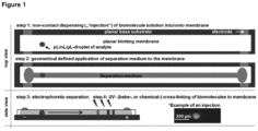
- Procédé de fabrication d'un dispositif de séparation électrophorétique selon l'une quelconque des revendications 1 à 7, dans lequel le milieu de séparation est appliqué sur la surface du matériau d'échafaudage poreux selon une forme géométrique remplissant uniquement des parties du matériau d'échafaudage poreux et définissant un chemin de migration pour un échantillon et pénètre dans le matériau d'échafaudage poreux, dans lequel, de préférence, le milieu de séparation est appliqué sur la surface du matériau d'échafaudage poreux par écriture par semi-contact, distribution sans contact ou distribution par contact.
- Procédé de séparation électrophorétique de biomolécules, comprenant- la fourniture d'un dispositif de séparation électrophorétique, comprenanti. une anode et une cathode,ii. un matériau d'échafaudage poreux, etiii. un milieu de séparation liquide, caractérisé en ce que le milieu de séparation1. est situé à l'intérieur du matériau d'échafaudage poreux,2. est en contact avec la cathode et l'anode, et3. a été appliqué au matériau d'échafaudage poreux de sorte que le milieu de séparation liquide ne remplit que des parties du matériau d'échafaudage poreux et forme un canal d'une largeur de 25 à 1 000 µm définissant un chemin de migration pour un échantillon, dans lequel l'échantillon est entouré par le milieu de séparation, alors que, dans d'autres parties du matériau d'échafaudage poreux, les pores ne sont pas remplis de milieu de séparation liquide, et- un échantillon contenant une biomolécule, dans lequeli. l'échantillon est appliqué sur le matériau d'échafaudage poreux avant l'application du milieu de séparation, ouii. l'échantillon est appliqué sur le milieu de séparation situé à l'intérieur du matériau d'échafaudage poreux, ce qui entraîne l'enceinte de l'échantillon par le milieu de séparation, dans lequel l'emplacement de l'échantillon à l'intérieur du milieu de séparation peut être librement choisi,- l'application d'une tension au milieu de séparation au moyen de l'anode et de la cathode conduisant à la migration des biomolécules à l'intérieur du milieu de séparation.
- Procédé de séparation de biomolécules selon la revendication 9, dans lequel l'échantillon est appliqué par écriture par semi-contact ou distribution sans contact ou distribution par contact.
- Procédé de séparation de biomolécules selon l'une ou plusieurs des revendications 9 à 10, dans lequel l'échantillon comprend des biomolécules sélectionnées dans le groupe comprenant l'ADN, l'ARN, les protéines, les lipides, les glucides et des combinaisons de ceux-ci, et/ou dans lequel le volume de l'échantillon est de 1 pl à 1 000 nl, de préférence de 10 pl à 100 nl, de manière davantage préférée 100 pl à 10 nl, de manière préférée entre toutes 1 nl.
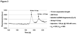
- Procédé de séparation de biomolécules selon une ou plusieurs des revendications 9 à 11, dans lequel une ou plusieurs biomolécules sont visualisées et/ou quantifiées pendant la migration, et/ou dans lequel les biomolécules sont détectées au moyen d'une détection, de préférence sélectionnées dans le groupe comprenant des marqueurs fluorescents, des sondes d'acide nucléique, des anticorps, des aptamères et des molécules qui se lient spécifiquement à la biomolécule à détecter.
- Procédé de séparation de biomolécules selon l'une ou plusieurs des revendications 9 à 12, dans lequel les biomolécules sont immobilisées sur le matériau d'échafaudage poreux ou sur le milieu de séparation lors de l'application d'un stimulus de liaison.
- Procédé de séparation de biomolécules selon une ou plusieurs des revendications 9 à 13, dans lequel un ou plusieurs échantillons sont appliqués à différents canaux de séparation situés à l'intérieur du matériau d'échafaudage poreux pour une analyse parallèle.
- Procédé de séparation de biomolécules selon une ou plusieurs des revendications 9 à 14, dans lequel le milieu de séparation est au moins partiellement recouvert par un fluide non miscible pour empêcher l'évaporation.
Applications Claiming Priority (1)
| Application Number | Priority Date | Filing Date | Title |
|---|---|---|---|
| PCT/EP2017/069456 WO2019024990A1 (fr) | 2017-08-01 | 2017-08-01 | Séparation électrophorétique de biomolécules |
Publications (2)
| Publication Number | Publication Date |
|---|---|
| EP3662276A1 EP3662276A1 (fr) | 2020-06-10 |
| EP3662276B1 true EP3662276B1 (fr) | 2024-07-10 |
Family
ID=59506277
Family Applications (1)
| Application Number | Title | Priority Date | Filing Date |
|---|---|---|---|
| EP17746479.9A Active EP3662276B1 (fr) | 2017-08-01 | 2017-08-01 | Séparation électrophorétique de biomolecules |
Country Status (4)
| Country | Link |
|---|---|
| US (1) | US11313830B2 (fr) |
| EP (1) | EP3662276B1 (fr) |
| CN (1) | CN110998310B (fr) |
| WO (1) | WO2019024990A1 (fr) |
Families Citing this family (1)
| Publication number | Priority date | Publication date | Assignee | Title |
|---|---|---|---|---|
| CN116134308B (zh) * | 2020-05-19 | 2025-05-27 | 10X基因组学有限公司 | 电泳盒和仪器 |
Citations (1)
| Publication number | Priority date | Publication date | Assignee | Title |
|---|---|---|---|---|
| US5637202A (en) * | 1993-10-27 | 1997-06-10 | California Institute Of Technology | Porous electrophoresis sponges |
Family Cites Families (13)
| Publication number | Priority date | Publication date | Assignee | Title |
|---|---|---|---|---|
| JPS5651295B2 (fr) * | 1974-11-15 | 1981-12-04 | ||
| US4992172A (en) * | 1987-09-14 | 1991-02-12 | Gelman Sciences, Inc. | Blotting methods using polyaldehyde activated membranes |
| US5384025A (en) * | 1994-03-07 | 1995-01-24 | Applied Biosystems, Inc. | Notched spacer for slab-gel electrophoresis |
| AU2001236564A1 (en) | 2000-01-28 | 2001-08-07 | Applied Hydrogel Technology Corporation | Detection of biomolecules in gels following electrophoresis |
| AU2001261226A1 (en) * | 2000-05-05 | 2001-11-20 | George Harding | Improved electrophoresis gel support |
| JP2004518949A (ja) * | 2000-11-20 | 2004-06-24 | 20/20 ジーンシステムズ インコーポレイテッド | 生体分子を検出および分析するための方法、装置、アレイ、およびキット |
| US20030032201A1 (en) | 2001-08-10 | 2003-02-13 | Flesher Robert W. | Method and device for electrophoresis and blotting |
| US7192693B2 (en) | 2004-02-24 | 2007-03-20 | University Of Washington | Methods for photopatterning hydrogels |
| DE102005020134A1 (de) * | 2005-04-29 | 2006-11-02 | Becton, Dickinson And Co. | Verfahren und Vorrichtung zur Durchführung eines parallelen und simultanen Mehrfachprozesses der trägerfreien isoelektrischen Fokussierung |
| JP4915527B2 (ja) * | 2007-09-27 | 2012-04-11 | 凸版印刷株式会社 | 電気泳動兼転写用積層体、電気泳動兼転写用チップ、電気泳動兼転写装置、電気泳動兼転写方法、電気泳動兼転写用積層体の製造方法 |
| EP2260297B1 (fr) * | 2008-04-03 | 2018-08-01 | The Regents of The University of California | Système multidimensionnel ex vivo pour la séparation et l isolement de cellules, vésicules, nanoparticules et biomarqueurs |
| US9976984B2 (en) * | 2013-05-10 | 2018-05-22 | The Regents Of The University Of California | Free-standing microfluidic gel electrophoresis devices and methods |
| JP2016109511A (ja) * | 2014-12-04 | 2016-06-20 | シャープ株式会社 | サンプル分離器具およびサンプル分離吸着装置 |
-
2017
- 2017-08-01 EP EP17746479.9A patent/EP3662276B1/fr active Active
- 2017-08-01 CN CN201780093618.9A patent/CN110998310B/zh active Active
- 2017-08-01 US US16/635,643 patent/US11313830B2/en active Active
- 2017-08-01 WO PCT/EP2017/069456 patent/WO2019024990A1/fr not_active Ceased
Patent Citations (1)
| Publication number | Priority date | Publication date | Assignee | Title |
|---|---|---|---|---|
| US5637202A (en) * | 1993-10-27 | 1997-06-10 | California Institute Of Technology | Porous electrophoresis sponges |
Also Published As
| Publication number | Publication date |
|---|---|
| WO2019024990A1 (fr) | 2019-02-07 |
| US11313830B2 (en) | 2022-04-26 |
| EP3662276A1 (fr) | 2020-06-10 |
| US20210123886A1 (en) | 2021-04-29 |
| CN110998310B (zh) | 2023-08-01 |
| CN110998310A (zh) | 2020-04-10 |
Similar Documents
| Publication | Publication Date | Title |
|---|---|---|
| Schwartz et al. | Droplet-based chemistry on a programmable micro-chip | |
| US6660480B2 (en) | Method for analyzing nucleic acids by means of a substrate having a microchannel structure containing immobilized nucleic acid probes | |
| JP3795823B2 (ja) | 電子ピペッタおよび電気泳動バイアスのための補償手段 | |
| US7258837B2 (en) | Microfluidic device and surface decoration process for solid phase affinity binding assays | |
| CN101848757B (zh) | 用于改进的生物测定法的使用电场的方法和设备 | |
| US20090058428A1 (en) | Method and device for monitoring and controlling fluid locomotion | |
| JPH11502618A (ja) | キャピラリー電気泳動装置および方法 | |
| WO2000070080A1 (fr) | Focalisation de microparticules dans des systemes microfluidiques | |
| WO2011079176A2 (fr) | Systèmes microfluidiques et procédés pour réduire l'échange de molécules entre des gouttelettes | |
| US20060207880A1 (en) | Microfluidic devices and methods of using microfluidic devices | |
| US20060210994A1 (en) | Microfluidic systems and methods for using microfluidic devices | |
| CN111569958B (zh) | 通过使用ewod器件进行扩散的分子分离 | |
| EP3662276B1 (fr) | Séparation électrophorétique de biomolecules | |
| US10710079B2 (en) | Electro-kinectic device for species exchange | |
| US20040149568A1 (en) | Method for loading and unloading macro-molecules from microfluidic devices | |
| US20030087290A1 (en) | Bio-affinity porous matrix in microfluidic channels | |
| US20230381778A1 (en) | Devices, systems, and methods related to nucleic acid isolation | |
| KR20150007718A (ko) | 미세구조물을 이용한 표적물질의 존재확인장치 및 이에 의한 확인방법 | |
| KR100762532B1 (ko) | 마이크로칩을 이용한 시료 분석 방법 | |
| JP2007075051A (ja) | 生体サンプル判別用プレート | |
| WO2004039499A2 (fr) | Procede de chargement et dechargement de macromolecules sur et hors de dispositifs microfluidiques | |
| DE102020102389A1 (de) | Verfahren und system zur isolation von molekülfraktionen | |
| Selvaganapathy | Microfabricated components for an integrated microfluidic electroanalysis system | |
| JP2006242612A (ja) | 生体サンプル判別用プレート | |
| JP2005049357A (ja) | 電子ピペッタおよび電気泳動バイアスのための補償手段 |
Legal Events
| Date | Code | Title | Description |
|---|---|---|---|
| STAA | Information on the status of an ep patent application or granted ep patent |
Free format text: STATUS: UNKNOWN |
|
| STAA | Information on the status of an ep patent application or granted ep patent |
Free format text: STATUS: THE INTERNATIONAL PUBLICATION HAS BEEN MADE |
|
| PUAI | Public reference made under article 153(3) epc to a published international application that has entered the european phase |
Free format text: ORIGINAL CODE: 0009012 |
|
| STAA | Information on the status of an ep patent application or granted ep patent |
Free format text: STATUS: REQUEST FOR EXAMINATION WAS MADE |
|
| 17P | Request for examination filed |
Effective date: 20200121 |
|
| AK | Designated contracting states |
Kind code of ref document: A1 Designated state(s): AL AT BE BG CH CY CZ DE DK EE ES FI FR GB GR HR HU IE IS IT LI LT LU LV MC MK MT NL NO PL PT RO RS SE SI SK SM TR |
|
| AX | Request for extension of the european patent |
Extension state: BA ME |
|
| DAV | Request for validation of the european patent (deleted) | ||
| DAX | Request for extension of the european patent (deleted) | ||
| STAA | Information on the status of an ep patent application or granted ep patent |
Free format text: STATUS: EXAMINATION IS IN PROGRESS |
|
| 17Q | First examination report despatched |
Effective date: 20221124 |
|
| GRAP | Despatch of communication of intention to grant a patent |
Free format text: ORIGINAL CODE: EPIDOSNIGR1 |
|
| STAA | Information on the status of an ep patent application or granted ep patent |
Free format text: STATUS: GRANT OF PATENT IS INTENDED |
|
| INTG | Intention to grant announced |
Effective date: 20240221 |
|
| GRAS | Grant fee paid |
Free format text: ORIGINAL CODE: EPIDOSNIGR3 |
|
| GRAA | (expected) grant |
Free format text: ORIGINAL CODE: 0009210 |
|
| STAA | Information on the status of an ep patent application or granted ep patent |
Free format text: STATUS: THE PATENT HAS BEEN GRANTED |
|
| REG | Reference to a national code |
Ref country code: DE Ref legal event code: R081 Ref document number: 602017083184 Country of ref document: DE Owner name: ALBERT-LUDWIGS-UNIVERSITAET FREIBURG, KOERPERS, DE Free format text: FORMER OWNER: ANMELDERANGABEN UNKLAR / UNVOLLSTAENDIG, 80297 MUENCHEN, DE |
|
| AK | Designated contracting states |
Kind code of ref document: B1 Designated state(s): AL AT BE BG CH CY CZ DE DK EE ES FI FR GB GR HR HU IE IS IT LI LT LU LV MC MK MT NL NO PL PT RO RS SE SI SK SM TR |
|
| REG | Reference to a national code |
Ref country code: CH Ref legal event code: EP |
|
| REG | Reference to a national code |
Ref country code: DE Ref legal event code: R081 Ref document number: 602017083184 Country of ref document: DE Owner name: ALBERT-LUDWIGS-UNIVERSITAET FREIBURG, KOERPERS, DE Free format text: FORMER OWNER: ALBERT-LUDWIGS-UNIVERSITAET FREIBURG, 79098 FREIBURG, DE |
|
| REG | Reference to a national code |
Ref country code: DE Ref legal event code: R096 Ref document number: 602017083184 Country of ref document: DE |
|
| REG | Reference to a national code |
Ref country code: LT Ref legal event code: MG9D |
|
| REG | Reference to a national code |
Ref country code: NL Ref legal event code: MP Effective date: 20240710 |
|
| PG25 | Lapsed in a contracting state [announced via postgrant information from national office to epo] |
Ref country code: PT Free format text: LAPSE BECAUSE OF FAILURE TO SUBMIT A TRANSLATION OF THE DESCRIPTION OR TO PAY THE FEE WITHIN THE PRESCRIBED TIME-LIMIT Effective date: 20241111 |
|
| REG | Reference to a national code |
Ref country code: AT Ref legal event code: MK05 Ref document number: 1702456 Country of ref document: AT Kind code of ref document: T Effective date: 20240710 |
|
| PG25 | Lapsed in a contracting state [announced via postgrant information from national office to epo] |
Ref country code: NL Free format text: LAPSE BECAUSE OF FAILURE TO SUBMIT A TRANSLATION OF THE DESCRIPTION OR TO PAY THE FEE WITHIN THE PRESCRIBED TIME-LIMIT Effective date: 20240710 |
|
| PG25 | Lapsed in a contracting state [announced via postgrant information from national office to epo] |
Ref country code: PT Free format text: LAPSE BECAUSE OF FAILURE TO SUBMIT A TRANSLATION OF THE DESCRIPTION OR TO PAY THE FEE WITHIN THE PRESCRIBED TIME-LIMIT Effective date: 20241111 Ref country code: NL Free format text: LAPSE BECAUSE OF FAILURE TO SUBMIT A TRANSLATION OF THE DESCRIPTION OR TO PAY THE FEE WITHIN THE PRESCRIBED TIME-LIMIT Effective date: 20240710 |
|
| PG25 | Lapsed in a contracting state [announced via postgrant information from national office to epo] |
Ref country code: NO Free format text: LAPSE BECAUSE OF FAILURE TO SUBMIT A TRANSLATION OF THE DESCRIPTION OR TO PAY THE FEE WITHIN THE PRESCRIBED TIME-LIMIT Effective date: 20241010 |
|
| PG25 | Lapsed in a contracting state [announced via postgrant information from national office to epo] |
Ref country code: FI Free format text: LAPSE BECAUSE OF FAILURE TO SUBMIT A TRANSLATION OF THE DESCRIPTION OR TO PAY THE FEE WITHIN THE PRESCRIBED TIME-LIMIT Effective date: 20240710 Ref country code: GR Free format text: LAPSE BECAUSE OF FAILURE TO SUBMIT A TRANSLATION OF THE DESCRIPTION OR TO PAY THE FEE WITHIN THE PRESCRIBED TIME-LIMIT Effective date: 20241011 Ref country code: PL Free format text: LAPSE BECAUSE OF FAILURE TO SUBMIT A TRANSLATION OF THE DESCRIPTION OR TO PAY THE FEE WITHIN THE PRESCRIBED TIME-LIMIT Effective date: 20240710 |
|
| PG25 | Lapsed in a contracting state [announced via postgrant information from national office to epo] |
Ref country code: BG Free format text: LAPSE BECAUSE OF FAILURE TO SUBMIT A TRANSLATION OF THE DESCRIPTION OR TO PAY THE FEE WITHIN THE PRESCRIBED TIME-LIMIT Effective date: 20240710 |
|
| PG25 | Lapsed in a contracting state [announced via postgrant information from national office to epo] |
Ref country code: LV Free format text: LAPSE BECAUSE OF FAILURE TO SUBMIT A TRANSLATION OF THE DESCRIPTION OR TO PAY THE FEE WITHIN THE PRESCRIBED TIME-LIMIT Effective date: 20240710 |
|
| PG25 | Lapsed in a contracting state [announced via postgrant information from national office to epo] |
Ref country code: IS Free format text: LAPSE BECAUSE OF FAILURE TO SUBMIT A TRANSLATION OF THE DESCRIPTION OR TO PAY THE FEE WITHIN THE PRESCRIBED TIME-LIMIT Effective date: 20241110 Ref country code: AT Free format text: LAPSE BECAUSE OF FAILURE TO SUBMIT A TRANSLATION OF THE DESCRIPTION OR TO PAY THE FEE WITHIN THE PRESCRIBED TIME-LIMIT Effective date: 20240710 |
|
| PG25 | Lapsed in a contracting state [announced via postgrant information from national office to epo] |
Ref country code: HR Free format text: LAPSE BECAUSE OF FAILURE TO SUBMIT A TRANSLATION OF THE DESCRIPTION OR TO PAY THE FEE WITHIN THE PRESCRIBED TIME-LIMIT Effective date: 20240710 |
|
| PG25 | Lapsed in a contracting state [announced via postgrant information from national office to epo] |
Ref country code: ES Free format text: LAPSE BECAUSE OF FAILURE TO SUBMIT A TRANSLATION OF THE DESCRIPTION OR TO PAY THE FEE WITHIN THE PRESCRIBED TIME-LIMIT Effective date: 20240710 Ref country code: RS Free format text: LAPSE BECAUSE OF FAILURE TO SUBMIT A TRANSLATION OF THE DESCRIPTION OR TO PAY THE FEE WITHIN THE PRESCRIBED TIME-LIMIT Effective date: 20241010 |
|
| PG25 | Lapsed in a contracting state [announced via postgrant information from national office to epo] |
Ref country code: RS Free format text: LAPSE BECAUSE OF FAILURE TO SUBMIT A TRANSLATION OF THE DESCRIPTION OR TO PAY THE FEE WITHIN THE PRESCRIBED TIME-LIMIT Effective date: 20241010 Ref country code: PL Free format text: LAPSE BECAUSE OF FAILURE TO SUBMIT A TRANSLATION OF THE DESCRIPTION OR TO PAY THE FEE WITHIN THE PRESCRIBED TIME-LIMIT Effective date: 20240710 Ref country code: NO Free format text: LAPSE BECAUSE OF FAILURE TO SUBMIT A TRANSLATION OF THE DESCRIPTION OR TO PAY THE FEE WITHIN THE PRESCRIBED TIME-LIMIT Effective date: 20241010 Ref country code: LV Free format text: LAPSE BECAUSE OF FAILURE TO SUBMIT A TRANSLATION OF THE DESCRIPTION OR TO PAY THE FEE WITHIN THE PRESCRIBED TIME-LIMIT Effective date: 20240710 Ref country code: IS Free format text: LAPSE BECAUSE OF FAILURE TO SUBMIT A TRANSLATION OF THE DESCRIPTION OR TO PAY THE FEE WITHIN THE PRESCRIBED TIME-LIMIT Effective date: 20241110 Ref country code: HR Free format text: LAPSE BECAUSE OF FAILURE TO SUBMIT A TRANSLATION OF THE DESCRIPTION OR TO PAY THE FEE WITHIN THE PRESCRIBED TIME-LIMIT Effective date: 20240710 Ref country code: GR Free format text: LAPSE BECAUSE OF FAILURE TO SUBMIT A TRANSLATION OF THE DESCRIPTION OR TO PAY THE FEE WITHIN THE PRESCRIBED TIME-LIMIT Effective date: 20241011 Ref country code: FI Free format text: LAPSE BECAUSE OF FAILURE TO SUBMIT A TRANSLATION OF THE DESCRIPTION OR TO PAY THE FEE WITHIN THE PRESCRIBED TIME-LIMIT Effective date: 20240710 Ref country code: ES Free format text: LAPSE BECAUSE OF FAILURE TO SUBMIT A TRANSLATION OF THE DESCRIPTION OR TO PAY THE FEE WITHIN THE PRESCRIBED TIME-LIMIT Effective date: 20240710 Ref country code: BG Free format text: LAPSE BECAUSE OF FAILURE TO SUBMIT A TRANSLATION OF THE DESCRIPTION OR TO PAY THE FEE WITHIN THE PRESCRIBED TIME-LIMIT Effective date: 20240710 Ref country code: AT Free format text: LAPSE BECAUSE OF FAILURE TO SUBMIT A TRANSLATION OF THE DESCRIPTION OR TO PAY THE FEE WITHIN THE PRESCRIBED TIME-LIMIT Effective date: 20240710 |
|
| REG | Reference to a national code |
Ref country code: DE Ref legal event code: R119 Ref document number: 602017083184 Country of ref document: DE |
|
| REG | Reference to a national code |
Ref country code: CH Ref legal event code: PL |
|
| PG25 | Lapsed in a contracting state [announced via postgrant information from national office to epo] |
Ref country code: RO Free format text: LAPSE BECAUSE OF FAILURE TO SUBMIT A TRANSLATION OF THE DESCRIPTION OR TO PAY THE FEE WITHIN THE PRESCRIBED TIME-LIMIT Effective date: 20240710 Ref country code: DK Free format text: LAPSE BECAUSE OF FAILURE TO SUBMIT A TRANSLATION OF THE DESCRIPTION OR TO PAY THE FEE WITHIN THE PRESCRIBED TIME-LIMIT Effective date: 20240710 Ref country code: SM Free format text: LAPSE BECAUSE OF FAILURE TO SUBMIT A TRANSLATION OF THE DESCRIPTION OR TO PAY THE FEE WITHIN THE PRESCRIBED TIME-LIMIT Effective date: 20240710 |
|
| PG25 | Lapsed in a contracting state [announced via postgrant information from national office to epo] |
Ref country code: LU Free format text: LAPSE BECAUSE OF NON-PAYMENT OF DUE FEES Effective date: 20240801 |
|
| PG25 | Lapsed in a contracting state [announced via postgrant information from national office to epo] |
Ref country code: CH Free format text: LAPSE BECAUSE OF NON-PAYMENT OF DUE FEES Effective date: 20240831 Ref country code: MC Free format text: LAPSE BECAUSE OF FAILURE TO SUBMIT A TRANSLATION OF THE DESCRIPTION OR TO PAY THE FEE WITHIN THE PRESCRIBED TIME-LIMIT Effective date: 20240710 Ref country code: EE Free format text: LAPSE BECAUSE OF FAILURE TO SUBMIT A TRANSLATION OF THE DESCRIPTION OR TO PAY THE FEE WITHIN THE PRESCRIBED TIME-LIMIT Effective date: 20240710 |
|
| PG25 | Lapsed in a contracting state [announced via postgrant information from national office to epo] |
Ref country code: CZ Free format text: LAPSE BECAUSE OF FAILURE TO SUBMIT A TRANSLATION OF THE DESCRIPTION OR TO PAY THE FEE WITHIN THE PRESCRIBED TIME-LIMIT Effective date: 20240710 |
|
| PG25 | Lapsed in a contracting state [announced via postgrant information from national office to epo] |
Ref country code: IT Free format text: LAPSE BECAUSE OF FAILURE TO SUBMIT A TRANSLATION OF THE DESCRIPTION OR TO PAY THE FEE WITHIN THE PRESCRIBED TIME-LIMIT Effective date: 20240710 Ref country code: SK Free format text: LAPSE BECAUSE OF FAILURE TO SUBMIT A TRANSLATION OF THE DESCRIPTION OR TO PAY THE FEE WITHIN THE PRESCRIBED TIME-LIMIT Effective date: 20240710 |
|
| PLBE | No opposition filed within time limit |
Free format text: ORIGINAL CODE: 0009261 |
|
| STAA | Information on the status of an ep patent application or granted ep patent |
Free format text: STATUS: NO OPPOSITION FILED WITHIN TIME LIMIT |
|
| 26N | No opposition filed |
Effective date: 20250411 |
|
| GBPC | Gb: european patent ceased through non-payment of renewal fee |
Effective date: 20241010 |
|
| REG | Reference to a national code |
Ref country code: BE Ref legal event code: MM Effective date: 20240831 |
|
| PG25 | Lapsed in a contracting state [announced via postgrant information from national office to epo] |
Ref country code: DE Free format text: LAPSE BECAUSE OF NON-PAYMENT OF DUE FEES Effective date: 20250301 |
|
| PG25 | Lapsed in a contracting state [announced via postgrant information from national office to epo] |
Ref country code: GB Free format text: LAPSE BECAUSE OF NON-PAYMENT OF DUE FEES Effective date: 20241010 |
|
| PG25 | Lapsed in a contracting state [announced via postgrant information from national office to epo] |
Ref country code: BE Free format text: LAPSE BECAUSE OF NON-PAYMENT OF DUE FEES Effective date: 20240831 |
|
| PG25 | Lapsed in a contracting state [announced via postgrant information from national office to epo] |
Ref country code: FR Free format text: LAPSE BECAUSE OF NON-PAYMENT OF DUE FEES Effective date: 20240910 |
|
| PG25 | Lapsed in a contracting state [announced via postgrant information from national office to epo] |
Ref country code: IE Free format text: LAPSE BECAUSE OF NON-PAYMENT OF DUE FEES Effective date: 20240801 |
|
| PG25 | Lapsed in a contracting state [announced via postgrant information from national office to epo] |
Ref country code: SE Free format text: LAPSE BECAUSE OF FAILURE TO SUBMIT A TRANSLATION OF THE DESCRIPTION OR TO PAY THE FEE WITHIN THE PRESCRIBED TIME-LIMIT Effective date: 20240710 |
|
| PG25 | Lapsed in a contracting state [announced via postgrant information from national office to epo] |
Ref country code: CY Free format text: LAPSE BECAUSE OF FAILURE TO SUBMIT A TRANSLATION OF THE DESCRIPTION OR TO PAY THE FEE WITHIN THE PRESCRIBED TIME-LIMIT; INVALID AB INITIO Effective date: 20170801 |
|
| PG25 | Lapsed in a contracting state [announced via postgrant information from national office to epo] |
Ref country code: HU Free format text: LAPSE BECAUSE OF FAILURE TO SUBMIT A TRANSLATION OF THE DESCRIPTION OR TO PAY THE FEE WITHIN THE PRESCRIBED TIME-LIMIT; INVALID AB INITIO Effective date: 20170801 |