EP3662275B1 - Systèmes et procédés d'évaluation de capteurs de gaz toxiques employant une spectroscopie d'impédance électrochimique - Google Patents
Systèmes et procédés d'évaluation de capteurs de gaz toxiques employant une spectroscopie d'impédance électrochimique Download PDFInfo
- Publication number
- EP3662275B1 EP3662275B1 EP18840535.1A EP18840535A EP3662275B1 EP 3662275 B1 EP3662275 B1 EP 3662275B1 EP 18840535 A EP18840535 A EP 18840535A EP 3662275 B1 EP3662275 B1 EP 3662275B1
- Authority
- EP
- European Patent Office
- Prior art keywords
- toxic gas
- sensor
- electrochemical sensor
- impedances
- electrode
- Prior art date
- Legal status (The legal status is an assumption and is not a legal conclusion. Google has not performed a legal analysis and makes no representation as to the accuracy of the status listed.)
- Active
Links
Images


Classifications
-
- G—PHYSICS
- G01—MEASURING; TESTING
- G01N—INVESTIGATING OR ANALYSING MATERIALS BY DETERMINING THEIR CHEMICAL OR PHYSICAL PROPERTIES
- G01N33/00—Investigating or analysing materials by specific methods not covered by groups G01N1/00 - G01N31/00
- G01N33/0004—Gaseous mixtures, e.g. polluted air
- G01N33/0006—Calibrating gas analysers
-
- G—PHYSICS
- G01—MEASURING; TESTING
- G01N—INVESTIGATING OR ANALYSING MATERIALS BY DETERMINING THEIR CHEMICAL OR PHYSICAL PROPERTIES
- G01N27/00—Investigating or analysing materials by the use of electric, electrochemical, or magnetic means
- G01N27/02—Investigating or analysing materials by the use of electric, electrochemical, or magnetic means by investigating impedance
- G01N27/026—Dielectric impedance spectroscopy
-
- G—PHYSICS
- G01—MEASURING; TESTING
- G01N—INVESTIGATING OR ANALYSING MATERIALS BY DETERMINING THEIR CHEMICAL OR PHYSICAL PROPERTIES
- G01N27/00—Investigating or analysing materials by the use of electric, electrochemical, or magnetic means
- G01N27/26—Investigating or analysing materials by the use of electric, electrochemical, or magnetic means by investigating electrochemical variables; by using electrolysis or electrophoresis
- G01N27/403—Cells and electrode assemblies
- G01N27/404—Cells with anode, cathode and cell electrolyte on the same side of a permeable membrane which separates them from the sample fluid, e.g. Clark-type oxygen sensors
-
- G—PHYSICS
- G01—MEASURING; TESTING
- G01N—INVESTIGATING OR ANALYSING MATERIALS BY DETERMINING THEIR CHEMICAL OR PHYSICAL PROPERTIES
- G01N27/00—Investigating or analysing materials by the use of electric, electrochemical, or magnetic means
- G01N27/26—Investigating or analysing materials by the use of electric, electrochemical, or magnetic means by investigating electrochemical variables; by using electrolysis or electrophoresis
- G01N27/416—Systems
- G01N27/4163—Systems checking the operation of, or calibrating, the measuring apparatus
-
- G—PHYSICS
- G01—MEASURING; TESTING
- G01N—INVESTIGATING OR ANALYSING MATERIALS BY DETERMINING THEIR CHEMICAL OR PHYSICAL PROPERTIES
- G01N33/00—Investigating or analysing materials by specific methods not covered by groups G01N1/00 - G01N31/00
- G01N33/0004—Gaseous mixtures, e.g. polluted air
- G01N33/0009—General constructional details of gas analysers, e.g. portable test equipment
- G01N33/007—Arrangements to check the analyser
Definitions
- the disclosure relates to the art of toxic gas sensors and particularly to efficient calibration and verification of a toxic gas sensor.
- Toxic gas sensors have been widely used in industry to detect and monitor the presence of toxic gases or vapors for safety and environmental purposes. They can provide an early warning of potentially toxic conditions to protect life and property before onset of a hazardous situation.
- gas sensing technologies are used in different types of gas sensors, such as thermal conductivity sensors, infrared (IR) sensors, electrochemical, semiconductor (MOS) sensors and catalytic bead (or pellistor) sensors.
- WO 99/18430 A1 dicloses an electrochemical sensor, in particular, an amperometric gas sensor, is fitted with a test electrode, a reference electrode and a counter electrode.
- the counter electrode is supplied with an input alternating voltage at a given frequency omega, and a test voltage prevailing at the test electrode is evaluated.
- the test voltage is used to monitor a cell constant of the sensor, which represents the surface area of electrode that is available for electrochemical reaction.
- the prevailing test voltages are measured and compared with one another.
- the frequency of the input alternating voltage is selected in such a way that the phase displacement between the input alternating voltage and the test voltage is small or about zero. This makes it possible to monitor the condition or functioning capability of the sensor.
- US 2011/199094 A1 discloses A method, system, and computer program product for age compensation for a gas sensor are provided.
- the method includes determining an impedance spectrum for the gas sensor by an impedance analyzer; determining a set of principle parameters based on the impedance spectrum by a principle parameter identifier; constructing an age compensation model for the gas sensor using the set of principle parameters by an age compensation modeler; and applying the age compensation model to an output of the gas sensor.
- Gas sensor failure detection is also provided.
- Electrochemical sensors are not truly capacitors and resistors, so modeling them as such may introduce some degree of error. In the case of single pulse measurements, these errors are such that aspects of the sensor chemistry may not be represented. Measuring the response of the sensor to a single or very low frequency perturbation may not provide sufficient data to distinguish between the apparent capacitance due to diffusion in the electrolyte and the double layer capacitance at the surface of the electrode/electrolyte interface. Similarly, the electrolyte resistance cannot be distinguished from the electrode polarization resistance.
- the sensitivity may change with temperature and with humidity. Both of these effects may result in a shift in apparent capacitance and resistance when tested with a single, or very low frequency pulse.
- the change in temperature may result in a change only in electrolyte resistance, while a change in humidity primarily may result in a change in polarization resistance; except in cases of extreme low humidity which will affect both polarization and electrolyte resistance.
- Both a drop in humidity and a drop in temperature would result in the sensor losing sensitivity and increasing in response time. Both of these are undesirable.
- prolonged exposure to humidity can cause long term damage to a sensor that could mean it needs to be replaced.
- the current systems evaluate the dynamic behavior of sensors at low frequencies or in response to a single pulse. This appears adequate because the response time of typical electrochemical sensors to their target gas is a few seconds to a few tens of seconds and therefore the sensors are tested at low frequencies, typically less than 10Hz. However, additional information may be obtained about a sensor by studying its performance at higher frequencies.
- the systems and methods of this disclosure enable verification and testing of toxic gas sensors without the need for a target gas with accompanying gas delivery equipment such as a cylinder and tubing.
- the systems and methods for testing toxic gas sensors over a broad range of frequencies facilitates evaluation and diagnosis of mechanisms underlying sensor performance.
- the systems and methods of this disclosure may be incorporated into portable gas sensing equipment for in field diagnostics.
- the present invention relates to a system for evaluating a toxic gas electrochemical sensor
- the system according to the present invention includes a potentiostat circuit electrically connected to the toxic gas electrochemical sensor, a voltage waveform generator connected to the potentiostat circuit and enabled to apply a voltage sine wave at a plurality of selected frequencies to a reference electrode of the toxic gas electrochemical sensor, a current measurement circuit electrically connected to the toxic gas electrochemical sensor for measuring an amplitude and a phase of a current through the toxic gas electrochemical sensor in response to the applied voltage sine wave and a microcontroller electrically connected to the voltage waveform generator and the measurement circuit, wherein the microcontroller controls the voltage waveform generator, receives a corresponding output from the current measurement circuit indicative of the amplitude and the phase of the current through the toxic gas electrochemical sensor at each of the plurality of selected frequencies, and analyzes the output from the current measurement circuit to determine information about a response time of the toxic gas electrochemical sensor, wherein analyzing the output comprises calculating a real impedance and an
- the present disclosure describes a system for evaluating a toxic gas sensor using electrochemical impedance spectroscopy
- the system can include a voltage waveform generator electrically connected to the potentiostat circuit, the voltage wave form generator enabled to input small amplitude voltage sine waves into a reference electrode of the toxic gas sensor, a current measurement circuit electrically connected to the toxic gas sensor, the current measurement circuit enabled to measure amplitude and phase at a counter electrode of the toxic gas sensor in response to the input and a microcontroller electrically connected to the voltage waveform generator and the current measurement circuit, wherein the microcontroller causes the voltage waveform generator to generate a series of voltage sine waves over a frequency range and causes the current measurement circuit to measure the toxic gas sensor response at each frequency, and wherein the microcontroller analyzes the frequency response of the toxic gas sensor.
- the present disclosure describes a system for evaluating a toxic gas sensor using electrochemical impedance spectroscopy
- the system can include a potentiostat circuit electrically connected to the toxic gas sensor, a voltage waveform generator electrically connected to the potentiostat circuit, the voltage wave form generator enabled to input small amplitude voltage sine waves into a reference electrode of the toxic gas sensor, a current measurement circuit electrically connected to the toxic gas sensor, the current measurement circuit enabled to measure amplitude and phase at a counter electrode of the toxic gas sensor in response to the input and a microcontroller electrically connected to the voltage waveform generator and the current measurement circuit, wherein the microcontroller causes the voltage waveform generator to generate a series of voltage sine waves over a frequency range and causes the current measurement circuit to measure the toxic gas sensor response at each frequency and wherein the microcontroller analyzes the frequency response of the toxic gas sensor.
- the present disclosure describes a system for evaluating a toxic gas sensor using electrochemical impedance spectroscopy
- the system can include a galvanostat circuit electrically connected to the toxic gas sensor a current waveform generator electrically connected to the galvanostat circuit, the current wave form generator enabled to input small amplitude current sine waves into a reference electrode of the toxic gas sensor, a voltage measurement circuit electrically connected to the toxic gas sensor, the voltage measurement circuit enabled to measure amplitude and phase at a counter electrode of the toxic gas sensor in response to the input and a microcontroller electrically connected to the current waveform generator and the voltage measurement circuit, wherein the microcontroller causes the current waveform generator to generate a series of current sine waves over a frequency range and causes voltage current measurement circuit to measure the toxic gas sensor response at each frequency and wherein the microcontroller analyzes the frequency response of the toxic gas sensor.
- the present disclosure describes a self-diagnostic toxic gas sensor system
- the system can include a toxic gas sensor, a potentiostat circuit electrically connected to the toxic gas sensor, a voltage waveform generator electrically connected to the potentiostat circuit, the voltage wave form generator enabled to input small amplitude voltage sine waves into a reference electrode of the toxic gas sensor, a current measurement circuit electrically connected to the toxic gas sensor, the current measurement circuit enabled to measure amplitude and phase at a working electrode of the toxic gas sensor in response to the input and a microcontroller electrically connected to the voltage waveform generator and the current measurement circuit, wherein the microcontroller causes the voltage waveform generator to generate a series of voltage sine waves over a frequency range and causes the current measurement circuit to measure the toxic gas sensor response at each frequency and wherein the microcontroller analyzes the frequency response of the toxic gas sensor to diagnose the status of the toxic gas sensor.
- a further embodiment of any of the foregoing embodiments of the present disclosure may include systems wherein an amplitude of the applied voltage sine wave is within a range of 5 mV to 50 mV.
- a further embodiment of any of the foregoing embodiments of the present disclosure may include systems wherein an amplitude of the applied voltage sine wave is within a range in which the toxic gas electrochemical sensor responds in a linear manner.
- a further embodiment of any of the foregoing embodiments of the present disclosure may include systems wherein the plurality of selected frequencies is within a frequency range of 0.1 Hz to 1 MHz.
- a further embodiment of any of the foregoing embodiments of the present disclosure may include systems wherein the plurality of selected frequencies includes at least some sequential frequencies that are spaced in unequal increments from each other.
- the present invention includes systems wherein analyzing the output further comprises comparing a Nyquist plot of the calculated real impedances and the calculated imaginary impedances with a corresponding reference Nyquist plot of reference real impedances and reference imaginary impedances.
- a further embodiment of any of the foregoing embodiments of the present disclosure may include systems wherein the reference real impedances and the reference imaginary impedances are obtained by measuring a newly calibrated toxic gas sensor over a frequency range.
- the present invention includes systems wherein analyzing the output further comprises evaluating differences in a location of features of the Nyquist plot of calculated impedances with a location of features of the reference Nyquist plot of reference impedances.
- a further embodiment of any of the foregoing embodiments of the present disclosure may include systems wherein if a functional change in the toxic gas electrochemical sensor is identified by analyzing the output, then the microcontroller performs at least one of: updating a calibration for the toxic gas electrochemical sensor, updating a calibration for a piece of equipment associated with the toxic gas electrochemical sensor, disabling a piece of equipment associated with the toxic gas electrochemical sensor, and alerting a user.
- a further embodiment of any of the foregoing embodiments of the present disclosure may include systems wherein the toxic gas electrochemical sensor is a three electrode sensor having the reference electrode, a working electrode, and a counter electrode.
- a further embodiment of any of the foregoing embodiments of the present disclosure may include systems wherein the current measurement circuit is connected to the working electrode or the counter electrode.
- a further embodiment of any of the foregoing embodiments of the present disclosure may include systems wherein the toxic gas electrochemical sensor includes either two or four electrode terminals.
- a further embodiment of any of the foregoing embodiments of the present disclosure may include systems wherein the toxic gas electrochemical sensor is a two electrode terminal sensor including a working electrode and the reference electrode, wherein the reference electrode is a combination counter/reference electrode.
- a further embodiment of any of the foregoing embodiments of the present disclosure may include systems wherein the toxic gas electrochemical sensor is a four electrode sensor able to detect at least two different detectable gases, wherein the four electrode sensor comprises the reference electrode, a counter electrode, and at least two working electrodes, wherein each of the at least two working electrodes corresponds to a respective one of the at least two different detectable gases.
- the toxic gas electrochemical sensor is a four electrode sensor able to detect at least two different detectable gases
- the four electrode sensor comprises the reference electrode, a counter electrode, and at least two working electrodes, wherein each of the at least two working electrodes corresponds to a respective one of the at least two different detectable gases.
- a further embodiment of any of the foregoing embodiments of the present disclosure may include systems wherein the current measurement circuit comprises at least two current measurement circuits, wherein each of the at least two current measurement circuits measures current at a respective one of the at least two working electrodes.
- a further embodiment of any of the foregoing embodiments of the present disclosure may include systems wherein information about a functionality of the toxic gas electrochemical sensor comprises information regarding a change in the bulk electrolyte resistance of the toxic gas electrochemical sensor, a change in the freedom of diffusion of ions within the toxic gas electrochemical sensor or a change in the effective polarization impedance of the electrode/electrolyte interface.
- a further embodiment of any of the foregoing embodiments of the present disclosure may include systems wherein information about a functionality of the toxic gas electrochemical sensor comprises information regarding a change in the sensitivity of the toxic gas electrochemical sensor, and non-optionally a change in the response time of the toxic gas electrochemical sensor.
- the present disclosure describes a method for evaluating a toxic gas electrochemical sensor using electrochemical impedance spectroscopy
- the system can include applying a current or a voltage sine wave at a plurality of selected frequencies to a reference electrode of the toxic gas sensor, measuring a voltage or a current response of the toxic gas sensor corresponding to each of the plurality of selected frequencies and analyzing the measured voltage response or the measured current response over the plurality of selected frequencies to determine information about a function of the toxic gas sensor.
- a further embodiment of any of the foregoing embodiments of the present disclosure may include methods wherein analyzing the measured voltage response or the measured current response comprises calculating a real impedance and an imaginary impedance for each of the plurality of selected frequencies resulting in a calculated real impedance and a calculated imaginary impedance.
- a further embodiment of any of the foregoing embodiments of the present disclosure may include methods wherein analyzing the measured voltage response or the measured current response further comprises comparing, for a plurality of key frequencies, the calculated real impedance and the calculated imaginary impedance against a reference real impedance and a reference imaginary impedance.
- the present disclosure describes a system for evaluating a toxic gas electrochemical sensor
- the system can include a galvanostat circuit electrically connected to the toxic gas electrochemical sensor, a current waveform generator connected to the galvanostat circuit and enabled to apply a current sine wave at a plurality of selected frequencies to a reference electrode of the toxic gas electrochemical sensor, a voltage measurement circuit electrically connected to the toxic gas electrochemical sensor for measuring an amplitude and a phase of a voltage across the toxic gas electrochemical sensor in response to the applied current sine wave and a microcontroller electrically connected to the current waveform generator and the measurement circuit, wherein the microcontroller controls the current waveform generator, receives a corresponding output from the voltage measurement circuit indicative of the amplitude and phase of the voltage across the toxic gas electrochemical sensor at each of the plurality of selected frequencies, and analyzes the output to determine information about a functionality of the toxic gas electrochemical sensor.
- a further embodiment of any of the foregoing embodiments of the present disclosure may include systems wherein an amplitude of the applied current sine wave is within a range of 1 nA to 1 mA.
- a further embodiment of any of the foregoing embodiments of the present disclosure may include systems wherein the plurality of selected frequencies is within a frequency range of 0.1 Hz to 1 MHz.
- the present invention includes systems wherein analyzing the output comprises calculating a real impedance and an imaginary impedance corresponding to a current or a voltage measurement at each of the plurality of selected frequencies, and comparing a Nyquist plot of the calculated real impedance and the calculated imaginary impedance with a corresponding reference Nyquist plot of reference real impedances and reference imaginary impedances.
- a further embodiment of any of the foregoing embodiments of the present disclosure may include systems wherein information about a functionality of the toxic gas electrochemical sensor comprises information regarding a change in the bulk electrolyte resistance of the toxic gas electrochemical sensor or a change in the freedom of diffusion of ions within the toxic gas electrochemical sensor.
- a further embodiment of any of the foregoing embodiments of the present disclosure may include systems wherein information about a functionality of the toxic gas electrochemical sensor comprises information regarding a change in the sensitivity of the toxic gas electrochemical sensor, and non-optionally a change in the response time of the toxic gas electrochemical sensor.
- the described system enables the functionality of a sensor to be determined without the need to apply a high pressure cylinder of the target gas to the sensor.
- the system operates by applying specific electrical stimuli to the sensor and measuring the sensor response. This enables sensor functionality checks to be performed without the need for trained personnel to apply a target gas and ensure that the gas delivery equipment is functioning correctly. Thus, any faults in the sensor may be detected without the need for traditional gas testing apparatus.
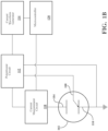
- a block diagram of an embodiment of the test system includes an electrochemical sensor 102 comprising a counter electrode 104, a reference electrode 108 and a working electrode 110, which may be maintained at a stable operating point by a potentiostat circuit 112, as is known in the art.
- a voltage waveform generator 114 may feed small amplitude voltage sine waves into the potentiostat circuit 112 and to the electrochemical sensor 102 over a range of frequencies, such as 1 MHz to 0.1 Hz.
- the current amplitude and phase of the response of the electrochemical sensor 102 to the input sine waves are measured at the working electrode by the current measurement circuit 118.
- the voltage waveform generator 114 is controlled by a microcontroller 120.
- the microcontroller 120 takes the measurements from the current measurement circuit 118 and uses them to calculate the impedance of the electrochemical sensor 102 at various selected frequencies in the input frequency range.
- the amplitude of the input voltage sine waves may be selected to be as large as possible while still maintaining a linear response by the toxic gas electrochemical sensor 102. While the actual voltage amplitude for testing may be specific to the toxic gas electrochemical sensor under test, in embodiments, the input voltage sine waves may have an amplitude in the range of 5 mV to 50 mV.
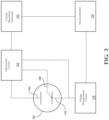
- Fig. 1B illustrates a block diagram of another embodiment of a test system, wherein an electrochemical sensor 102 comprising a counter electrode 104, a reference electrode 108 and a working electrode 110 may be maintained at a stable operating point by a potentiostat circuit 112, as is known in the art.
- a voltage waveform generator 114 is connected to a potentiostat circuit 112 such that voltage sine waves of small amplitude may be injected into the reference electrode 108, such as at frequencies ranging from 1MHz to 0.1Hz.
- the current amplitude and phase response of the electrochemical sensor 102 are measured at the counter electrode 104 and analyzed by a microcontroller 120.
- a voltage waveform generator 114 is connected to a potentiostat circuit 112a such that voltage sine waves of small amplitude may be injected into the reference electrode 108, such as at frequencies ranging from 1MHz to 0.1Hz.
- the current amplitude and phase of the response of the electrochemical sensor 102a to the input sine waves are measured at each working electrode 110a, 110b by a current measurement circuit 118a, 118b.
- the voltage waveform generator 114 is controlled by a microcontroller 120.
- the microcontroller 120 takes the measurements from the current measurement circuits 118a, 118b for each of the working electrodes 110a, 110b and uses them to calculate the impedance of the electrochemical sensor 102a at various frequencies in the input frequency range for the different working electrodes 110a, 110b.
- Fig. 2B illustrates a block diagram of another embodiment of a test system for a two electrode electrochemical sensor 102c with a combination counter/reference electrode 105 and a working electrode 110c which may be maintained at a stable operating point by a potentiostat circuit 112, as is known in the art.
- a voltage waveform generator 114 may feed small amplitude voltage sine waves into the potentiostat circuit 112 over a range of frequencies, such as 1 MHz to 0.1 Hz.
- the current amplitude and phase of the response of the electrochemical sensor 102c to the input sine waves are measured at the working electrode 110c by the current measurement circuit 118.
- the voltage waveform generator 114 is controlled by a microcontroller 120.
- the microcontroller 120 takes the measurements from the current measurement circuit 118 and uses them to calculate the impedance of the electrochemical sensor 102c at various frequencies in the input frequency range.
- Fig. 2C illustrates a block diagram of another embodiment of a test system for a two electrode electrochemical sensor 102c with a combination counter/reference electrode 105 and a working electrode 110c which may be maintained at a stable operating point by a potentiostat circuit 112, as is known in the art.
- a voltage waveform generator 114 may feed small amplitude voltage sine waves into the potentiostat circuit 112 over a range of frequencies, such as 1 MHz to 0.1 Hz.
- the current amplitude and phase of the response of the electrochemical sensor 102c to the input sine waves are measured at the combination counter/reference electrode 105 by the current measurement circuit 118.
- the voltage waveform generator 114 is controlled by a microcontroller 120.
- the microcontroller 120 takes the measurements from the current measurement circuit 118 and uses them to calculate the impedance of the electrochemical sensor 102c at various frequencies in the input frequency range.
- an electrochemical sensor 102 with counter electrode 104, reference electrode 108 and working electrode 110 is maintained at a stable operating point by the galvanostat circuit 122, as is known in the art.
- a current waveform generator 124 is connected to the galvanostat circuit 122 such that small amplitude current sine waves may be fed into the electrochemical sensor 102 at frequencies ranging from 1 MHz to 0.1 Hz.
- the voltage amplitude and phase response of the electrochemical sensor 102 is measured at the counter electrode 104 by the voltage measurement circuit 128.
- the current waveform generator 124 is controlled by the microcontroller 120.
- the microcontroller 120 takes the amplitude and phase response measurements from the voltage measurement circuit 128 and uses them to calculate the impedance of the electrochemical sensor 102 at various frequencies.
- the signal applied to the electrochemical sensor 102 by a signal generator is small enough in amplitude that the electrochemical sensor 102 responds in a linear manner. This allows the electrochemical sensor 102 to quickly recover from the test and resume normal operation. Also, if the electrochemical sensor 102 response becomes non-linear the response may introduce other frequency harmonics into the sensor response making analysis of the electrochemical sensor 102 output much less accurate.
- the microcontroller 120 analyzes the amplitude and phase response of the electrochemical sensor 102 and calculates the real and imaginary impedance of the electrochemical sensor 102 for each of a plurality of selected frequencies in the frequency range of the voltage or current injected into the electrochemical sensor 102 by the waveform generator. Based on the analysis of the amplitude and phase response of the electrochemical sensor 102, the microcontroller 120 may apply algorithms that enable it to determine various parameters representative of the electrochemical sensor's 102 internal chemistry. These parameters may be used to assess the electrochemical sensor's 102 functionality and predict the electrochemical sensor's 102 performance.
- the microcontroller may perform one or more of: provide calibration files for the toxic gas sensor; provide calibration files for a personal protective equipment associated with the toxic gas sensor or a tool associated with the toxic gas sensor; issue an alert to a user of the piece of personal protective equipment or tool; request that the user take some corrective action such as calibrating the sensor; log a discrepancy in performance of the toxic gas sensor; log a potential discrepancy in performance of a tool or piece of protective equipment; shut off a piece of equipment associated with the toxic gas sensor; disable the toxic gas sensor; and the like.
- electrochemical impedance spectroscopy (EIS) spectrum response demonstrate the correlation between electrochemical impedance spectroscopy (EIS) spectrum response and the electrochemical sensor 102 performance.
- EIS electrochemical impedance spectroscopy
- One of the most significant problems affecting electrochemical sensors 102 is long term exposure to low humidity environments; this is particularly true of CO (carbon monoxide) electrochemical sensors 102. Exposure to low humidity environments for long periods of time may result in a decrease of the CO sensor's sensitivity and an increase in the response time.
- a set of CO electrochemical sensors 102 was placed in an environment with humidity of about 40% relative humidity (RH) and allowed to stabilize for 14 days.
- the sensitivity and response time of the electrochemical sensors 102 were measured using traditional measurement techniques based on the application of the target gas, in this case carbon monoxide.
- the EIS spectra of the electrochemical sensors 102 were then measured using a system similar to that illustrated in Fig. 1 .
- the electrochemical sensors 102 were then placed in an environment with humidity of about 10% RH and allowed to stabilize for 2 weeks.
- the sensitivity and response time of the electrochemical sensors 102 were then measured again using traditional measurement techniques based on the application of the target gas, in this case carbon monoxide.
- the EIS spectra of the electrochemical sensors 102 were then measured using the system of Fig. 1 for a second time.
- the response of the sensors was measured by the potentiostat.
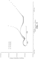
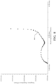
- a Nyquist plot shows impedance measurements as an input waveform is varied in frequency from 0.1 Hz to 1 MHz for an electrochemical sensor 102 at 10% RH and at 40% RH.
- the horizontal axis of Fig. 4 shows real impedance while the vertical access shows imaginary impedance.
- the data on the left shown as diamonds represents measurements that were taken when the electrochemical sensor 102 was at 40% RH while the data on the right, shown as triangles, represent measurements that were taken when the electrochemical sensor 102 was at 10% RH.
- the left most point on the plot for each data set shows that the bulk electrolyte resistance also increased as the humidity decreased as the bulk electrolyte resistance at 40% is approximately half the bulk electrolyte resistance at 10%.
- the rate/freedom of diffusion of ions within the sensor can be seen as the slope of the line on the right side of each plot.
- the line starts from the trough at the end of the circle going up at about a 45 degree slope. It then increases its slope at inflection point 404, indicating a change from a free diffusion system to a bounded diffusion system.
- the 10% RH plot there isn't a clear change in slope, appearing to indicate that the boundary between a free diffusion system and a bounded diffusion system is less clearly defined.
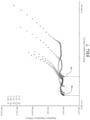
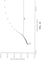
- the Nyquist plot of Fig. 5 shows similar features for impedance measurements as an input waveform is varied in frequency from 0.1 Hz to 1 MHz for a different CO electrochemical sensor 102 at 10% RH (triangles) and at 40% RH (diamonds). Again, analysis of the graph indicates that the electrochemical sensor's 102 impedance increased as the humidity decreased from 40% RH on the left hand side to 10% RH on the right hand side as may be seen in the overall shift in the measurement curve to higher impedances.
- An electrochemical sensor 102 measured in different system embodiments may result in similar response curves.
- a Nyquist plot ( Fig. 6 ) shows impedance measurements as an input waveform is varied in frequency from 0.1 Hz to 1 MHz for the same electrochemical sensor 102 as measured in Fig. 4 but measured using the system of Fig. 2 .
- the graphs show similar features such as the effective polarization impedance of the electrode/electrolyte interface represented by the "diameter" 602 of the response.
- a Nyquist plot shows changes in impedance measurements as an input waveform is varied in frequency from 0.1 Hz to 1 MHz for a CO electrochemical sensor 102 at temperatures ranging from -30° Celsius to +60° Celsius.
- the horizontal axis shows real impedance while the vertical access shows imaginary impedance.
- the sensor demonstrates increased real impedance with decreasing temperature as shown by the increase in the lowest level of real impedance between 702 and 704.
- a Nyquist plot of the measured impedances may be compared to a reference Nyquist plot measured on the same sensor when newly calibrated.
- the measurements for the reference Nyquist plot may be taken when the sensor is new in the factory or on subsequent occasions when the sensor is freshly calibrated.
- the sensor may be calibrated using a reference gas as described elsewhere prior to obtaining measurements for a reference Nyquist plot.
- Changes in the position or size of features such as inflection points, diameter, and/or starting impedance of circles or half circles, and the like on the measured Nyquist plot relative to the reference Nyquist plot may be used to analyze the performance of the electrochemical sensor and identify a change in the sensitivity of the toxic gas electrochemical sensor sensitivity or a change in response time relative to the performance at the time of the reference measurements.
- the measurements of the sensor may be taken more frequently (at smaller frequency intervals) at frequencies surrounding expected features as seen in the reference Nyquist plot.
- the invention includes using the diameter of the half circle formed by a plot of the calculated impedances in the Nyquist plot to determine a change in the sensor response time.
- the sensor is measured at a different temperature for the measured Nyquist plot compared to the temperature at which the reference Nyquist plot was measured, compensation for the shift in response with temperature, which is fairly consistent from sensor to sensor, may be applied. This may enable improved analysis of response differences related to humidity or sensor poisoning.
- the system and methods of this disclosure may be used to evaluate the response of many different types of toxic gas electrochemical sensors 102. There may be differences in the response shape and levels for electrochemical sensors 102 sensitive to different types of toxic gases.
- Figs. 8-10 show Nyquist plots illustrating changes in impedance measurements as an input waveform is varied in frequency from 0.1 Hz to 1 MHz for electrochemical sensors 102 sensitive to different types of toxic gases. While measurements of an oxygen (O2) electrochemical sensor 102 ( Fig. 8 ) show a similar shape to the previous CO electrochemical sensors 102 measurements, the O2 electrochemical sensor has higher impedances and a more pronounced inflection point 804. Measurements of a hydrogen sulfide (H2S) electrochemical sensor 102, as shown in Fig.
- H2S hydrogen sulfide
- the methods and systems described herein may be deployed in part or in whole through a machine that executes computer software, program codes, and/or instructions on a processor.
- the processor may be part of a server, client, network infrastructure, mobile computing platform, stationary computing platform, or other computing platform.
- a processor may be any kind of computational or processing device capable of executing program instructions, codes, binary instructions and the like.
- the processor may be or include a signal processor, digital processor, embedded processor, microprocessor or any variant such as a co-processor (math co-processor, graphic co-processor, communication co-processor and the like) and the like that may directly or indirectly facilitate execution of program code or program instructions stored thereon.
- the processor may enable execution of multiple programs, threads, and codes.
- the threads may be executed simultaneously to enhance the performance of the processor and to facilitate simultaneous operations of the application.
- methods, program codes, program instructions and the like described herein may be implemented in one or more thread.
- the thread may spawn other threads that may have assigned priorities associated with them; the processor may execute these threads based on priority or any other order based on instructions provided in the program code.
- the processor may include memory that stores methods, codes, instructions and programs as described herein and elsewhere.
- the processor may access a storage medium through an interface that may store methods, codes, and instructions as described herein and elsewhere.
- the storage medium associated with the processor for storing methods, programs, codes, program instructions or other type of instructions capable of being executed by the computing or processing device may include but may not be limited to one or more of a CD-ROM, DVD, memory, hard disk, flash drive, RAM, ROM, cache and the like.
- a processor may include one or more cores that may enhance speed and performance of a multiprocessor.
- the process may be a dual core processor, quad core processors, other chip-level multiprocessor and the like that combine two or more independent cores (called a die).
- the methods and systems described herein may be deployed in part or in whole through a machine that executes computer software on a server, client, firewall, gateway, hub, router, or other such computer and/or networking hardware.
- the software program may be associated with a server that may include a file server, print server, domain server, internet server, intranet server and other variants such as secondary server, host server, distributed server and the like.
- the server may include one or more of memories, processors, computer readable transitory and/or non-transitory media, storage media, ports (physical and virtual), communication devices, and interfaces capable of accessing other servers, clients, machines, and devices through a wired or a wireless medium, and the like.
- the methods, programs or codes as described herein and elsewhere may be executed by the server.
- other devices required for execution of methods as described in this application may be considered as a part of the infrastructure associated with the server.
- the server may provide an interface to other devices including, without limitation, clients, other servers, printers, database servers, print servers, file servers, communication servers, distributed servers and the like. Additionally, this coupling and/or connection may facilitate remote execution of program across the network. The networking of some or all of these devices may facilitate parallel processing of a program or method at one or more location without deviating from the scope of the disclosure.
- all the devices attached to the server through an interface may include at least one storage medium capable of storing methods, programs, code and/or instructions.
- a central repository may provide program instructions to be executed on different devices. In this implementation, the remote repository may act as a storage medium for program code, instructions, and programs.
- the software program may be associated with a client that may include a file client, print client, domain client, internet client, intranet client and other variants such as secondary client, host client, distributed client and the like.
- the client may include one or more of memories, processors, computer readable transitory and/or non-transitory media, storage media, ports (physical and virtual), communication devices, and interfaces capable of accessing other clients, servers, machines, and devices through a wired or a wireless medium, and the like.
- the methods, programs or codes as described herein and elsewhere may be executed by the client.
- other devices required for execution of methods as described in this application may be considered as a part of the infrastructure associated with the client.
- the client may provide an interface to other devices including, without limitation, servers, other clients, printers, database servers, print servers, file servers, communication servers, distributed servers and the like. Additionally, this coupling and/or connection may facilitate remote execution of program across the network. The networking of some or all of these devices may facilitate parallel processing of a program or method at one or more location without deviating from the scope of the disclosure.
- all the devices attached to the client through an interface may include at least one storage medium capable of storing methods, programs, applications, code and/or instructions.
- a central repository may provide program instructions to be executed on different devices.
- the remote repository may act as a storage medium for program code, instructions, and programs.
- the methods and systems described herein may be deployed in part or in whole through network infrastructures.
- the network infrastructure may include elements such as computing devices, servers, routers, hubs, firewalls, clients, personal computers, communication devices, routing devices and other active and passive devices, modules and/or components as known in the art.
- the computing and/or non-computing device(s) associated with the network infrastructure may include, apart from other components, a storage medium such as flash memory, buffer, stack, RAM, ROM and the like.
- the processes, methods, program codes, instructions described herein and elsewhere may be executed by one or more of the network infrastructural elements.
- the methods, program codes, and instructions described herein and elsewhere may be implemented on a cellular network having multiple cells.
- the cellular network may either be frequency division multiple access (FDMA) network or code division multiple access (CDMA) network.
- FDMA frequency division multiple access
- CDMA code division multiple access
- the cellular network may include mobile devices, cell sites, base stations, repeaters, antennas, towers, and the like.
- the mobile devices may include navigation devices, cell phones, mobile phones, mobile personal digital assistants, laptops, palmtops, netbooks, pagers, electronic books readers, music players and the like. These devices may include, apart from other components, a storage medium such as a flash memory, buffer, RAM, ROM and one or more computing devices.
- the computing devices associated with mobile devices may be enabled to execute program codes, methods, and instructions stored thereon. Alternatively, the mobile devices may be configured to execute instructions in collaboration with other devices.
- the mobile devices may communicate with base stations interfaced with servers and configured to execute program codes.
- the mobile devices may communicate on a peer to peer network, mesh network, or other communications network.
- the program code may be stored on the storage medium associated with the server and executed by a computing device embedded within the server.
- the base station may include a computing device and a storage medium.
- the storage device may store program codes and instructions executed by the computing devices associated with the base station.
- the computer software, program codes, and/or instructions may be stored and/or accessed on machine readable transitory and/or non-transitory media that may include: computer components, devices, and recording media that retain digital data used for computing for some interval of time; semiconductor storage known as random access memory (RAM); mass storage typically for more permanent storage, such as optical discs, forms of magnetic storage like hard disks, tapes, drums, cards and other types; processor registers, cache memory, volatile memory, non-volatile memory; optical storage such as CD, DVD; removable media such as flash memory (e.g.
- RAM random access memory
- mass storage typically for more permanent storage, such as optical discs, forms of magnetic storage like hard disks, tapes, drums, cards and other types
- processor registers cache memory, volatile memory, non-volatile memory
- optical storage such as CD, DVD
- removable media such as flash memory (e.g.
- USB sticks or keys floppy disks, magnetic tape, paper tape, punch cards, standalone RAM disks, Zip drives, removable mass storage, off-line, and the like; other computer memory such as dynamic memory, static memory, read/write storage, mutable storage, read only, random access, sequential access, location addressable, file addressable, content addressable, network attached storage, storage area network, bar codes, magnetic ink, and the like.
- the methods and systems described herein may transform physical and/or or intangible items from one state to another.
- the methods and systems described herein may also transform data representing physical and/or intangible items from one state to another.
- machines may include, but may not be limited to, personal digital assistants, laptops, personal computers, mobile phones, other handheld computing devices, medical equipment, wired or wireless communication devices, transducers, chips, calculators, satellites, tablet PCs, electronic books, gadgets, electronic devices, devices having artificial intelligence, computing devices, networking equipment, servers, routers and the like.
- the elements depicted in the flow chart and block diagrams or any other logical component may be implemented on a machine capable of executing program instructions.
- the computer executable code may be created using a structured programming language such as C, an object oriented programming language such as C++, or any other high-level or low-level programming language (including assembly languages, hardware description languages, and database programming languages and technologies) that may be stored, compiled or interpreted to run on one of the above devices, as well as heterogeneous combinations of processors, processor architectures, or combinations of different hardware and software, or any other machine capable of executing program instructions.
- a structured programming language such as C
- an object oriented programming language such as C++
- any other high-level or low-level programming language including assembly languages, hardware description languages, and database programming languages and technologies
Landscapes
- Chemical & Material Sciences (AREA)
- Life Sciences & Earth Sciences (AREA)
- Health & Medical Sciences (AREA)
- Physics & Mathematics (AREA)
- Analytical Chemistry (AREA)
- General Health & Medical Sciences (AREA)
- Pathology (AREA)
- Immunology (AREA)
- General Physics & Mathematics (AREA)
- Biochemistry (AREA)
- Engineering & Computer Science (AREA)
- Chemical Kinetics & Catalysis (AREA)
- Electrochemistry (AREA)
- Food Science & Technology (AREA)
- Combustion & Propulsion (AREA)
- Medicinal Chemistry (AREA)
- Molecular Biology (AREA)
- Spectroscopy & Molecular Physics (AREA)
- Investigating Or Analyzing Materials By The Use Of Electric Means (AREA)
Claims (13)
- Système d'évaluation d'un capteur électrochimique de gaz toxique (102), le système comprenant :un circuit de potentiostat (112) connecté électriquement au capteur électrochimique de gaz toxique ;un générateur de forme d'onde de tension (114) connecté au circuit de potentiostat (112) et validé pour appliquer une onde sinusoïdale de tension à une pluralité de fréquences sélectionnées à une électrode de référence (108) du capteur électrochimique de gaz toxique (102) ;un circuit de mesure de courant (118) connecté électriquement au capteur électrochimique de gaz toxique (102) pour mesurer une amplitude et une phase d'un courant à travers le capteur électrochimique de gaz toxique (102) en réponse à l'onde sinusoïdale de tension appliquée ; etun microcontrôleur (120) connecté électriquement au générateur de forme d'onde de tension (114) et au circuit de mesure de courant (118), dans lequel le microcontrôleur (120) contrôle le générateur de forme d'onde de tension (114), reçoit une sortie correspondante du circuit de mesure de courant (118) indicative de l'amplitude et de la phase du courant à travers le capteur électrochimique de gaz toxique (102) à chacune de la pluralité de fréquences sélectionnées, et caractérisé en ce que le microcontrôleur (120) analyse la sortie du circuit de mesure de courant (118) afin de déterminer des informations concernant un temps de réponse du capteur électrochimique de gaz toxique (102),dans lequel analyser la sortie comprend calculer une impédance réelle et une impédance imaginaire correspondant à une mesure de courant à chacune de la pluralité de fréquences sélectionnées résultant en des impédances réelles calculées et en des impédances imaginaires calculées, et dans lequel analyser la sortie comprend en outre comparer un diagramme de Nyquist des impédances réelles calculées et des impédances imaginaires calculées à un diagramme de Nyquist de référence correspondant d'impédances réelles de référence et d'impédances imaginaires de référence,dans lequel la comparaison du diagramme de Nyquist au diagramme de Nyquist de référence correspondant comprend évaluer des différences dans un emplacement d'une ou plusieurs caractéristiques du diagramme de Nyquist avec un emplacement d'une ou plusieurs caractéristiques correspondantes du diagramme de Nyquist de référence, les caractéristiques correspondantes comprenant un diamètre d'un demi-cercle formé par un diagramme des impédances de référence dans le diagramme de Nyquist de référence,dans lequel si un diamètre d'un demi-cercle formé par un diagramme des impédances calculées dans le diagramme Nyquist est plus grand que le diamètre du demi-cercle formé par le diagramme des impédances de référence dans le diagramme de Nyquist de référence, le microcontrôleur détermine qu'une impédance de polarisation effective du capteur électrochimique de gaz toxique a augmenté et que le temps de réponse a augmenté.
- Système selon la revendication 1, dans lequel une amplitude de l'onde sinusoïdale de tension appliquée est dans une plage de 5 mV à 50 mV.
- Système selon la revendication 1, dans lequel une amplitude de l'onde sinusoïdale de tension appliquée est dans une plage dans laquelle le capteur électrochimique de gaz toxique (102) répond de manière linéaire.
- Système selon la revendication 1, dans lequel la pluralité de fréquences sélectionnées est dans une plage de fréquences de 0,1 Hz à 1 MHz.
- Système selon la revendication 4, dans lequel la pluralité de fréquences sélectionnées comprend au moins certaines fréquences séquentielles qui sont espacées les unes des autres en incréments inégaux.
- Système selon la revendication 1, dans lequel les impédances réelles de référence et les impédances imaginaires de référence sont obtenues en mesurant un capteur de gaz toxique nouvellement étalonné (102) sur une plage de fréquences.
- Système selon la revendication 1, dans lequel analyser la sortie comprend en outre évaluer des différences dans un emplacement de caractéristiques du diagramme Nyquist d'impédances calculées avec un emplacement de caractéristiques du diagramme Nyquist de référence d'impédances de référence.
- Système selon la revendication 1, dans lequel si un changement fonctionnel dans le capteur électrochimique de gaz toxique (102) est identifié en analysant la sortie, alors le microcontrôleur (120) effectue au moins l'un d'entre : actualiser un étalonnage du capteur électrochimique de gaz toxique (102), actualiser un étalonnage d'une pièce d'équipement associée au capteur électrochimique de gaz toxique (102), invalider une pièce d'équipement associée au capteur électrochimique de gaz toxique (102), et alerter un utilisateur.
- Système selon la revendication 1, dans lequel le capteur électrochimique de gaz toxique (102) est l'un d'entre un capteur de monoxyde de carbone, un capteur électrochimique d'ammoniac, un capteur de sulfure d'hydrogène et un capteur d'oxygène.
- Système selon la revendication 1, dans lequel le capteur électrochimique de gaz toxique (102) est un capteur à trois électrodes ayant l'électrode de référence (108), une électrode de travail (110) et une contre-électrode (104).
- Système selon la revendication 10, dans lequel le circuit de mesure de courant est connecté à l'électrode de travail (110) ou à la contre-électrode (104).
- Système selon la revendication 1, dans lequel le capteur électrochimique de gaz toxique (102) comprend soit deux soit quatre bornes d'électrodes.
- Système selon la revendication 1, dans lequel le capteur électrochimique de gaz toxique (102) est un capteur à deux bornes d'électrodes comprenant une électrode de travail (110) et l'électrode de référence (108), dans lequel l'électrode de référence (108) est une combinaison de contre-électrode/électrode de référence.
Applications Claiming Priority (3)
| Application Number | Priority Date | Filing Date | Title |
|---|---|---|---|
| US201762540733P | 2017-08-03 | 2017-08-03 | |
| US15/791,557 US11079363B2 (en) | 2017-08-03 | 2017-10-24 | Systems and methods for evaluating toxic gas sensors using electrochemical impedance spectroscopy |
| PCT/US2018/043093 WO2019027701A1 (fr) | 2017-08-03 | 2018-07-20 | Systèmes et procédés d'évaluation de capteurs de gaz toxiques employant une spectroscopie d'impédance électrochimique |
Publications (4)
| Publication Number | Publication Date |
|---|---|
| EP3662275A1 EP3662275A1 (fr) | 2020-06-10 |
| EP3662275A4 EP3662275A4 (fr) | 2021-05-05 |
| EP3662275B1 true EP3662275B1 (fr) | 2025-06-11 |
| EP3662275C0 EP3662275C0 (fr) | 2025-06-11 |
Family
ID=65231560
Family Applications (1)
| Application Number | Title | Priority Date | Filing Date |
|---|---|---|---|
| EP18840535.1A Active EP3662275B1 (fr) | 2017-08-03 | 2018-07-20 | Systèmes et procédés d'évaluation de capteurs de gaz toxiques employant une spectroscopie d'impédance électrochimique |
Country Status (7)
| Country | Link |
|---|---|
| US (1) | US11079363B2 (fr) |
| EP (1) | EP3662275B1 (fr) |
| CN (1) | CN110573869B (fr) |
| CA (1) | CA3056670A1 (fr) |
| ES (1) | ES3035087T3 (fr) |
| PL (1) | PL3662275T3 (fr) |
| WO (1) | WO2019027701A1 (fr) |
Families Citing this family (23)
| Publication number | Priority date | Publication date | Assignee | Title |
|---|---|---|---|---|
| US11079363B2 (en) | 2017-08-03 | 2021-08-03 | Industrial Scientific Corporation | Systems and methods for evaluating toxic gas sensors using electrochemical impedance spectroscopy |
| EP3735583A4 (fr) | 2018-01-22 | 2021-10-27 | Insyte Systems, Inc. | Capteur à faible impédance pour matériaux à faible densité |
| CN113597550A (zh) * | 2019-03-20 | 2021-11-02 | 京瓷株式会社 | 气体检测系统 |
| JP7252921B2 (ja) * | 2019-09-13 | 2023-04-05 | 日本特殊陶業株式会社 | ガスセンサ制御装置、ガスセンサ装置及び内燃機関制御装置 |
| CN110849947B (zh) * | 2019-11-20 | 2022-08-09 | 齐齐哈尔大学 | 水果变质检测系统及其建造方法及检测方法 |
| CN111398377A (zh) * | 2020-04-16 | 2020-07-10 | 北方工业大学 | 轨道交通车站气体环境监测系统及方法 |
| US11760170B2 (en) | 2020-08-20 | 2023-09-19 | Denso International America, Inc. | Olfaction sensor preservation systems and methods |
| US11813926B2 (en) | 2020-08-20 | 2023-11-14 | Denso International America, Inc. | Binding agent and olfaction sensor |
| US11881093B2 (en) | 2020-08-20 | 2024-01-23 | Denso International America, Inc. | Systems and methods for identifying smoking in vehicles |
| US12377711B2 (en) | 2020-08-20 | 2025-08-05 | Denso International America, Inc. | Vehicle feature control systems and methods based on smoking |
| US12017506B2 (en) | 2020-08-20 | 2024-06-25 | Denso International America, Inc. | Passenger cabin air control systems and methods |
| US11932080B2 (en) | 2020-08-20 | 2024-03-19 | Denso International America, Inc. | Diagnostic and recirculation control systems and methods |
| US11636870B2 (en) | 2020-08-20 | 2023-04-25 | Denso International America, Inc. | Smoking cessation systems and methods |
| US12269315B2 (en) | 2020-08-20 | 2025-04-08 | Denso International America, Inc. | Systems and methods for measuring and managing odor brought into rental vehicles |
| US11828210B2 (en) | 2020-08-20 | 2023-11-28 | Denso International America, Inc. | Diagnostic systems and methods of vehicles using olfaction |
| US12251991B2 (en) | 2020-08-20 | 2025-03-18 | Denso International America, Inc. | Humidity control for olfaction sensors |
| US11760169B2 (en) | 2020-08-20 | 2023-09-19 | Denso International America, Inc. | Particulate control systems and methods for olfaction sensors |
| KR102757479B1 (ko) * | 2020-11-19 | 2025-01-20 | 주식회사 엘지에너지솔루션 | 배터리 진단 장치 및 방법 |
| CN112986339B (zh) * | 2020-12-04 | 2022-04-05 | 西安交通大学 | 一种基于交流阻抗的半导体气体传感器测量方法 |
| US20230375492A1 (en) * | 2022-02-09 | 2023-11-23 | Purdue Research Foundation | Methods and apparatus for sensing volatile organic compounds and gases released from electrochemical cells |
| WO2024005837A1 (fr) * | 2022-07-01 | 2024-01-04 | Brewer Science, Inc. | Limitation de courant différentiel pour extension de durée de vie de capteur de voltampérométrie |
| EP4695604A1 (fr) * | 2023-04-14 | 2026-02-18 | The Regents Of The University Of California | Procédés et systèmes d'interrogation de capteurs électrochimiques |
| US20250137955A1 (en) * | 2023-10-26 | 2025-05-01 | Taiwan Semiconductor Manufacturing Company Ltd. | Environment detection apparatus |
Family Cites Families (20)
| Publication number | Priority date | Publication date | Assignee | Title |
|---|---|---|---|---|
| DE4136779A1 (de) * | 1991-11-08 | 1993-05-13 | Bayer Ag | Vorrichtung zum simultanen nachweis verschiedener gaskomponenten |
| DE19622931C2 (de) * | 1996-06-07 | 2001-02-22 | Draegerwerk Ag | Elektrochemischer Mehrgassensor |
| DE19743979A1 (de) | 1997-10-06 | 1999-04-08 | Conducta Endress & Hauser | Verfahren zum Betreiben eines elektrochemischen Sensors sowie elektrische Schaltung für einen elektrochemischen Sensor |
| US6134461A (en) * | 1998-03-04 | 2000-10-17 | E. Heller & Company | Electrochemical analyte |
| AU5500499A (en) | 1998-09-09 | 2000-03-27 | Cominco Ltd. | Apparatus for monitoring the operability of an electrochemical sensor |
| US6428684B1 (en) | 2000-08-02 | 2002-08-06 | Industrial Scientific Corporation | Method and apparatus for diagnosing the condition of a gas sensor |
| US7413645B2 (en) | 2004-05-05 | 2008-08-19 | Mine Safety Appliances Company | Devices, systems and methods for testing gas sensors and correcting gas sensor output |
| US8114268B2 (en) * | 2005-12-30 | 2012-02-14 | Medtronic Minimed, Inc. | Method and system for remedying sensor malfunctions detected by electrochemical impedance spectroscopy |
| US9046463B1 (en) * | 2006-04-21 | 2015-06-02 | University Of Washington | Method for conducting nonlinear electrochemical impedance spectroscopy |
| US7751864B2 (en) | 2007-03-01 | 2010-07-06 | Roche Diagnostics Operations, Inc. | System and method for operating an electrochemical analyte sensor |
| US8603307B2 (en) | 2007-05-25 | 2013-12-10 | Thermo Fisher Scientific, Inc. | Self-diagnostic sensor system |
| US20110199094A1 (en) * | 2010-02-16 | 2011-08-18 | Hamilton Sundstrand Corporation | Gas Sensor Age Compensation and Failure Detection |
| US20130060106A1 (en) * | 2011-09-06 | 2013-03-07 | Medtronic Minimed, Inc. | Optical sensing systems and methods |
| US9408567B2 (en) * | 2012-06-08 | 2016-08-09 | Medtronic Minimed, Inc. | Application of electrochemical impedance spectroscopy in sensor systems, devices, and related methods |
| US9581564B2 (en) | 2013-10-16 | 2017-02-28 | Emisense Technologies, Llc | Electrochemical sensing using voltage-current time differential |
| CN105026922B (zh) * | 2014-02-14 | 2018-04-24 | 罗斯蒙特分析公司 | 固态的气体检测传感器的诊断 |
| US9632059B2 (en) | 2015-09-03 | 2017-04-25 | Ashwin-Ushas Corporation, Inc. | Potentiostat/galvanostat with digital interface |
| US20170181672A1 (en) | 2015-12-28 | 2017-06-29 | Medtronic Minimed, Inc. | Sensor systems, devices, and methods for continuous glucose monitoring |
| US20170184527A1 (en) * | 2015-12-28 | 2017-06-29 | Medtronic Minimed, Inc. | Sensor systems, devices, and methods for continuous glucose monitoring |
| US11079363B2 (en) | 2017-08-03 | 2021-08-03 | Industrial Scientific Corporation | Systems and methods for evaluating toxic gas sensors using electrochemical impedance spectroscopy |
-
2017
- 2017-10-24 US US15/791,557 patent/US11079363B2/en active Active
-
2018
- 2018-07-20 EP EP18840535.1A patent/EP3662275B1/fr active Active
- 2018-07-20 CA CA3056670A patent/CA3056670A1/fr active Pending
- 2018-07-20 CN CN201880030034.1A patent/CN110573869B/zh active Active
- 2018-07-20 WO PCT/US2018/043093 patent/WO2019027701A1/fr not_active Ceased
- 2018-07-20 PL PL18840535.1T patent/PL3662275T3/pl unknown
- 2018-07-20 ES ES18840535T patent/ES3035087T3/es active Active
Non-Patent Citations (1)
| Title |
|---|
| ANONYMOUS: "Basics of EIS: Electrochemical Research-Impedance Gamry Instruments", 25 May 2015 (2015-05-25), pages 1 - 35, XP093232989, Retrieved from the Internet <URL:https://www.gamry.com/application-notes/EIS/basics-of-electrochemical-impedance-spectroscopy/> [retrieved on 20241210] * |
Also Published As
| Publication number | Publication date |
|---|---|
| ES3035087T3 (en) | 2025-08-28 |
| EP3662275A1 (fr) | 2020-06-10 |
| CN110573869B (zh) | 2023-02-21 |
| US20190041371A1 (en) | 2019-02-07 |
| US11079363B2 (en) | 2021-08-03 |
| CN110573869A (zh) | 2019-12-13 |
| EP3662275C0 (fr) | 2025-06-11 |
| WO2019027701A1 (fr) | 2019-02-07 |
| PL3662275T3 (pl) | 2025-09-22 |
| CA3056670A1 (fr) | 2019-02-07 |
| EP3662275A4 (fr) | 2021-05-05 |
Similar Documents
| Publication | Publication Date | Title |
|---|---|---|
| EP3662275B1 (fr) | Systèmes et procédés d'évaluation de capteurs de gaz toxiques employant une spectroscopie d'impédance électrochimique | |
| US12188915B2 (en) | Determination of sensor operational status via sensor interrogation | |
| Fasasi et al. | Benchmarking performance metrics of methane monitoring technologies in simulated environments | |
| CN118425098B (zh) | 一种分布式激光甲烷检测方法及系统 | |
| Chen et al. | Status self-validation of sensor arrays using gray forecasting model and bootstrap method | |
| EP2365322A1 (fr) | Compensation d'âge de capteur de gaz et détection de fautes | |
| JP2022536720A (ja) | 毛細管制限型のセンサへの問い合わせ | |
| US11994935B2 (en) | Apparatus and method for predicting remaining lifetime of environment data collection sensor in livestock house | |
| Leite et al. | Embedded intelligence of end devices with MOS sensors for CH 4 detection | |
| CN115718177A (zh) | 用于整合多个化学传感器数据以检测未测化合物的系统 | |
| Dmitrzak et al. | Identification of defected sensors in an array of amperometric gas sensors | |
| EP4242647A1 (fr) | Dispositif et procédé pour déterminer la concentration d'un gaz cible dans une application mobile | |
| CN111044571B (zh) | 用于检测气体向气体传感器进入的限制的设备和方法 | |
| Vergara et al. | Gas sensor drift mitigation using classifier ensembles | |
| HK1161645A (en) | Gas sensor age compensation and failure detection |
Legal Events
| Date | Code | Title | Description |
|---|---|---|---|
| STAA | Information on the status of an ep patent application or granted ep patent |
Free format text: STATUS: THE INTERNATIONAL PUBLICATION HAS BEEN MADE |
|
| PUAI | Public reference made under article 153(3) epc to a published international application that has entered the european phase |
Free format text: ORIGINAL CODE: 0009012 |
|
| STAA | Information on the status of an ep patent application or granted ep patent |
Free format text: STATUS: REQUEST FOR EXAMINATION WAS MADE |
|
| 17P | Request for examination filed |
Effective date: 20191016 |
|
| AK | Designated contracting states |
Kind code of ref document: A1 Designated state(s): AL AT BE BG CH CY CZ DE DK EE ES FI FR GB GR HR HU IE IS IT LI LT LU LV MC MK MT NL NO PL PT RO RS SE SI SK SM TR |
|
| AX | Request for extension of the european patent |
Extension state: BA ME |
|
| DAV | Request for validation of the european patent (deleted) | ||
| DAX | Request for extension of the european patent (deleted) | ||
| REG | Reference to a national code |
Ref legal event code: R079 Free format text: PREVIOUS MAIN CLASS: G01N0027407000 Ref country code: DE Ref legal event code: R079 Ref document number: 602018082562 Country of ref document: DE Free format text: PREVIOUS MAIN CLASS: G01N0027407000 Ipc: G01N0027020000 |
|
| A4 | Supplementary search report drawn up and despatched |
Effective date: 20210409 |
|
| RIC1 | Information provided on ipc code assigned before grant |
Ipc: G01N 27/02 20060101AFI20210401BHEP Ipc: G01N 33/00 20060101ALI20210401BHEP |
|
| STAA | Information on the status of an ep patent application or granted ep patent |
Free format text: STATUS: EXAMINATION IS IN PROGRESS |
|
| 17Q | First examination report despatched |
Effective date: 20230531 |
|
| P01 | Opt-out of the competence of the unified patent court (upc) registered |
Effective date: 20230530 |
|
| GRAP | Despatch of communication of intention to grant a patent |
Free format text: ORIGINAL CODE: EPIDOSNIGR1 |
|
| STAA | Information on the status of an ep patent application or granted ep patent |
Free format text: STATUS: GRANT OF PATENT IS INTENDED |
|
| INTG | Intention to grant announced |
Effective date: 20250103 |
|
| GRAS | Grant fee paid |
Free format text: ORIGINAL CODE: EPIDOSNIGR3 |
|
| GRAA | (expected) grant |
Free format text: ORIGINAL CODE: 0009210 |
|
| STAA | Information on the status of an ep patent application or granted ep patent |
Free format text: STATUS: THE PATENT HAS BEEN GRANTED |
|
| AK | Designated contracting states |
Kind code of ref document: B1 Designated state(s): AL AT BE BG CH CY CZ DE DK EE ES FI FR GB GR HR HU IE IS IT LI LT LU LV MC MK MT NL NO PL PT RO RS SE SI SK SM TR |
|
| REG | Reference to a national code |
Ref country code: GB Ref legal event code: FG4D |
|
| REG | Reference to a national code |
Ref country code: CH Ref legal event code: EP |
|
| REG | Reference to a national code |
Ref country code: DE Ref legal event code: R096 Ref document number: 602018082562 Country of ref document: DE |
|
| REG | Reference to a national code |
Ref country code: IE Ref legal event code: FG4D |
|
| PGFP | Annual fee paid to national office [announced via postgrant information from national office to epo] |
Ref country code: NO Payment date: 20250617 Year of fee payment: 8 |
|
| PGFP | Annual fee paid to national office [announced via postgrant information from national office to epo] |
Ref country code: IE Payment date: 20250619 Year of fee payment: 8 |
|
| U01 | Request for unitary effect filed |
Effective date: 20250709 |
|
| REG | Reference to a national code |
Ref country code: ES Ref legal event code: FG2A Ref document number: 3035087 Country of ref document: ES Kind code of ref document: T3 Effective date: 20250828 |
|
| U07 | Unitary effect registered |
Designated state(s): AT BE BG DE DK EE FI FR IT LT LU LV MT NL PT RO SE SI Effective date: 20250806 |
|
| U20 | Renewal fee for the european patent with unitary effect paid |
Year of fee payment: 8 Effective date: 20250812 |
|
| PGFP | Annual fee paid to national office [announced via postgrant information from national office to epo] |
Ref country code: ES Payment date: 20250801 Year of fee payment: 8 |
|
| PG25 | Lapsed in a contracting state [announced via postgrant information from national office to epo] |
Ref country code: GR Free format text: LAPSE BECAUSE OF FAILURE TO SUBMIT A TRANSLATION OF THE DESCRIPTION OR TO PAY THE FEE WITHIN THE PRESCRIBED TIME-LIMIT Effective date: 20250912 |
|
| PGFP | Annual fee paid to national office [announced via postgrant information from national office to epo] |
Ref country code: PL Payment date: 20250707 Year of fee payment: 8 Ref country code: TR Payment date: 20250702 Year of fee payment: 8 |
|
| PGFP | Annual fee paid to national office [announced via postgrant information from national office to epo] |
Ref country code: GB Payment date: 20250728 Year of fee payment: 8 |
|
| PG25 | Lapsed in a contracting state [announced via postgrant information from national office to epo] |
Ref country code: HR Free format text: LAPSE BECAUSE OF FAILURE TO SUBMIT A TRANSLATION OF THE DESCRIPTION OR TO PAY THE FEE WITHIN THE PRESCRIBED TIME-LIMIT Effective date: 20250611 |
|
| PGFP | Annual fee paid to national office [announced via postgrant information from national office to epo] |
Ref country code: CH Payment date: 20250801 Year of fee payment: 8 |
|
| PG25 | Lapsed in a contracting state [announced via postgrant information from national office to epo] |
Ref country code: RS Free format text: LAPSE BECAUSE OF FAILURE TO SUBMIT A TRANSLATION OF THE DESCRIPTION OR TO PAY THE FEE WITHIN THE PRESCRIBED TIME-LIMIT Effective date: 20250911 |
|
| PGFP | Annual fee paid to national office [announced via postgrant information from national office to epo] |
Ref country code: CZ Payment date: 20250616 Year of fee payment: 8 |
|
| PG25 | Lapsed in a contracting state [announced via postgrant information from national office to epo] |
Ref country code: IS Free format text: LAPSE BECAUSE OF FAILURE TO SUBMIT A TRANSLATION OF THE DESCRIPTION OR TO PAY THE FEE WITHIN THE PRESCRIBED TIME-LIMIT Effective date: 20251011 |
|
| PG25 | Lapsed in a contracting state [announced via postgrant information from national office to epo] |
Ref country code: SM Free format text: LAPSE BECAUSE OF FAILURE TO SUBMIT A TRANSLATION OF THE DESCRIPTION OR TO PAY THE FEE WITHIN THE PRESCRIBED TIME-LIMIT Effective date: 20250611 |
|
| PG25 | Lapsed in a contracting state [announced via postgrant information from national office to epo] |
Ref country code: SK Free format text: LAPSE BECAUSE OF FAILURE TO SUBMIT A TRANSLATION OF THE DESCRIPTION OR TO PAY THE FEE WITHIN THE PRESCRIBED TIME-LIMIT Effective date: 20250611 |