EP3661731B1 - Wiederbeschichtungsvorrichtung für die generative fertigung - Google Patents
Wiederbeschichtungsvorrichtung für die generative fertigung Download PDFInfo
- Publication number
- EP3661731B1 EP3661731B1 EP18746948.1A EP18746948A EP3661731B1 EP 3661731 B1 EP3661731 B1 EP 3661731B1 EP 18746948 A EP18746948 A EP 18746948A EP 3661731 B1 EP3661731 B1 EP 3661731B1
- Authority
- EP
- European Patent Office
- Prior art keywords
- recoating
- recoater
- bulb
- support structure
- clamp
- Prior art date
- Legal status (The legal status is an assumption and is not a legal conclusion. Google has not performed a legal analysis and makes no representation as to the accuracy of the status listed.)
- Not-in-force
Links
Images


Classifications
-
- B—PERFORMING OPERATIONS; TRANSPORTING
- B29—WORKING OF PLASTICS; WORKING OF SUBSTANCES IN A PLASTIC STATE IN GENERAL
- B29C—SHAPING OR JOINING OF PLASTICS; SHAPING OF MATERIAL IN A PLASTIC STATE, NOT OTHERWISE PROVIDED FOR; AFTER-TREATMENT OF THE SHAPED PRODUCTS, e.g. REPAIRING
- B29C64/00—Additive manufacturing, i.e. manufacturing of three-dimensional [3D] objects by additive deposition, additive agglomeration or additive layering, e.g. by 3D printing, stereolithography or selective laser sintering
- B29C64/10—Processes of additive manufacturing
- B29C64/106—Processes of additive manufacturing using only liquids or viscous materials, e.g. depositing a continuous bead of viscous material
- B29C64/124—Processes of additive manufacturing using only liquids or viscous materials, e.g. depositing a continuous bead of viscous material using layers of liquid which are selectively solidified
-
- B—PERFORMING OPERATIONS; TRANSPORTING
- B22—CASTING; POWDER METALLURGY
- B22F—WORKING METALLIC POWDER; MANUFACTURE OF ARTICLES FROM METALLIC POWDER; MAKING METALLIC POWDER; APPARATUS OR DEVICES SPECIALLY ADAPTED FOR METALLIC POWDER
- B22F12/00—Apparatus or devices specially adapted for additive manufacturing; Auxiliary means for additive manufacturing; Combinations of additive manufacturing apparatus or devices with other processing apparatus or devices
- B22F12/60—Planarisation devices; Compression devices
- B22F12/67—Blades
-
- B—PERFORMING OPERATIONS; TRANSPORTING
- B29—WORKING OF PLASTICS; WORKING OF SUBSTANCES IN A PLASTIC STATE IN GENERAL
- B29C—SHAPING OR JOINING OF PLASTICS; SHAPING OF MATERIAL IN A PLASTIC STATE, NOT OTHERWISE PROVIDED FOR; AFTER-TREATMENT OF THE SHAPED PRODUCTS, e.g. REPAIRING
- B29C64/00—Additive manufacturing, i.e. manufacturing of three-dimensional [3D] objects by additive deposition, additive agglomeration or additive layering, e.g. by 3D printing, stereolithography or selective laser sintering
- B29C64/20—Apparatus for additive manufacturing; Details thereof or accessories therefor
- B29C64/205—Means for applying layers
-
- B—PERFORMING OPERATIONS; TRANSPORTING
- B33—ADDITIVE MANUFACTURING TECHNOLOGY
- B33Y—ADDITIVE MANUFACTURING, i.e. MANUFACTURING OF THREE-DIMENSIONAL [3-D] OBJECTS BY ADDITIVE DEPOSITION, ADDITIVE AGGLOMERATION OR ADDITIVE LAYERING, e.g. BY 3-D PRINTING, STEREOLITHOGRAPHY OR SELECTIVE LASER SINTERING
- B33Y30/00—Apparatus for additive manufacturing; Details thereof or accessories therefor
-
- B—PERFORMING OPERATIONS; TRANSPORTING
- B22—CASTING; POWDER METALLURGY
- B22F—WORKING METALLIC POWDER; MANUFACTURE OF ARTICLES FROM METALLIC POWDER; MAKING METALLIC POWDER; APPARATUS OR DEVICES SPECIALLY ADAPTED FOR METALLIC POWDER
- B22F10/00—Additive manufacturing of workpieces or articles from metallic powder
- B22F10/20—Direct sintering or melting
- B22F10/28—Powder bed fusion, e.g. selective laser melting [SLM] or electron beam melting [EBM]
-
- B—PERFORMING OPERATIONS; TRANSPORTING
- B22—CASTING; POWDER METALLURGY
- B22F—WORKING METALLIC POWDER; MANUFACTURE OF ARTICLES FROM METALLIC POWDER; MAKING METALLIC POWDER; APPARATUS OR DEVICES SPECIALLY ADAPTED FOR METALLIC POWDER
- B22F10/00—Additive manufacturing of workpieces or articles from metallic powder
- B22F10/30—Process control
- B22F10/32—Process control of the atmosphere, e.g. composition or pressure in a building chamber
-
- B—PERFORMING OPERATIONS; TRANSPORTING
- B22—CASTING; POWDER METALLURGY
- B22F—WORKING METALLIC POWDER; MANUFACTURE OF ARTICLES FROM METALLIC POWDER; MAKING METALLIC POWDER; APPARATUS OR DEVICES SPECIALLY ADAPTED FOR METALLIC POWDER
- B22F10/00—Additive manufacturing of workpieces or articles from metallic powder
- B22F10/70—Recycling
- B22F10/73—Recycling of powder
-
- B—PERFORMING OPERATIONS; TRANSPORTING
- B22—CASTING; POWDER METALLURGY
- B22F—WORKING METALLIC POWDER; MANUFACTURE OF ARTICLES FROM METALLIC POWDER; MAKING METALLIC POWDER; APPARATUS OR DEVICES SPECIALLY ADAPTED FOR METALLIC POWDER
- B22F10/00—Additive manufacturing of workpieces or articles from metallic powder
- B22F10/70—Recycling
- B22F10/77—Recycling of gas
-
- B—PERFORMING OPERATIONS; TRANSPORTING
- B22—CASTING; POWDER METALLURGY
- B22F—WORKING METALLIC POWDER; MANUFACTURE OF ARTICLES FROM METALLIC POWDER; MAKING METALLIC POWDER; APPARATUS OR DEVICES SPECIALLY ADAPTED FOR METALLIC POWDER
- B22F12/00—Apparatus or devices specially adapted for additive manufacturing; Auxiliary means for additive manufacturing; Combinations of additive manufacturing apparatus or devices with other processing apparatus or devices
- B22F12/22—Driving means
- B22F12/222—Driving means for motion along a direction orthogonal to the plane of a layer
-
- B—PERFORMING OPERATIONS; TRANSPORTING
- B22—CASTING; POWDER METALLURGY
- B22F—WORKING METALLIC POWDER; MANUFACTURE OF ARTICLES FROM METALLIC POWDER; MAKING METALLIC POWDER; APPARATUS OR DEVICES SPECIALLY ADAPTED FOR METALLIC POWDER
- B22F12/00—Apparatus or devices specially adapted for additive manufacturing; Auxiliary means for additive manufacturing; Combinations of additive manufacturing apparatus or devices with other processing apparatus or devices
- B22F12/40—Radiation means
- B22F12/44—Radiation means characterised by the configuration of the radiation means
-
- B—PERFORMING OPERATIONS; TRANSPORTING
- B22—CASTING; POWDER METALLURGY
- B22F—WORKING METALLIC POWDER; MANUFACTURE OF ARTICLES FROM METALLIC POWDER; MAKING METALLIC POWDER; APPARATUS OR DEVICES SPECIALLY ADAPTED FOR METALLIC POWDER
- B22F12/00—Apparatus or devices specially adapted for additive manufacturing; Auxiliary means for additive manufacturing; Combinations of additive manufacturing apparatus or devices with other processing apparatus or devices
- B22F12/50—Means for feeding of material, e.g. heads
-
- B—PERFORMING OPERATIONS; TRANSPORTING
- B22—CASTING; POWDER METALLURGY
- B22F—WORKING METALLIC POWDER; MANUFACTURE OF ARTICLES FROM METALLIC POWDER; MAKING METALLIC POWDER; APPARATUS OR DEVICES SPECIALLY ADAPTED FOR METALLIC POWDER
- B22F12/00—Apparatus or devices specially adapted for additive manufacturing; Auxiliary means for additive manufacturing; Combinations of additive manufacturing apparatus or devices with other processing apparatus or devices
- B22F12/70—Gas flow means
-
- B—PERFORMING OPERATIONS; TRANSPORTING
- B29—WORKING OF PLASTICS; WORKING OF SUBSTANCES IN A PLASTIC STATE IN GENERAL
- B29C—SHAPING OR JOINING OF PLASTICS; SHAPING OF MATERIAL IN A PLASTIC STATE, NOT OTHERWISE PROVIDED FOR; AFTER-TREATMENT OF THE SHAPED PRODUCTS, e.g. REPAIRING
- B29C64/00—Additive manufacturing, i.e. manufacturing of three-dimensional [3D] objects by additive deposition, additive agglomeration or additive layering, e.g. by 3D printing, stereolithography or selective laser sintering
- B29C64/10—Processes of additive manufacturing
- B29C64/141—Processes of additive manufacturing using only solid materials
- B29C64/153—Processes of additive manufacturing using only solid materials using layers of powder being selectively joined, e.g. by selective laser sintering or melting
-
- B—PERFORMING OPERATIONS; TRANSPORTING
- B29—WORKING OF PLASTICS; WORKING OF SUBSTANCES IN A PLASTIC STATE IN GENERAL
- B29C—SHAPING OR JOINING OF PLASTICS; SHAPING OF MATERIAL IN A PLASTIC STATE, NOT OTHERWISE PROVIDED FOR; AFTER-TREATMENT OF THE SHAPED PRODUCTS, e.g. REPAIRING
- B29C64/00—Additive manufacturing, i.e. manufacturing of three-dimensional [3D] objects by additive deposition, additive agglomeration or additive layering, e.g. by 3D printing, stereolithography or selective laser sintering
- B29C64/10—Processes of additive manufacturing
- B29C64/165—Processes of additive manufacturing using a combination of solid and fluid materials, e.g. a powder selectively bound by a liquid binder, catalyst, inhibitor or energy absorber
-
- B—PERFORMING OPERATIONS; TRANSPORTING
- B33—ADDITIVE MANUFACTURING TECHNOLOGY
- B33Y—ADDITIVE MANUFACTURING, i.e. MANUFACTURING OF THREE-DIMENSIONAL [3-D] OBJECTS BY ADDITIVE DEPOSITION, ADDITIVE AGGLOMERATION OR ADDITIVE LAYERING, e.g. BY 3-D PRINTING, STEREOLITHOGRAPHY OR SELECTIVE LASER SINTERING
- B33Y10/00—Processes of additive manufacturing
-
- Y—GENERAL TAGGING OF NEW TECHNOLOGICAL DEVELOPMENTS; GENERAL TAGGING OF CROSS-SECTIONAL TECHNOLOGIES SPANNING OVER SEVERAL SECTIONS OF THE IPC; TECHNICAL SUBJECTS COVERED BY FORMER USPC CROSS-REFERENCE ART COLLECTIONS [XRACs] AND DIGESTS
- Y02—TECHNOLOGIES OR APPLICATIONS FOR MITIGATION OR ADAPTATION AGAINST CLIMATE CHANGE
- Y02P—CLIMATE CHANGE MITIGATION TECHNOLOGIES IN THE PRODUCTION OR PROCESSING OF GOODS
- Y02P10/00—Technologies related to metal processing
- Y02P10/25—Process efficiency
Definitions
- the present disclosure relates to a recoating device for an additive manufacturing process.
- SLM Selective Laser Melting
- PPF Powder Bed Fusion
- An SLM system is typically comprised of a build piston, a feed cylinder, a wiper/recoating mechanism, and a high powered laser scanner.
- SLS Selective Laser Sintering
- a recoating mechanism is typically used to coat the build plate of the system with the powder to be fused.
- US Patent No. 6,764,636 describes a recoater mechanism using an elongated blade with an axis of rotation such that it can roll over the powder when recoating.
- NL 2013862 B discloses a recoating device comprising at least one elongated levelling member with a levelling element that is arranged to be displaceable in at least a direction substantially transversal to the plane defined by the surface a material bath upon encountering a force exceeding a threshold.
- recoater mechanisms are rigidly mounted and move along a single axis. If they interfere with a distorted part, then either the part or the recoater blade can be damaged. This results in the build process failing and the recoater blade having to be replaced. Additionally, recoater mechanisms that are fixed in the vertical direction do not allow for any adjustment on the user end.
- a recoating device for an additive manufacturing process, the device comprising: a recoating member for guiding a volume of material to a target area; a support structure on which the recoating member is mounted; wherein the recoating device is configured such that the recoating member and the support structure move in a first direction along a longitude of the target area and the recoating member and the support structure are capable of moving in a second direction different to the first direction.
- the recoating member is capable of moving in the second direction at the same time of moving in the second direction.
- the recoating member and support structure generally move in the second direction to achieve a deflection effect.
- the movement in the second direction can generally be a transient movement as it can move at the same time of the movement in the first direction.
- the arrangement of the device allows the recoater mechanism to add incrementing layers of material to a target area. This may be accomplished by pushing material from a feed and spreading it over the target area and progressive layers that are accumulated during the build process.
- the second direction that the recoating member generally moves in may be perpendicular to the first direction.
- the second direction may not be an opposite direction to the first direction.
- As the recoating member may move in the second direction this advantageously enables the recoating member to deflect on a deformed part being formed and recover.
- the volume of material may comprise of a powder. However, alternatively it may comprise of a fluid.
- the recoater may move across the target area in a linear or a circular motion.
- the recoating member may move in the second direction when the recoating member pivots about an axis along the first direction. This allows the recoater member to deflect around deformed parts of various shapes and recover accordingly.
- the deflection technique/mechanism avoids the recoating member, and the part being formed, from being damaged. This also has the advantage that the height of the recoating member may be adjusted as necessary/suitable.
- the recoating member may move in the second direction when the recoating member pivots about an axis transverse to the first direction. This allows the recoater member to deflect around deformed parts of various shapes and recover accordingly.
- the recoating device comprises a recoater base coupled with the support structure.
- the support structure may comprise a structure with two legs coupled with a base. This may form a bridge structure.
- the recoating device further comprises at least one biasing component coupled between the recoater base and the support structure.
- the biasing component may be located centrally along the recoater base. This allows for the recoating member to deflect in one direction. Alternatively the biasing component may be position at any suitable point to allow deflection of the recoating member.
- the recoating device may further comprise at least one biasing component located at each end of the support structure and coupled between the recoater base and the support structure. This permits the two ends of the support structure to deflect independently, allowing the recoating member to pivot about an axis.
- the recoating device may further comprise at least four biasing components such that the recoating member can pivot about two separate axes. This has the advantage that the recoating member may deflect deformations of many shapes.
- the at least one biasing component may be a compression spring.
- the biasing component may be another type of suitable biasing component.
- the biasing component may be another type of spring.
- the recoating device may further comprise at least one adjustable fixing component at each end of the support structure, the at least one adjustable fixing component each being coupled between the recoater base and the support structure.
- the height of the recoating member in relation to the target area may be adjustable by the at least one fixing component. This has the advantage of allowing for a wider range of different layer thicknesses. This also has the advantage that the recoating member can be aligned as necessary with the target area.
- the at least one fixing component may be a height adjustment screw.
- the adjustment screws may be fine-thread adjustment screws.
- the adjustment screws may be finger-adjusted or adjusted using hex keys to allow for extremely fine adjustment.
- the at least one fixing component may be another type of fixing component.
- One end of the recoating member may be raised or lowered independently to another end of the recoating member. This has the advantage that the recoating member can be further adjusted to be aligned as necessary at different angles.
- the recoating member may be a recoater bulb or a recoater blade.
- the recoating device may further comprise a plurality of longitudinal rails, wherein the recoating member may be movable along the plurality of longitudinal rails in the first direction.
- the recoating device may comprise two longitudinal rails.
- the recoating device may further comprise: a recoating member holder; and a recoating member clamp; wherein edges of the recoating member are fixed between the recoating member holder and the recoating member clamp.
- the recoating member clamp may be detachable from the recoating member holder. This has the advantage that removal of the recoating member is not affected by the high coefficient of friction of the recoating member, as the recoating member does not have to be slid in and out. Additionally, the recoating device does not need to be taken out to access the recoating member, instead only the recoating member clamp needs to be moved to access the recoating member.
- the recoating member clamp may be detachable from the recoating member holder by the removal of one or more screws.
- the recoating member clamp is detachable using six screws.
- the recoating member may be detachable using more or less than six screws. This has the advantage that the recoating member clamp can be removed and the bulb can be replaced. The recoating member clamp can then be reinstalled by replacing the screws. This allows the bulb to be easily changed. This allows the recoater mechanism to be mounted on the lid of the additive manufacturing machine in order to access the screws.
- the recoating member clamp may be mounted onto the recoating member holder using a hinge.
- the hinge is operable by the removal of one or more screws. This allows the recoating member clamp to swing open on the removal of the screws. Therefore the recoating member clamp does not have to be completely removed.
- the recoating member (bulb) can then be replaced.
- the recoating member clamp can then be reinstalled by replacing the screws. This allows the recoating member (bulb) to be changed easily and quickly.
- the recoating member clamp may be slidable along a surface of the recoating member holder.
- the bulb holder captive screws may be placed in holes having a saddle/pear shape. This allows the recoating member clamp slide such that the screws move into the wider end of the holes, and the clamp can be lifted off.
- the bulb clamp may reinstalled by placing the clamp down and sliding it in the opposite direction. This configuration also allows the bulb to be easily changed.
- the screws do not have to be removed in order to remove the clamp. This allows the bulb to be changed without accessing the screws.
- the recoater member may comprise rubber or plastic. Any suitable types of rubber or plastic can be used.
- a three dimensional (3D) printer comprising the recoating device described above.
- Fig. 1 is a schematic representation of an exemplary SLM device, incorporating a recoater mechanism. Various components of an SLM machine are listed below using the reference numerals used in the figure:
- the machine 100 comprises a feeder (not shown) that can be used to deliver feedstock powder 121 to the process.
- the feeder device comprises of a feed cylinder 107, a feed platform 106, and a feeder linearly actuated screw 116.
- the parts that are to be built are built on a removable build plate 105 located upon the build platform 108.
- the build plate 105 is a flat two-dimensional plate used as a stage to build the parts on.
- the build platform 108 is housed within a build cylinder 109.
- the build cylinder 109 comprises an extruded shape that compliments the external dimensions of the build platform 108.
- the build cylinder 109 provides a barrier for the unused feedstock powder while the build process is taking place.
- the build platform 108 is located on the build linearly actuated screw 117. This screw 117 adjusts the height of the build platform 108.
- the build platform and build plate form part of the structure in which the target area for 3D printing is formed.
- the feed platform 106 and build platform 108 are located in the hermetically sealed build chamber enclosure 115.
- a coating mechanism 111 that is used to evenly spread the feedstock powder over the build platform 108.
- a catch bin 110 used to catch the overflow powder 124.
- a ventilation manifold 112 is used to circulate inert gas within chamber 115.
- a collimated light source 101 produces a collimated beam 118 that enters the optical enclosure 113.
- the beam is reflected by a primary mirror 102 and then reflected by a secondary mirror 103.
- a focussing lens 154 is mounted in the scan head 104 and produces a focused beam 119.
- the beam 119 then passes through an optically transparent window 114.
- the beam melts powder on the build plate 105 to produce a solidified 3D part 122.
- a 3D CAD model may be generated in modelling software.
- This CAD model is exported as a .STL file and imported into the AM software.
- the AM software orients and slices the model according to processing parameters such as laser power, infill spacing, and scan speed.
- the AM software then generates a .gcode file that is then sent and interpreted by the AM machine.
- the AM machine begins executing the gcode commands.
- the build process is made up of a succession of layer depositions that occur as follows:
- the operator may monitor the build process with a camera that is mounted inside of the scanner and observes the process from a safe location.
- the process will complete when the machine executes the gcode for every layer so that printing time estimates can be calculated and displayed on the user interface.
- the build cools down and then the operator may remove the build by brushing away unused powder 123 and removing the build plate 105 from the build platform 108.
- the parts are then ready for post-processing which may vary depending on build material.
- Some parts may be heat treated, hot-isostatically pressed (HIPed), and then removed from the build plate 105 by cutting or using some other process such as wire-EDM.
- the build plate 105 must be resurfaced before being reused and the unused powder from the process must be sieved to remove agglomerates or otherwise non-ideal particles.
- Fig. 2 illustrates a plan view of the recoater mechanism of an SLM device according to one embodiment of the present disclosure.
- the recoater mechanism of Fig. 2 will be explained in conjunction with the SLM device of Fig. 1 .
- Four shaft mounts 228 are generally fixed to four corners of a base plate 226 using shaft mount screws 242.
- a guide shaft 229 generally runs between each pair of shaft mounts.
- a recoater base 231 is connected to both guide shafts 229 using a bearing mount 232 and a linear bearing 235 at either end of the recoater base 231.
- the recoater mechanism is moved by two drive belts 249.
- One drive belt is connected to each end of the recoater base 231 using a belt mount dowel pin 247.
- the drive belts 249 run parallel to the guide shafts 229, each round an idler pulley 246 and a drive pulley 230.
- the idler pulleys 246 are fixed to two corners of the base plate 226 with idler pulley screws 248.
- the drive pulleys 230 are fixed to the other two corners of the base plate 226 and are driven by two recoater drive motors 227. In use, the drive belts 249 move the recoater base 231 along the two guide shafts 229.
- Two vertical supports 241 are generally fixed on top of the recoater base 231.
- a bulb holder (or a recoating member holder) 240 runs on top of the two vertical supports 241 between the vertical supports 241.
- a recoater bulb (or recoating member) 239 runs the length of the bulb holder 240 between the two vertical supports 241, and is situated in the bulb holder 240.
- the bulb clamp 238 is attached to the bulb holder 240 using six bulb holder captive screws 243.
- the recoater bulb 239 moves in a linear motion across the build surface of the SLM device.
- the build powder is pushed by the recoater bulb 239 from the feed cylinder 107 over the build cylinder 109, where it is spread over the build platform 108.
- the recoater mechanism then returns to its original position as the build platform 108 and feeder drop a small distance to avoid being affected by the returning recoater. In this way, layers of powder are spread incrementally over the build platform 108, which are then melted together using the laser scanner of the SLM device.
- recoater mechanism of the present disclosure is not limited to be used in SLM systems only, and may also be used in SLS systems.
- Fig. 3 illustrates a plan view of the portion of the recoater mechanism that is movable along the guide shafts by the drive belts, according to one embodiment of the present disclosure. Many of the features of Fig. 3 are similar to those shown in Fig. 2 and therefore carry the same reference numerals.
- the linear bearings 235 are held in place by the two bearing mounts 232, attached at either end of the recoater base 231 using the bearing mount screws 250.
- Two belt mount dowel pins 247 are situated next to each bearing mount 232.
- Each of the two vertical supports 241 are fixed on top of the recoater base 231 using a vertical adjustment screw 237 through the vertical supports 241.
- Each vertical adjustment screw 237 runs through an adjustment screw bushing 236 between each vertical support 241 and recoater base 231.
- Each vertical support 241 is supported by two compression springs 244, each connected to a vertical adjustment shaft 233.
- the bulb holder 240 is situated above the vertical supports 241 and the recoater bulb 239 runs the length of the bulb holder between the two vertical supports.
- the recoater bulb 239 is held in place by the bulb clamp 238 placed over the top of the recoater bulb 239.
- the bulb clamp 238 is secured using six bulb holder captive screws 243.
- Fig. 4 illustrates an exploded view of the portion of the recoater mechanism that is movable along the guide shafts by the drive belts according to one embodiment of the present disclosure, expanded into its component parts. Many of the features are similar to those shown in Fig. 3 and therefore carry the same reference numerals.
- the vertical adjustment shafts 233 are held in place on the vertical supports 241 using adjustment shaft guides 234. In this view, it can be seen that the bulb holder 240 is connected to the vertical supports using four bulb holder screws 245.
- Fig. 5 illustrates the recoater bridge of the recoater device, according to one embodiment of the present disclosure. Many of the features are similar to those shown in Fig. 3 and therefore carry the same reference numerals.
- the recoater bridge 500 includes the recoater base 231, the two bearing mounts 232 and the four dowel pins 247 for mounting the drive belts.
- the recoater bridge 500 is the component that mounts the recoater on the linear guides.
- the bulb holder mounts to the bridge via two adjustment screws and is fixed in place by four small guide shafts and compression springs.
- Fig. 6 illustrates the bulb holding portion of the recoater device, according to one embodiment of the present disclosure. Many of the features are similar to those shown in Fig. 3 and therefore carry the same reference numerals.
- the bulb holding portion 600 includes the two vertical supports 241 that mount the adjustment screws 237 and move on the guide shafts, the bulb holder 240 fixed using the bulb holder screws 245, and the bulb clamp 238 fixed using the bulb holder captive screws 243.
- the bulb holding portion 600 mounts the recoating bulb 239 in place, and allows it to be adjusted on the recoater bridge and to deflect when in use.
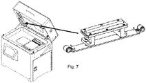
- Fig. 7 illustrates the position of the recoater within the XM200 demo model of a SLM machine.
- Fig. 8 illustrates a side view of the recoater bridge and the bulb holding portion of the recoater device, according to one embodiment of the disclosure. Many of the features are similar to those shown in Fig. 3 and therefore carry the same reference numerals.
- An advantage of the recoater mechanism is the adjustability built into it. The recoater can be adjusted so it is perfectly aligned. The overall height can also be adjusted, allowing for a wider range of different layer thicknesses.
- the two fine-thread adjustment screws 237 can be adjusted to raise and lower each end of the recoater, therefore changing L1 and L2 and adjusting the height of the recoater bulb 239.
- the adjustment screws 237 can be finger-adjusted or can also be adjusted with hex keys for extremely fine adjustment.
- the compression springs 244 fix the bulb holding portion in place on the recoater bridge.
- Fig. 9 illustrates an alternative side view of the recoater when in use, according to one embodiment of the disclosure. Many of the features are similar to those shown in Fig. 2 and therefore carry the same reference numerals.
- the recoater bridge is attached to the guide shaft 229 using the linear bearing and the bearing mount. In use, the recoater bridge and bulb holding portion are held below the guide shaft so that the recoater bulb 239 moves build powder across the top of the build plate of the SLM device.
- the method of fixing the bulb holding portion in place using compression springs provides the advantage of compliance.
- the springs can compress which allows the recoater bulb 239 to flex and pivot. This compliance increases reliability in the process, since the recoater can interfere or "crash” on a slightly deformed part being formed, and recover. This reduces damage to both the recoater bulb and to the part being formed.
- a non-compliant device under the same circumstances can damage the recoating bulb, or the part being formed, causing the process to fail. This then would require a re-start of the build which is costly and time-consuming. If the bulb is damaged it must be replaced with a new bulb.
- the compliance in the present disclosure reduces the frequency of replacing the recoater bulb in the system, which can be difficult and time-consuming.
- Fig. 10 illustrates a method of changing the recoater bulb in the recoater mechanism, according to one embodiment of the present disclosure. Many of the features are similar to those shown in Fig. 3 and therefore carry the same reference numerals.
- Fig. 10(a) shows the six bulb holder captive screws 243 can be removed. As shown in Fig. 10(b) , the bulb clamp 238 can then be removed, the bulb 239 is replaced. The bulb clamp 238 is then re-installed by replacing the bulb holder captive screws, as shown in Fig. 10(c) . This allows the bulb to be easily changed. This requires the recoater mechanism to be mounted on the lid of the additive manufacturing machine in order to access the screws.
- Fig. 11 illustrates an alternative method of changing the recoater bulb in the recoater mechanism, according to a further embodiment of the present disclosure. Many of the features are similar to those shown in Fig. 3 and therefore carry the same reference numerals.
- Fig. 11(a) shows the six bulb holder captive screws 243 can be removed.
- the bulb clamp 238 is mounted on a hinge, allowing it to swing open instead of having to completely remove it, as shown in Fig. 11(b) .
- the bulb 239 can then be replaced.
- the bulb clamp 238 is then reinstalled by replacing the bulb holder captive screws as shown in Fig. 11(c) . This configuration also allows the bulb to be easily changed.
- Fig. 12 illustrates an alternative method of changing the recoater bulb in the recoater mechanism, according to a further embodiment of the present disclosure. Many of the features are similar to those shown in Fig. 3 and therefore carry the same reference numerals.
- Fig. 12(a) shows the six bulb holder captive screws 243 are placed in holes that have a saddle/pear shape.
- the bulb clamp 238 has saddle/pear shape holes, allowing it slide (step S1) such that the screws 243 move into the wider end of the holes, and the clamp 243 can be lifted off (step S2), as shown in Figure 12(b) .
- the bulb clamp 243 is reinstalled by placing the clamp down and sliding it in the opposite direction. This configuration also allows the bulb to be easily changed.
- the bulb holder captive screws 243 do not have to be removed in order to remove the clamp 238.
- This embodiment does not require access to the screws, the cover plate 238 can be simply slid off. This reduces the possibility of screws accidentally going/falling into the system, which may damage the system.
Landscapes
- Chemical & Material Sciences (AREA)
- Engineering & Computer Science (AREA)
- Materials Engineering (AREA)
- Manufacturing & Machinery (AREA)
- Physics & Mathematics (AREA)
- Mechanical Engineering (AREA)
- Optics & Photonics (AREA)
Claims (15)
- Wiederbeschichtungsvorrichtung für ein additives Fertigungsverfahren, wobei die Vorrichtung umfasst:ein Wiederbeschichtungsglied (239) zum Führen eines Materialvolumens zu einem Zielbereich;eine Tragstruktur (241), auf welcher das Wiederbeschichtungsglied (239) montiert ist;eine Wiederbeschichtungsbasis (231), welche mit der Tragstruktur gekoppelt ist undmindestens eine Vorspannkomponente (244), welche zwischen der Wiederbeschichtungsbasis (231) und der Tragstruktur gekoppelt ist;wobei die Wiederbeschichtungsvorrichtung derart konfiguriert ist, dass das Wiederbeschichtungsglied (239) sich in einer ersten Richtung entlang einer Längsdimension des Zielbereichs bewegt, undwobei die mindestens eine Vorspannkomponente (244) konfiguriert ist, um das Wiederbeschichtungsglied (239) in einer zweiten Richtung zu bewegen, welche von der ersten Richtung unterschiedlich ist.
- Wiederbeschichtungsvorrichtung nach Anspruch 1, wobei das Wiederbeschichtungsglied (239) sich in der zweiten Richtung bewegt, wenn das Wiederbeschichtungsglied (239) um eine Achse entlang der ersten Richtung schwenkt.
- Wiederbeschichtungsvorrichtung nach einem der Ansprüche 1 oder 2, wobei das Wiederbeschichtungsglied (239) sich in der zweiten Richtung bewegt, wenn das Wiederbeschichtungsglied (239) um eine Achse schwenkt, welche quer zur ersten Richtung liegt.
- Wiederbeschichtungsvorrichtung nach Anspruch 1, ferner umfassend mindestens eine Vorspannkomponente (244), welche an einem jeweiligen Ende der Tragstruktur angeordnet und zwischen der Wiederbeschichtungsbasis (231) und der Tragstruktur gekoppelt ist.
- Wiederbeschichtungsvorrichtung nach einem der vorhergehenden Ansprüche, wobei die mindestens eine Vorspannkomponente (244) eine Druckfeder ist.
- Wiederbeschichtungsvorrichtung nach einem der vorhergehenden Ansprüche, ferner umfassend mindestens eine einstellbare Fixierkomponente (237) an einem jeweiligen Ende der Tragstruktur, wobei die mindestens eine einstellbare Fixierkomponente (237) jeweils zwischen der Wiederbeschichtungsbasis (231) und der Tragstruktur gekoppelt ist; und
optional wobei eine Höhe des Wiederbeschichtungsglieds (231) im Verhältnis zu dem Zielbereich durch die mindestens eine Fixierkomponente (237) einstellbar ist. - Wiederbeschichtungsvorrichtung nach Anspruch 6, wobei die mindestens eine Fixierkomponente (237) eine Höheneinstellschraube ist.
- Wiederbeschichtungsvorrichtung nach einem der Ansprüche 6 oder 7, wobei ein Ende des Wiederbeschichtungsglieds (239) unabhängig von einem anderen Ende des Wiederbeschichtungsglieds (239) angehoben oder abgesenkt wird.
- Wiederbeschichtungsvorrichtung nach einem der vorhergehenden Ansprüche, wobei das Wiederbeschichtungsglied (239) ein Wiederbeschichtungskolben oder eine Wiederbeschichtungsklinge ist.
- Wiederbeschichtungsvorrichtung nach einem der vorhergehenden Ansprüche, ferner umfassend eine Vielzahl von Längsschienen (229), wobei das Wiederbeschichtungsglied (239) entlang der Vielzahl von Längsschienen (229) in der ersten Richtung beweglich ist.
- Wiederbeschichtungsvorrichtung nach einem der vorhergehenden Ansprüche, ferner umfassend:einen Wiederbeschichtungsgliedhalter (240); undeine Wiederbeschichtungsgliedklemme (238);wobei Ränder des Wiederbeschichtungsglieds (239) zwischen dem Wiederbeschichtungsgliedhalter (240) und der Wiederbeschichtungsgliedklemme (238) fixiert sind.
- Wiederbeschichtungsvorrichtung nach Anspruch 11, wobei die Wiederbeschichtungsgliedklemme (238) von dem Wiederbeschichtungsgliedhalter (240) lösbar ist, und optional durch das Entfernen einer oder mehrerer Schrauben (243); oderwobei die Wiederbeschichtungsgliedklemme (238) auf dem Wiederbeschichtungsgliedhalter (240) unter Verwendung eines Scharniers montiert ist, wobei das Scharnier durch Entfernen einer oder mehrerer Schrauben (243) wirksam wird; oderwobei die Wiederbeschichtungsgliedklemme (238) entlang einer Fläche des Wiederbeschichtungsgliedhalters (240) verschiebbar.
- Wiederbeschichtungsvorrichtung nach einem der vorhergehenden Ansprüche, wobei das Wiederbeschichtungsglied (239) Gummi oder ein Kunststoffmaterial umfasst.
- Dreidimensionaler (3D) Drucker, umfassend die Wiederbeschichtungsvorrichtung nach einem der vorhergehenden Ansprüche.
- Verfahren zum Herstellen einer Wiederbeschichtungsvorrichtung für einen additiven Fertigungsprozess, wobei das Verfahren umfasst:Formen eines Wiederbeschichtungsglieds (239) zum Führen eines Materialvolumens zu einem Zielbereich;Formen einer Tragstruktur (241), auf welcher das Wiederbeschichtungsglied (239) montiert ist;Formen einer Wiederbeschichtungsbasis (231), welche mit der Tragstruktur gekoppelt ist; undFormen von mindestens einer Vorspannkomponente (244), welche zwischen der Wiederbeschichtungsbasis (231) und der Tragstruktur gekoppelt ist,wobei das Wiederbeschichtungsglied (239) konfiguriert ist, um sich in einer ersten Richtung entlang einer Längsdimension des Zielbereichs zu bewegen, undwobei die mindestens eine Vorspannkomponente (244) konfiguriert ist, um das Wiederbeschichtungsglied (239) in einer zweiten Richtung zu bewegen, welche von der ersten Richtung unterschiedlich ist.
Applications Claiming Priority (2)
| Application Number | Priority Date | Filing Date | Title |
|---|---|---|---|
| US15/665,603 US10758979B2 (en) | 2017-08-01 | 2017-08-01 | Recoating device for additive manufacturing |
| PCT/EP2018/070613 WO2019025373A1 (en) | 2017-08-01 | 2018-07-30 | RE-COATING DEVICE FOR ADDITIVE MANUFACTURE |
Publications (2)
| Publication Number | Publication Date |
|---|---|
| EP3661731A1 EP3661731A1 (de) | 2020-06-10 |
| EP3661731B1 true EP3661731B1 (de) | 2022-05-11 |
Family
ID=63047389
Family Applications (1)
| Application Number | Title | Priority Date | Filing Date |
|---|---|---|---|
| EP18746948.1A Not-in-force EP3661731B1 (de) | 2017-08-01 | 2018-07-30 | Wiederbeschichtungsvorrichtung für die generative fertigung |
Country Status (3)
| Country | Link |
|---|---|
| US (1) | US10758979B2 (de) |
| EP (1) | EP3661731B1 (de) |
| WO (1) | WO2019025373A1 (de) |
Families Citing this family (7)
| Publication number | Priority date | Publication date | Assignee | Title |
|---|---|---|---|---|
| CN108080638B (zh) * | 2018-01-30 | 2023-07-04 | 华中科技大学 | 一种非晶合金箔材的激光3d打印成形系统及成形方法 |
| EP3976297A4 (de) * | 2019-05-28 | 2023-02-15 | Vulcanforms Inc. | Neubeschichtungssystem für die generative fertigung |
| US11247396B2 (en) | 2019-05-28 | 2022-02-15 | Vulcanforms Inc. | Recoater system for additive manufacturing |
| US11718025B2 (en) | 2019-09-06 | 2023-08-08 | Jeol Ltd. | Additive manufacturing machine |
| US12350739B2 (en) * | 2019-12-12 | 2025-07-08 | Arcam Ab | Additive manufacturing apparatuses with separable process chamber housing portions and methods of use |
| CN110899699B (zh) * | 2019-12-22 | 2022-02-15 | 安徽哈特三维科技有限公司 | 一种成型模具加工用选区激光融化装置 |
| DE102022106016A1 (de) | 2022-03-15 | 2023-09-21 | Dmg Mori Additive Gmbh | Anlage zum schichtweisen Aufbauen von Gegenständen aus einem Werkstoffpulver mit wechselbarer Beschichtereinheit |
Family Cites Families (4)
| Publication number | Priority date | Publication date | Assignee | Title |
|---|---|---|---|---|
| FR2790418B1 (fr) | 1999-03-01 | 2001-05-11 | Optoform Sarl Procedes De Prot | Procede de prototypage rapide permettant l'utilisation de materiaux pateux, et dispositif pour sa mise en oeuvre |
| EP1234625A1 (de) | 2001-02-21 | 2002-08-28 | Trumpf Werkzeugmaschinen GmbH + Co. KG | Verfahren und Vorrichtung zur Herstellung eines Formkörpers durch selektives Laserschmelzen |
| US7585450B2 (en) * | 2005-09-30 | 2009-09-08 | 3D Systems, Inc. | Rapid prototyping and manufacturing system and method |
| NL2013862B1 (en) * | 2014-11-24 | 2016-10-11 | Additive Ind Bv | Apparatus for producing an object by means of additive manufacturing. |
-
2017
- 2017-08-01 US US15/665,603 patent/US10758979B2/en not_active Expired - Fee Related
-
2018
- 2018-07-30 EP EP18746948.1A patent/EP3661731B1/de not_active Not-in-force
- 2018-07-30 WO PCT/EP2018/070613 patent/WO2019025373A1/en not_active Ceased
Also Published As
| Publication number | Publication date |
|---|---|
| EP3661731A1 (de) | 2020-06-10 |
| WO2019025373A1 (en) | 2019-02-07 |
| US10758979B2 (en) | 2020-09-01 |
| US20190039135A1 (en) | 2019-02-07 |
Similar Documents
| Publication | Publication Date | Title |
|---|---|---|
| EP3661731B1 (de) | Wiederbeschichtungsvorrichtung für die generative fertigung | |
| WO2018202643A1 (en) | Additive manufacturing apparatus comprising gantry device using reflecting elements to direct laser beam to movable scanner | |
| CN109622954B (zh) | 层叠造型装置和层叠造型物的制造方法 | |
| CN107087400B (zh) | 用于基于粉末来增材制造的机器和方法 | |
| US10583529B2 (en) | Additive manufacturing method using a plurality of synchronized laser beams | |
| US11278988B2 (en) | Additive manufacturing method using large and small beam sizes | |
| CN105522149B (zh) | 叠层成型装置 | |
| EP1704989A2 (de) | Vorrichtung und Verfahren zum Ausrichten eines entfernbaren Formzimmers in einem Prozesszimmer | |
| US9839960B2 (en) | Three dimensional printer | |
| US20170072643A1 (en) | Adjustable z-axis printhead module for additive manufacturing system | |
| US20170173883A1 (en) | Additive manufacturing method using tilted scanners | |
| CA3027111C (en) | Slot die additive manufacturing apparatus and manufacturing method | |
| EP3023177A1 (de) | Trägeranordnung zur verwendung in einem verfahren zur gleichzeitigen reparatur einer mehrzahl von komponenten mittels generativer herstellung | |
| WO2014138386A1 (en) | Powder bed fusion systems, apparatus, and processes for multi-material part production | |
| CN110116499A (zh) | 用于三维结构的增材制造的设备和方法 | |
| CN110666166B (zh) | 一种多激光高精度的3d打印机及其打印方法 | |
| EP3650204B1 (de) | Vorrichtung zur generativen fertigung dreidimensionaler objekte | |
| US11958250B2 (en) | Reclamation system for additive manufacturing | |
| CN204712462U (zh) | 一种3d打印机 | |
| US20200198235A1 (en) | Lifting system for device and a method for generatively manufacturing a three-dimensional object | |
| US11958114B2 (en) | Lamination molding apparatus | |
| WO2021086905A1 (en) | Melt pool monitoring in multi-laser systems | |
| CN110696241B (zh) | 成形模清洁装置及方法、树脂成形装置以及树脂成形品制造方法 | |
| RU165868U1 (ru) | Устройство для получения изделий из порошковых материалов | |
| CN208141058U (zh) | Slm设备的光学系统装置 |
Legal Events
| Date | Code | Title | Description |
|---|---|---|---|
| STAA | Information on the status of an ep patent application or granted ep patent |
Free format text: STATUS: UNKNOWN |
|
| STAA | Information on the status of an ep patent application or granted ep patent |
Free format text: STATUS: THE INTERNATIONAL PUBLICATION HAS BEEN MADE |
|
| PUAI | Public reference made under article 153(3) epc to a published international application that has entered the european phase |
Free format text: ORIGINAL CODE: 0009012 |
|
| STAA | Information on the status of an ep patent application or granted ep patent |
Free format text: STATUS: REQUEST FOR EXAMINATION WAS MADE |
|
| 17P | Request for examination filed |
Effective date: 20200203 |
|
| AK | Designated contracting states |
Kind code of ref document: A1 Designated state(s): AL AT BE BG CH CY CZ DE DK EE ES FI FR GB GR HR HU IE IS IT LI LT LU LV MC MK MT NL NO PL PT RO RS SE SI SK SM TR |
|
| AX | Request for extension of the european patent |
Extension state: BA ME |
|
| DAV | Request for validation of the european patent (deleted) | ||
| DAX | Request for extension of the european patent (deleted) | ||
| GRAP | Despatch of communication of intention to grant a patent |
Free format text: ORIGINAL CODE: EPIDOSNIGR1 |
|
| STAA | Information on the status of an ep patent application or granted ep patent |
Free format text: STATUS: GRANT OF PATENT IS INTENDED |
|
| RIC1 | Information provided on ipc code assigned before grant |
Ipc: B33Y 30/00 20150101ALI20211025BHEP Ipc: B22F 12/00 20210101ALI20211025BHEP Ipc: B22F 10/20 20210101ALI20211025BHEP Ipc: B29C 64/205 20170101ALI20211025BHEP Ipc: B29C 64/124 20170101AFI20211025BHEP |
|
| INTG | Intention to grant announced |
Effective date: 20211125 |
|
| RAP3 | Party data changed (applicant data changed or rights of an application transferred) |
Owner name: XACT METAL INC. |
|
| GRAS | Grant fee paid |
Free format text: ORIGINAL CODE: EPIDOSNIGR3 |
|
| GRAA | (expected) grant |
Free format text: ORIGINAL CODE: 0009210 |
|
| STAA | Information on the status of an ep patent application or granted ep patent |
Free format text: STATUS: THE PATENT HAS BEEN GRANTED |
|
| AK | Designated contracting states |
Kind code of ref document: B1 Designated state(s): AL AT BE BG CH CY CZ DE DK EE ES FI FR GB GR HR HU IE IS IT LI LT LU LV MC MK MT NL NO PL PT RO RS SE SI SK SM TR |
|
| REG | Reference to a national code |
Ref country code: GB Ref legal event code: FG4D |
|
| REG | Reference to a national code |
Ref country code: CH Ref legal event code: EP |
|
| REG | Reference to a national code |
Ref country code: AT Ref legal event code: REF Ref document number: 1491031 Country of ref document: AT Kind code of ref document: T Effective date: 20220515 |
|
| REG | Reference to a national code |
Ref country code: DE Ref legal event code: R096 Ref document number: 602018035453 Country of ref document: DE |
|
| REG | Reference to a national code |
Ref country code: IE Ref legal event code: FG4D |
|
| REG | Reference to a national code |
Ref country code: LT Ref legal event code: MG9D |
|
| REG | Reference to a national code |
Ref country code: NL Ref legal event code: MP Effective date: 20220511 |
|
| REG | Reference to a national code |
Ref country code: AT Ref legal event code: MK05 Ref document number: 1491031 Country of ref document: AT Kind code of ref document: T Effective date: 20220511 |
|
| PG25 | Lapsed in a contracting state [announced via postgrant information from national office to epo] |
Ref country code: SE Free format text: LAPSE BECAUSE OF FAILURE TO SUBMIT A TRANSLATION OF THE DESCRIPTION OR TO PAY THE FEE WITHIN THE PRESCRIBED TIME-LIMIT Effective date: 20220511 Ref country code: PT Free format text: LAPSE BECAUSE OF FAILURE TO SUBMIT A TRANSLATION OF THE DESCRIPTION OR TO PAY THE FEE WITHIN THE PRESCRIBED TIME-LIMIT Effective date: 20220912 Ref country code: NO Free format text: LAPSE BECAUSE OF FAILURE TO SUBMIT A TRANSLATION OF THE DESCRIPTION OR TO PAY THE FEE WITHIN THE PRESCRIBED TIME-LIMIT Effective date: 20220811 Ref country code: NL Free format text: LAPSE BECAUSE OF FAILURE TO SUBMIT A TRANSLATION OF THE DESCRIPTION OR TO PAY THE FEE WITHIN THE PRESCRIBED TIME-LIMIT Effective date: 20220511 Ref country code: LT Free format text: LAPSE BECAUSE OF FAILURE TO SUBMIT A TRANSLATION OF THE DESCRIPTION OR TO PAY THE FEE WITHIN THE PRESCRIBED TIME-LIMIT Effective date: 20220511 Ref country code: HR Free format text: LAPSE BECAUSE OF FAILURE TO SUBMIT A TRANSLATION OF THE DESCRIPTION OR TO PAY THE FEE WITHIN THE PRESCRIBED TIME-LIMIT Effective date: 20220511 Ref country code: GR Free format text: LAPSE BECAUSE OF FAILURE TO SUBMIT A TRANSLATION OF THE DESCRIPTION OR TO PAY THE FEE WITHIN THE PRESCRIBED TIME-LIMIT Effective date: 20220812 Ref country code: FI Free format text: LAPSE BECAUSE OF FAILURE TO SUBMIT A TRANSLATION OF THE DESCRIPTION OR TO PAY THE FEE WITHIN THE PRESCRIBED TIME-LIMIT Effective date: 20220511 Ref country code: ES Free format text: LAPSE BECAUSE OF FAILURE TO SUBMIT A TRANSLATION OF THE DESCRIPTION OR TO PAY THE FEE WITHIN THE PRESCRIBED TIME-LIMIT Effective date: 20220511 Ref country code: BG Free format text: LAPSE BECAUSE OF FAILURE TO SUBMIT A TRANSLATION OF THE DESCRIPTION OR TO PAY THE FEE WITHIN THE PRESCRIBED TIME-LIMIT Effective date: 20220811 Ref country code: AT Free format text: LAPSE BECAUSE OF FAILURE TO SUBMIT A TRANSLATION OF THE DESCRIPTION OR TO PAY THE FEE WITHIN THE PRESCRIBED TIME-LIMIT Effective date: 20220511 |
|
| PG25 | Lapsed in a contracting state [announced via postgrant information from national office to epo] |
Ref country code: RS Free format text: LAPSE BECAUSE OF FAILURE TO SUBMIT A TRANSLATION OF THE DESCRIPTION OR TO PAY THE FEE WITHIN THE PRESCRIBED TIME-LIMIT Effective date: 20220511 Ref country code: PL Free format text: LAPSE BECAUSE OF FAILURE TO SUBMIT A TRANSLATION OF THE DESCRIPTION OR TO PAY THE FEE WITHIN THE PRESCRIBED TIME-LIMIT Effective date: 20220511 Ref country code: LV Free format text: LAPSE BECAUSE OF FAILURE TO SUBMIT A TRANSLATION OF THE DESCRIPTION OR TO PAY THE FEE WITHIN THE PRESCRIBED TIME-LIMIT Effective date: 20220511 Ref country code: IS Free format text: LAPSE BECAUSE OF FAILURE TO SUBMIT A TRANSLATION OF THE DESCRIPTION OR TO PAY THE FEE WITHIN THE PRESCRIBED TIME-LIMIT Effective date: 20220911 |
|
| PG25 | Lapsed in a contracting state [announced via postgrant information from national office to epo] |
Ref country code: SM Free format text: LAPSE BECAUSE OF FAILURE TO SUBMIT A TRANSLATION OF THE DESCRIPTION OR TO PAY THE FEE WITHIN THE PRESCRIBED TIME-LIMIT Effective date: 20220511 Ref country code: SK Free format text: LAPSE BECAUSE OF FAILURE TO SUBMIT A TRANSLATION OF THE DESCRIPTION OR TO PAY THE FEE WITHIN THE PRESCRIBED TIME-LIMIT Effective date: 20220511 Ref country code: RO Free format text: LAPSE BECAUSE OF FAILURE TO SUBMIT A TRANSLATION OF THE DESCRIPTION OR TO PAY THE FEE WITHIN THE PRESCRIBED TIME-LIMIT Effective date: 20220511 Ref country code: EE Free format text: LAPSE BECAUSE OF FAILURE TO SUBMIT A TRANSLATION OF THE DESCRIPTION OR TO PAY THE FEE WITHIN THE PRESCRIBED TIME-LIMIT Effective date: 20220511 Ref country code: DK Free format text: LAPSE BECAUSE OF FAILURE TO SUBMIT A TRANSLATION OF THE DESCRIPTION OR TO PAY THE FEE WITHIN THE PRESCRIBED TIME-LIMIT Effective date: 20220511 Ref country code: CZ Free format text: LAPSE BECAUSE OF FAILURE TO SUBMIT A TRANSLATION OF THE DESCRIPTION OR TO PAY THE FEE WITHIN THE PRESCRIBED TIME-LIMIT Effective date: 20220511 |
|
| REG | Reference to a national code |
Ref country code: DE Ref legal event code: R119 Ref document number: 602018035453 Country of ref document: DE |
|
| PG25 | Lapsed in a contracting state [announced via postgrant information from national office to epo] |
Ref country code: MC Free format text: LAPSE BECAUSE OF FAILURE TO SUBMIT A TRANSLATION OF THE DESCRIPTION OR TO PAY THE FEE WITHIN THE PRESCRIBED TIME-LIMIT Effective date: 20220511 |
|
| REG | Reference to a national code |
Ref country code: CH Ref legal event code: PL |
|
| PLBE | No opposition filed within time limit |
Free format text: ORIGINAL CODE: 0009261 |
|
| STAA | Information on the status of an ep patent application or granted ep patent |
Free format text: STATUS: NO OPPOSITION FILED WITHIN TIME LIMIT |
|
| REG | Reference to a national code |
Ref country code: BE Ref legal event code: MM Effective date: 20220731 |
|
| PG25 | Lapsed in a contracting state [announced via postgrant information from national office to epo] |
Ref country code: AL Free format text: LAPSE BECAUSE OF FAILURE TO SUBMIT A TRANSLATION OF THE DESCRIPTION OR TO PAY THE FEE WITHIN THE PRESCRIBED TIME-LIMIT Effective date: 20220511 |
|
| 26N | No opposition filed |
Effective date: 20230214 |
|
| GBPC | Gb: european patent ceased through non-payment of renewal fee |
Effective date: 20220811 |
|
| PG25 | Lapsed in a contracting state [announced via postgrant information from national office to epo] |
Ref country code: LU Free format text: LAPSE BECAUSE OF NON-PAYMENT OF DUE FEES Effective date: 20220730 Ref country code: LI Free format text: LAPSE BECAUSE OF NON-PAYMENT OF DUE FEES Effective date: 20220731 Ref country code: FR Free format text: LAPSE BECAUSE OF NON-PAYMENT OF DUE FEES Effective date: 20220731 Ref country code: CH Free format text: LAPSE BECAUSE OF NON-PAYMENT OF DUE FEES Effective date: 20220731 |
|
| PG25 | Lapsed in a contracting state [announced via postgrant information from national office to epo] |
Ref country code: SI Free format text: LAPSE BECAUSE OF FAILURE TO SUBMIT A TRANSLATION OF THE DESCRIPTION OR TO PAY THE FEE WITHIN THE PRESCRIBED TIME-LIMIT Effective date: 20220511 Ref country code: DE Free format text: LAPSE BECAUSE OF NON-PAYMENT OF DUE FEES Effective date: 20230201 Ref country code: BE Free format text: LAPSE BECAUSE OF NON-PAYMENT OF DUE FEES Effective date: 20220731 |
|
| PG25 | Lapsed in a contracting state [announced via postgrant information from national office to epo] |
Ref country code: IE Free format text: LAPSE BECAUSE OF NON-PAYMENT OF DUE FEES Effective date: 20220730 |
|
| PG25 | Lapsed in a contracting state [announced via postgrant information from national office to epo] |
Ref country code: GB Free format text: LAPSE BECAUSE OF NON-PAYMENT OF DUE FEES Effective date: 20220811 |
|
| PG25 | Lapsed in a contracting state [announced via postgrant information from national office to epo] |
Ref country code: IT Free format text: LAPSE BECAUSE OF FAILURE TO SUBMIT A TRANSLATION OF THE DESCRIPTION OR TO PAY THE FEE WITHIN THE PRESCRIBED TIME-LIMIT Effective date: 20220511 |
|
| PG25 | Lapsed in a contracting state [announced via postgrant information from national office to epo] |
Ref country code: MK Free format text: LAPSE BECAUSE OF FAILURE TO SUBMIT A TRANSLATION OF THE DESCRIPTION OR TO PAY THE FEE WITHIN THE PRESCRIBED TIME-LIMIT Effective date: 20220511 Ref country code: CY Free format text: LAPSE BECAUSE OF FAILURE TO SUBMIT A TRANSLATION OF THE DESCRIPTION OR TO PAY THE FEE WITHIN THE PRESCRIBED TIME-LIMIT Effective date: 20220511 |
|
| PG25 | Lapsed in a contracting state [announced via postgrant information from national office to epo] |
Ref country code: HU Free format text: LAPSE BECAUSE OF FAILURE TO SUBMIT A TRANSLATION OF THE DESCRIPTION OR TO PAY THE FEE WITHIN THE PRESCRIBED TIME-LIMIT; INVALID AB INITIO Effective date: 20180730 |
|
| PG25 | Lapsed in a contracting state [announced via postgrant information from national office to epo] |
Ref country code: MT Free format text: LAPSE BECAUSE OF FAILURE TO SUBMIT A TRANSLATION OF THE DESCRIPTION OR TO PAY THE FEE WITHIN THE PRESCRIBED TIME-LIMIT Effective date: 20220511 |
|
| PG25 | Lapsed in a contracting state [announced via postgrant information from national office to epo] |
Ref country code: BG Free format text: LAPSE BECAUSE OF FAILURE TO SUBMIT A TRANSLATION OF THE DESCRIPTION OR TO PAY THE FEE WITHIN THE PRESCRIBED TIME-LIMIT Effective date: 20220511 |
|
| PG25 | Lapsed in a contracting state [announced via postgrant information from national office to epo] |
Ref country code: BG Free format text: LAPSE BECAUSE OF FAILURE TO SUBMIT A TRANSLATION OF THE DESCRIPTION OR TO PAY THE FEE WITHIN THE PRESCRIBED TIME-LIMIT Effective date: 20220511 |
|
| PG25 | Lapsed in a contracting state [announced via postgrant information from national office to epo] |
Ref country code: TR Free format text: LAPSE BECAUSE OF FAILURE TO SUBMIT A TRANSLATION OF THE DESCRIPTION OR TO PAY THE FEE WITHIN THE PRESCRIBED TIME-LIMIT Effective date: 20220511 |