EP3661686B1 - Composant de dispositif d'allumage produit par un procede de transfert de metal froid - Google Patents
Composant de dispositif d'allumage produit par un procede de transfert de metal froid Download PDFInfo
- Publication number
- EP3661686B1 EP3661686B1 EP18755263.3A EP18755263A EP3661686B1 EP 3661686 B1 EP3661686 B1 EP 3661686B1 EP 18755263 A EP18755263 A EP 18755263A EP 3661686 B1 EP3661686 B1 EP 3661686B1
- Authority
- EP
- European Patent Office
- Prior art keywords
- substrate
- alloy
- metal
- process according
- feed wire
- Prior art date
- Legal status (The legal status is an assumption and is not a legal conclusion. Google has not performed a legal analysis and makes no representation as to the accuracy of the status listed.)
- Active
Links
- 229910052751 metal Inorganic materials 0.000 title claims description 133
- 239000002184 metal Substances 0.000 title claims description 132
- 238000000034 method Methods 0.000 title claims description 113
- 230000008569 process Effects 0.000 title claims description 95
- 238000012546 transfer Methods 0.000 title claims description 21
- 239000000758 substrate Substances 0.000 claims description 222
- 239000000956 alloy Substances 0.000 claims description 133
- 229910045601 alloy Inorganic materials 0.000 claims description 132
- BASFCYQUMIYNBI-UHFFFAOYSA-N platinum Chemical group [Pt] BASFCYQUMIYNBI-UHFFFAOYSA-N 0.000 claims description 32
- 238000004519 manufacturing process Methods 0.000 claims description 31
- PXHVJJICTQNCMI-UHFFFAOYSA-N Nickel Chemical compound [Ni] PXHVJJICTQNCMI-UHFFFAOYSA-N 0.000 claims description 16
- 238000010891 electric arc Methods 0.000 claims description 13
- 229910001026 inconel Inorganic materials 0.000 claims description 13
- 230000003247 decreasing effect Effects 0.000 claims description 6
- 229910052759 nickel Inorganic materials 0.000 claims description 6
- 238000000462 isostatic pressing Methods 0.000 claims description 3
- RYGMFSIKBFXOCR-UHFFFAOYSA-N Copper Chemical group [Cu] RYGMFSIKBFXOCR-UHFFFAOYSA-N 0.000 claims description 2
- 229910000990 Ni alloy Inorganic materials 0.000 claims description 2
- 230000032258 transport Effects 0.000 claims description 2
- 229910000510 noble metal Inorganic materials 0.000 description 26
- 150000002739 metals Chemical class 0.000 description 23
- 239000007789 gas Substances 0.000 description 22
- KDLHZDBZIXYQEI-UHFFFAOYSA-N Palladium Chemical compound [Pd] KDLHZDBZIXYQEI-UHFFFAOYSA-N 0.000 description 21
- 239000000203 mixture Substances 0.000 description 21
- 229910052741 iridium Inorganic materials 0.000 description 19
- 229910052707 ruthenium Inorganic materials 0.000 description 19
- 238000003466 welding Methods 0.000 description 19
- 239000010948 rhodium Substances 0.000 description 17
- 229910052763 palladium Inorganic materials 0.000 description 16
- 229910052697 platinum Inorganic materials 0.000 description 16
- 229910052703 rhodium Inorganic materials 0.000 description 15
- 239000010931 gold Substances 0.000 description 13
- 229910052737 gold Inorganic materials 0.000 description 12
- 239000010949 copper Substances 0.000 description 11
- 230000033001 locomotion Effects 0.000 description 11
- 239000000463 material Substances 0.000 description 11
- 229910052802 copper Inorganic materials 0.000 description 8
- 238000005520 cutting process Methods 0.000 description 6
- 229910052709 silver Inorganic materials 0.000 description 6
- 229910018487 Ni—Cr Inorganic materials 0.000 description 5
- 229910052782 aluminium Inorganic materials 0.000 description 5
- 239000011261 inert gas Substances 0.000 description 5
- 229910052742 iron Inorganic materials 0.000 description 5
- 229910052750 molybdenum Inorganic materials 0.000 description 5
- 229910052762 osmium Inorganic materials 0.000 description 5
- 238000012545 processing Methods 0.000 description 5
- 239000010944 silver (metal) Substances 0.000 description 5
- 229910052719 titanium Inorganic materials 0.000 description 5
- 238000001125 extrusion Methods 0.000 description 4
- 229910052748 manganese Inorganic materials 0.000 description 4
- 238000002844 melting Methods 0.000 description 4
- 230000008018 melting Effects 0.000 description 4
- 229910052758 niobium Inorganic materials 0.000 description 4
- KJTLSVCANCCWHF-UHFFFAOYSA-N Ruthenium Chemical compound [Ru] KJTLSVCANCCWHF-UHFFFAOYSA-N 0.000 description 3
- 239000000919 ceramic Substances 0.000 description 3
- 229910052804 chromium Inorganic materials 0.000 description 3
- 238000004590 computer program Methods 0.000 description 3
- 238000000151 deposition Methods 0.000 description 3
- 238000005553 drilling Methods 0.000 description 3
- GKOZUEZYRPOHIO-UHFFFAOYSA-N iridium atom Chemical compound [Ir] GKOZUEZYRPOHIO-UHFFFAOYSA-N 0.000 description 3
- 238000003754 machining Methods 0.000 description 3
- SYQBFIAQOQZEGI-UHFFFAOYSA-N osmium atom Chemical compound [Os] SYQBFIAQOQZEGI-UHFFFAOYSA-N 0.000 description 3
- 230000036961 partial effect Effects 0.000 description 3
- MHOVAHRLVXNVSD-UHFFFAOYSA-N rhodium atom Chemical compound [Rh] MHOVAHRLVXNVSD-UHFFFAOYSA-N 0.000 description 3
- 229910052721 tungsten Inorganic materials 0.000 description 3
- 229910052725 zinc Inorganic materials 0.000 description 3
- 229910052726 zirconium Inorganic materials 0.000 description 3
- 235000001674 Agaricus brunnescens Nutrition 0.000 description 2
- BQCADISMDOOEFD-UHFFFAOYSA-N Silver Chemical compound [Ag] BQCADISMDOOEFD-UHFFFAOYSA-N 0.000 description 2
- 241000656145 Thyrsites atun Species 0.000 description 2
- MCMNRKCIXSYSNV-UHFFFAOYSA-N Zirconium dioxide Chemical compound O=[Zr]=O MCMNRKCIXSYSNV-UHFFFAOYSA-N 0.000 description 2
- 239000010953 base metal Substances 0.000 description 2
- 239000011324 bead Substances 0.000 description 2
- 230000008901 benefit Effects 0.000 description 2
- 230000015572 biosynthetic process Effects 0.000 description 2
- 230000008021 deposition Effects 0.000 description 2
- 238000009760 electrical discharge machining Methods 0.000 description 2
- 238000010304 firing Methods 0.000 description 2
- PCHJSUWPFVWCPO-UHFFFAOYSA-N gold Chemical compound [Au] PCHJSUWPFVWCPO-UHFFFAOYSA-N 0.000 description 2
- 239000000155 melt Substances 0.000 description 2
- 230000035515 penetration Effects 0.000 description 2
- 229910052702 rhenium Inorganic materials 0.000 description 2
- 229910052706 scandium Inorganic materials 0.000 description 2
- 239000004332 silver Substances 0.000 description 2
- 229910052715 tantalum Inorganic materials 0.000 description 2
- 229910052723 transition metal Inorganic materials 0.000 description 2
- 150000003624 transition metals Chemical class 0.000 description 2
- 229910052720 vanadium Inorganic materials 0.000 description 2
- QNRATNLHPGXHMA-XZHTYLCXSA-N (r)-(6-ethoxyquinolin-4-yl)-[(2s,4s,5r)-5-ethyl-1-azabicyclo[2.2.2]octan-2-yl]methanol;hydrochloride Chemical compound Cl.C([C@H]([C@H](C1)CC)C2)CN1[C@@H]2[C@H](O)C1=CC=NC2=CC=C(OCC)C=C21 QNRATNLHPGXHMA-XZHTYLCXSA-N 0.000 description 1
- 241000237858 Gastropoda Species 0.000 description 1
- 229910052772 Samarium Inorganic materials 0.000 description 1
- QCWXUUIWCKQGHC-UHFFFAOYSA-N Zirconium Chemical compound [Zr] QCWXUUIWCKQGHC-UHFFFAOYSA-N 0.000 description 1
- 239000000654 additive Substances 0.000 description 1
- 230000000996 additive effect Effects 0.000 description 1
- 238000010923 batch production Methods 0.000 description 1
- 230000008859 change Effects 0.000 description 1
- 238000005097 cold rolling Methods 0.000 description 1
- 238000001816 cooling Methods 0.000 description 1
- 239000011258 core-shell material Substances 0.000 description 1
- 238000005260 corrosion Methods 0.000 description 1
- 230000007797 corrosion Effects 0.000 description 1
- 239000013078 crystal Substances 0.000 description 1
- 230000001351 cycling effect Effects 0.000 description 1
- 230000007423 decrease Effects 0.000 description 1
- 238000000280 densification Methods 0.000 description 1
- 230000001419 dependent effect Effects 0.000 description 1
- 238000013461 design Methods 0.000 description 1
- 238000007730 finishing process Methods 0.000 description 1
- 238000010438 heat treatment Methods 0.000 description 1
- 238000001513 hot isostatic pressing Methods 0.000 description 1
- 238000005098 hot rolling Methods 0.000 description 1
- 238000005304 joining Methods 0.000 description 1
- 229910052745 lead Inorganic materials 0.000 description 1
- 230000000670 limiting effect Effects 0.000 description 1
- 230000007246 mechanism Effects 0.000 description 1
- 239000007769 metal material Substances 0.000 description 1
- 238000012544 monitoring process Methods 0.000 description 1
- 230000003647 oxidation Effects 0.000 description 1
- 238000007254 oxidation reaction Methods 0.000 description 1
- 238000012805 post-processing Methods 0.000 description 1
- 239000010970 precious metal Substances 0.000 description 1
- 238000002360 preparation method Methods 0.000 description 1
- 238000003825 pressing Methods 0.000 description 1
- 229910001404 rare earth metal oxide Inorganic materials 0.000 description 1
- 230000002829 reductive effect Effects 0.000 description 1
- KZUNJOHGWZRPMI-UHFFFAOYSA-N samarium atom Chemical compound [Sm] KZUNJOHGWZRPMI-UHFFFAOYSA-N 0.000 description 1
- 230000006641 stabilisation Effects 0.000 description 1
- 229910052718 tin Inorganic materials 0.000 description 1
- 238000011144 upstream manufacturing Methods 0.000 description 1
- 239000002699 waste material Substances 0.000 description 1
- 229910052727 yttrium Inorganic materials 0.000 description 1
- VWQVUPCCIRVNHF-UHFFFAOYSA-N yttrium atom Chemical compound [Y] VWQVUPCCIRVNHF-UHFFFAOYSA-N 0.000 description 1
- RUDFQVOCFDJEEF-UHFFFAOYSA-N yttrium(III) oxide Inorganic materials [O-2].[O-2].[O-2].[Y+3].[Y+3] RUDFQVOCFDJEEF-UHFFFAOYSA-N 0.000 description 1
Images
Classifications
-
- B—PERFORMING OPERATIONS; TRANSPORTING
- B23—MACHINE TOOLS; METAL-WORKING NOT OTHERWISE PROVIDED FOR
- B23K—SOLDERING OR UNSOLDERING; WELDING; CLADDING OR PLATING BY SOLDERING OR WELDING; CUTTING BY APPLYING HEAT LOCALLY, e.g. FLAME CUTTING; WORKING BY LASER BEAM
- B23K9/00—Arc welding or cutting
- B23K9/04—Welding for other purposes than joining, e.g. built-up welding
- B23K9/042—Built-up welding on planar surfaces
-
- B—PERFORMING OPERATIONS; TRANSPORTING
- B23—MACHINE TOOLS; METAL-WORKING NOT OTHERWISE PROVIDED FOR
- B23K—SOLDERING OR UNSOLDERING; WELDING; CLADDING OR PLATING BY SOLDERING OR WELDING; CUTTING BY APPLYING HEAT LOCALLY, e.g. FLAME CUTTING; WORKING BY LASER BEAM
- B23K9/00—Arc welding or cutting
- B23K9/04—Welding for other purposes than joining, e.g. built-up welding
-
- B—PERFORMING OPERATIONS; TRANSPORTING
- B23—MACHINE TOOLS; METAL-WORKING NOT OTHERWISE PROVIDED FOR
- B23K—SOLDERING OR UNSOLDERING; WELDING; CLADDING OR PLATING BY SOLDERING OR WELDING; CUTTING BY APPLYING HEAT LOCALLY, e.g. FLAME CUTTING; WORKING BY LASER BEAM
- B23K35/00—Rods, electrodes, materials, or media, for use in soldering, welding, or cutting
- B23K35/02—Rods, electrodes, materials, or media, for use in soldering, welding, or cutting characterised by mechanical features, e.g. shape
- B23K35/0255—Rods, electrodes, materials, or media, for use in soldering, welding, or cutting characterised by mechanical features, e.g. shape for use in welding
- B23K35/0261—Rods, electrodes, wires
-
- B—PERFORMING OPERATIONS; TRANSPORTING
- B23—MACHINE TOOLS; METAL-WORKING NOT OTHERWISE PROVIDED FOR
- B23K—SOLDERING OR UNSOLDERING; WELDING; CLADDING OR PLATING BY SOLDERING OR WELDING; CUTTING BY APPLYING HEAT LOCALLY, e.g. FLAME CUTTING; WORKING BY LASER BEAM
- B23K35/00—Rods, electrodes, materials, or media, for use in soldering, welding, or cutting
- B23K35/22—Rods, electrodes, materials, or media, for use in soldering, welding, or cutting characterised by the composition or nature of the material
- B23K35/24—Selection of soldering or welding materials proper
- B23K35/30—Selection of soldering or welding materials proper with the principal constituent melting at less than 1550 degrees C
- B23K35/3033—Ni as the principal constituent
- B23K35/304—Ni as the principal constituent with Cr as the next major constituent
-
- B—PERFORMING OPERATIONS; TRANSPORTING
- B23—MACHINE TOOLS; METAL-WORKING NOT OTHERWISE PROVIDED FOR
- B23K—SOLDERING OR UNSOLDERING; WELDING; CLADDING OR PLATING BY SOLDERING OR WELDING; CUTTING BY APPLYING HEAT LOCALLY, e.g. FLAME CUTTING; WORKING BY LASER BEAM
- B23K35/00—Rods, electrodes, materials, or media, for use in soldering, welding, or cutting
- B23K35/22—Rods, electrodes, materials, or media, for use in soldering, welding, or cutting characterised by the composition or nature of the material
- B23K35/24—Selection of soldering or welding materials proper
- B23K35/32—Selection of soldering or welding materials proper with the principal constituent melting at more than 1550 degrees C
- B23K35/322—Selection of soldering or welding materials proper with the principal constituent melting at more than 1550 degrees C a Pt-group metal as principal constituent
-
- B—PERFORMING OPERATIONS; TRANSPORTING
- B23—MACHINE TOOLS; METAL-WORKING NOT OTHERWISE PROVIDED FOR
- B23K—SOLDERING OR UNSOLDERING; WELDING; CLADDING OR PLATING BY SOLDERING OR WELDING; CUTTING BY APPLYING HEAT LOCALLY, e.g. FLAME CUTTING; WORKING BY LASER BEAM
- B23K9/00—Arc welding or cutting
- B23K9/16—Arc welding or cutting making use of shielding gas
- B23K9/173—Arc welding or cutting making use of shielding gas and of a consumable electrode
-
- B—PERFORMING OPERATIONS; TRANSPORTING
- B23—MACHINE TOOLS; METAL-WORKING NOT OTHERWISE PROVIDED FOR
- B23K—SOLDERING OR UNSOLDERING; WELDING; CLADDING OR PLATING BY SOLDERING OR WELDING; CUTTING BY APPLYING HEAT LOCALLY, e.g. FLAME CUTTING; WORKING BY LASER BEAM
- B23K9/00—Arc welding or cutting
- B23K9/23—Arc welding or cutting taking account of the properties of the materials to be welded
- B23K9/232—Arc welding or cutting taking account of the properties of the materials to be welded of different metals
-
- C—CHEMISTRY; METALLURGY
- C22—METALLURGY; FERROUS OR NON-FERROUS ALLOYS; TREATMENT OF ALLOYS OR NON-FERROUS METALS
- C22C—ALLOYS
- C22C19/00—Alloys based on nickel or cobalt
-
- C—CHEMISTRY; METALLURGY
- C22—METALLURGY; FERROUS OR NON-FERROUS ALLOYS; TREATMENT OF ALLOYS OR NON-FERROUS METALS
- C22C—ALLOYS
- C22C19/00—Alloys based on nickel or cobalt
- C22C19/03—Alloys based on nickel or cobalt based on nickel
-
- H—ELECTRICITY
- H01—ELECTRIC ELEMENTS
- H01T—SPARK GAPS; OVERVOLTAGE ARRESTERS USING SPARK GAPS; SPARKING PLUGS; CORONA DEVICES; GENERATING IONS TO BE INTRODUCED INTO NON-ENCLOSED GASES
- H01T13/00—Sparking plugs
- H01T13/20—Sparking plugs characterised by features of the electrodes or insulation
- H01T13/39—Selection of materials for electrodes
-
- H—ELECTRICITY
- H01—ELECTRIC ELEMENTS
- H01T—SPARK GAPS; OVERVOLTAGE ARRESTERS USING SPARK GAPS; SPARKING PLUGS; CORONA DEVICES; GENERATING IONS TO BE INTRODUCED INTO NON-ENCLOSED GASES
- H01T21/00—Apparatus or processes specially adapted for the manufacture or maintenance of spark gaps or sparking plugs
- H01T21/02—Apparatus or processes specially adapted for the manufacture or maintenance of spark gaps or sparking plugs of sparking plugs
-
- B—PERFORMING OPERATIONS; TRANSPORTING
- B23—MACHINE TOOLS; METAL-WORKING NOT OTHERWISE PROVIDED FOR
- B23K—SOLDERING OR UNSOLDERING; WELDING; CLADDING OR PLATING BY SOLDERING OR WELDING; CUTTING BY APPLYING HEAT LOCALLY, e.g. FLAME CUTTING; WORKING BY LASER BEAM
- B23K2101/00—Articles made by soldering, welding or cutting
- B23K2101/006—Vehicles
-
- B—PERFORMING OPERATIONS; TRANSPORTING
- B23—MACHINE TOOLS; METAL-WORKING NOT OTHERWISE PROVIDED FOR
- B23K—SOLDERING OR UNSOLDERING; WELDING; CLADDING OR PLATING BY SOLDERING OR WELDING; CUTTING BY APPLYING HEAT LOCALLY, e.g. FLAME CUTTING; WORKING BY LASER BEAM
- B23K2101/00—Articles made by soldering, welding or cutting
- B23K2101/36—Electric or electronic devices
Definitions
- the present invention relates to methods for the production of a platinum group metal or alloy ignition device component by cold metal transfer (CMT).
- CMT cold metal transfer
- noble metal or noble metal-containing alloy it is often necessary or desirable to attach a noble metal or noble metal-containing alloy to another metal or alloy to form an assembly.
- the other metal or alloy may also be noble metal-based or it may be another type of metal or alloy.
- the noble metals consist of ruthenium (Ru), rhodium (Rh), palladium (Pd), silver (Ag), osmium (Os), iridium (Ir), platinum (Pt) and gold (Au).
- ignition system devices such as spark plugs.
- Such devices include components such as a central electrode which is usually connected to the ignition system, and a ground or side electrode which is grounded by connection to the metal shell of the ignition device.
- the tips of the ignition device component (for example, the tip of the central electrode or ground electrode), from which a spark is generated during use, often (but not always) consists of a noble metal or noble metal-containing alloy (for example a metal or alloy comprising gold, silver, ruthenium, rhodium, palladium, osmium, iridium or platinum).
- the tip of the electrode must be able to withstand very harsh conditions of high temperature and high voltage during operation of the device and so must be made from more resilient and often more expensive material.
- the remainder of the electrodes, which do not experience such harsh conditions, are often formed from different, less expensive metal or alloy materials (for example Ni-Cr alloy and/or copper).
- a common way to manufacture the electrode in such ignition system devices is to draw noble metal (for example, a platinum group metal (PGM)) and base metal (typically Inconel, a Ni-Cr alloy) wires. These wires are then fed in such a way that the metals touch and a laser or friction weld is carried out. Typically, once welded, the noble metal and base wire assembly is then cut on both sides, such that a welded small stub of material is formed. Typically, the base metal element of this stub is then itself welded onto a substrate to form the electrodes, after each substrate has been (separately) independently manufactured. Commonly used substrates for this purpose are based on Inconel, a Ni-Cr alloy, with a Cu core. Such substrates are pre-formed by the co-extrusion of the two metals and are well-known
- An alternative method currently used to manufacture the electrode in such devices is to laser-weld a piece or 'slug' of sectioned Pt wire onto the substrate to form the electrode tip, after each substrate has been independently manufactured.
- a common way to manufacture the electrode in such devices is to laser-weld a piece or 'slug' of sectioned noble metal wire onto the substrate to form an electrode tip, after each substrate has been independently manufactured.
- Commonly used substrates for this purpose are based on Inconel, a Ni-Cr alloy, with a Cu core. Such substrates are pre-formed by the co-extrusion of the two metals and are well-known. Examples of using welding techniques to attach a precious metal tip to a surface of a spark plug can be found in US2007/103046 , US2008/050264 and WO2009/034318 .
- US 7 851 984 B2 describes a method of manufacturaing an ignition device by providing a metal electrode, providing a wire having a free end and another end carried by a feed mechanism, and reflowing the free end to form a firing tip. Reflowing is achieved using a high energy laser beam to create a melt pool of the wire material on a fire tip region of the electrode body, moving the electrode body and laser vertically away from one another along an axis of the laser beam during the reflowing step. The melt pool is cooled to form a solidified firing tip surface.
- a first aspect of the invention is a process for the production of an ignition device component by cold metal transfer comprising:
- platinum group metal refers to the elements ruthenium (Ru), rhodium (Rh), palladium (Pd), osmium (Os), iridium (Ir), and platinum (Pt).
- Cold metal transfer is a known process.
- DE 10 2012 212042 describes a drill bit comprising a clamping shaft, a drill sleeve with a drilling case bottom, and a cutting element. The cutting element is produced using a cold metal transfer method.
- DE 10 2011 007694 describes a drilling tool comprising a working head, which comprises a base body, a main cutting element and a secondary cutting element. However, these references do not describe the application of cold metal transfer to produce an ignition device.
- CMT cold metal transfer
- the CMT process is loss-free and therefore much more desirable than the sectioning and laser welding of PGM wire.
- the present CMT method can be used to directly produce a shaped attachment without any material loss and without the need for separate machining steps. It is also possible to use the same length of feed wire and tailor the resulting attachment length simply by selection of suitable CMT process parameters, rather than requiring a range of sectioned wire lengths to be available from an earlier sectioning process.
- metal or alloy from a feed wire is deposited onto a substrate by CMT to form an attachment on the substrate.
- CMT effectively forms a weld joint at the junction between the surface of the substrate and the deposited attachment.
- the attachment is therefore not simply deposited onto the surface but becomes securely fixed to the substrate.
- metal from a feed wire is deposited onto the substrate by CMT to form an attachment on the substrate.
- the feed wire may comprise of one or more metals selected from Co, Al, Ni, W, Fe, Zn, Mn, Sc, Ti, V, Cr, Cu, Zr, Nb, Mo, Ru, Rh, Pd, Ag, Hf, Ta, Re, Os, Ir, Pt and Au.
- the feed wire comprises or consists of one or more metals selected from Ru, Rh, Pd, Ag, Os, Ir, Pt and Au.
- the feed wire comprises or consists of one or more metals selected from Au, Ag, Ru, Rh, Pd, Ir and Pt.
- the feed wire comprises or consists of one or more metals selected from Ru, Rh, Pd, Ir and Pt.
- the feed wire comprises or consists of two or more metals selected from Ru, Rh, Pd, Ag, Os, Ir, Au and Pt.
- the feed wire comprises or consists of two or more metals selected from Ru, Rh, Pd, Ag, Ir, Au and Pt.
- the feed wire comprises or consists of two or more metals selected from Ru, Rh, Pd, Ir, and Pt.
- the feed wire comprises or consists of one or more metals selected from Ru and Ir.
- alloy from a feed wire is deposited onto a substrate by CMT to form an attachment on the substrate
- the feed wire comprises or consists of an alloy of one or more of Ru, Rh, Pd, Ag, Os, Ir, Pt and Au with one or more other elements, for example one or more other metals.
- the one or more other elements in the alloy may be selected from Co, Al, Ni, W, Fe, Zn, Mn, Sc, Ti, V, Cr, Cu, Zr, Nb, Mo, Ru, Rh, Pd, Ag, Hf, Ta, Re, Os, Ir, Pt and Au.
- the feed wire comprises or consists of an alloy of one or more of Ru, Rh, Pd, Ag, Ir, Pt and Au, with one or more other elements, for example one or more other metals.
- the feed wire comprises or consists of an alloy of one or more of Ru, Rh, Pd, Ir and Pt with one or more other elements, for example one or more other metals.
- the alloy comprises or consists of an alloy of one or more of Ru and Ir with one or more other metals, and it is particularly preferred that the alloy comprises or consists of an alloy containing Ru or Ir as the primary component, with one or more other metals, such alloys having particular utility in ignition devices.
- the alloy comprises or consists of an alloy of two or more of Ru, Rh, Pd, Ag, Os, Ir, Pt and Au.
- the alloys contain additional components selected from one or more of Y (yttrium), Zr (zirconium) and Sm (samarium).
- the alloys contain Zr.
- Zr zirconium
- the inclusion of these elements may ductilise the alloys. It is also believed that these elements (in particular Zr) may hinder the dislocation movement through grain boundaries (i.e. the boundaries between crystal lattices at different orientations) and hence limit or slow grain growth.
- the alloy may comprise other, non-alloy components.
- the alloy also comprises a ceramic oxide component.
- a ceramic oxide component may increase grain stabilisation of the alloy and improve spark erosion properties (which may be advantageous in ignition device components in particular).
- Non-limiting examples of such ceramic oxides are Y 2 O 3 , ZrO 2 , and rare earth oxides.
- the metal or alloy deposited onto the substrate comprises a noble metal or alloy thereof. More preferably, the metal or alloy deposited onto the substrate comprises a PGM or alloy thereof.
- an ignition device component is limited to a method comprising:
- the diameter of the feed wire used will depend on the desired diameter of attachment.
- the metal or alloy feed wire has a diameter of at least 0.3 mm, for example at least 0.4 mm or at least 0.5 mm.
- the attachment has a diameter of up to 2.5 mm, for example up to 2 mm or up to 1.5 mm. Any suitable method known to the skilled person may be used to manufacture a metal or alloy feed wire of the appropriate composition and size.
- the attachment which is manufactured by CMT is deposited on and fixed to a surface of a metal or alloy substrate.
- the substrate may comprise any suitable metal or alloy, or mixture of metals and/or alloys.
- the substrate is a body formed by the co-extrusion of two different metals or alloys or any other method of fabrication known to the skilled person.
- the substrate comprises a metal or alloy different to the metal or alloy which is deposited on the substrate by CMT. In some embodiments, the substrate does not comprise any metal or alloy which is present in the feed wire or in the material deposited on the substrate. In some embodiments, the substrate does not comprise any PGM.
- the substrate may preferably be a portion of a central or ground electrode of an ignition device.
- the attachment then forms the 'tip' of the electrode from which a spark may be generated during use.
- the substrate more preferably may be a portion of a central electrode of an ignition device. As will be appreciated, this is a preferred feature of the process for producing an ignition device.
- the substrate may comprise a conductive metal or alloy.
- the substrate comprises one or more metals selected from Ag, Au, Cu, Al, Mo, Zn, W, Ni, Fe, Pd, Pt, Sn, Pb, Ti or an alloy of any one of these with one or more other elements, for example one or more other metals.
- the substrate comprises one or more metals selected from Cu and Ni or an alloy of any one of these with one or more other elements, for example one or more other metals, and this feature is particular preferred in the process for producing an ignition device.
- the substrate comprises a first region comprising a first metal or alloy and a second region comprising a second metal or alloy, different from the first metal or alloy.
- the first region is a core region (core) which is surrounded at least in part by the second region (shell).
- the first and second regions may be formed by the co-extrusion of the first and second metals or alloys.
- the first region comprises or consists of a conductive metal.
- the first region comprises or consists of a transition metal, such as Cu.
- the second region comprises or consists of a conductive metal.
- the second region comprises or consists of an alloy, such as a Ni alloy.
- the second region comprises or consists of Inconel.
- the substrate comprises a core comprising Cu surrounded at least in part by an external portion (shell) comprising Ni or an alloy of Ni, such as Inconel.
- the surface onto which the wire is deposited during CMT may comprise Ni or an alloy of Ni, such as Inconel, and preferably the surface may comprise Ni or an alloy of Ni.
- the primary component may be Ni and the other element(s) in the alloy of Ni may be selected from Cr, Fe, Mo, Nb, Co, Mn, Cu, Al, Ti, Si, C, S, P and B.
- the most abundant element in the alloy is Ni
- the second most abundant element in the alloy is Cr
- the alloy may comprise one or more other alloyed elements selected from Fe, Mo, Nb, Co, Mn, Cu, Al, Ti, Si, C, S, P and B.
- the alloy is Inconel.
- Such "core-shell" type substrates for use as part of an ignition device electrode are well-known to the skilled person and commercially available.
- the overall shape of the substrate is not particularly limited. The skilled person will be able to select a suitable shape depending on the intended ignition device (or component) application.
- the substrate has an elongate structure.
- Such substrates have one dimension which is longer than the other two dimensions by a factor of at least 2, for example at least 3, for example at least 4.
- the cross-sectional geometry of such elongate substrates is not particularly limited but may be selected from circular, elliptical, triangular, square, rectangular, trapezoid, rhombic, pentagonal, hexagonal or octagonal.
- Such substrates may comprise features on the surface of the substrate, such as ridges, bosses or recesses.
- the substrate is substantially cylindrical.
- Central electrodes of ignition devices such as spark plugs are often of cylindrical shape, the 'tip' of the electrode from which a spark is generated being located at one end of the cylinder.
- the surface of the cylindrical substrate onto which material is deposited by CMT is one of the end surfaces of the cylinder, which may be substantially planar.
- substantially cylindrical we mean that the substrate will generally be of elongate structure with a circular or close to circular cross-section (for example, the cross section may be slightly elliptical in shape rather than a perfect circle). Furthermore, “substantially cylindrical” does not exclude the presence of features on the surface of the substrate, such as ridges, bosses or recesses. The size and shape of the cross section of the substrate may be consistent along its length or may vary, for example such that the substrate has a tapered appearance.
- the size of the substrate is also not particularly limited and will depend upon the intended application of the ignition device (or component). As already mentioned, such substrates are commercially available and the process described herein may be adapted to be used with any such substrate. Generally, the substrate may have a length of 0.5 to 80 mm, for example 10 to 20 mm, depending on the design and the intended use.
- a quantity of metal or alloy from the feed wire is deposited onto a surface of the metal or alloy substrate and becomes mechanically bonded to the substrate by a weld-joint formed in the CMT process. This bond is much stronger than would be formed from mere deposition of molten metal onto a surface.
- a single deposit of metal or alloy may be made from the feed wire onto the substrate.
- the metal or alloy may cover the entire area of an exposed surface of the substrate once deposited, although multiple deposits are also contemplated and may be achieved by repetition of the steps of the processes described herein.
- the metal or alloy may be deposited to cover only a portion of an exposed surface of the substrate.
- the substrate is an elongate substrate, for example a substantially cylindrical as discussed above, the metal or alloy may be deposited onto one of the end faces of the substrate.
- the substrate is an ignition device component, for example an ignition device electrode, for example a spark plug electrode.
- the substrate may be any other suitable metal or alloy substrate, for example a lead-out wire of a sensor.
- CMT Cold metal transfer
- a feed wire is transferred to a substrate, under relatively 'cold' conditions (when compared with traditional arc welding techniques).
- CMT has been proposed as an alternative welding process to electric arc welding, due to the automation offered by CMT, the reduced thermal input and the formation of a cleaner weld to join the workpieces. See for example US 2009/026188 A1 and US 2008/156781 A1 .
- Such weld processes may be known by different terminology depending on the manufacturer of the welding system.
- ColdArc used by EWM
- RMD ball transfer used by Miller
- CBT used by Daihen
- ColdMIG used by Merkle
- STT used by Lincoln
- the CMT process used in the present application is different from the above-described CMT weld processes.
- the processes described herein transfer a section of the feed wire to the substrate by CMT, thereby forming a substantially elongate attachment on the substrate.
- Such processes have been known by the names 'CMT-pin', 'CMT-pike', 'CMT-ball', 'CMT-cone' and 'CMT-print', and are described for example in US 2011/0073579 .
- CMT also offers the possibility to produce, according to the present invention, components for ignition devices in an economical way while preserving desirable properties.
- the metal or alloy attachment is fully formed onto the substrate in a single sequence of steps performed by a CMT system, and little or no post-processing (such as finishing or isostatic pressing) is necessary.
- the process of the present invention for the production of an ignition device component comprises four main steps:
- a metal or alloy substrate and a metal or alloy feed wire are provided.
- the wire is disposed substantially perpendicularly to the surface of the substrate, such that movement of the wire in an axial direction varies the distance between the wire and the substrate, and movement of the wire in an axial direction towards the substrate brings an end of the wire into contact with the substrate.
- the movements of the feed wire may be performed manually.
- the feed wire may be provided in an automated wire feeder which is mounted on a robotic arm. In this way, the movements of the feed wire are precisely controlled by a computer program.
- the substrate may be held or fixed in position on a build plate, as discussed in more detail below
- step (ii) of the process an electric arc is ignited between the substrate and the feed wire.
- the electric arc facilitates partial melting of the metal or alloy at the tip of the wire and partial melting of the metal or alloy of the substrate adjacent the wire, such that transfer of the metal or alloy from the feed wire to the substrate can occur.
- Means to achieve this are a standard part of CMT processes and well-known to the skilled person, for example, from US 2011/0073579 A1 .
- step (iii) of the process the distance between a surface of the substrate and the feed wire is decreased until the feed wire contacts the substrate.
- the feed wire and substrate are thereby welded.
- the distance may be decreased by moving the feed wire towards the substrate. The contact between the feed wire and the substrate creates a short-circuit and the electric arc is extinguished.
- the final step (iv) of the CMT method comprises increasing the distance between the substrate and the feed wire to break the short circuit and deposit metal or alloy from the feed wire onto the surface of the substrate to form a metal or alloy attachment on the surface of the substrate.
- the relative movement of the feed wire and substrate in steps (iii) and (iv) may be automated through the use of a wire feeder mounted on a robotic arm driven by a computer program.
- the welding current may also be controlled by such a computer program.
- Non-limiting examples of attachment geometries which are achievable using the CMT method according to the invention include cylindrical (with substantially flat end surface), spherical, 'mushroom' geometries and pike geometries (elongate attachment tapering into a point). Examples of these attachment geometries are shown in the Figures.
- the CMT process may be carried out using a CMT system which is commercially available such as the TransPulsSynergic range or CMT Advanced system from Fronius.
- CMT systems are automated and include a wire feeder, a digitally controlled MIG/MAG power source, a cooling unit to cool the welding torch, a wire buffer to facilitate smooth motion of the wire and a robotic welding torch arm for accurate wire feed and constant contact pressure.
- the CMT process preferably comprises administering a shielding gas to the region surrounding the electric arc discharge.
- a shielding gas may be achieved by either the Metal Inert Gas (MIG) or Metal Active Gas (MAG) techniques well known in CMT processes and in the welding field more generally.
- MIG Metal Inert Gas
- MAG Metal Active Gas
- an inert gas or inert gas mixture is used as a shielding gas and is fed to the region surrounding the electric arc during the CMT process.
- the inert gas is selected from Ar, He and mixtures thereof.
- an active gas or active gas mixture is used as the shielding gas during CMT.
- the active gas mixture comprises CO 2 or H 2 or mixtures of these with one or more inert gases.
- MIG and MAG processes are sometimes together known as GMAW (Gas Metal Arc Welding).
- the active gas mixture comprises Ar and O 2 .
- the active gas mixture may comprise at least 1.5 vol% O 2 , for example at least 2 vol%, at least 2.5 vol% or at least 3 vol% O 2 and balance Ar.
- the active gas mixture may comprise up to 6 vol% O 2 , for example up to 5.5 vol%, up to 5 vol% or up to 4.5 vol% O 2 and balance Ar.
- the active gas mixture comprises Ar and CO 2 .
- the active gas mixture may comprise at least 4 vol% CO 2 , for example at least 4.5 vol% or at least 5 vol% CO 2 and balance Ar.
- the active gas mixture may comprise up to 30 vol% CO 2 , for example up to 25 vol%, up to 20 vol% or up to 15 vol% CO 2 and balance Ar.
- the active gas mixture may comprise Ar, O 2 and CO 2 .
- the active gas mixture may comprise at least 5 vol% CO 2 , at least 2 vol% O 2 and balance Ar.
- the active gas mixture may comprise up to 15 vol% CO 2 , up to 10 vol% O 2 and balance Ar.
- the active gas mixture comprises He, O 2 and CO 2 .
- the active gas mixture may comprise at least 5 vol% CO 2 , at least 2 vol% O 2 and balance He.
- the active gas mixture may comprise up to 15 vol% CO 2 , up to 10 vol% O 2 and balance He.
- the gas mixture comprises N 2 . This may be considered active or inert, depending on the identity of the metal or alloy to be transferred.
- composition of the shielding gas affects the stability of the arc, the metal transfer properties, the amount of spatter and the behaviour of the weld pool, such as its penetration and the resultant mechanical properties of the welded joint between the substrate and the attachment.
- the process comprises the production of a plurality of components of ignition devices using a CMT method, wherein a plurality of substrates is arranged in an array within a single CMT unit.
- the process may comprise the steps of providing a plurality of substrates arranged in an array within a single CMT unit such that each step of the process of the present invention may be performed in relation to each substrate simultaneously or sequentially.
- the process can be considered to be a batch process, providing two or more components in each "run" of the process.
- CMT unit refers to a system which is adapted to perform a CMT process. Such systems are known to the skilled person and are commercially available, as explained above.
- the entire process of cold metal transfer of metal to form a single attachment on a substrate takes a fraction of a second.
- the process is therefore highly efficient and can be used to manufacture a plurality of ignition device components per second, for example at least 5, at least 10, at least 15, at least 20, at least 25 or at least 30 per second.
- the plurality of substrates is arranged in a 2-dimensional array on the build plate.
- the plurality of substrates is arranged in a regular array, such as a triangular, square or hexagonal array on a build plate.
- the distance between two adjacent substrates is kept to a minimum. This ensures maximum efficiency of the CMT process.
- the metal or alloy substrate is held upon a build plate during the CMT process.
- the substrate may be held in position within the build plate by any suitable means or may sit within a suitable bore or recess defined by the build plate.
- the substrate may be held in position within said bore or recess by suitable means, for example by abutment between a protrusion from the surface of the substrate and a protrusion from the inner surface of the bore or recess.
- the protrusion from the inner surface of the bore or recess may comprise an annular ridge, such that a more stable platform is provided upon which the substrate rests. In this way, not only the axial position of the substrate is controlled but the lateral position of the substrate is also more stable.
- the substrate may sit upon the floor of the recess in the build plate.
- the axial position of the substrate within the bore or recess can be controlled, for example in order to ensure that the upper surfaces of the substrate and build plate are coplanar.
- the process may therefore comprise, prior to step (i), a step of arranging one or more substrates in position on a build plate.
- the process of the invention comprises, prior to step (i), providing a modified build plate comprising a bore or recess suitable for holding the metal or alloy substrate during the CMT process, and installing the build plate within an CMT unit.
- the modified build plate may comprise a plurality of bores or recesses into which an equal plurality of substrates may be placed.
- the modified build plate may comprise a plurality of bores or recesses arranged in an array, such as a triangular, square or hexagonal array.
- the process will further comprise a step of inserting one or more substrates into the one or more bores or recesses in the build plate.
- the modified build plate may be provided by drilling a conventional build plate in order to provide a suitable recess or bore.
- the substrate is located within the recess such that the upper surface of the substrate is substantially level with the upper surface of the build plate, or protrudes above the upper surface of the build plate by a clearance of less than or equal to 5 mm. In this way, it can be ensured that, for example, during CMT processes material is deposited only on the upper surface of the substrate.
- the substrates are individually moved (by hand or by robotic means) into position for the CMT process to make contact with the substrate and deposit the metal or alloy attachment.
- the process incorporates an automatic substrate feeding step in which substrates (for example, electrodes) are sorted and arranged in the correct positions and orientation within the CMT machine.
- the process may involve the use of a feeding machine which is able to provide a predetermined number of substrates and ensure that substrates are provided in the correct orientation.
- Such feeding machines include vibratory bowl feeders, which are known to the skilled person.
- a vibratory bowl feeder is used to place all substrates in the same desired orientation and dispense them one-by-one.
- the substrates, in the correct orientation provided by the feeding machine, may then be moved into the correct position using a handling robot which may grip one or a plurality of substrates at a time and move them from the output line of the feeding machine to the necessary location within the CMT machine so that the CMT process may be performed.
- a handling robot which may grip one or a plurality of substrates at a time and move them from the output line of the feeding machine to the necessary location within the CMT machine so that the CMT process may be performed.
- step (i) of providing a metal or alloy substrate in the CMT process according to the first aspect of the invention may include the following steps:
- the feeding machine may be a vibratory bowl feeder.
- a plurality of substrates will be fed into the feeding machine and will be oriented into the same orientation by vibration of the machine and motion of a conveyor.
- Substrates may be supplied to the feeding machine batch-wise, or a continuous supply may be provided.
- the plurality of substrates may all be identical, or may include groups of non-identical substrates, for example substrates of various sizes and/or various shapes. In the latter case, the feeding machine may also sort the substrates into different output lines based on their size and/or shape.
- step (ib) the plurality of substrates emerge from the feeding machine in a desired orientation, ready for collection and transportation to the CMT machine.
- substrates may be transported manually or preferably using a handling robot.
- Suitable handling robots are known to the skilled person and are able to grasp and transport a plurality of bodies such as the substrates described herein.
- the product of the CMT process according to the first aspect of the invention is a component of an ignition device which is an assembly comprising the metal or alloy substrate and a deposited metal or alloy attachment which is fused to the substrate.
- the product of a CMT process not covered by the present invention is a noble metal-containing component comprising the metal or alloy substrate and a CMT deposited attachment comprising a noble metal or alloy thereof, which is fused to the substrate.
- the attachment may have a tapered shape such that its cross-sectional area decreases with distance from the substrate to which it is attached
- the attachment may have a convex shape, for example a hemispherical shape or the shape of a spherical cap or dome.
- the attachment is the sparking tip of an electrode for use in an ignition device.
- the attachment is formed from a PGM metal or alloy, this provides particularly desirable properties when the attachment is used as the sparking tip.
- the attachment has high melting temperature and is less prone to spark erosion, thereby reducing the risk of mis-fire of the ignition device.
- the size of the attachment will of course depend on the size of the substrate and the intended application, and the skilled person can adjust the CMT method in order to manufacture an attachment of suitable size.
- the attachment has a length of at least 0.1 mm, for example at least 0.2 mm, at least 0.25 mm, at least 0.3 mm, at least 0.35 mm or at least 0.4 mm.
- the attachment has a length of up to 10 mm, for example up to 5 mm, up to 4 mm, up to 3 mm, for example up to 2.5 mm or up to 2 mm.
- the attachment has a width (diameter) of at least 0.3 mm, for example at least 0.4 mm or at least 0.5 mm.
- the attachment may have a width (diameter) of up to 2.5 mm, for example up to 2 mm or up to 1.5 mm.
- the gauge of the wire is preserved upon formation of the attachment, so the wire gauge chosen determines the thickness of the attachment formed during CMT.
- Other dimensions of the attachment such as its height as measured from the substrate surface, the diameter of any spherical features formed and the base penetration depth of the attachment are determined by the power source program of the CMT system.
- the process of the invention further comprises a step (v) selected from surface finishing and/or mechanical processing of at least a part of the component.
- the surface finishing step may comprise a 3D scanning process to determine the three-dimensional position of each component on the build plate and to feed this information into the CNC machining system.
- the accuracy of CNC finishing may depend upon the positioning accuracy of the substrates. So, performing a 3D scan of the substrate positions after welding ensures that the surface finishing process is accurate.
- Mechanical processing may include any process known to the skilled person for use to change the structure and/or density of CMT deposited structures.
- Non-limiting examples of mechanical processing techniques which may be used in step (iv) include bead peening, mechanical peening, hot or cold rolling or pressing, such as isostatic pressing, for example hot isostatic pressing and additive layer manufacturing (ALM).
- the mechanical processing may comprise a densification process.
- Densifying is a means to reduce the internal porosity of the CMT manufactured part. In this way, a denser attachment can be provided.
- the mechanical processing may be used to introduce controlled levels of mechanical work, which can either be left or be utilised in combination with moderate localised heating to create an equiaxed grain structure at the surface, or deeper depending on severity of treatment and the thermal regime employed.
- the equiaxed structure may be created at the joint with the substrate with the epitaxially grown directional grains being confined to the surface of the attachment.
- Such varied structures are expected to lead to improved stability of the electrode tip in respect of oxidation/corrosion but more significantly thermal and mechanical cycling. It will be appreciated that this may be particularly advantageous for the production of electrode tips in ignition devices.
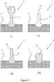
- Figure 1 shows various schematic cross-sectional representations of attachment geometries achievable using the CMT process of the invention.
- Figure 1 shows some of the possible 'pin' geometries which are possible to manufacture using the CMT process according to the invention.
- FIGS. 1 (a)-(d) show a different 'pin' geometry.
- an attachment has been deposited by CMT onto a substrate 5, which may be an ignition device electrode.
- Figure 1(a) shows an embodiment 1 in which an attachment ('pin') 11 with 'mushroom' geometry is attached to a substrate 5.
- the attachment 11 has a spherically shaped terminal portion 12 which extends to a greater diameter than the main stem of the attachment.
- the attachment 11 has been securely fixed to the substrate 5 by CMT from a metal or alloy feed wire.
- the substrate 5 may be Inconel alloy and the attachment 11 may be a noble metal or alloy thereof.
- Figure 1(b) shows an embodiment 2 in which an attachment ('pin') 21 with a 'flat' geometry is attached to a substrate 5.
- the attachment 21 has a terminal portion 22 which has a substantially planar end surface, such that the geometry of the attachment is substantially cylindrical.
- the attachment 21 has been securely fixed to the substrate 5 by CMT from a metal or alloy feed wire.
- the substrate 5 may be Inconel alloy and the attachment 21 may be a noble metal or alloy thereof.
- Figure 1(c) shows an embodiment 3 in which an attachment ('pin') 31 with a 'pike' or 'conical' geometry is attached to a substrate 5.
- the attachment 31 has a tapered terminal portion 32 which provides the terminal portion with a substantially conical geometry.
- the attachment 31 has been securely fixed to the substrate 5 by CMT from a metal or alloy feed wire.
- the substrate 5 may be Inconel alloy and the attachment 31 may be a noble metal or alloy thereof.
- Figure 1(d) shows an embodiment 4 in which an attachment ('pin') 41 with 'ball geometry is attached to a substrate 5.
- the attachment 41 has a spherical geometry similar to the terminal portion of the attachment 11 shown in Figure 1(a) , however the attachment 41 lacks the elongate stem portion present in attachment 11.
- the attachment 41 has been securely fixed to the substrate 5 by CMT from a metal or alloy feed wire.
- the substrate 5 may be Inconel alloy and the attachment 41 may be a noble metal or alloy thereof.
- any of the embodiments shown in Figure 1 would provide the advantages described herein and could be manufactured in an efficient and economical manner, with minimal waste material
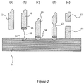
- Figure 2 is a schematic, cross-sectional representation of a typical cycle of the CMT process according to the invention. Steps (a)-(e) of Figure 2 represent steps through time within a single cycle (single attachment deposition) of the CMT process.
- a substrate 51 is provided which is typically a transition metal or alloy thereof, such as a Ni-Cr alloy.
- the substrate 51 may be Inconel.
- a feed wire 52 is provided adjacent the substrate 51, and the feed wire is oriented such that its axis is substantially perpendicular to the surface of the substrate 51.
- the feed wire is typically a noble metal or alloy thereof, such as an alloy of Ru or Ir.
- the feed wire 52 is held in a wire feeder mounted on a robotic arm which is part of a CMT system, such as the Fronius TransPulsSynergic system.
- step (b) of Figure 2 an electric arc 55 is ignited between the tip of the feed wire 52 and the portion of the surface of the substrate 54 which is adjacent the feed wire.
- the electric arc causes local partial melting in a zone 53 at the tip of the feed wire 52 and a zone 54 at the surface of the substrate 51.
- the ignition of the arc is controlled automatically by the CMT system, as is the voltage and current of the arc.
- the distance between the feed wire 52 and the substrate 51 is then decreased, for example by moving the wire feeder (not shown) or wire towards the substrate 51, until, as shown in step (c) of Figure 2 , the feed wire 52 and substrate 51 come into contact, creating a short-circuit. This creates a weld 56 between the feed wire 52 and substrate 51.
- step (d) of Figure 2 the distance between the feed wire 52 and the substrate 51 is increased, for example by moving the wire feeder (not shown) or wire away from the substrate 51 again. This creates a pinched portion 57 in the feed wire which eventually breaks to leave an attachment 58 welded to the surface of the substrate 51.
- the geometry of the attachment 58 shown in Figure 2 is 'flat', but the exact geometry can be varied by adjustment of welding parameters, such as the welding voltage, current and feed wire movement.
- the feed wire 52 can be moved by the robotic arm to another location (for example, adjacent another substrate), to deposit another attachment in the same way or deposit another attachment in the same way but with an alternative shape.
Landscapes
- Engineering & Computer Science (AREA)
- Mechanical Engineering (AREA)
- Physics & Mathematics (AREA)
- Plasma & Fusion (AREA)
- Chemical & Material Sciences (AREA)
- Materials Engineering (AREA)
- Manufacturing & Machinery (AREA)
- Metallurgy (AREA)
- Organic Chemistry (AREA)
- Spark Plugs (AREA)
- Arc Welding Control (AREA)
Claims (15)
- Procédé pour la production d'un composant de dispositif d'allumage par transfert de métal froid comprenant :(i) l'apport d'un substrat en métal ou en alliage (51) et d'un fil d'alimentation en métal ou alliage (52), dans lequel le fil d'alimentation (52) comprend un métal du groupe du platine ou un alliage comprenant un métal du groupe du platine ;(ii) l'allumage d'un arc électrique (55) entre le substrat (51) et le fil d'alimentation (52) ;(iii) la réduction de la distance entre la surface du substrat et le fil d'alimentation jusqu'à ce que le fil d'alimentation (52) entre en contact avec le substrat (51), créant ainsi un court-circuit ; et(iv) l'allongement de la distance entre le substrat et le fil d'alimentation afin de casser le court-circuit et de déposer du métal ou de l'alliage issu du fil d'alimentation sur la surface du substrat pour former un élément en métal ou alliage (58) sur la surface du substrat (51).
- Procédé selon la revendication 1 dans lequel le substrat comprend du nickel ou un alliage de nickel, comprenant facultativement un cœur en cuivre.
- Procédé selon la revendication 2 dans lequel le substrat comprend un alliage Inconel.
- Procédé selon l'une quelconque des revendications 1 à 3 comprenant la production d'une pluralité de composants utilisant une méthode de transfert de métal froid, dans lequel une pluralité de substrats est disposée en réseau à l'intérieur d'une unité simple de transfert de métal froid.
- Procédé selon la revendication 4 comprenant les étapes de réalisation (i) à (iv) pour chaque substrat dans le réseau simultanément ou successivement.
- Procédé selon la revendication 4 ou 5 dans lequel l'espacement entre les points centraux sur les substrats adjacents se situe dans une étendue de 1 à 10 mm, par exemple 2 à 8 mm.
- Procédé selon l'une quelconque des revendications 1 à 6 dans lequel le substrat est situé à l'intérieur d'un retrait ou d'un alésage de la plaque fabriquée d'une unité de transfert de métal froid.
- Procédé selon la revendication 7 dans lequel le substrat est situé à l'intérieur du retrait de sorte que la surface supérieure du substrat est substantiellement de niveau avec la surface supérieure de la plaque fabriquée ou dépasse de la surface supérieure de la plaque fabriquée avec un espace inférieur ou égal à 5 mm.
- Procédé selon la revendication 7 ou 8 dans lequel le substrat est maintenu en position à l'intérieur du retrait ou de l'alésage.
- Procédé selon l'une quelconque des revendications précédentes dans lequel l'étape (i) d'apport d'un substrat en métal ou en alliage comprend les étapes suivantes :(ia) apport d'une pluralité de substrats non triés et non orientés dans un système d'alimentation ;(ib) orientation des substrats dans une orientation prédéterminée souhaitée utilisant le système d'alimentation ; et(ic) transport des substrats orientés depuis une ligne de sortie du système d'alimentation dans une position prédéterminée souhaitée à l'intérieur d'une unité de transfert de métal froid.
- Procédé selon la revendication 10 dans lequel le système d'alimentation est un bol vibrant d'alimentation.
- Procédé selon les revendications 10 ou 11 dans lequel les substrats sont transportés avec un robot de manutention, facultativement dans lequel le robot transporte une pluralité de substrats en même temps.
- Procédé selon l'une quelconque des revendications précédentes comprenant encore une étape (v) sélectionnée parmi la finition de surface et/ou la compression isostatique d'au moins une partie du composant.
- Procédé selon l'une quelconque des revendications précédentes qui est un procédé pour la production d'une électrode centrale ou de terre d'une bougie d'allumage.
- Procédé selon la revendication 14 qui est un procédé pour former la pointe d'une électrode centrale d'une bougie d'allumage sur un substrat qui correspond au reste de l'électrode centrale.
Applications Claiming Priority (2)
| Application Number | Priority Date | Filing Date | Title |
|---|---|---|---|
| GBGB1712503.0A GB201712503D0 (en) | 2017-08-03 | 2017-08-03 | Component proceduced for cold metal transfer process |
| PCT/GB2018/052197 WO2019025796A1 (fr) | 2017-08-03 | 2018-08-01 | Composant de dispositif d'allumage produit par un processus de transfert de métal à froid |
Publications (2)
| Publication Number | Publication Date |
|---|---|
| EP3661686A1 EP3661686A1 (fr) | 2020-06-10 |
| EP3661686B1 true EP3661686B1 (fr) | 2021-10-13 |
Family
ID=59894836
Family Applications (1)
| Application Number | Title | Priority Date | Filing Date |
|---|---|---|---|
| EP18755263.3A Active EP3661686B1 (fr) | 2017-08-03 | 2018-08-01 | Composant de dispositif d'allumage produit par un procede de transfert de metal froid |
Country Status (7)
| Country | Link |
|---|---|
| US (1) | US11331740B2 (fr) |
| EP (1) | EP3661686B1 (fr) |
| JP (1) | JP7179823B2 (fr) |
| KR (1) | KR102493928B1 (fr) |
| CN (1) | CN111065482B (fr) |
| GB (2) | GB201712503D0 (fr) |
| WO (1) | WO2019025796A1 (fr) |
Families Citing this family (5)
| Publication number | Priority date | Publication date | Assignee | Title |
|---|---|---|---|---|
| US11738401B2 (en) * | 2019-11-12 | 2023-08-29 | Caterpillar Inc. | Method for manufacturing t-shaped structures |
| DE212022000192U1 (de) | 2021-05-04 | 2024-02-20 | Federal-Mogul Ignition Gmbh | Zündkerzenelektrode |
| US11901705B2 (en) | 2021-07-22 | 2024-02-13 | Federal-Mogul Ignition Gmbh | Electrode tip assembly for a spark plug and method of manufacturing the same |
| US11621544B1 (en) | 2022-01-14 | 2023-04-04 | Federal-Mogul Ignition Gmbh | Spark plug electrode and method of manufacturing the same |
| US11831130B2 (en) | 2022-03-29 | 2023-11-28 | Federal-Mogul Ignition Gmbh | Spark plug, spark plug electrode, and method of manufacturing the same |
Family Cites Families (23)
| Publication number | Priority date | Publication date | Assignee | Title |
|---|---|---|---|---|
| GB2055319B (en) | 1979-02-28 | 1983-08-24 | Kharkov Aviat I Im Ne Zhukov | Method and device for dropping built-up arc welding with consumable electrode in shielding gas atmosphere |
| JPS618235A (ja) * | 1984-06-25 | 1986-01-14 | Mitsubishi Electric Corp | 自動組立装置 |
| US4826462A (en) * | 1988-08-19 | 1989-05-02 | Champion Spark Plug Company | Method for manufacturing a spark plug electrode |
| DE10025048A1 (de) | 2000-05-23 | 2001-12-06 | Beru Ag | Mittelelektrode mit Edelmetallarmierung |
| JP2003010969A (ja) * | 2001-06-29 | 2003-01-15 | Atsushi Niinuma | 溶接方法、並びにそれに用いるアーク溶接用トーチ、溶接材仮付け装置、及び溶接装置 |
| US7323811B2 (en) * | 2001-08-23 | 2008-01-29 | Federal-Mogul Ignition (U.K.) Limited | Noble metal tip for spark plug electrode and method of making same |
| US6759795B2 (en) | 2002-02-27 | 2004-07-06 | Ngk Spark Plug Co., Ltd. | Spark plug |
| JP2005093221A (ja) | 2003-09-17 | 2005-04-07 | Denso Corp | スパークプラグ |
| US7557495B2 (en) * | 2005-11-08 | 2009-07-07 | Paul Tinwell | Spark plug having precious metal pad attached to ground electrode and method of making same |
| US7498543B2 (en) * | 2006-03-22 | 2009-03-03 | Gm Global Technology Operations, Inc. | Method for joining or repairing metal surface parts |
| US7851984B2 (en) * | 2006-08-08 | 2010-12-14 | Federal-Mogul World Wide, Inc. | Ignition device having a reflowed firing tip and method of construction |
| WO2008082716A2 (fr) * | 2006-08-28 | 2008-07-10 | Federal-Mogul Corporation | Composition d'électrode pour dispositif d'allumage |
| GB0717959D0 (en) * | 2007-09-14 | 2007-10-31 | Spelectrode Ltd | Ignition device electrodes, and manufacture thereof |
| JP4426614B2 (ja) * | 2007-11-30 | 2010-03-03 | 日本特殊陶業株式会社 | 内燃機関用スパークプラグ |
| AT506217B1 (de) | 2008-05-28 | 2009-07-15 | Fronius Int Gmbh | Verfahren zur herstellung einer struktur an einer oberfläche eines metallischen werkstücks |
| JP4775447B2 (ja) * | 2009-01-20 | 2011-09-21 | 株式会社デンソー | 内燃機関用のスパークプラグ |
| CN102133677B (zh) * | 2011-01-28 | 2013-03-27 | 西安誉丰通号科技有限公司 | 钢轨表面改性防锈焊接装置及其轨面熔敷改性方法 |
| DE102011007694A1 (de) * | 2011-04-19 | 2012-10-25 | Robert Bosch Gmbh | Bohrwerkzeug bzw. Verfahren zur Herstellung eines Bohrwerkzeugs |
| AT513428B1 (de) | 2011-10-28 | 2014-08-15 | Fronius Int Gmbh | Verfahren zur Herstellung einer dreidimensionalen Struktur an der Oberfläche eines metallischen Werkstücks |
| JP5730807B2 (ja) * | 2012-04-13 | 2015-06-10 | 日本特殊陶業株式会社 | スパークプラグの製造方法およびスパークプラグ |
| DE102012212042A1 (de) * | 2012-07-10 | 2014-01-30 | Robert Bosch Gmbh | Bohrkrone |
| DE102014216293A1 (de) * | 2014-08-15 | 2016-02-18 | Mahle International Gmbh | Verfahren zur Erzeugung von turbulenzerzeugenden Elementen und Rohr mit turbulenzerzeugenden Elementen |
| US11590601B2 (en) * | 2019-09-20 | 2023-02-28 | GM Global Technology Operations LLC | Method of joining steel work-pieces having different gauge ratios |
-
2017
- 2017-08-03 GB GBGB1712503.0A patent/GB201712503D0/en not_active Ceased
-
2018
- 2018-08-01 EP EP18755263.3A patent/EP3661686B1/fr active Active
- 2018-08-01 US US16/634,222 patent/US11331740B2/en active Active
- 2018-08-01 WO PCT/GB2018/052197 patent/WO2019025796A1/fr unknown
- 2018-08-01 KR KR1020207002256A patent/KR102493928B1/ko active IP Right Grant
- 2018-08-01 GB GB1812539.3A patent/GB2565233B/en active Active
- 2018-08-01 JP JP2020503312A patent/JP7179823B2/ja active Active
- 2018-08-01 CN CN201880049258.7A patent/CN111065482B/zh active Active
Also Published As
| Publication number | Publication date |
|---|---|
| JP2020529700A (ja) | 2020-10-08 |
| CN111065482B (zh) | 2021-11-09 |
| CN111065482A (zh) | 2020-04-24 |
| JP7179823B2 (ja) | 2022-11-29 |
| US20210086279A1 (en) | 2021-03-25 |
| WO2019025796A1 (fr) | 2019-02-07 |
| GB201712503D0 (en) | 2017-09-20 |
| GB201812539D0 (en) | 2018-09-12 |
| GB2565233A (en) | 2019-02-06 |
| EP3661686A1 (fr) | 2020-06-10 |
| GB2565233B (en) | 2021-03-10 |
| US11331740B2 (en) | 2022-05-17 |
| KR20200036857A (ko) | 2020-04-07 |
| KR102493928B1 (ko) | 2023-02-06 |
Similar Documents
| Publication | Publication Date | Title |
|---|---|---|
| EP3661686B1 (fr) | Composant de dispositif d'allumage produit par un procede de transfert de metal froid | |
| EP3661675B1 (fr) | Procédé de fabrication additive d'un composant | |
| EP0587446B1 (fr) | Méthode de fabrication d'une bougie d'allumage | |
| US7851984B2 (en) | Ignition device having a reflowed firing tip and method of construction | |
| EP0355052A1 (fr) | Méthode de fabrication pour bougie d'allumage | |
| EP1275461A1 (fr) | Méthode et appareil de brasage, bobine de relais et méthode et appareil de brasage pour fabriquer la bobine de relais | |
| US3488841A (en) | Method for manufacturing electrical contact elements | |
| CA2041340C (fr) | Appareil servant a modifier la surface de pieces metalliques et methode connexe | |
| CN109715338B (zh) | 用于mig金属焊接的接触末端组件 | |
| US11777281B2 (en) | Spark plug electrode and method of manufacturing the same | |
| EP1245323A1 (fr) | Méthode et dispositif de fabrication d'une pièce par soudage par rechargement | |
| JPH0519185Y2 (fr) | ||
| Mitru et al. | Software management of GTAW welding parameters with an 8-axis adaptive robotic system by analyzing the results obtained on samples and test pieces | |
| CZ307844B6 (cs) | Způsob lokálního legování výrobků svařovacím 3D tiskem pomocí elektrického oblouku | |
| EP3304663B1 (fr) | Procédé de formation d'une électrode métallique sur l'isolateur en porcelaine d'une bougie d'allumage | |
| EA040501B1 (ru) | Узел контактного наконечника для сварки металлов металлическим электродом в инертном газе | |
| JPS55139180A (en) | Inert gas tungsten arc welding method |
Legal Events
| Date | Code | Title | Description |
|---|---|---|---|
| STAA | Information on the status of an ep patent application or granted ep patent |
Free format text: STATUS: UNKNOWN |
|
| STAA | Information on the status of an ep patent application or granted ep patent |
Free format text: STATUS: THE INTERNATIONAL PUBLICATION HAS BEEN MADE |
|
| PUAI | Public reference made under article 153(3) epc to a published international application that has entered the european phase |
Free format text: ORIGINAL CODE: 0009012 |
|
| STAA | Information on the status of an ep patent application or granted ep patent |
Free format text: STATUS: REQUEST FOR EXAMINATION WAS MADE |
|
| 17P | Request for examination filed |
Effective date: 20200212 |
|
| AK | Designated contracting states |
Kind code of ref document: A1 Designated state(s): AL AT BE BG CH CY CZ DE DK EE ES FI FR GB GR HR HU IE IS IT LI LT LU LV MC MK MT NL NO PL PT RO RS SE SI SK SM TR |
|
| AX | Request for extension of the european patent |
Extension state: BA ME |
|
| DAV | Request for validation of the european patent (deleted) | ||
| DAX | Request for extension of the european patent (deleted) | ||
| REG | Reference to a national code |
Ref country code: DE Ref legal event code: R079 Ref document number: 602018025038 Country of ref document: DE Free format text: PREVIOUS MAIN CLASS: B23K0009040000 Ipc: B23K0035020000 |
|
| GRAP | Despatch of communication of intention to grant a patent |
Free format text: ORIGINAL CODE: EPIDOSNIGR1 |
|
| STAA | Information on the status of an ep patent application or granted ep patent |
Free format text: STATUS: GRANT OF PATENT IS INTENDED |
|
| RIC1 | Information provided on ipc code assigned before grant |
Ipc: C22C 19/00 20060101ALI20210412BHEP Ipc: H01T 13/39 20060101ALI20210412BHEP Ipc: B23K 35/30 20060101ALI20210412BHEP Ipc: B23K 35/02 20060101AFI20210412BHEP |
|
| INTG | Intention to grant announced |
Effective date: 20210517 |
|
| RAP3 | Party data changed (applicant data changed or rights of an application transferred) |
Owner name: JOHNSON MATTHEY PUBLIC LIMITED COMPANY |
|
| GRAS | Grant fee paid |
Free format text: ORIGINAL CODE: EPIDOSNIGR3 |
|
| GRAA | (expected) grant |
Free format text: ORIGINAL CODE: 0009210 |
|
| STAA | Information on the status of an ep patent application or granted ep patent |
Free format text: STATUS: THE PATENT HAS BEEN GRANTED |
|
| RBV | Designated contracting states (corrected) |
Designated state(s): AL AT BE BG CH CY CZ DE DK EE ES FI FR GR HR HU IE IS IT LI LT LU LV MC MK MT NL NO PL PT RO RS SE SI SK SM TR |
|
| AK | Designated contracting states |
Kind code of ref document: B1 Designated state(s): AL AT BE BG CH CY CZ DE DK EE ES FI FR GR HR HU IE IS IT LI LT LU LV MC MK MT NL NO PL PT RO RS SE SI SK SM TR |
|
| REG | Reference to a national code |
Ref country code: CH Ref legal event code: EP |
|
| REG | Reference to a national code |
Ref country code: DE Ref legal event code: R096 Ref document number: 602018025038 Country of ref document: DE |
|
| REG | Reference to a national code |
Ref country code: IE Ref legal event code: FG4D |
|
| REG | Reference to a national code |
Ref country code: AT Ref legal event code: REF Ref document number: 1437834 Country of ref document: AT Kind code of ref document: T Effective date: 20211115 |
|
| REG | Reference to a national code |
Ref country code: LT Ref legal event code: MG9D |
|
| REG | Reference to a national code |
Ref country code: NL Ref legal event code: MP Effective date: 20211013 |
|
| PG25 | Lapsed in a contracting state [announced via postgrant information from national office to epo] |
Ref country code: RS Free format text: LAPSE BECAUSE OF FAILURE TO SUBMIT A TRANSLATION OF THE DESCRIPTION OR TO PAY THE FEE WITHIN THE PRESCRIBED TIME-LIMIT Effective date: 20211013 Ref country code: LT Free format text: LAPSE BECAUSE OF FAILURE TO SUBMIT A TRANSLATION OF THE DESCRIPTION OR TO PAY THE FEE WITHIN THE PRESCRIBED TIME-LIMIT Effective date: 20211013 Ref country code: FI Free format text: LAPSE BECAUSE OF FAILURE TO SUBMIT A TRANSLATION OF THE DESCRIPTION OR TO PAY THE FEE WITHIN THE PRESCRIBED TIME-LIMIT Effective date: 20211013 Ref country code: BG Free format text: LAPSE BECAUSE OF FAILURE TO SUBMIT A TRANSLATION OF THE DESCRIPTION OR TO PAY THE FEE WITHIN THE PRESCRIBED TIME-LIMIT Effective date: 20220113 |
|
| PG25 | Lapsed in a contracting state [announced via postgrant information from national office to epo] |
Ref country code: IS Free format text: LAPSE BECAUSE OF FAILURE TO SUBMIT A TRANSLATION OF THE DESCRIPTION OR TO PAY THE FEE WITHIN THE PRESCRIBED TIME-LIMIT Effective date: 20220213 Ref country code: SE Free format text: LAPSE BECAUSE OF FAILURE TO SUBMIT A TRANSLATION OF THE DESCRIPTION OR TO PAY THE FEE WITHIN THE PRESCRIBED TIME-LIMIT Effective date: 20211013 Ref country code: PT Free format text: LAPSE BECAUSE OF FAILURE TO SUBMIT A TRANSLATION OF THE DESCRIPTION OR TO PAY THE FEE WITHIN THE PRESCRIBED TIME-LIMIT Effective date: 20220214 Ref country code: PL Free format text: LAPSE BECAUSE OF FAILURE TO SUBMIT A TRANSLATION OF THE DESCRIPTION OR TO PAY THE FEE WITHIN THE PRESCRIBED TIME-LIMIT Effective date: 20211013 Ref country code: NO Free format text: LAPSE BECAUSE OF FAILURE TO SUBMIT A TRANSLATION OF THE DESCRIPTION OR TO PAY THE FEE WITHIN THE PRESCRIBED TIME-LIMIT Effective date: 20220113 Ref country code: NL Free format text: LAPSE BECAUSE OF FAILURE TO SUBMIT A TRANSLATION OF THE DESCRIPTION OR TO PAY THE FEE WITHIN THE PRESCRIBED TIME-LIMIT Effective date: 20211013 Ref country code: LV Free format text: LAPSE BECAUSE OF FAILURE TO SUBMIT A TRANSLATION OF THE DESCRIPTION OR TO PAY THE FEE WITHIN THE PRESCRIBED TIME-LIMIT Effective date: 20211013 Ref country code: HR Free format text: LAPSE BECAUSE OF FAILURE TO SUBMIT A TRANSLATION OF THE DESCRIPTION OR TO PAY THE FEE WITHIN THE PRESCRIBED TIME-LIMIT Effective date: 20211013 Ref country code: GR Free format text: LAPSE BECAUSE OF FAILURE TO SUBMIT A TRANSLATION OF THE DESCRIPTION OR TO PAY THE FEE WITHIN THE PRESCRIBED TIME-LIMIT Effective date: 20220114 Ref country code: ES Free format text: LAPSE BECAUSE OF FAILURE TO SUBMIT A TRANSLATION OF THE DESCRIPTION OR TO PAY THE FEE WITHIN THE PRESCRIBED TIME-LIMIT Effective date: 20211013 |
|
| REG | Reference to a national code |
Ref country code: DE Ref legal event code: R097 Ref document number: 602018025038 Country of ref document: DE |
|
| PG25 | Lapsed in a contracting state [announced via postgrant information from national office to epo] |
Ref country code: SM Free format text: LAPSE BECAUSE OF FAILURE TO SUBMIT A TRANSLATION OF THE DESCRIPTION OR TO PAY THE FEE WITHIN THE PRESCRIBED TIME-LIMIT Effective date: 20211013 Ref country code: SK Free format text: LAPSE BECAUSE OF FAILURE TO SUBMIT A TRANSLATION OF THE DESCRIPTION OR TO PAY THE FEE WITHIN THE PRESCRIBED TIME-LIMIT Effective date: 20211013 Ref country code: RO Free format text: LAPSE BECAUSE OF FAILURE TO SUBMIT A TRANSLATION OF THE DESCRIPTION OR TO PAY THE FEE WITHIN THE PRESCRIBED TIME-LIMIT Effective date: 20211013 Ref country code: EE Free format text: LAPSE BECAUSE OF FAILURE TO SUBMIT A TRANSLATION OF THE DESCRIPTION OR TO PAY THE FEE WITHIN THE PRESCRIBED TIME-LIMIT Effective date: 20211013 Ref country code: DK Free format text: LAPSE BECAUSE OF FAILURE TO SUBMIT A TRANSLATION OF THE DESCRIPTION OR TO PAY THE FEE WITHIN THE PRESCRIBED TIME-LIMIT Effective date: 20211013 Ref country code: CZ Free format text: LAPSE BECAUSE OF FAILURE TO SUBMIT A TRANSLATION OF THE DESCRIPTION OR TO PAY THE FEE WITHIN THE PRESCRIBED TIME-LIMIT Effective date: 20211013 |
|
| PLBE | No opposition filed within time limit |
Free format text: ORIGINAL CODE: 0009261 |
|
| STAA | Information on the status of an ep patent application or granted ep patent |
Free format text: STATUS: NO OPPOSITION FILED WITHIN TIME LIMIT |
|
| 26N | No opposition filed |
Effective date: 20220714 |
|
| PG25 | Lapsed in a contracting state [announced via postgrant information from national office to epo] |
Ref country code: AL Free format text: LAPSE BECAUSE OF FAILURE TO SUBMIT A TRANSLATION OF THE DESCRIPTION OR TO PAY THE FEE WITHIN THE PRESCRIBED TIME-LIMIT Effective date: 20211013 |
|
| PG25 | Lapsed in a contracting state [announced via postgrant information from national office to epo] |
Ref country code: SI Free format text: LAPSE BECAUSE OF FAILURE TO SUBMIT A TRANSLATION OF THE DESCRIPTION OR TO PAY THE FEE WITHIN THE PRESCRIBED TIME-LIMIT Effective date: 20211013 |
|
| PG25 | Lapsed in a contracting state [announced via postgrant information from national office to epo] |
Ref country code: MC Free format text: LAPSE BECAUSE OF FAILURE TO SUBMIT A TRANSLATION OF THE DESCRIPTION OR TO PAY THE FEE WITHIN THE PRESCRIBED TIME-LIMIT Effective date: 20211013 |
|
| REG | Reference to a national code |
Ref country code: CH Ref legal event code: PL |
|
| PG25 | Lapsed in a contracting state [announced via postgrant information from national office to epo] |
Ref country code: LU Free format text: LAPSE BECAUSE OF NON-PAYMENT OF DUE FEES Effective date: 20220801 Ref country code: LI Free format text: LAPSE BECAUSE OF NON-PAYMENT OF DUE FEES Effective date: 20220831 Ref country code: CH Free format text: LAPSE BECAUSE OF NON-PAYMENT OF DUE FEES Effective date: 20220831 |
|
| REG | Reference to a national code |
Ref country code: BE Ref legal event code: MM Effective date: 20220831 |
|
| PG25 | Lapsed in a contracting state [announced via postgrant information from national office to epo] |
Ref country code: IT Free format text: LAPSE BECAUSE OF FAILURE TO SUBMIT A TRANSLATION OF THE DESCRIPTION OR TO PAY THE FEE WITHIN THE PRESCRIBED TIME-LIMIT Effective date: 20211013 |
|
| P01 | Opt-out of the competence of the unified patent court (upc) registered |
Effective date: 20230526 |
|
| PG25 | Lapsed in a contracting state [announced via postgrant information from national office to epo] |
Ref country code: IE Free format text: LAPSE BECAUSE OF NON-PAYMENT OF DUE FEES Effective date: 20220801 |
|
| PG25 | Lapsed in a contracting state [announced via postgrant information from national office to epo] |
Ref country code: BE Free format text: LAPSE BECAUSE OF NON-PAYMENT OF DUE FEES Effective date: 20220831 |
|
| PGFP | Annual fee paid to national office [announced via postgrant information from national office to epo] |
Ref country code: AT Payment date: 20230721 Year of fee payment: 6 |
|
| PGFP | Annual fee paid to national office [announced via postgrant information from national office to epo] |
Ref country code: FR Payment date: 20230720 Year of fee payment: 6 Ref country code: DE Payment date: 20230720 Year of fee payment: 6 |
|
| PG25 | Lapsed in a contracting state [announced via postgrant information from national office to epo] |
Ref country code: MK Free format text: LAPSE BECAUSE OF FAILURE TO SUBMIT A TRANSLATION OF THE DESCRIPTION OR TO PAY THE FEE WITHIN THE PRESCRIBED TIME-LIMIT Effective date: 20211013 Ref country code: CY Free format text: LAPSE BECAUSE OF FAILURE TO SUBMIT A TRANSLATION OF THE DESCRIPTION OR TO PAY THE FEE WITHIN THE PRESCRIBED TIME-LIMIT Effective date: 20211013 |