EP3661472B1 - Schnell verstellbares kompaktes zugspindelaggregat mit selbsthemmung zum einsatz bei chirurgischen eingriffen - Google Patents
Schnell verstellbares kompaktes zugspindelaggregat mit selbsthemmung zum einsatz bei chirurgischen eingriffen Download PDFInfo
- Publication number
- EP3661472B1 EP3661472B1 EP18762228.7A EP18762228A EP3661472B1 EP 3661472 B1 EP3661472 B1 EP 3661472B1 EP 18762228 A EP18762228 A EP 18762228A EP 3661472 B1 EP3661472 B1 EP 3661472B1
- Authority
- EP
- European Patent Office
- Prior art keywords
- spindle
- traction unit
- longitudinal axis
- drive
- contact surface
- Prior art date
- Legal status (The legal status is an assumption and is not a legal conclusion. Google has not performed a legal analysis and makes no representation as to the accuracy of the status listed.)
- Active
Links
Images



Classifications
-
- A—HUMAN NECESSITIES
- A61—MEDICAL OR VETERINARY SCIENCE; HYGIENE
- A61G—TRANSPORT, PERSONAL CONVEYANCES, OR ACCOMMODATION SPECIALLY ADAPTED FOR PATIENTS OR DISABLED PERSONS; OPERATING TABLES OR CHAIRS; CHAIRS FOR DENTISTRY; FUNERAL DEVICES
- A61G13/00—Operating tables; Auxiliary appliances therefor
- A61G13/10—Parts, details or accessories
- A61G13/12—Rests specially adapted therefor; Arrangements of patient-supporting surfaces
- A61G13/128—Rests specially adapted therefor; Arrangements of patient-supporting surfaces with mechanical surface adaptations
- A61G13/129—Rests specially adapted therefor; Arrangements of patient-supporting surfaces with mechanical surface adaptations having surface parts for adaptation of the size, e.g. for extension or reduction
-
- A—HUMAN NECESSITIES
- A61—MEDICAL OR VETERINARY SCIENCE; HYGIENE
- A61G—TRANSPORT, PERSONAL CONVEYANCES, OR ACCOMMODATION SPECIALLY ADAPTED FOR PATIENTS OR DISABLED PERSONS; OPERATING TABLES OR CHAIRS; CHAIRS FOR DENTISTRY; FUNERAL DEVICES
- A61G13/00—Operating tables; Auxiliary appliances therefor
- A61G13/0036—Orthopaedic operating tables
- A61G13/0081—Orthopaedic operating tables specially adapted for hip surgeries
-
- A—HUMAN NECESSITIES
- A61—MEDICAL OR VETERINARY SCIENCE; HYGIENE
- A61B—DIAGNOSIS; SURGERY; IDENTIFICATION
- A61B17/00—Surgical instruments, devices or methods
- A61B17/56—Surgical instruments or methods for treatment of bones or joints; Devices specially adapted therefor
- A61B17/58—Surgical instruments or methods for treatment of bones or joints; Devices specially adapted therefor for osteosynthesis, e.g. bone plates, screws or setting implements
- A61B17/60—Surgical instruments or methods for treatment of bones or joints; Devices specially adapted therefor for osteosynthesis, e.g. bone plates, screws or setting implements for external osteosynthesis, e.g. distractors, contractors
- A61B17/66—Alignment, compression or distraction mechanisms
-
- A—HUMAN NECESSITIES
- A61—MEDICAL OR VETERINARY SCIENCE; HYGIENE
- A61B—DIAGNOSIS; SURGERY; IDENTIFICATION
- A61B17/00—Surgical instruments, devices or methods
- A61B17/56—Surgical instruments or methods for treatment of bones or joints; Devices specially adapted therefor
- A61B17/58—Surgical instruments or methods for treatment of bones or joints; Devices specially adapted therefor for osteosynthesis, e.g. bone plates, screws or setting implements
- A61B17/88—Osteosynthesis instruments; Methods or means for implanting or extracting internal or external fixation devices
- A61B17/8869—Tensioning devices
-
- A—HUMAN NECESSITIES
- A61—MEDICAL OR VETERINARY SCIENCE; HYGIENE
- A61B—DIAGNOSIS; SURGERY; IDENTIFICATION
- A61B90/00—Instruments, implements or accessories specially adapted for surgery or diagnosis and not covered by any of the groups A61B1/00 - A61B50/00, e.g. for luxation treatment or for protecting wound edges
- A61B90/10—Instruments, implements or accessories specially adapted for surgery or diagnosis and not covered by any of the groups A61B1/00 - A61B50/00, e.g. for luxation treatment or for protecting wound edges for stereotaxic surgery, e.g. frame-based stereotaxis
- A61B90/14—Fixators for body parts, e.g. skull clamps; Constructional details of fixators, e.g. pins
-
- A—HUMAN NECESSITIES
- A61—MEDICAL OR VETERINARY SCIENCE; HYGIENE
- A61G—TRANSPORT, PERSONAL CONVEYANCES, OR ACCOMMODATION SPECIALLY ADAPTED FOR PATIENTS OR DISABLED PERSONS; OPERATING TABLES OR CHAIRS; CHAIRS FOR DENTISTRY; FUNERAL DEVICES
- A61G13/00—Operating tables; Auxiliary appliances therefor
- A61G13/0036—Orthopaedic operating tables
-
- A—HUMAN NECESSITIES
- A61—MEDICAL OR VETERINARY SCIENCE; HYGIENE
- A61G—TRANSPORT, PERSONAL CONVEYANCES, OR ACCOMMODATION SPECIALLY ADAPTED FOR PATIENTS OR DISABLED PERSONS; OPERATING TABLES OR CHAIRS; CHAIRS FOR DENTISTRY; FUNERAL DEVICES
- A61G13/00—Operating tables; Auxiliary appliances therefor
- A61G13/10—Parts, details or accessories
- A61G13/12—Rests specially adapted therefor; Arrangements of patient-supporting surfaces
- A61G13/1205—Rests specially adapted therefor; Arrangements of patient-supporting surfaces for specific parts of the body
- A61G13/123—Lower body, e.g. pelvis, hip, buttocks
-
- A—HUMAN NECESSITIES
- A61—MEDICAL OR VETERINARY SCIENCE; HYGIENE
- A61G—TRANSPORT, PERSONAL CONVEYANCES, OR ACCOMMODATION SPECIALLY ADAPTED FOR PATIENTS OR DISABLED PERSONS; OPERATING TABLES OR CHAIRS; CHAIRS FOR DENTISTRY; FUNERAL DEVICES
- A61G13/00—Operating tables; Auxiliary appliances therefor
- A61G13/10—Parts, details or accessories
- A61G13/12—Rests specially adapted therefor; Arrangements of patient-supporting surfaces
- A61G13/1205—Rests specially adapted therefor; Arrangements of patient-supporting surfaces for specific parts of the body
- A61G13/125—Ankles or feet
-
- A—HUMAN NECESSITIES
- A61—MEDICAL OR VETERINARY SCIENCE; HYGIENE
- A61G—TRANSPORT, PERSONAL CONVEYANCES, OR ACCOMMODATION SPECIALLY ADAPTED FOR PATIENTS OR DISABLED PERSONS; OPERATING TABLES OR CHAIRS; CHAIRS FOR DENTISTRY; FUNERAL DEVICES
- A61G13/00—Operating tables; Auxiliary appliances therefor
- A61G13/10—Parts, details or accessories
- A61G13/12—Rests specially adapted therefor; Arrangements of patient-supporting surfaces
- A61G13/128—Rests specially adapted therefor; Arrangements of patient-supporting surfaces with mechanical surface adaptations
- A61G13/1285—Rests specially adapted therefor; Arrangements of patient-supporting surfaces with mechanical surface adaptations having modular surface parts, e.g. being replaceable or turnable
-
- A—HUMAN NECESSITIES
- A61—MEDICAL OR VETERINARY SCIENCE; HYGIENE
- A61G—TRANSPORT, PERSONAL CONVEYANCES, OR ACCOMMODATION SPECIALLY ADAPTED FOR PATIENTS OR DISABLED PERSONS; OPERATING TABLES OR CHAIRS; CHAIRS FOR DENTISTRY; FUNERAL DEVICES
- A61G13/00—Operating tables; Auxiliary appliances therefor
- A61G13/10—Parts, details or accessories
- A61G13/12—Rests specially adapted therefor; Arrangements of patient-supporting surfaces
- A61G13/128—Rests specially adapted therefor; Arrangements of patient-supporting surfaces with mechanical surface adaptations
- A61G13/1295—Rests specially adapted therefor; Arrangements of patient-supporting surfaces with mechanical surface adaptations having alignment devices for the patient's body
-
- F—MECHANICAL ENGINEERING; LIGHTING; HEATING; WEAPONS; BLASTING
- F16—ENGINEERING ELEMENTS AND UNITS; GENERAL MEASURES FOR PRODUCING AND MAINTAINING EFFECTIVE FUNCTIONING OF MACHINES OR INSTALLATIONS; THERMAL INSULATION IN GENERAL
- F16H—GEARING
- F16H25/00—Gearings comprising primarily only cams, cam-followers and screw-and-nut mechanisms
- F16H25/18—Gearings comprising primarily only cams, cam-followers and screw-and-nut mechanisms for conveying or interconverting oscillating or reciprocating motions
- F16H25/20—Screw mechanisms
- F16H25/24—Elements essential to such mechanisms, e.g. screws, nuts
- F16H25/2454—Brakes; Rotational locks
-
- F—MECHANICAL ENGINEERING; LIGHTING; HEATING; WEAPONS; BLASTING
- F16—ENGINEERING ELEMENTS AND UNITS; GENERAL MEASURES FOR PRODUCING AND MAINTAINING EFFECTIVE FUNCTIONING OF MACHINES OR INSTALLATIONS; THERMAL INSULATION IN GENERAL
- F16M—FRAMES, CASINGS OR BEDS OF ENGINES, MACHINES OR APPARATUS, NOT SPECIFIC TO ENGINES, MACHINES OR APPARATUS PROVIDED FOR ELSEWHERE; STANDS; SUPPORTS
- F16M13/00—Other supports for positioning apparatus or articles; Means for steadying hand-held apparatus or articles
- F16M13/02—Other supports for positioning apparatus or articles; Means for steadying hand-held apparatus or articles for supporting on, or attaching to, an object, e.g. tree, gate, window-frame, cycle
- F16M13/022—Other supports for positioning apparatus or articles; Means for steadying hand-held apparatus or articles for supporting on, or attaching to, an object, e.g. tree, gate, window-frame, cycle repositionable
-
- A—HUMAN NECESSITIES
- A61—MEDICAL OR VETERINARY SCIENCE; HYGIENE
- A61B—DIAGNOSIS; SURGERY; IDENTIFICATION
- A61B17/00—Surgical instruments, devices or methods
- A61B17/56—Surgical instruments or methods for treatment of bones or joints; Devices specially adapted therefor
- A61B17/58—Surgical instruments or methods for treatment of bones or joints; Devices specially adapted therefor for osteosynthesis, e.g. bone plates, screws or setting implements
- A61B17/60—Surgical instruments or methods for treatment of bones or joints; Devices specially adapted therefor for osteosynthesis, e.g. bone plates, screws or setting implements for external osteosynthesis, e.g. distractors, contractors
- A61B17/64—Devices extending alongside the bones to be positioned
- A61B17/6408—Devices not permitting mobility, e.g. fixed to bed, with or without means for traction or reduction
-
- A—HUMAN NECESSITIES
- A61—MEDICAL OR VETERINARY SCIENCE; HYGIENE
- A61F—FILTERS IMPLANTABLE INTO BLOOD VESSELS; PROSTHESES; DEVICES PROVIDING PATENCY TO, OR PREVENTING COLLAPSING OF, TUBULAR STRUCTURES OF THE BODY, e.g. STENTS; ORTHOPAEDIC, NURSING OR CONTRACEPTIVE DEVICES; FOMENTATION; TREATMENT OR PROTECTION OF EYES OR EARS; BANDAGES, DRESSINGS OR ABSORBENT PADS; FIRST-AID KITS
- A61F5/00—Orthopaedic methods or devices for non-surgical treatment of bones or joints; Nursing devices ; Anti-rape devices
- A61F5/01—Orthopaedic devices, e.g. long-term immobilising or pressure directing devices for treating broken or deformed bones such as splints, casts or braces
- A61F5/04—Devices for stretching or reducing fractured limbs; Devices for distractions; Splints
- A61F5/042—Devices for stretching or reducing fractured limbs; Devices for distractions; Splints for extension or stretching
-
- A—HUMAN NECESSITIES
- A61—MEDICAL OR VETERINARY SCIENCE; HYGIENE
- A61F—FILTERS IMPLANTABLE INTO BLOOD VESSELS; PROSTHESES; DEVICES PROVIDING PATENCY TO, OR PREVENTING COLLAPSING OF, TUBULAR STRUCTURES OF THE BODY, e.g. STENTS; ORTHOPAEDIC, NURSING OR CONTRACEPTIVE DEVICES; FOMENTATION; TREATMENT OR PROTECTION OF EYES OR EARS; BANDAGES, DRESSINGS OR ABSORBENT PADS; FIRST-AID KITS
- A61F5/00—Orthopaedic methods or devices for non-surgical treatment of bones or joints; Nursing devices ; Anti-rape devices
- A61F5/37—Restraining devices for the body or for body parts; Restraining shirts
- A61F5/3761—Restraining devices for the body or for body parts; Restraining shirts for attaching the limbs to other objects
-
- A—HUMAN NECESSITIES
- A61—MEDICAL OR VETERINARY SCIENCE; HYGIENE
- A61G—TRANSPORT, PERSONAL CONVEYANCES, OR ACCOMMODATION SPECIALLY ADAPTED FOR PATIENTS OR DISABLED PERSONS; OPERATING TABLES OR CHAIRS; CHAIRS FOR DENTISTRY; FUNERAL DEVICES
- A61G2210/00—Devices for specific treatment or diagnosis
- A61G2210/10—Devices for specific treatment or diagnosis for orthopedics
-
- F—MECHANICAL ENGINEERING; LIGHTING; HEATING; WEAPONS; BLASTING
- F16—ENGINEERING ELEMENTS AND UNITS; GENERAL MEASURES FOR PRODUCING AND MAINTAINING EFFECTIVE FUNCTIONING OF MACHINES OR INSTALLATIONS; THERMAL INSULATION IN GENERAL
- F16H—GEARING
- F16H25/00—Gearings comprising primarily only cams, cam-followers and screw-and-nut mechanisms
- F16H25/18—Gearings comprising primarily only cams, cam-followers and screw-and-nut mechanisms for conveying or interconverting oscillating or reciprocating motions
- F16H25/20—Screw mechanisms
- F16H2025/2031—Actuator casings
-
- F—MECHANICAL ENGINEERING; LIGHTING; HEATING; WEAPONS; BLASTING
- F16—ENGINEERING ELEMENTS AND UNITS; GENERAL MEASURES FOR PRODUCING AND MAINTAINING EFFECTIVE FUNCTIONING OF MACHINES OR INSTALLATIONS; THERMAL INSULATION IN GENERAL
- F16H—GEARING
- F16H25/00—Gearings comprising primarily only cams, cam-followers and screw-and-nut mechanisms
- F16H25/18—Gearings comprising primarily only cams, cam-followers and screw-and-nut mechanisms for conveying or interconverting oscillating or reciprocating motions
- F16H25/20—Screw mechanisms
- F16H2025/204—Axial sliding means, i.e. for rotary support and axial guiding of nut or screw shaft
-
- F—MECHANICAL ENGINEERING; LIGHTING; HEATING; WEAPONS; BLASTING
- F16—ENGINEERING ELEMENTS AND UNITS; GENERAL MEASURES FOR PRODUCING AND MAINTAINING EFFECTIVE FUNCTIONING OF MACHINES OR INSTALLATIONS; THERMAL INSULATION IN GENERAL
- F16H—GEARING
- F16H25/00—Gearings comprising primarily only cams, cam-followers and screw-and-nut mechanisms
- F16H25/18—Gearings comprising primarily only cams, cam-followers and screw-and-nut mechanisms for conveying or interconverting oscillating or reciprocating motions
- F16H25/20—Screw mechanisms
- F16H2025/2062—Arrangements for driving the actuator
-
- F—MECHANICAL ENGINEERING; LIGHTING; HEATING; WEAPONS; BLASTING
- F16—ENGINEERING ELEMENTS AND UNITS; GENERAL MEASURES FOR PRODUCING AND MAINTAINING EFFECTIVE FUNCTIONING OF MACHINES OR INSTALLATIONS; THERMAL INSULATION IN GENERAL
- F16H—GEARING
- F16H25/00—Gearings comprising primarily only cams, cam-followers and screw-and-nut mechanisms
- F16H25/18—Gearings comprising primarily only cams, cam-followers and screw-and-nut mechanisms for conveying or interconverting oscillating or reciprocating motions
- F16H25/20—Screw mechanisms
- F16H2025/2062—Arrangements for driving the actuator
- F16H2025/2087—Arrangements for driving the actuator using planetary gears
Definitions
- the present disclosure relates to a traction spindle unit which can be used, for example, in an extension bar on an operating table.
- Such extension bars usually comprise a bar to which a holder for a patient's foot is movably attached by means of a movable strut or the like with an interposed tension spindle unit. After fixing the strut, it may be desirable for some surgical applications to move the holder and the patient's foot further in the direction of a longitudinal axis of the patient's leg by means of the tension spindle unit, for example to pull a patient's hip joint apart.
- This linear adjustment movement is usually implemented via a threaded spindle drive of the tension spindle unit, which the user can operate using a hand crank.
- the low pitch means a high number of spindle revolutions to cover the required distance. This is very laborious for the user. If a spindle with a larger pitch is used for the same spindle diameter, which requires fewer spindle revolutions for a given adjustment path, the pull spindle is no longer self-locking, because the larger pitch angle means that the friction forces between the spindle and the spindle nut are no longer sufficient to prevent the pull spindle from rotating automatically when axial forces are applied. Despite the larger pitch, self-locking could be achieved by increasing the diameter of the spindle. However, this would make the pull spindle unit undesirably heavy and bulky.
- the user finds it pleasant if a stroke of 10-15mm is achieved per crank revolution.
- a threaded spindle with this pitch of 10-15mm would have to have a diameter of more than 40mm to be self-locking. This would make the feed spindle unit unacceptably heavy and large. This would also be over-dimensioned for the loads involved.
- EP 2 982 880 A2 discloses a self-locking feed spindle unit according to the preamble of claim 1.
- US 2010/282009 A1 describes a self-locking feed spindle unit with spindle, spindle nut, slide, drive device and gearbox.
- the high-speed gear allows the traction spindle unit to be moved quickly. This means that the patient's foot can be positioned quickly and efficiently in the desired location with relatively few revolutions of the drive device.
- the feed spindle unit can have an additional locking device.
- Such an additional locking device guarantees self-locking of the feed spindle unit. This means that Self-locking can no longer be ensured solely by the precise selection of the dimensions of the external thread of the spindle.
- the pull spindle unit can be equipped with a commercially available standard spindle, which does not have to be 100% self-locking under all conceivable operating conditions. The reliable self-locking is provided by the precisely dimensioned locking device.
- the locking device can generate a frictional force that is proportional to the load applied to the pull spindle unit. This means that when the pulling force on the slide increases, the locking device generates an increased frictional force, so that self-locking is ensured even under high loads.
- the locking effect of the locking device is added to the locking effect of the external thread of the spindle.
- the housing can comprise a spindle bearing sleeve, wherein a contact disk connected to the spindle in a rotationally fixed manner rests against the spindle bearing sleeve, so that the contact disk together with a contact surface of the spindle bearing sleeve forms the locking device.
- the gear can comprise a planetary gear. This allows a compact design of a gear unit to be achieved, and it can be ensured that the axis of rotation of the drive device coincides with the axis of rotation of the threaded spindle drive.
- the gear can be geared in such a way that one revolution of the drive device corresponds to at least two revolutions of the threaded spindle drive.
- the gear is geared in such a way that one revolution of the drive device corresponds to 3.5 revolutions of the threaded spindle drive.
- the threaded spindle drive can have a trapezoidal spindle.
- a diameter of the spindle can be, for example, less than 20 mm, in particular less than 15 mm. This allows the pull spindle unit to be constructed compactly and it is not necessary, for example, to provide a stator tube with a large inner diameter in which the spindle is rotatably received.
- the diameter of the spindle can be 12 mm and the pitch of the spindle 3 mm.
- Such a spindle is almost self-locking. In combination with a gear with a transmission ratio of 3.5 revolutions of the threaded spindle drive per An adjustment range of 10.5 mm per rotation of the drive device can then be achieved.
- an extension bar for an operating table which comprises a bar which can be attached to the operating table and a displaceable strut which is displaceable along a longitudinal axis of the bar and which carries a holder for a patient's foot.
- the extension bar comprises a tension spindle unit as described above in order to adjust the holder for the patient's foot relative to a position of the strut in a direction substantially parallel to a longitudinal axis of the tension spindle unit.
- an operating table 1 comprises a patient support surface 2, a column 3 and a foot 4.
- An extension bar 10 can be used to carry out orthopedic operations, by means of which the leg of a patient P can be fixed in a desired position.
- a movable strut 14 can be attached to a bar 12 of the extension bar 10, which in turn carries a tension spindle unit 16 which is connected to a holder 18 for a patient's foot.
- tension can be exerted on the patient's foot in a direction along the longitudinal axis L of the tension spindle unit 16 via the tension spindle unit 16, for example to pull apart a hip joint of the patient P.
- the travel path of the tension spindle unit 16 can be up to 20 cm in order to exert tension on the clamped extremity.
- a slide 22 of the feed spindle unit 16 is generally moved in a translational manner.
- the slide 22 must remain in the set position under tensile load, i.e. the feed spindle unit must be designed to be self-locking.
- Fig. 2 shows a representation of the feed spindle unit 16 from Fig.1 according to an embodiment of the present disclosure.
- the pull spindle unit 16 has an operating end 11 with which the user can operate it. It also has a connection end 13 for connecting a surgical accessory.
- the pull spindle unit 16 is connected via a receiving sleeve 24 to the movable strut 14 of the extension bar 10 (see Fig.1 ) can be connected.
- the holder 18 for a patient's foot can be attached to the slide 22 of the traction spindle unit 16 at the connection end 13 (see Fig.1 ).
- the feed spindle unit 16 also comprises a drive device in the form of a hand crank 20, by means of which the carriage 22 can be moved in the direction of the longitudinal axis L of the feed spindle unit 16.
- a locking mechanism 26 can also be provided on the feed spindle unit 16, which enables rotation of the carriage 22 and the foot holder 18 attached thereto about the longitudinal axis L.
- the locking mechanism 26 is not explained in detail in the present description and is independent of the adjustment of the carriage 22 in the longitudinal direction described here.
- the feed spindle unit 16 further comprises a stator tube 28, which forms part of a housing of the feed spindle unit 16 and within which a threaded spindle drive is rotatably arranged, as will be described in detail below. Furthermore, a gear 30 is arranged between the hand crank 20 and the threaded spindle drive. Preferably, a planetary gear is used here, so that the drive axis and the output axis of the gear 30 both lie on the longitudinal axis L of the feed spindle unit.
- the Fig.3 and 4 show the internal structure of the feed spindle unit 16 from Fig. 2 .
- the threaded spindle drive 17 can be seen.
- This comprises a spindle 32 extending along the longitudinal axis L, which is rotatably received in the stator tube 28.
- the spindle 32 is mounted in a spindle bearing sleeve 34.
- the spindle 32 is a trapezoidal spindle with a diameter of 12 mm and a pitch of 3 mm.
- the spindle 32 therefore has an external thread which is self-locking under most operating conditions.
- the threaded spindle drive 17 also has a spindle nut 31 sitting on the spindle 32 with an internal thread which engages with the external thread of the spindle.
- the carriage 22 can be moved along the longitudinal axis L by a relative rotation between the spindle 32 and the spindle nut 31.
- the spindle 32 is arranged in a stationary and rotatable manner in the stator tube 28 and the spindle nut 31 is connected to the carriage 22 in a rotationally fixed and axially displaceable manner.
- the spindle 32 is rotated so that the spindle nut 31 moves linearly on the spindle 32.
- the pull spindle unit 16 has an additional locking device 40 for locking the relative rotation between the spindle 32 and the spindle nut 31 when a tensile force is exerted on the connection end 13 along the longitudinal axis L.
- This locking device 40 has a friction pair 41, 42, wherein the friction pair consists of a first contact surface 41 located on the housing, namely on the spindle bearing sleeve 34, and a second contact surface 42 located on the threaded spindle drive 17 and opposite the first contact surface.
- the second contact surface 42 is supported on the first contact surface 41 in such a way that a frictional resistance exists which prevents an automatic relative rotation between the spindle 32 and the spindle nut 31 as a result of the tensile force.
- This frictional resistance increases in proportion to the applied axial load. From the Fig.3 It can be seen that the first and second contact surfaces 41, 42 extend essentially perpendicular to the longitudinal axis L. The surfaces of the contact surfaces are dimensioned such that the self-locking is achieved with sufficient safety.
- a planetary gear 30 is arranged between the latter and the spindle 32, which translates the hand crank revolution into speed so that the spindle 32 performs, for example, approximately 3.5 revolutions with one hand crank revolution and thus the required adjustment path of the slide 22 is achieved per hand crank revolution.
- a planetary gear 30 is shown in Fig.5 shown.
- a ring gear 36 is screwed in place in the stator tube 28, and a planet carrier 37 is connected to the hand crank 20.
- the planet carrier 37 drives three planet gears 38, which in turn drive a (in Fig.3 shown) which is connected to the spindle 32.
- the axis of rotation of the planet carrier 37, and thus the axis of rotation of the hand crank 20, coincides with the axis of rotation of the sun gear, and thus the axis of rotation of the spindle 32.
- Fig.6 shows the bearing of the spindle 32 in the spindle bearing sleeve 34.
- the spindle bearing sleeve 34 is firmly attached to the stator tube 28 or to another part of the housing of the feed spindle unit 16.
- the pull spindle unit described above enables good operating ergonomics, since on the one hand a user can achieve a relatively large adjustment range with relatively few turns of the hand crank, and on the other hand a self-locking of the pull spindle can be ensured even at high tensile forces.
- the adjustment range per hand crank revolution which is appropriate for operation, is achieved by using the high-speed gear.
- the additional locking device is also provided, it is no longer necessary to ensure that the spindle of the threaded spindle drive is always self-locking. This means that spindles with a larger pitch can be used.
- a larger spindle pitch has the advantage that the gear that increases speed can have a smaller gear ratio to achieve the appropriately large adjustment range. This means that a compact and simply constructed gear can be used.
Landscapes
- Health & Medical Sciences (AREA)
- Engineering & Computer Science (AREA)
- Life Sciences & Earth Sciences (AREA)
- Biomedical Technology (AREA)
- Animal Behavior & Ethology (AREA)
- General Health & Medical Sciences (AREA)
- Public Health (AREA)
- Veterinary Medicine (AREA)
- Orthopedic Medicine & Surgery (AREA)
- Surgery (AREA)
- Heart & Thoracic Surgery (AREA)
- General Engineering & Computer Science (AREA)
- Molecular Biology (AREA)
- Nuclear Medicine, Radiotherapy & Molecular Imaging (AREA)
- Medical Informatics (AREA)
- Mechanical Engineering (AREA)
- Neurosurgery (AREA)
- Oral & Maxillofacial Surgery (AREA)
- Pathology (AREA)
- Nursing (AREA)
- Vascular Medicine (AREA)
- Transmission Devices (AREA)
- Accommodation For Nursing Or Treatment Tables (AREA)
Description
- Die vorliegende Offenbarung betrifft ein Zugspindelaggregat, welches beispielsweise bei einem Extensionsholm an einem Operationstisch eingesetzt werden kann.
- Derartige Extensionsholme umfassen üblicherweise einen Holm, an dem mittels einer verschiebbaren Strebe oder dergleichen unter Zwischenschaltung eines Zugspindelaggregats eine Halterung für einen Patientenfuß bewegbar angebracht ist. Nach dem Fixieren der Strebe kann es für einige chirurgische Anwendungen gewünscht sein, die Halterung und den Patientenfuß mittels des Zugspindelaggregats weiter in Richtung einer Längsachse des Patientenbeins zu bewegen, um beispielsweise ein Hüftgelenk des Patienten auseinander zu ziehen. In der Regel wird diese lineare Verstellbewegung über einen Gewindespindeltrieb des Zugspindelaggregats realisiert, den der Anwender über eine Handkurbel bedienen kann. Hierbei wirken relativ hohe axiale Kräfte auf das Zugspindelaggregat, und es ist wichtig, dass eine einmal eingestellte axiale Position des Patientenfußes beibehalten wird, d.h. dass das Zugspindelaggregat selbsthemmend ist. Die Selbsthemmung kann dadurch erreicht werden, dass beim Zugspindelaggregat eine Spindel eingesetzt wird, welche eine relativ geringe Steigung hat. Selbsthemmung liegt immer dann vor, wenn die Reibkraft abhängig zur anliegenden Axialkraft ist und das zugehörige Reibmoment immer größer ist als das durch die Axialkraft erzeugte Drehmoment.
- Die geringe Steigung bedeutet aber eine hohe Anzahl an Spindelumdrehungen, um den erforderlichen Weg zu verfahren. Dies ist für den Anwender sehr mühsam. Wenn bei gleichem Spindeldurchmesser eine Spindel mit größerer Steigung verwendet wird, bei der weniger Spindelumdrehungen für einen gegebenen Verstellweg erforderlich sind, ist die Zugspindel jedoch nicht mehr selbsthemmend, da durch den größeren Steigungswinkel die Reibungskräfte zwischen Spindel und Spindelmutter nicht mehr ausreichend sind, um eine selbsttätige Drehung der Zugspindel bei axial einwirkenden Kräften zu verhindern. Die Selbsthemmung könnte trotz größerer Steigung dadurch erreicht werden, dass der Durchmesser der Spindel erhöht wird. Dadurch würde das Zugspindelaggregat aber unerwünscht schwer und sperrig.
- Vom Anwender wird es z.B. als angenehm empfunden, wenn pro Kurbelumdrehung 10-15mm Hub ausgeführt werden. Eine Gewindespindel mit dieser Steigung von 10-15mm müsste aber einen Durchmesser von mehr als 40mm haben, um selbsthemmend zu sein. Dies würde das Zugspindelaggregat in unakzeptabler Weise schwer und groß werden lassen. Für die auftretenden Lasten wäre dies auch überdimensioniert.
-
EP 2 982 880 A2 offenbart ein selbsthemmendes Zugspindelaggregat gemäß dem Oberbegriff des Anspruchs 1. -
US 2010/282009 A1 beschreibt ein selbsthemmendes Zugspindelaggregat mit Spindel, Spindelmutter, Schlitten, Antriebseinrichtung und Getriebe. - Es ist daher eine Aufgabe der vorliegenden Offenbarung, ein Zugspindelaggregat bereitzustellen, welches sich schnell verfahren lässt und dabei dennoch selbsthemmend und kompakt ist.
- Die voranstehend genannte Aufgabe wird durch ein selbsthemmendes Zugspindelaggregat zum Einsatz bei chirurgischen Eingriffen gelöst, mit einer eine Längsachse definierenden länglichen Ausdehnung, das Zugspindelaggregat umfassend:
- ein Bedienende zum Bedienen des Zugspindelaggregats;
- ein Anschlussende zum Anschließen eines chirurgischen Zubehörs, wie beispielsweise einer Patientenfußhalterung, an das Zugspindelaggregat;
- einen Gewindespindeltrieb mit
- a) einer sich entlang der Längsachse erstreckenden Spindel mit einem Außengewinde; und
- b) einer auf der Spindel sitzenden Spindelmutter mit einem Innengewinde, welches mit dem Außengewinde in Eingriff steht;
- einen durch eine Relativdrehung zwischen der Spindel und der Spindelmutter entlang der Längsachse verfahrbaren Schlitten;
- eine am Bedienende befindliche Antriebseinrichtung zum drehenden Antreiben des Gewindespindeltriebs; und
- ein Getriebe, das zwischen die Antriebseinrichtung und den Gewindespindeltrieb geschaltet ist, wobei das Getriebe dazu eingerichtet ist, eine Drehbewegung der Antriebseinrichtung ins Schnelle übersetzt an den Gewindespindeltrieb auszugeben.
- Durch das ins Schnelle übersetzende Getriebe lässt sich das Zugspindelaggregat schnell verfahren. Somit kann der Patientenfuß mit relativ wenigen Umdrehungen der Antriebseinrichtung schnell und effizient an einer gewünschten Stelle positioniert werden.
- Vorzugsweise weist das offenbarungsgemäße Zugspindelaggregat mindestens eines der folgenden Merkmale auf:
- eine Hemmvorrichtung zur Hemmung der Relativdrehung zwischen der Spindel und der Spindelmutter, wenn auf das Anschlussende eine Zugkraft entlang der Längsachse ausgeübt wird;
- ein den Gewindespindeltrieb aufnehmendes Gehäuse, wobei die Hemmvorrichtung ein Reibungspaar aufweist, wobei das Reibungspaar aus einer am Gehäuse befindlichen ersten Anlagefläche und einer am Gewindespindeltrieb befindlichen, der ersten Anlagefläche gegenüberliegenden zweiten Anlagefläche besteht, wobei, wenn auf das Anschlussende eine Zugkraft entlang der Längsachse ausgeübt wird, die zweite Anlagefläche sich derart auf der ersten Anlagefläche abstützt, dass ein Reibwiderstand besteht, der eine selbsttätige Relativdrehung zwischen der Spindel und der Spindelmutter infolge der Zugkraft unterbindet;
- die erste und die zweite Anlagefläche erstrecken sich im Wesentlichen senkrecht zur Längsachse;
- die Spindel ist ortsfest und drehbar im Gehäuse angeordnet und die Spindelmutter drehfest mit dem Schlitten verbunden, und wobei die zweite Anlagefläche an der Spindel angeordnet ist;
- das Gehäuse umfasst eine Spindellagerhülse, an welcher die erste Anlagefläche ausgebildet ist, und wobei die Spindel eine drehfest mit ihr verbundene Anlagescheibe aufweist, an welcher die zweite Anlagefläche ausgebildet ist;
- das Getriebe umfasst ein Planetengetriebe;
- das Getriebe ist derart übersetzt, dass eine Umdrehung der Antriebseinrichtung mindestens zwei Umdrehungen des Gewindespindeltriebs entspricht, vorzugsweise derart, dass eine Umdrehung der Antriebseinrichtung 3,5 Umdrehungen des Gewindespindeltriebs entspricht;
- ein Durchmesser der Spindel (32) beträgt weniger als 20mm, insbesondere weniger als 15mm;
- ein Durchmesser der Spindel (32) beträgt 12mm und eine Steigung der Spindel 3mm.
- Vorzugsweise kann das Zugspindelaggregat eine zusätzliche Hemmvorrichtung aufweisen. Eine solche zusätzliche Hemmvorrichtung garantiert eine Selbsthemmung des Zugspindelaggregats. Dadurch muss die Selbsthemmung nicht mehr ausschließlich durch die genaue Auswahl der Dimensionierung des Außengewindes der Spindel sichergestellt werden. Dementsprechend kann das Zugspindelaggregat mit einer handelsüblichen Standardspindel versehen sein, die nicht unter allen denkbaren Betriebsbedingungen 100% selbsthemmend sein muss. Die zuverlässige Selbsthemmung übernimmt die genau dimensionierte Hemmvorrichtung.
- Dabei kann die Hemmvorrichtung eine Reibkraft erzeugen, die proportional zur am Zugspindelaggregat anliegenden Last ist. Somit wird bei erhöhter Zugkraft auf den Schlitten eine erhöhte Reibkraft durch die Hemmvorrichtung erzielt, sodass eine Selbsthemmung auch unter hoher Last gegeben ist. Die Hemmwirkung der Hemmvorrichtung addiert sich zu der Hemmwirkung des Außengewindes der Spindel.
- Gemäß einiger Ausführungsformen kann das Gehäuse eine Spindellagerhülse umfassen, wobei eine mit der Spindel drehfest verbundene Anlagescheibe an der Spindellagerhülse anliegt, so dass die Anlagescheibe zusammen mit einer Anlagefläche der Spindellagerhülse die Hemmvorrichtung bildet. Dadurch kann das Gehäuse kompakt aufgebaut sein. Durch Veränderung der Fläche der Reibflächen zwischen der Anlagescheibe und der Anlagefläche lässt sich die erzeugte Hemmwirkung beeinflussen. Gemäß einiger Ausführungsformen kann das Getriebe ein Planetengetriebe umfassen. Damit kann ein kompakter Aufbau einer Getriebeeinheit erzielt werden, und es kann sichergestellt werden, dass die Drehachse der Antriebseinrichtung mit der Drehachse des Gewindespindeltriebs zusammenfällt.
- Das Getriebe kann derart übersetzt sein, dass eine Umdrehung der Antriebseinrichtung mindestens zwei Umdrehungen des Gewindespindeltriebs entspricht. Vorzugsweise ist dabei das Getriebe derart übersetzt, dass eine Umdrehung der Antriebseinrichtung 3,5 Umdrehungen des Gewindespindeltriebs entspricht.
- Gemäß einigen Ausführungsformen kann der Gewindespindeltrieb eine Trapezspindel aufweisen. Ein Durchmesser der Spindel kann beispielsweise weniger als 20mm, insbesondere weniger als 15mm betragen. Dadurch kann das Zugspindelaggregat kompakt aufgebaut werden, und es ist nicht notwendig, beispielsweise ein Stator-Rohr mit einem hohen Innendurchmesser vorzusehen, in dem die Spindel drehbar aufgenommen ist.
- Als beispielhafte Ausführungsform kann dabei der Durchmesser der Spindel 12mm und die Steigung der Spindel 3 mm betragen. Eine derartige Spindel ist nahezu selbsthemmend. In Kombination mit einem Getriebe mit einer Übersetzung von 3,5 Umdrehungen des Gewindespindeltriebs pro Umdrehung der Antriebseinrichtung kann dann ein Verstellweg von 10,5 mm pro Umdrehung der Antriebseinrichtung erzielt werden.
- Die vorliegende Offenbarung betrifft ebenfalls einen Extensionsholm für einen Operationstisch, umfassend:
- einen Holm, welcher am Operationstisch anbringbar ist;
- eine verschiebbare Strebe, welche entlang einer Längsachse des Holms verschiebbar ist, und welche eine Halterung für einen Fuß eines Patienten trägt; und
- ein wie oben definiertes Zugspindelaggregat, um die Halterung für den Fuß des Patienten relativ zu einer Position der Strebe in einer Richtung im Wesentlichen parallel zu einer Längsachse des Zugspindelaggregats zu verstellen.
- Gemäß einem weiteren Aspekt wird ein Extensionsholm für einen Operationstisch bereitgestellt, welcher einen Holm, welcher am Operationstisch anbringbar ist, und eine verschiebbare Strebe umfasst, welche entlang einer Längsachse des Holms verschiebbar ist, und welche eine Halterung für einen Fuß eines Patienten trägt. Weiterhin umfasst der Extensionsholm ein Zugspindelaggregat wie voranstehend beschrieben, um die Halterung für den Fuß des Patienten relativ zu einer Position der Strebe in einer Richtung im Wesentlichen parallel zu einer Längsachse des Zugspindelaggregats zu verstellen.
- Beispielhafte Ausführungsformen der vorliegenden Offenbarung werden nachstehend unter Bezugnahme auf die angehängten Zeichnungen beschrieben, in welchen gleiche Bezugszeichen jeweils gleiche oder einander entsprechende Elemente bezeichnen.
- Fig. 1
- zeigt eine Darstellung eines Operationstisches mit einem Extensionsholm, bei dem ein Zugspindelaggregat gemäß einer Ausführungsform der vorliegenden Offenbarung im Einsatz ist.
- Fig. 2
- zeigt ein Zugspindelaggregat gemäß einer Ausführungsform der vorliegenden Offenbarung.
- Fig. 3
- ist ein Teillängsschnitt des Zugspindelaggregats aus
Fig. 2 gemäß den Pfeilen II-II. - Fig. 4
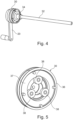
- zeigt einige Bauteile des Zugspindelaggregats aus
Fig. 2 . - Fig. 5
- zeigt ein Getriebe, das bei dem Zugspindelaggregat aus
Fig. 2 verwendet werden kann. - Fig. 6
- zeigt einige Bauteile zur Lagerung der Spindel bei dem Zugspindelaggregat aus
Fig. 2 . - In der folgenden Beschreibung werden unter Bezugnahme auf die Zeichnungen beispielhafte Ausführungsformen der vorliegenden Offenbarung beschrieben. Die Zeichnungen sind dabei nicht notwendigerweise maßstabsgetreu, sondern sollen die jeweiligen Merkmale lediglich schematisch illustrieren.
- Wie in
Fig. 1 dargestellt, umfasst ein Operationstisch 1 eine Patientenlagerfläche 2, eine Säule 3 und einen Fuß 4. Zur Durchführung von orthopädischen Operationen kann ein Extensionsholm 10 verwendet werden, mittels dessen das Bein eines Patienten P in einer gewünschten Position fixiert werden kann. Hierzu kann an einem Holm 12 des Extensionsholms 10 eine verschiebbare Strebe 14 angebracht sein, die wiederum ein Zugspindelaggregat 16 trägt, das mit einer Halterung 18 für einen Patientenfuß verbunden ist. - Wenn die verschiebbare Strebe 14 in einer geeigneten Position am Holm 12 fixiert ist, kann somit über das Zugspindelaggregat 16 Zug auf den Patientenfuß in einer Richtung entlang der Längsachse L des Zugspindelaggregats 16 ausgeübt werden, um beispielsweise ein Hüftgelenk des Patienten P auseinander zu ziehen. Der Verfahrweg des Zugspindelaggregats 16 kann hierbei bis zu 20cm betragen, um Zug auf die eingespannte Extremität auszuüben.
- Dazu wird allgemein ein Schlitten 22 des Zugspindelaggregats 16 translatorisch verfahren. Der Schlitten 22 muss dabei unter Zuglast an der eingestellten Position stehenbleiben, d.h. das Zugspindelaggregat muss selbsthemmend ausgeführt sein.
-
Fig. 2 zeigt eine Darstellung des Zugspindelaggregats 16 ausFig. 1 gemäß einer Ausführungsform der vorliegenden Offenbarung. - Das Zugspindelaggregat 16 hat ein Bedienende 11, mit welchem es der Anwender bedienen kann. Es hat ebenfalls ein Anschlussende 13 zum Anschließen eines chirurgischen Zubehörs.
- Das Zugspindelaggregat 16 ist über eine Aufnahmehülse 24 mit der verschiebbaren Strebe 14 des Extensionsholms 10 (siehe
Fig. 1 ) verbindbar. Am Anschlussende 13 kann an dem Schlitten 22 des Zugspindelaggregats 16 die Halterung 18 für einen Patientenfuß befestigt werden (sieheFig. 1 ). - Das Zugspindelaggregat 16 umfasst außerdem eine Antriebseinrichtung in Form einer Handkurbel 20, mittels derer der Schlitten 22 in Richtung der Längsachse L des Zugspindelaggregats 16 bewegbar ist.
- Zusätzlich zur Verstellung in Längsrichtung kann am Zugspindelaggregat 16 auch ein Rastmechanismus 26 vorgesehen sein, welcher eine Drehung des Schlittens 22 und der daran befestigten Fußhalterung 18 um die Längsachse L ermöglicht. Der Rastmechanismus 26 wird in der vorliegenden Beschreibung nicht detailliert ausgeführt, und ist unabhängig von der hier beschriebenen Verstellung des Schlittens 22 in Längsrichtung.
- Das Zugspindelaggregat 16 umfasst weiterhin ein Statorrohr 28, das einen Teil eines Gehäuses des Zugspindelaggregats 16 bildet und innerhalb dessen ein Gewindespindeltrieb drehbar angeordnet ist, wie nachfolgend im Einzelnen beschrieben werden wird. Weiterhin ist ein Getriebe 30 zwischen der Handkurbel 20 und dem Gewindespindeltrieb angeordnet. Vorzugsweise wird hierbei ein Planetengetriebe verwendet, so dass die Antriebsachse und die Abtriebsachse des Getriebes 30 beide auf der Längsachse L des Zugspindelaggregats liegen.
- Die
Fig. 3 und4 zeigen den Innenaufbau des Zugspindelaggregats 16 ausFig. 2 . Man erkennt den Gewindespindeltrieb 17. Dieser umfasst eine sich entlang der Längsachse L erstreckende Spindel 32, die im Statorrohr 28 drehbar aufgenommen ist. Die Spindel 32 ist dabei in einer Spindellagerhülse 34 gelagert. Bei der vorliegenden Ausführungsform ist die Spindel 32 eine Trapezspindel mit einem Durchmesser von 12mm und einer Steigung von 3mm. Damit hat die Spindel 32 ein Außengewinde, welches unter den meisten Betriebsbedingungen selbsthemmend ist. - Es ist möglich, andere Arten von Gewindespindeln, wie beispielsweise Spindeln mit Spitzgewinde oder Sägengewinde, zu verwenden.
- Der Gewindespindeltrieb 17 besitzt auch eine auf der Spindel 32 sitzende Spindelmutter 31 mit einem Innengewinde, welches mit dem Außengewinde der Spindel in Eingriff steht.
- Der Schlitten 22 ist durch eine Relativdrehung zwischen der Spindel 32 und der Spindelmutter 31 entlang der Längsachse L verfahrbar.
- Im vorliegenden Beispiel ist die Spindel 32 ortsfest und drehbar im Statorrohr 28 angeordnet und die Spindelmutter 31 drehfest und axial verschieblich mit dem Schlitten 22 verbunden. Zum Verfahren des Schlittens 22 wird die Spindel 32 gedreht, sodass sich die Spindelmutter 31 linear auf der Spindel 32 verschiebt.
- Es ist aber auch möglich, den Gewindespindeltrieb kinematisch umgekehrt auszuführen, sodass die Spindelmutter ortsfest und drehbar angeordnet ist, und die Spindel drehfest mit dem Schlitten verbunden ist. In diesem Fall verfährt die Spindel gemeinsam linear mit dem Schlitten relativ zur Spindelmutter.
- Bevorzugt besitzt das Zugspindelaggregat 16 eine zusätzliche Hemmvorrichtung 40 zur Hemmung der Relativdrehung zwischen der Spindel 32 und der Spindelmutter 31, wenn auf das Anschlussende 13 eine Zugkraft entlang der Längsachse L ausgeübt wird. Diese Hemmvorrichtung 40 weist ein Reibungspaar 41, 42 auf, wobei das Reibungspaar aus einer am Gehäuse, nämlich an der Spindellagerhülse 34, befindlichen ersten Anlagefläche 41 und einer am Gewindespindeltrieb 17 befindlichen, der ersten Anlagefläche gegenüberliegenden zweiten Anlagefläche 42 besteht. Wenn dann auf das Anschlussende 13 eine Zugkraft entlang der Längsachse L ausgeübt wird, stützt sich die zweite Anlagefläche 42 derart auf der ersten Anlagefläche 41 ab, dass ein Reibwiderstand besteht, der eine selbsttätige Relativdrehung zwischen der Spindel 32 und der Spindelmutter 31 infolge der Zugkraft unterbindet. Dieser Reibwiderstand wächst proportional zur anliegenden Axiallast an. Aus der
Fig. 3 ist ersichtlich, dass die erste und die zweite Anlagefläche 41, 42 sich im Wesentlichen senkrecht zur Längsachse L erstrecken. Die Flächen der Anlageflächen sind so bemessen, dass die Selbsthemmung mit ausreichender Sicherheit hergestellt wird. - Die zweite Anlagefläche 42 ist im vorliegenden Fall in Form einer drehfest mit der Spindel 32 verbundenen Anlagescheibe verwirklicht.
- Um mit der Handkurbel 20 den geforderten hohen Verstellweg pro Kurbelumdrehung zu generieren, ist bei der gezeigten Ausführungsform zwischen dieser und der Spindel 32 ein Planetengetriebe 30 angeordnet, das die Handkurbelumdrehung ins Schnelle übersetzt, so dass die Spindel 32 bei einer Handkurbelumdrehung z. B. etwa 3,5 Umdrehungen ausführt und somit der geforderte Verstellweg des Schlittens 22 pro Handkurbelumdrehung erreicht wird.
- Ein Beispiel für ein derartiges Planetengetriebe 30 ist in
Fig. 5 gezeigt. Hierbei ist ein Hohlrad 36 orstfest im Statorrohr 28 verschraubt, und ein Planetenträger 37 ist mit der Handkurbel 20 verbunden. Der Planetenträger 37 treibt bei dem gezeigten Beispiel drei Planetenräder 38 an, welche wiederum ein (inFig. 3 gezeigtes) im Zentrum liegendes Sonnenrad 39 antreiben, das mit der Spindel 32 verbunden ist. Die Drehachse des Planetenträgers 37, und somit die Drehachse der Handkurbel 20, fällt hierbei mit der Drehachse des Sonnenrads, und somit der Drehachse der Spindel 32, zusammen. -
Fig. 6 zeigt die Lagerung der Spindel 32 in der Spindellagerhülse 34. Dabei ist die Spindellagerhülse 34 fest am Statorrohr 28 oder an einem anderen Teil des Gehäuses des Zugspindelaggregats 16 befestigt. - Die Anlagescheibe 42 ist an der Spindel 32 befestigt und ist somit relativ zu der Spindellagerhülse 34 drehbar. Die Spindel 32 stützt sich dabei mittels der Anlagescheibe 42 in axialer Richtung entlang der Längsachse L an der Anlagefläche 41 an der Spindellagerhülse 34 ab. Die Reibkraft zwischen der Anlagescheibe 42 und der Anlagefläche 41 der Spindellagerhülse 34 ist proportional zur an der Spindel 32 anliegenden axialen Last. Der Durchmesser der Anlagescheibe 42 ist dabei ausreichend groß gewählt, sodass die Selbsthemmung des Zugspindelaggregats 16 bei allen im Betrieb zu erwartenden Zugkräften mit der erforderlichen Sicherheit erreicht wird.
- Die vorliegende Offenbarung stellt somit ein Zugspindelaggregat bereit, das selbsthemmend ist und das über einen großen Verstellweg pro Kurbelumdrehung verfügt.
- Das voranstehend beschriebene Zugspindelaggregat ermöglicht eine gute Bedienergonomie, da ein Benutzer einerseits mit relativ wenigen Umdrehungen der Handkurbel einen relativ großen Verstellweg erreichen kann, und andererseits eine Selbsthemmung der Zugspindel auch bei hohen Zugkräften sichergestellt werden kann.
- Der für die Bedienung angemessen große Verstellweg pro Handkurbelumdrehung wird durch den Einsatz des ins Schnelle übersetzende Getriebe erreicht.
- Wenn auch noch die zusätzliche Hemmvorrichtung vorgesehen ist, muss bei der Auswahl der Spindel des Gewindespindeltriebs nicht mehr darauf geachtet werden, dass diese stets selbsthemmend ist. Dadurch können Spindeln mit größerer Steigung verwendet werden. Eine größere Spindelsteigung hat den Vorteil, dass das ins Schnelle übersetzende Getriebe zur Erzielung des angemessen großen Verstellwegs ein kleineres Übersetzungsverhältnis haben kann. Es kann also ein kompaktes und einfach aufgebautes Getriebe verwendet werden.
- Im Übrigen kann das Zugspindelaggregat der vorliegenden Offenbarung auch noch die folgenden Merkmale aufweisen, welche die Selbsthemmung des Zugspindelaggregats ermöglichen:
- eine Spindel 32 mit einem Durchmesser von 25mm oder weniger, 20mm oder weniger, oder 15 mm oder weniger;
- Die Spindel hat Gewindesteigungen von 2mm oder mehr, 2,5mm oder mehr, oder 3mm oder mehr;
- Die Gewindespindel und die Spindelmutter haben derartige Abmessungen, Durchmesser und Gewindesteigungen, dass das Zugspindelaggregat nicht alleine dank deren Gewinde vollkommen selbsthemmend ist, ohne die zusätzliche Hemmvorrichtung 40. Zum Beispiel ist das Zugspindelaggregat ohne die Hemmvorrichtung 40 nicht vollkommen selbsthemmend, wenn die Gewindespindel 32 Axialkräften ausgesetzt ist, die man beim Einsatz zu erwarten hat;
- Die Hemmvorrichtung hat eine erste Fläche 41 und eine zweite Fläche 42 verschiedener Formen und Anordnungen;
- Die zwei Flächen 41 und 42 sind einander gegenüber liegend positioniert, derart, dass ein axiales Ziehen an der Spindel 32 sie zusammen drückt und Reibung zwischen den zwei Flächen 41 und 42 erzeugt. Die Reibung hemmt eine Relativdrehung zwischen den Flächen 41, 42. Die Reibung ist vorzugsweise ausreichend, um eine Drehung und eine Axialbewegung entlang des Spindelgewindes in Antwort auf ein axiales Ziehen an der Spindel 32 zu verhindern;
- Der kombinierte Widerstand der Gewindespindel 32 und der Hemmvorrichtung 40 ist notwendig, um eine Drehung und eine Axialbewegung entlang des Spindelgewindes in Antwort auf ein axiales Ziehen an der Spindel 32 zu verhindern
Claims (11)
- Selbsthemmendes Zugspindelaggregat (16) zum Einsatz bei chirurgischen Eingriffen, mit einer eine Längsachse (L) definierenden länglichen Ausdehnung, das Zugspindelaggregat umfassend:- ein Bedienende (11) zum Bedienen des Zugspindelaggregats;- ein Anschlussende (13) zum Anschließen eines chirurgischen Zubehörs an das Zugspindelaggregat;- einen Gewindespindeltrieb (17) mita) einer sich entlang der Längsachse (L) erstreckenden Spindel (32) mit einem Außengewinde; undb) einer auf der Spindel (32) sitzenden Spindelmutter (31) mit einem Innengewinde, welches mit dem Außengewinde in Eingriff steht;- einen durch eine Relativdrehung zwischen der Spindel und der Spindelmutter entlang der Längsachse verfahrbaren Schlitten (22);- eine am Bedienende (11) befindliche Antriebseinrichtung (20) zum drehenden Antreiben des Gewindespindeltriebs;dadurch gekennzeichnet, dass
das Zugspindelaggregat (16) ferner ein Getriebe (30) umfasst, das zwischen die Antriebseinrichtung (20) und den Gewindespindeltrieb (17) geschaltet ist, wobei das Getriebe dazu eingerichtet ist, eine Drehbewegung der Antriebseinrichtung (20) ins Schnelle übersetzt an den Gewindespindeltrieb (17) auszugeben, wobei sich das Zugspindelaggregat (16) durch das ins Schnelle übersetzende Getriebe (30) schnell verfahren lässt. - Zugspindelaggregat (16) nach Anspruch 1, weiterhin mit einer Hemmvorrichtung (40) zur Hemmung der Relativdrehung zwischen der Spindel und der Spindelmutter, wenn auf das Anschlussende (13) eine Zugkraft entlang der Längsachse ausgeübt wird.
- Zugspindelaggregat (16) nach Anspruch 2, ferner umfassend ein den Gewindespindeltrieb aufnehmendes Gehäuse, wobei die Hemmvorrichtung ein Reibungspaar aufweist, wobei das Reibungspaar (41, 42) aus einer am Gehäuse befindlichen ersten Anlagefläche (41) und einer am Gewindespindeltrieb befindlichen, der ersten Anlagefläche gegenüberliegenden zweiten Anlagefläche (42) besteht, wobei, wenn auf das Anschlussende (13) eine Zugkraft entlang der Längsachse (L) ausgeübt wird, die zweite Anlagefläche sich derart auf der ersten Anlagefläche abstützt, dass ein Reibwiderstand hervorgerufen wird, der eine selbsttätige Relativdrehung zwischen der Spindel (32) und der Spindelmutter (31) infolge der Zugkraft unterbindet.
- Zugspindelaggregat (16) nach Anspruch 3, wobei die erste und die zweite Anlagefläche sich im Wesentlichen senkrecht zur Längsachse erstrecken.
- Zugspindelaggregat (16) nach Anspruch 3 oder 4, wobei die Spindel ortsfest und drehbar im Gehäuse angeordnet ist und die Spindelmutter drehfest mit dem Schlitten verbunden ist, und wobei die zweite Anlagefläche an der Spindel angeordnet ist.
- Zugspindelaggregat (16) nach Anspruch 5, wobei das Gehäuse eine Spindellagerhülse (34) umfasst, an welcher die erste Anlagefläche ausgebildet ist, und wobei die Spindel (32) eine drehfest mit ihr verbundene Anlagescheibe (42) aufweist, an welcher die zweite Anlagefläche ausgebildet ist.
- Zugspindelaggregat (16) nach einem der Ansprüche 1 bis 6, wobei das Getriebe (30) ein Planetengetriebe umfasst.
- Zugspindelaggregat (16) nach einem der Ansprüche 1 bis 7, wobei das Getriebe (30) derart übersetzt ist, dass eine Umdrehung der Antriebseinrichtung (20) mindestens zwei Umdrehungen des Gewindespindeltriebs entspricht, vorzugsweise derart, dass eine Umdrehung der Antriebseinrichtung (20) 3,5 Umdrehungen des Gewindespindeltriebs entspricht.
- Zugspindelaggregat (16) nach einem der Ansprüche 1 bis 8, wobei ein Durchmesser der Spindel (32) weniger als 20mm, insbesondere weniger als 15mm beträgt.
- Zugspindelaggregat (16) nach Anspruch 9, wobei ein Durchmesser der Spindel (32) 12mm und eine Steigung der Spindel 3mm beträgt.
- Extensionsholm (10) für einen Operationstisch (1), umfassend:- einen Holm (12), welcher am Operationstisch (1) anbringbar ist;- eine verschiebbare Strebe (14), welche entlang einer Längsachse des Holms (12) verschiebbar ist, und welche eine Halterung (18) für einen Fuß eines Patienten trägt;dadurch gekennzeichnet, dass
der Extensionsholm (10) für den Operationstisch (1) ferner ein Zugspindelaggregat (16) nach einem der Ansprüche 1 bis 10 umfasst, um die Halterung (18) für den Fuß des Patienten relativ zu einer Position der Strebe (14) in einer Richtung im Wesentlichen parallel zu einer Längsachse (L) des Zugspindelaggregats (16) zu verstellen.
Applications Claiming Priority (2)
| Application Number | Priority Date | Filing Date | Title |
|---|---|---|---|
| DE102017117767.1A DE102017117767A1 (de) | 2017-08-04 | 2017-08-04 | Schnell verstellbares kompaktes Zugspindelaggregat mit Selbsthemmung zum Einsatz bei chirurgischen Eingriffen |
| PCT/EP2018/071067 WO2019025570A1 (de) | 2017-08-04 | 2018-08-02 | Schnell verstellbares kompaktes zugspindelaggregat mit selbsthemmung zum einsatz bei chirurgischen eingriffen |
Publications (2)
| Publication Number | Publication Date |
|---|---|
| EP3661472A1 EP3661472A1 (de) | 2020-06-10 |
| EP3661472B1 true EP3661472B1 (de) | 2024-09-25 |
Family
ID=63442595
Family Applications (1)
| Application Number | Title | Priority Date | Filing Date |
|---|---|---|---|
| EP18762228.7A Active EP3661472B1 (de) | 2017-08-04 | 2018-08-02 | Schnell verstellbares kompaktes zugspindelaggregat mit selbsthemmung zum einsatz bei chirurgischen eingriffen |
Country Status (7)
| Country | Link |
|---|---|
| US (1) | US12357524B2 (de) |
| EP (1) | EP3661472B1 (de) |
| JP (1) | JP2020530792A (de) |
| KR (1) | KR20200037831A (de) |
| CN (1) | CN110944615A (de) |
| DE (1) | DE102017117767A1 (de) |
| WO (1) | WO2019025570A1 (de) |
Families Citing this family (2)
| Publication number | Priority date | Publication date | Assignee | Title |
|---|---|---|---|---|
| CN111714267A (zh) * | 2020-07-10 | 2020-09-29 | 李洪彬 | 一种可拆卸术中侧卧位下肢牵引复位器 |
| CN112914938A (zh) * | 2021-02-25 | 2021-06-08 | 乔玲 | 一种麻醉患者恢复期护理肢体固定支架 |
Citations (2)
| Publication number | Priority date | Publication date | Assignee | Title |
|---|---|---|---|---|
| US20100282009A1 (en) * | 2008-01-12 | 2010-11-11 | Martin Kahr Knudsen | Linear actuator |
| DE102013202700A1 (de) * | 2012-03-12 | 2013-09-12 | Schaeffler Technologies AG & Co. KG | Planetenwälzgetriebe und Hydrostataktor mit diesem |
Family Cites Families (14)
| Publication number | Priority date | Publication date | Assignee | Title |
|---|---|---|---|---|
| US4342309A (en) * | 1981-01-08 | 1982-08-03 | Eftekhar Nas S | Bow type traction device having corporeal insertion means |
| US4747319A (en) * | 1985-12-16 | 1988-05-31 | Jidosha Kiki Co., Ltd. | Actuator |
| FR2596637B1 (fr) * | 1986-04-03 | 1988-07-15 | Marzet Aubry | Dispositif de traction pour tables d'operations et appareillages de chirurgie orthopedique |
| CN2647507Y (zh) | 2003-09-26 | 2004-10-13 | 孙希源 | 行星齿轮传动快速装置 |
| US9119610B2 (en) * | 2005-08-10 | 2015-09-01 | Joel M. Matta | Medical table having controlled movement and method of use |
| DE102006033981B4 (de) * | 2006-07-22 | 2009-02-19 | Stabilus Gmbh | Von einem Antrieb antreibbarer Spindelantrieb für ein bewegbares Bauteil |
| WO2009062545A1 (en) * | 2007-11-13 | 2009-05-22 | Schaerer Mayfield Medical Ag | Modular device for positioning and immobilisation of a patient's body for surgical operations and corresponding operating table |
| ES2395222T3 (es) * | 2008-01-12 | 2013-02-11 | Linak A/S | Dispositivo de accionamiento lineal |
| US8256047B2 (en) * | 2008-04-03 | 2012-09-04 | Klemm Kurt W | Combination treatment device and an anterior support device |
| DE202008014021U1 (de) | 2008-10-21 | 2009-02-12 | Condor Gmbh Medicaltechnik | Zug- und Drehtisch, insbesondere für die Hüft-Endoprothetik und Unfallchirurgie |
| DE202011106149U1 (de) * | 2011-09-28 | 2013-01-09 | Brose Fahrzeugteile Gmbh & Co. Kg, Hallstadt | Spindelantrieb zur motorischen Verstellung eines Verstellelements eines Kraftfahrzeugs |
| US8683631B2 (en) * | 2012-01-26 | 2014-04-01 | American Sterilizer Company | Sacral pad for a medical table |
| DE102014108745A1 (de) * | 2014-06-23 | 2015-12-24 | MAQUET GmbH | Vorrichtung zum selbsthemmenden bidirektionalen Antrieb einer medizinischen Behandlungsvorrichtung |
| US12036144B2 (en) * | 2015-05-31 | 2024-07-16 | Christopher James Brown | Surgical limb positioning and support device and method |
-
2017
- 2017-08-04 DE DE102017117767.1A patent/DE102017117767A1/de not_active Withdrawn
-
2018
- 2018-08-02 WO PCT/EP2018/071067 patent/WO2019025570A1/de not_active Ceased
- 2018-08-02 KR KR1020207006030A patent/KR20200037831A/ko not_active Withdrawn
- 2018-08-02 US US16/634,747 patent/US12357524B2/en active Active
- 2018-08-02 EP EP18762228.7A patent/EP3661472B1/de active Active
- 2018-08-02 CN CN201880048723.5A patent/CN110944615A/zh active Pending
- 2018-08-02 JP JP2020506189A patent/JP2020530792A/ja active Pending
Patent Citations (2)
| Publication number | Priority date | Publication date | Assignee | Title |
|---|---|---|---|---|
| US20100282009A1 (en) * | 2008-01-12 | 2010-11-11 | Martin Kahr Knudsen | Linear actuator |
| DE102013202700A1 (de) * | 2012-03-12 | 2013-09-12 | Schaeffler Technologies AG & Co. KG | Planetenwälzgetriebe und Hydrostataktor mit diesem |
Also Published As
| Publication number | Publication date |
|---|---|
| KR20200037831A (ko) | 2020-04-09 |
| US20200206056A1 (en) | 2020-07-02 |
| JP2020530792A (ja) | 2020-10-29 |
| CN110944615A (zh) | 2020-03-31 |
| WO2019025570A1 (de) | 2019-02-07 |
| US12357524B2 (en) | 2025-07-15 |
| DE102017117767A1 (de) | 2019-02-07 |
| EP3661472A1 (de) | 2020-06-10 |
Similar Documents
| Publication | Publication Date | Title |
|---|---|---|
| EP2504197B1 (de) | Verstellvorrichtung | |
| DE102004020982A1 (de) | Kraftgetriebenes Handwerkzeug mit Spanneinrichtung für ein Werkzeug | |
| EP1100183A2 (de) | Elektromotorische Verstelleinrichtung | |
| EP3577010B1 (de) | Motorisch verstellbare lenksäule für ein kraftfahrzeug | |
| EP2146114A2 (de) | Teleskop-Doppelspindelantrieb | |
| EP0706769A2 (de) | Vorrichtung zum Verstellen der Arbeitshöhe einer Tischplatte oder dergleichen | |
| DE3727975C2 (de) | Spielfreier Antrieb für den Zustellmechanismus eines Mikrotoms | |
| EP3472492B1 (de) | Planetengetriebe | |
| EP2949305A1 (de) | Verstelleinrichtung für eine in einer höhe verstellbare ablage sowie verfahren zum verändern einer höhe einer ablage | |
| EP2194018A2 (de) | Hebevorrichtung | |
| DE102014114779B3 (de) | Spannpatrone zur Ankopplung eines Werkzeugadapters an eine Motorspindel einer Werkzeugmaschine | |
| EP3661472B1 (de) | Schnell verstellbares kompaktes zugspindelaggregat mit selbsthemmung zum einsatz bei chirurgischen eingriffen | |
| EP1637775A1 (de) | Linearantrieb mit einer Notverstellmöglichkeit | |
| DE202019102490U1 (de) | Adapterplatte und Schnellklemmvorrichtung sowie damit versehene Anordnung bzw. Laborschwingmühle | |
| EP2886223A1 (de) | Gewinderollkopf | |
| EP3323571B1 (de) | Sägeaggregat für eine kreissäge | |
| DE102009024061B4 (de) | Maschinenreibahle | |
| EP1152167B1 (de) | Vorrichtung zum Verstellen von relativ zueinander beweglichen Teilen | |
| DE102013221349A1 (de) | Antriebseinheit | |
| DE102004056574B4 (de) | Arretiervorrichtung für ein verstellbares Anschlussteil | |
| DE102024106302B3 (de) | Verstellantrieb für eine Lenksäule eines Kraftfahrzeugs und Lenksäule für ein Kraftfahrzeug | |
| WO2005035331A1 (de) | Zusammenschiebbare lenksäulen-anordnung | |
| DE2837492A1 (de) | Feststellbremse fuer zeichenanlagen | |
| DE102005022711B3 (de) | Spannhülse zur Befestigung auf einer zylindrischen Welle oder Achse | |
| DE102016000094A1 (de) | Einspannvorrichtung zum Verspannen eines Werkstücks |
Legal Events
| Date | Code | Title | Description |
|---|---|---|---|
| STAA | Information on the status of an ep patent application or granted ep patent |
Free format text: STATUS: UNKNOWN |
|
| STAA | Information on the status of an ep patent application or granted ep patent |
Free format text: STATUS: THE INTERNATIONAL PUBLICATION HAS BEEN MADE |
|
| PUAI | Public reference made under article 153(3) epc to a published international application that has entered the european phase |
Free format text: ORIGINAL CODE: 0009012 |
|
| STAA | Information on the status of an ep patent application or granted ep patent |
Free format text: STATUS: REQUEST FOR EXAMINATION WAS MADE |
|
| 17P | Request for examination filed |
Effective date: 20200225 |
|
| AK | Designated contracting states |
Kind code of ref document: A1 Designated state(s): AL AT BE BG CH CY CZ DE DK EE ES FI FR GB GR HR HU IE IS IT LI LT LU LV MC MK MT NL NO PL PT RO RS SE SI SK SM TR |
|
| AX | Request for extension of the european patent |
Extension state: BA ME |
|
| DAV | Request for validation of the european patent (deleted) | ||
| DAX | Request for extension of the european patent (deleted) | ||
| STAA | Information on the status of an ep patent application or granted ep patent |
Free format text: STATUS: EXAMINATION IS IN PROGRESS |
|
| 17Q | First examination report despatched |
Effective date: 20221005 |
|
| GRAP | Despatch of communication of intention to grant a patent |
Free format text: ORIGINAL CODE: EPIDOSNIGR1 |
|
| STAA | Information on the status of an ep patent application or granted ep patent |
Free format text: STATUS: GRANT OF PATENT IS INTENDED |
|
| RIC1 | Information provided on ipc code assigned before grant |
Ipc: A61B 90/14 20160101ALN20240306BHEP Ipc: A61F 5/042 20060101ALN20240306BHEP Ipc: A61G 13/00 20060101ALI20240306BHEP Ipc: A61G 13/12 20060101AFI20240306BHEP |
|
| INTG | Intention to grant announced |
Effective date: 20240320 |
|
| GRAS | Grant fee paid |
Free format text: ORIGINAL CODE: EPIDOSNIGR3 |
|
| P01 | Opt-out of the competence of the unified patent court (upc) registered |
Free format text: CASE NUMBER: APP_38189/2024 Effective date: 20240627 |
|
| GRAA | (expected) grant |
Free format text: ORIGINAL CODE: 0009210 |
|
| STAA | Information on the status of an ep patent application or granted ep patent |
Free format text: STATUS: THE PATENT HAS BEEN GRANTED |
|
| AK | Designated contracting states |
Kind code of ref document: B1 Designated state(s): AL AT BE BG CH CY CZ DE DK EE ES FI FR GB GR HR HU IE IS IT LI LT LU LV MC MK MT NL NO PL PT RO RS SE SI SK SM TR |
|
| REG | Reference to a national code |
Ref country code: GB Ref legal event code: FG4D Free format text: NOT ENGLISH |
|
| REG | Reference to a national code |
Ref country code: CH Ref legal event code: EP |
|
| REG | Reference to a national code |
Ref country code: DE Ref legal event code: R096 Ref document number: 502018015173 Country of ref document: DE |
|
| REG | Reference to a national code |
Ref country code: IE Ref legal event code: FG4D Free format text: LANGUAGE OF EP DOCUMENT: GERMAN |
|
| REG | Reference to a national code |
Ref country code: LT Ref legal event code: MG9D |
|
| PG25 | Lapsed in a contracting state [announced via postgrant information from national office to epo] |
Ref country code: NO Free format text: LAPSE BECAUSE OF FAILURE TO SUBMIT A TRANSLATION OF THE DESCRIPTION OR TO PAY THE FEE WITHIN THE PRESCRIBED TIME-LIMIT Effective date: 20241225 |
|
| PG25 | Lapsed in a contracting state [announced via postgrant information from national office to epo] |
Ref country code: GR Free format text: LAPSE BECAUSE OF FAILURE TO SUBMIT A TRANSLATION OF THE DESCRIPTION OR TO PAY THE FEE WITHIN THE PRESCRIBED TIME-LIMIT Effective date: 20241226 Ref country code: FI Free format text: LAPSE BECAUSE OF FAILURE TO SUBMIT A TRANSLATION OF THE DESCRIPTION OR TO PAY THE FEE WITHIN THE PRESCRIBED TIME-LIMIT Effective date: 20240925 |
|
| PG25 | Lapsed in a contracting state [announced via postgrant information from national office to epo] |
Ref country code: BG Free format text: LAPSE BECAUSE OF FAILURE TO SUBMIT A TRANSLATION OF THE DESCRIPTION OR TO PAY THE FEE WITHIN THE PRESCRIBED TIME-LIMIT Effective date: 20240925 |
|
| PG25 | Lapsed in a contracting state [announced via postgrant information from national office to epo] |
Ref country code: LV Free format text: LAPSE BECAUSE OF FAILURE TO SUBMIT A TRANSLATION OF THE DESCRIPTION OR TO PAY THE FEE WITHIN THE PRESCRIBED TIME-LIMIT Effective date: 20240925 |
|
| PG25 | Lapsed in a contracting state [announced via postgrant information from national office to epo] |
Ref country code: RS Free format text: LAPSE BECAUSE OF FAILURE TO SUBMIT A TRANSLATION OF THE DESCRIPTION OR TO PAY THE FEE WITHIN THE PRESCRIBED TIME-LIMIT Effective date: 20241225 |
|
| REG | Reference to a national code |
Ref country code: NL Ref legal event code: MP Effective date: 20240925 |
|
| PG25 | Lapsed in a contracting state [announced via postgrant information from national office to epo] |
Ref country code: RS Free format text: LAPSE BECAUSE OF FAILURE TO SUBMIT A TRANSLATION OF THE DESCRIPTION OR TO PAY THE FEE WITHIN THE PRESCRIBED TIME-LIMIT Effective date: 20241225 Ref country code: NO Free format text: LAPSE BECAUSE OF FAILURE TO SUBMIT A TRANSLATION OF THE DESCRIPTION OR TO PAY THE FEE WITHIN THE PRESCRIBED TIME-LIMIT Effective date: 20241225 Ref country code: LV Free format text: LAPSE BECAUSE OF FAILURE TO SUBMIT A TRANSLATION OF THE DESCRIPTION OR TO PAY THE FEE WITHIN THE PRESCRIBED TIME-LIMIT Effective date: 20240925 Ref country code: GR Free format text: LAPSE BECAUSE OF FAILURE TO SUBMIT A TRANSLATION OF THE DESCRIPTION OR TO PAY THE FEE WITHIN THE PRESCRIBED TIME-LIMIT Effective date: 20241226 Ref country code: FI Free format text: LAPSE BECAUSE OF FAILURE TO SUBMIT A TRANSLATION OF THE DESCRIPTION OR TO PAY THE FEE WITHIN THE PRESCRIBED TIME-LIMIT Effective date: 20240925 Ref country code: BG Free format text: LAPSE BECAUSE OF FAILURE TO SUBMIT A TRANSLATION OF THE DESCRIPTION OR TO PAY THE FEE WITHIN THE PRESCRIBED TIME-LIMIT Effective date: 20240925 |
|
| PG25 | Lapsed in a contracting state [announced via postgrant information from national office to epo] |
Ref country code: NL Free format text: LAPSE BECAUSE OF FAILURE TO SUBMIT A TRANSLATION OF THE DESCRIPTION OR TO PAY THE FEE WITHIN THE PRESCRIBED TIME-LIMIT Effective date: 20240925 |
|
| PG25 | Lapsed in a contracting state [announced via postgrant information from national office to epo] |
Ref country code: PT Free format text: LAPSE BECAUSE OF FAILURE TO SUBMIT A TRANSLATION OF THE DESCRIPTION OR TO PAY THE FEE WITHIN THE PRESCRIBED TIME-LIMIT Effective date: 20250127 Ref country code: IS Free format text: LAPSE BECAUSE OF FAILURE TO SUBMIT A TRANSLATION OF THE DESCRIPTION OR TO PAY THE FEE WITHIN THE PRESCRIBED TIME-LIMIT Effective date: 20250125 |
|
| PG25 | Lapsed in a contracting state [announced via postgrant information from national office to epo] |
Ref country code: RO Free format text: LAPSE BECAUSE OF FAILURE TO SUBMIT A TRANSLATION OF THE DESCRIPTION OR TO PAY THE FEE WITHIN THE PRESCRIBED TIME-LIMIT Effective date: 20240925 Ref country code: SM Free format text: LAPSE BECAUSE OF FAILURE TO SUBMIT A TRANSLATION OF THE DESCRIPTION OR TO PAY THE FEE WITHIN THE PRESCRIBED TIME-LIMIT Effective date: 20240925 |
|
| PG25 | Lapsed in a contracting state [announced via postgrant information from national office to epo] |
Ref country code: ES Free format text: LAPSE BECAUSE OF FAILURE TO SUBMIT A TRANSLATION OF THE DESCRIPTION OR TO PAY THE FEE WITHIN THE PRESCRIBED TIME-LIMIT Effective date: 20240925 |
|
| PG25 | Lapsed in a contracting state [announced via postgrant information from national office to epo] |
Ref country code: EE Free format text: LAPSE BECAUSE OF FAILURE TO SUBMIT A TRANSLATION OF THE DESCRIPTION OR TO PAY THE FEE WITHIN THE PRESCRIBED TIME-LIMIT Effective date: 20240925 |
|
| PG25 | Lapsed in a contracting state [announced via postgrant information from national office to epo] |
Ref country code: CZ Free format text: LAPSE BECAUSE OF FAILURE TO SUBMIT A TRANSLATION OF THE DESCRIPTION OR TO PAY THE FEE WITHIN THE PRESCRIBED TIME-LIMIT Effective date: 20240925 Ref country code: PL Free format text: LAPSE BECAUSE OF FAILURE TO SUBMIT A TRANSLATION OF THE DESCRIPTION OR TO PAY THE FEE WITHIN THE PRESCRIBED TIME-LIMIT Effective date: 20240925 |
|
| PG25 | Lapsed in a contracting state [announced via postgrant information from national office to epo] |
Ref country code: SK Free format text: LAPSE BECAUSE OF FAILURE TO SUBMIT A TRANSLATION OF THE DESCRIPTION OR TO PAY THE FEE WITHIN THE PRESCRIBED TIME-LIMIT Effective date: 20240925 |
|
| REG | Reference to a national code |
Ref country code: DE Ref legal event code: R097 Ref document number: 502018015173 Country of ref document: DE |
|
| PG25 | Lapsed in a contracting state [announced via postgrant information from national office to epo] |
Ref country code: DK Free format text: LAPSE BECAUSE OF FAILURE TO SUBMIT A TRANSLATION OF THE DESCRIPTION OR TO PAY THE FEE WITHIN THE PRESCRIBED TIME-LIMIT Effective date: 20240925 |
|
| PLBE | No opposition filed within time limit |
Free format text: ORIGINAL CODE: 0009261 |
|
| STAA | Information on the status of an ep patent application or granted ep patent |
Free format text: STATUS: NO OPPOSITION FILED WITHIN TIME LIMIT |
|
| 26N | No opposition filed |
Effective date: 20250626 |
|
| PG25 | Lapsed in a contracting state [announced via postgrant information from national office to epo] |
Ref country code: SE Free format text: LAPSE BECAUSE OF FAILURE TO SUBMIT A TRANSLATION OF THE DESCRIPTION OR TO PAY THE FEE WITHIN THE PRESCRIBED TIME-LIMIT Effective date: 20240925 |
|
| PGFP | Annual fee paid to national office [announced via postgrant information from national office to epo] |
Ref country code: DE Payment date: 20250724 Year of fee payment: 8 |
|
| PGFP | Annual fee paid to national office [announced via postgrant information from national office to epo] |
Ref country code: IT Payment date: 20250723 Year of fee payment: 8 |
|
| PGFP | Annual fee paid to national office [announced via postgrant information from national office to epo] |
Ref country code: GB Payment date: 20250725 Year of fee payment: 8 |
|
| PGFP | Annual fee paid to national office [announced via postgrant information from national office to epo] |
Ref country code: FR Payment date: 20250723 Year of fee payment: 8 |
|
| PG25 | Lapsed in a contracting state [announced via postgrant information from national office to epo] |
Ref country code: HR Free format text: LAPSE BECAUSE OF FAILURE TO SUBMIT A TRANSLATION OF THE DESCRIPTION OR TO PAY THE FEE WITHIN THE PRESCRIBED TIME-LIMIT Effective date: 20240925 |
|
| REG | Reference to a national code |
Ref country code: CH Ref legal event code: H13 Free format text: ST27 STATUS EVENT CODE: U-0-0-H10-H13 (AS PROVIDED BY THE NATIONAL OFFICE) Effective date: 20260324 |
|
| PG25 | Lapsed in a contracting state [announced via postgrant information from national office to epo] |
Ref country code: MC Free format text: LAPSE BECAUSE OF FAILURE TO SUBMIT A TRANSLATION OF THE DESCRIPTION OR TO PAY THE FEE WITHIN THE PRESCRIBED TIME-LIMIT Effective date: 20240925 |
|
| PG25 | Lapsed in a contracting state [announced via postgrant information from national office to epo] |
Ref country code: LU Free format text: LAPSE BECAUSE OF NON-PAYMENT OF DUE FEES Effective date: 20250802 |
|
| PG25 | Lapsed in a contracting state [announced via postgrant information from national office to epo] |
Ref country code: CH Free format text: LAPSE BECAUSE OF NON-PAYMENT OF DUE FEES Effective date: 20250831 |