EP3661214A1 - Procédé et appareil de configuration de transformée pour une compression vidéo - Google Patents
Procédé et appareil de configuration de transformée pour une compression vidéo Download PDFInfo
- Publication number
- EP3661214A1 EP3661214A1 EP18842329.7A EP18842329A EP3661214A1 EP 3661214 A1 EP3661214 A1 EP 3661214A1 EP 18842329 A EP18842329 A EP 18842329A EP 3661214 A1 EP3661214 A1 EP 3661214A1
- Authority
- EP
- European Patent Office
- Prior art keywords
- transform
- amt
- vii
- inverse
- unit
- Prior art date
- Legal status (The legal status is an assumption and is not a legal conclusion. Google has not performed a legal analysis and makes no representation as to the accuracy of the status listed.)
- Granted
Links
- 238000000034 method Methods 0.000 title claims abstract description 103
- 238000007906 compression Methods 0.000 title description 3
- 230000006835 compression Effects 0.000 title description 2
- 230000003044 adaptive effect Effects 0.000 claims abstract description 19
- 230000008569 process Effects 0.000 description 31
- 238000010586 diagram Methods 0.000 description 21
- 238000013139 quantization Methods 0.000 description 19
- 101100278585 Dictyostelium discoideum dst4 gene Proteins 0.000 description 13
- 230000006870 function Effects 0.000 description 10
- 230000008859 change Effects 0.000 description 9
- 238000007781 pre-processing Methods 0.000 description 9
- 101001016186 Homo sapiens Dystonin Proteins 0.000 description 8
- 101000832669 Rattus norvegicus Probable alcohol sulfotransferase Proteins 0.000 description 8
- 238000001914 filtration Methods 0.000 description 8
- 238000012805 post-processing Methods 0.000 description 8
- 239000013074 reference sample Substances 0.000 description 8
- 239000013598 vector Substances 0.000 description 8
- 239000011159 matrix material Substances 0.000 description 7
- 238000004891 communication Methods 0.000 description 4
- 238000013461 design Methods 0.000 description 4
- 238000012545 processing Methods 0.000 description 4
- 208000037170 Delayed Emergence from Anesthesia Diseases 0.000 description 3
- 230000005540 biological transmission Effects 0.000 description 3
- 230000000903 blocking effect Effects 0.000 description 3
- 101150089388 dct-5 gene Proteins 0.000 description 3
- 230000000694 effects Effects 0.000 description 2
- 238000005516 engineering process Methods 0.000 description 2
- 238000003709 image segmentation Methods 0.000 description 2
- 102220047090 rs6152 Human genes 0.000 description 2
- 230000002123 temporal effect Effects 0.000 description 2
- 238000012549 training Methods 0.000 description 2
- 108091026890 Coding region Proteins 0.000 description 1
- 230000015572 biosynthetic process Effects 0.000 description 1
- 238000004422 calculation algorithm Methods 0.000 description 1
- 238000004364 calculation method Methods 0.000 description 1
- 239000000969 carrier Substances 0.000 description 1
- 238000004590 computer program Methods 0.000 description 1
- 238000013500 data storage Methods 0.000 description 1
- 238000000354 decomposition reaction Methods 0.000 description 1
- 239000011521 glass Substances 0.000 description 1
- 230000005055 memory storage Effects 0.000 description 1
- 238000010295 mobile communication Methods 0.000 description 1
- 238000012986 modification Methods 0.000 description 1
- 230000004048 modification Effects 0.000 description 1
- 238000012544 monitoring process Methods 0.000 description 1
- 230000003287 optical effect Effects 0.000 description 1
- 230000002093 peripheral effect Effects 0.000 description 1
- 238000003672 processing method Methods 0.000 description 1
- 230000004044 response Effects 0.000 description 1
- 230000002441 reversible effect Effects 0.000 description 1
- 239000000523 sample Substances 0.000 description 1
- 239000010454 slate Substances 0.000 description 1
- 239000004984 smart glass Substances 0.000 description 1
- 238000000638 solvent extraction Methods 0.000 description 1
- 238000003786 synthesis reaction Methods 0.000 description 1
- 230000001131 transforming effect Effects 0.000 description 1
Images


Classifications
-
- H—ELECTRICITY
- H04—ELECTRIC COMMUNICATION TECHNIQUE
- H04N—PICTORIAL COMMUNICATION, e.g. TELEVISION
- H04N19/00—Methods or arrangements for coding, decoding, compressing or decompressing digital video signals
- H04N19/10—Methods or arrangements for coding, decoding, compressing or decompressing digital video signals using adaptive coding
- H04N19/102—Methods or arrangements for coding, decoding, compressing or decompressing digital video signals using adaptive coding characterised by the element, parameter or selection affected or controlled by the adaptive coding
- H04N19/12—Selection from among a plurality of transforms or standards, e.g. selection between discrete cosine transform [DCT] and sub-band transform or selection between H.263 and H.264
- H04N19/122—Selection of transform size, e.g. 8x8 or 2x4x8 DCT; Selection of sub-band transforms of varying structure or type
-
- H—ELECTRICITY
- H04—ELECTRIC COMMUNICATION TECHNIQUE
- H04N—PICTORIAL COMMUNICATION, e.g. TELEVISION
- H04N19/00—Methods or arrangements for coding, decoding, compressing or decompressing digital video signals
- H04N19/60—Methods or arrangements for coding, decoding, compressing or decompressing digital video signals using transform coding
- H04N19/625—Methods or arrangements for coding, decoding, compressing or decompressing digital video signals using transform coding using discrete cosine transform [DCT]
-
- H—ELECTRICITY
- H04—ELECTRIC COMMUNICATION TECHNIQUE
- H04N—PICTORIAL COMMUNICATION, e.g. TELEVISION
- H04N19/00—Methods or arrangements for coding, decoding, compressing or decompressing digital video signals
- H04N19/10—Methods or arrangements for coding, decoding, compressing or decompressing digital video signals using adaptive coding
- H04N19/134—Methods or arrangements for coding, decoding, compressing or decompressing digital video signals using adaptive coding characterised by the element, parameter or criterion affecting or controlling the adaptive coding
- H04N19/157—Assigned coding mode, i.e. the coding mode being predefined or preselected to be further used for selection of another element or parameter
- H04N19/159—Prediction type, e.g. intra-frame, inter-frame or bidirectional frame prediction
-
- H—ELECTRICITY
- H04—ELECTRIC COMMUNICATION TECHNIQUE
- H04N—PICTORIAL COMMUNICATION, e.g. TELEVISION
- H04N19/00—Methods or arrangements for coding, decoding, compressing or decompressing digital video signals
- H04N19/10—Methods or arrangements for coding, decoding, compressing or decompressing digital video signals using adaptive coding
- H04N19/169—Methods or arrangements for coding, decoding, compressing or decompressing digital video signals using adaptive coding characterised by the coding unit, i.e. the structural portion or semantic portion of the video signal being the object or the subject of the adaptive coding
- H04N19/18—Methods or arrangements for coding, decoding, compressing or decompressing digital video signals using adaptive coding characterised by the coding unit, i.e. the structural portion or semantic portion of the video signal being the object or the subject of the adaptive coding the unit being a set of transform coefficients
-
- H—ELECTRICITY
- H04—ELECTRIC COMMUNICATION TECHNIQUE
- H04N—PICTORIAL COMMUNICATION, e.g. TELEVISION
- H04N19/00—Methods or arrangements for coding, decoding, compressing or decompressing digital video signals
- H04N19/46—Embedding additional information in the video signal during the compression process
- H04N19/463—Embedding additional information in the video signal during the compression process by compressing encoding parameters before transmission
-
- H—ELECTRICITY
- H04—ELECTRIC COMMUNICATION TECHNIQUE
- H04N—PICTORIAL COMMUNICATION, e.g. TELEVISION
- H04N19/00—Methods or arrangements for coding, decoding, compressing or decompressing digital video signals
- H04N19/60—Methods or arrangements for coding, decoding, compressing or decompressing digital video signals using transform coding
- H04N19/61—Methods or arrangements for coding, decoding, compressing or decompressing digital video signals using transform coding in combination with predictive coding
-
- H—ELECTRICITY
- H04—ELECTRIC COMMUNICATION TECHNIQUE
- H04N—PICTORIAL COMMUNICATION, e.g. TELEVISION
- H04N19/00—Methods or arrangements for coding, decoding, compressing or decompressing digital video signals
- H04N19/70—Methods or arrangements for coding, decoding, compressing or decompressing digital video signals characterised by syntax aspects related to video coding, e.g. related to compression standards
-
- H—ELECTRICITY
- H04—ELECTRIC COMMUNICATION TECHNIQUE
- H04N—PICTORIAL COMMUNICATION, e.g. TELEVISION
- H04N19/00—Methods or arrangements for coding, decoding, compressing or decompressing digital video signals
- H04N19/10—Methods or arrangements for coding, decoding, compressing or decompressing digital video signals using adaptive coding
- H04N19/169—Methods or arrangements for coding, decoding, compressing or decompressing digital video signals using adaptive coding characterised by the coding unit, i.e. the structural portion or semantic portion of the video signal being the object or the subject of the adaptive coding
- H04N19/17—Methods or arrangements for coding, decoding, compressing or decompressing digital video signals using adaptive coding characterised by the coding unit, i.e. the structural portion or semantic portion of the video signal being the object or the subject of the adaptive coding the unit being an image region, e.g. an object
- H04N19/176—Methods or arrangements for coding, decoding, compressing or decompressing digital video signals using adaptive coding characterised by the coding unit, i.e. the structural portion or semantic portion of the video signal being the object or the subject of the adaptive coding the unit being an image region, e.g. an object the region being a block, e.g. a macroblock
-
- H—ELECTRICITY
- H04—ELECTRIC COMMUNICATION TECHNIQUE
- H04N—PICTORIAL COMMUNICATION, e.g. TELEVISION
- H04N19/00—Methods or arrangements for coding, decoding, compressing or decompressing digital video signals
- H04N19/90—Methods or arrangements for coding, decoding, compressing or decompressing digital video signals using coding techniques not provided for in groups H04N19/10-H04N19/85, e.g. fractals
- H04N19/91—Entropy coding, e.g. variable length coding [VLC] or arithmetic coding
Definitions
- the present disclosure relates to a method and apparatus for processing a video signal and, more particularly, to a technology for configuring a transform combination for each transform configuration group distinguished based on at least one of a prediction mode, a block size or a block shape.
- Next-generation video content will have characteristics of a high spatial resolution, a high frame rate, and high dimensionality of scene representation.
- technologies such as memory storage, a memory access rate, and processing power, will be remarkably increased.
- the disclosure is to design a more efficient transform configuration in terms of coding efficiency and complexity.
- the disclosure is to propose a method of configuring a transform combination for each transform configuration group distinguished based on at least one of a prediction mode, a block size or a block shape.
- the disclosure is to propose an encoder/decoder structure for incorporating a new transform design.
- the disclosure provides a method of substituting discrete cosine transform type 8 (DCT8) with a modified form of discrete sine transform type 7 (DST7) while using kernel coefficient data of the DST7 without any change.
- DCT8 discrete cosine transform type 8
- DST7 modified form of discrete sine transform type 7
- the disclosure provides a method of substituting DST7 with DST4 and substituting DCT8 with a modified form of DCT4 while using kernel coefficient data of the DST4 without any change.
- the disclosure provides a method of configuring transform configuration groups based on at least one of a prediction mode, a block size or a block shape and differently configuring a transform corresponding to each row or column, wherein one transform configuration group is configured with one or more transform combinations and one transform combination is configured with transforms corresponding to all rows and columns.
- the disclosure provides a method of configuring transforms for all rows and columns based on one transform, such as DST7 or DST4, and a transform modified therefrom.
- the disclosure provides a method of configuring a transform set which may be derived with respect to all transforms in such a way as to use linear relations between all trigonometric transforms (8 DCTs, 8 DSTs) or adding a post/pre-processing process to a transform input/output part, computing a union of the derived transform sets, and using the union to determine a transform combination.
- the disclosure can generate transform coefficients having higher coding efficiency by configuring transforms for all rows and columns for each transform configuration group based on a predetermined number of transforms when a still image or a moving image is coded.
- the disclosure provides a method of decoding a video signal based on adaptive multiple transforms (AMT), including obtaining an AMT index from the video signal, wherein the AMT index indicates any one of a plurality of transform combinations within a transform configuration group, and the transform configuration group includes discrete sine transform type 7 (DST7) and discrete cosine transform type 8 (DCT8), deriving a transform combination corresponding to the AMT index, wherein the transform combination is configured with a horizontal transform and a vertical transform and includes at least one of the DST-7 or the DCT-8, performing an inverse transform on a current block based on the transform combination, and reconstructing the video signal using the inverse-transformed current block, wherein the AMT indicates a transform method performed based on a transform combination adaptively selected from the plurality of transform combinations.
- AMT adaptive multiple transforms
- the transform configuration group is configured based on at least one of a prediction mode, block size or block shape of the current block.
- the inverse transform is applied only when both a width and height of a transform unit are 32 or less.
- the method further includes obtaining an AMT flag from the video signal, wherein the AMT flag indicates whether the AMT is performed, and wherein the AMT index is obtained when an AMT is performed based on the AMT flag.
- the method further includes checking whether the number of non-zero transform coefficient is greater than a threshold if an AMT is performed based on the AMT flag, wherein the AMT index is obtained when the number of non-zero transform coefficient is greater than the threshold.
- performing the inverse transform includes applying an inverse transform of the DST-7 or an inverse transform of the DCT-8 to each row after applying the inverse transform of the DST-7 or the inverse transform of the DCT-8 to each column if the vertical transform or the horizontal transform is the DST-7 or DCT-8.
- the vertical transform or the horizontal transform is differently applied to each row and/or each column.
- an AMT flag or the AMT index is defined in at least one level of a sequence, a picture, a slice, a block, a coding unit, a transform unit or a prediction unit.
- the disclosure provides an apparatus for decoding a video signal based on adaptive multiple transforms (AMT), including a parsing unit configured to parse an AMT index from the video signal, wherein the AMT index indicates any one of a plurality of transform combinations within a transform configuration group, and the transform configuration group includes discrete sine transform type 7 (DST7) and discrete cosine transform type 8 (DCT8), a inverse transform unit configured to derive a transform combination corresponding to the AMT index and perform an inverse transform on a current block based on the transform combination, and a reconstruction unit configured to reconstruct the video signal using the inverse-transformed current block.
- the AMT indicates a transform method performed based on a transform combination adaptively selected from the plurality of transform combinations.
- the transform combination is configured with a horizontal transform and a vertical transform and includes at least one of the DST-7 or the DCT-8.
- the parsing unit is configured to further parse, from the video signal, an AMT flag indicating whether an AMT is performed, and the AMT index is obtained when an AMT is performed based on the AMT flag.
- the inverse transform unit is configured to further check whether a number of non-zero transform coefficient is greater than a threshold if an AMT is performed based on the AMT flag, and the AMT index is obtained when the number of non-zero transform coefficient is greater than the threshold.
- the inverse transform unit is configured to apply an inverse transform of the DST-7 or an inverse transform of the DCT-8 to each row after applying the inverse transform of the DST-7 or the inverse transform of the DCT-8 to each column if the vertical transform or the horizontal transform is the DST-7 or DCT-8.
- FIG. 1 shows a schematic block diagram of an encoder for encoding a video signal, in accordance with one embodiment of the present invention.
- the encoder 100 may include an image segmentation unit 110, a transform unit 120, a quantization unit 130, a dequantization unit 140, an inverse transform unit 150, a filtering unit 160, a decoded picture buffer (DPB) 170, an inter-prediction unit 180, an intra-predictor 185 and an entropy encoding unit 190.
- an image segmentation unit 110 a transform unit 120, a quantization unit 130, a dequantization unit 140, an inverse transform unit 150, a filtering unit 160, a decoded picture buffer (DPB) 170, an inter-prediction unit 180, an intra-predictor 185 and an entropy encoding unit 190.
- DPB decoded picture buffer
- the image segmentation unit 110 may segment an input image (or a picture or frame), input to the encoder 100, into one or more processing units.
- the process unit may be a coding tree unit (CTU), a coding unit (CU), a prediction unit (PU), or a transform unit (TU).
- CTU coding tree unit
- CU coding unit
- PU prediction unit
- TU transform unit
- coding unit is employed as a unit used in a process of encoding or decoding a video signal, however, the present invention is not limited thereto, another process unit may be appropriately selected based on contents of the present disclosure.
- the encoder 100 may generate a residual signal by subtracting a prediction signal output from the inter prediction unit 180 or intra prediction unit 185 from the input image signal.
- the generated residual signal may be transmitted to the transform unit 120.
- the transform unit 120 may generate a transform coefficient by applying a transform scheme to a residual signal.
- the transform process may be applied a block (square or rectangle) split by a square block of a quadtree structure or a binarytree structure, a ternary structure or an asymmetric structure.
- the transform unit 120 may perform a transform based on a plurality of transforms (or transform combinations). Such a transform method may be called an enhanced multiple transform (EMT).
- EMT may be referred to as an adaptive multiple transform (AMT) or a multiple transform selection (MTS).
- AMT adaptive multiple transform
- MTS multiple transform selection
- the EMT may mean a transform method performed based on transform (or transform combinations) adaptively selected from a plurality of transforms (or transform combinations).
- the plurality of transforms may include transform (or transform combinations) described in FIGS. 6 and 12 to 17 of the disclosure.
- the transform or the transform type may be indicated like DCT-Type 2, DCT-II, DCT-2 or DCT2, for example.
- the transform unit 120 may perform the following embodiments.
- the disclosure provides a method of substituting discrete cosine transform type 8 (DCT8) with a modified form of discrete sine transform type 7 (DST7) while using kernel coefficient data of the DST7 without any change.
- DCT8 discrete cosine transform type 8
- DST7 modified form of discrete sine transform type 7
- the disclosure provides a method of substituting DST7 with DST4 and substituting DCT8 with a modified form of DCT4 while using kernel coefficient data of the DST4 without any change.
- the disclosure provides a method of configuring transform configuration groups based on at least one of a prediction mode, a block size or a block shape and differently configuring a transform corresponding to each row or column, wherein one transform configuration group is configured with one or more transform combinations and one transform combination is configured with transforms corresponding to all rows and columns.
- the disclosure provides a method of configuring transforms for all rows and columns based on one transform, such as DST7 or DST4, and a transform modified therefrom.
- the disclosure provides a method of configuring a transform set which may be derived with respect to all transforms in such a way as to use linear relations between all trigonometric transforms (8 DCTs, 8 DSTs) or adding a post/pre-processing process to a transform input/output part, computing a union of the derived transform sets, and using the union to determine a transform combination.
- the quantization unit 130 may quantize a transform coefficient and transmit it to the entropy encoding unit 190.
- the entropy encoding unit 190 may entropy-code a quantized signal and output it as a bitstream.
- the transform unit 120 and the quantization unit 130 are described as separate function units, but the disclosure is not limited thereto.
- the transform unit 120 and the quantization unit 130 may be combined into a single function unit.
- the dequantization unit 140 and the transform unit 150 may be combined into a single function unit.
- the quantized signal output by the quantization unit 130 may be used to generate a prediction signal.
- a residual signal may be reconstructed by applying dequantization and an inverse transform to the quantized signal through the dequantization unit 140 and the transform unit 150 within a loop.
- a reconstructed signal may be generated by adding the reconstructed residual signal to a prediction signal output by the inter prediction unit 180 or the intra prediction unit 185.
- an artifact in which a block boundary appears may occur due to a quantization error occurring in such a compression process.
- a blocking artifact which is one of important factors in evaluating picture quality.
- a filtering process may be performed. Picture quality can be improved by reducing an error of a current picture while removing a blocking artifact through such a filtering process.
- the filtering unit 160 may apply filtering to the reconstructed signal and then outputs the filtered reconstructed signal to a reproducing device or the decoded picture buffer 170.
- the filtered signal transmitted to the decoded picture buffer 170 may be used as a reference picture in the inter-prediction unit 180. In this way, using the filtered picture as the reference picture in the inter-picture prediction mode, not only the picture quality but also the coding efficiency may be improved.
- the decoded picture buffer 170 may store the filtered picture for use as the reference picture in the inter-prediction unit 180.
- the inter-prediction unit 180 may perform a temporal prediction and/or a spatial prediction on the reconstructed picture in order to remove temporal redundancy and/or spatial redundancy.
- the reference picture used for the prediction may be a transformed signal obtained via the quantization and dequantization on a block basis in the previous encoding/decoding. Thus, this may result in blocking artifacts or ringing artifacts.
- the inter-prediction unit 180 may interpolate signals between pixels on a subpixel basis using a low-pass filter.
- the subpixel may mean a virtual pixel generated by applying an interpolation filter.
- An integer pixel means an actual pixel existing in a reconstructed picture.
- An interpolation method may include linear interpolation, bi-linear interpolation, a Wiener filter, etc.
- the interpolation filter is applied to a reconstructed picture, and thus can improve the precision of a prediction.
- the inter prediction unit 180 may generate an interpolated pixel by applying the interpolation filter to an integer pixel, and may perform a prediction using an interpolated block configured with interpolated pixels as a prediction block.
- the intra prediction unit 185 may predict a current block with reference to samples peripheral to a block to be now encoded.
- the intra prediction unit 185 may perform the following process in order to perform intra prediction.
- the prediction unit may prepare a reference sample necessary to generate a prediction signal.
- the prediction unit may generate a prediction signal using the prepared reference sample.
- the prediction unit encodes a prediction mode.
- the reference sample may be prepared through reference sample padding and/or reference sample filtering.
- the reference sample may include a quantization error because a prediction and reconstruction process has been performed on the reference sample. Accordingly, in order to reduce such an error, a reference sample filtering process may be performed on each prediction mode used for intra prediction.
- the prediction signal generated through the inter prediction unit 180 or the intra prediction unit 185 may be used to generate a reconstructed signal or may be used to generate a residual signal.
- FIG. 2 is a block diagram illustrating the configuration of a decoder for decoding a video signal according to an embodiment of the present invention.
- the decoder 200 may be configured to include a parsing unit (not illustrated), an entropy decoding unit 210, a dequantization unit 220, a transform unit 230, a filter 240, a decoded picture buffer (DPB) 250, an inter prediction unit 260 and an intra prediction unit 265.
- a reconstructed image signal output through the decoder 200 may be played back through a playback device.
- the decoder 200 may receive a signal output by the encoder 100 of FIG. 1 .
- the received signal may be entropy-decoded through the entropy decoding unit 210.
- the dequantization unit 220 obtains a transform coefficient from the entropy-decoded signal using quantization step size information.
- the transform unit 230 obtains a residual signal by inverse-transforming the transform coefficient.
- the disclosure provides a method of configuring a transform combination for each transform configuration group distinguished based on at least one of a prediction mode, a block size or a block shape.
- the transform unit 230 may perform an inverse transform based on a transform combination configured by the disclosure. Furthermore, embodiments described in the disclosure may be applied.
- the dequantization unit 220 and the transform unit 230 are described as separate function units, but the disclosure is not limited thereto.
- the dequantization unit 220 and the transform unit 230 may be combined into a single function unit.
- a reconstructed signal is generated by adding the obtained residual signal to a prediction signal output by the inter prediction unit 260 or the intra prediction unit 265.
- the filter 240 may output or transmit the reconstructed signal to a playback device or the decoded picture buffer unit 250 by applying filtering to the reconstructed signal.
- the filtered signal transmitted to the decoded picture buffer unit 250 may be used as a reference picture in the inter prediction unit 260.
- each function unit of the encoder 100 may be identically applied to the transform unit 230 and corresponding function unit of the decoder.
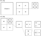
- FIG. 3 illustrates embodiments to which the disclosure may be applied
- FIG. 3A is a diagram for describing a block split structure based on a quadtree (hereinafter referred to as a "QT")
- FIG. 3B is a diagram for describing a block split structure based on a binary tree (hereinafter referred to as a "BT")
- FIG. 3C is a diagram for describing a block split structure based on a ternary tree (hereinafter referred to as a "TT”)
- FIG. 3D is a diagram for describing a block split structure based on an asymmetric tree (hereinafter referred to as an "AT").
- one block may be split based on a quadtree (QT). Furthermore, one subblock split by the QT may be further split recursively using the QT.
- a leaf block that is no longer QT split may be split using at least one method of a binary tree (BT), a ternary tree (TT) or an asymmetric tree (AT).
- the BT may have two types of splits of a horizontal BT (2NxN, 2NxN) and a vertical BT (Nx2N, Nx2N).
- the TT may have two types of splits of a horizontal TT (2Nx1/2N, 2NxN, 2Nx1/2N) and a vertical TT (1/2Nx2N, Nx2N, 1/2Nx2N).
- the AT may have four types of splits of a horizontal-up AT (2Nx1/2N, 2Nx3/2N), a horizontal-down AT (2Nx3/2N, 2Nx1/2N), a vertical-left AT (1/2Nx2N, 3/2Nx2N), and a vertical-right AT (3/2Nx2N, 1/2Nx2N).
- Each BT, TT, or AT may be further split recursively using the BT, TT, or AT.
- FIG. 3A shows an example of a QT split.
- a block A may be split into four subblocks A0, A1, A2, and A3 by a QT.
- the subblock A1 may be split into four subblocks B0, B1, B2, and B3 by a QT.
- FIG. 3B shows an example of a BT split.
- a block B3 that is no longer split by a QT may be split into vertical BTs C0 and C1 or horizontal BTs D0 and D1.
- each subblock may be further split recursively like the form of horizontal BTs E0 and E1 or vertical BTs F0 and F1.
- FIG. 3C shows an example of a TT split.
- a block B3 that is no longer split by a QT may be split into vertical TTs C0, C1, and C2 or horizontal TTs D0, D1, and D2.
- each subblock may be further split recursively like the form of horizontal TTs E0, E1, and E2 or vertical TTs F0, F1, and F2.
- FIG. 3D shows an example of an AT split.
- a block B3 that is no longer split by a QT may be split into vertical ATs C0 and C1 or horizontal ATs D0 and D1.
- each subblock may be further split recursively like the form of horizontal ATs E0 and E1 or vertical TTs F0 and F1.
- BT, TT, and AT splits may be split together.
- a subblock split by a BT may be split by a TT or AT.
- a subblock split by a TT may be split by a BT or AT.
- a subblock split by an AT may be split by a BT or TT.
- each subblock may be split into vertical BTs or after a vertical BT split, each subblock may be split into horizontal BTs.
- the two types of split methods are different in a split sequence, but have the same finally split shape.
- the sequence that the block is searched may be defined in various ways. In general, the search is performed from left to right or from top to bottom.
- To search a block may mean a sequence for determining whether to split an additional block of each split subblock or may mean a coding sequence of each subblock if a block is no longer split or may mean a search sequence when information of another neighbor block is referred in a subblock.
- FIGS. 4 and 5 are embodiments to which the disclosure is applied.
- FIG. 4 illustrates a schematic block diagram of a transform and quantization unit 120/130 and a dequantization and transform unit 140/150 within the encoder
- FIG. 5 illustrates a schematic block diagram of a dequantization and transform unit 220/230 within the decoder.
- the transform and quantization unit 120/130 may include a primary transform unit 121, a secondary transform unit 122 and the quantization unit 130.
- the dequantization and transform unit 140/150 may include the dequantization unit 140, an inverse secondary transform unit 151 and an inverse primary transform unit 152.
- the dequantization and transform unit 220/230 may include the dequantization unit 220, an inverse secondary transform unit 231 and an inverse primary transform unit 232.
- the transform when a transform is performed, the transform may be performed through a plurality of steps. For example, as in FIG. 4 , two steps of a primary transform and a secondary transform may be applied or more transform steps may be used according to an algorithm.
- the primary transform may be referred to as a core transform.
- the primary transform unit 121 may apply a primary transform on a residual signal.
- the primary transform may be pre-defined in a table form in the encoder and/or the decoder.
- a discrete cosine transform type 2 (hereinafter “DCT2”) may be applied to the primary transform.
- a discrete sine transform-type 7 (hereinafter called “DST7”) may be applied to a specific case.
- the DST7 may be applied to a 4x4 block.
- combinations of several transforms (DST 7, DCT 8, DST 1, and DCT 5) of the adaptive multiple transforms (AMT) may be applied to the primary transform.
- FIG. 6 may be applied.
- the secondary transform unit 122 may apply a secondary transform to the primary transformed signal.
- the secondary transform may be pre-defined in a table form in the encoder and/or the decoder.
- a non-separable secondary transform (hereinafter “NSST”) may be conditionally applied to the secondary transform.
- the NSST is applied to only an intra prediction block, and may have a transform set which may be applied to each prediction mode group.
- the prediction mode group may be configured based on symmetry for a prediction direction.
- a prediction mode 52 and a prediction mode 16 are symmetrical with respect to a prediction mode 34 (diagonal direction), and may form a single group. Accordingly, the same transform set may be applied to the single group.
- a transform for the prediction mode 52 when applied, it is applied after input data is transposed. The reason for this is that the transform set for the prediction mode 16 is the same as that for the prediction mode 52.
- the planar mode and the DC mode have respective transform set because symmetry for direction is not present, the respective transform set may be configured with two transforms.
- the remaining directional mode may be configured with three transforms for each transform set.
- the NSST is not applied to whole area of primary transformed block, but may be applied to only a top left 8x8 area. For example, if the size of a block is 8x8 or more, an 8x8 NSST is applied. If the size of a block is less than 8x8, a 4x4 NSST is applied, in this case, after the block is split into 4x4 blocks, a 4x4 NSST is applied to each of the blocks.
- the quantization unit 130 may perform quantization on the secondary transformed signal.
- the dequantization and transform unit 140/150 inversely performs the aforementioned process, and a redundant description thereof is omitted.
- FIG. 5 illustrates a schematic block diagram of a dequantization and transform unit 220/230 within the decoder.
- the dequantization and transform unit 220/230 may include the dequantization unit 220, an inverse secondary transform unit 231 and an inverse primary transform unit 232.
- the dequantization unit 220 obtains a transform coefficient from an entropy-decoded signal using quantization step size information.
- the inverse secondary transform unit 231 performs an inverse secondary transform on the transform coefficient.
- the inverse secondary transform indicates an inverse transform of the secondary transform described in FIG. 4 .
- the inverse primary transform unit 232 performs an inverse primary transform on the inverse secondary transformed signal (or block), and obtains a residual signal.
- the inverse primary transform indicates an inverse transform of the primary transform described in FIG. 4 .
- the disclosure provides a method of configuring a transform combination for each transform configuration group distinguished by at least one of a prediction mode, a block size or a block shape.
- the inverse primary transform unit 232 may perform an inverse transform based on a transform combination configured by the disclosure. Furthermore, embodiments described in the disclosure may be applied.
- FIG. 6 is an embodiment to which the disclosure is applied and is a table illustrating a transform configuration group to which adaptive multiple transforms (AMT) is applied.
- AMT adaptive multiple transforms
- an j-th transform combination candidate for a transform configuration group Gi is indicated in pairs, such as Equation 1.
- H(G i , j) indicates a horizontal transform for an j-th candidate
- V(G i , j) indicates a vertical transform for the j-th candidate.
- H(G 3 , 2) DST7
- a value assigned to H(G i , j) or V(G i , j) may be a nominal value for distinguishment between transforms as in the example or may be an index value indicating a corresponding transform or may be a 2-dimensional matrix (2D matrix) for a corresponding transform.
- 2D matrix values for a DCT and a DST may be indicated like Equations 2 to 3.
- DCT type 2 C N II
- DCT type 8 C N VIII
- DST type 7 S N VII
- DST type 4 S N IV
- a transform is a DST or a DCT is indicated as S or C
- a type number is indicated as a superscript in the form of a Roman number
- N of a subscript indicates an NxN transform.
- column vectors form a transform basis.
- transform configuration groups may be determined based on a prediction mode, and the number of groups may be a total of 6 G0 ⁇ G5. Furthermore, G0 ⁇ G4 corresponds to a case where an intra prediction is applied, and G5 indicates transform combinations (or transform set, the transform combination set) applied to a residual block generated by an inter prediction.
- One transform combination may be configured with a horizontal transform (or row transform) applied to the rows of a corresponding 2D block and a vertical transform (or column transform) applied to the columns of the corresponding 2D block.
- each of the transform configuration groups may have four transform combination candidates.
- the four transform combination candidates may be selected or determined through transform combination indices 0 ⁇ 3.
- the encoder may encode a transform combination index and transmit it to the decoder.
- residual data (or a residual signal) obtained through an intra prediction may have different statistical characteristics depending on its intra prediction mode. Accordingly, as in FIG. 6 , other transforms not a common cosine transform may be applied for each intra prediction mode.
- FIG. 6 illustrates a case where 35 intra prediction modes are used and a case where 67 intra prediction modes are used.
- a plurality of transform combinations may be applied to each transform configuration group distinguished in an intra prediction mode column.
- the plurality of transform combinations may be configured with four (row direction transform and column direction transform) combinations.
- a total of four combinations are available because DST-7 and DCT-5 can be applied to both a row (horizontal) direction and a column (vertical) direction.
- a transform combination index for selecting one of the four transform kernel combinations may be transmitted for each transform unit.
- the transform combination index may be called an AMT index and may be represented as amt_idx.
- a transform may be adaptively performed by defining an AMT flag for each coding unit. In this case, when the AMT flag is 0, DCT-2 may be applied to both the row direction and the column direction. When the AMT flag is 1, one of the four combinations may be selected or determined through an AMT index.
- DST-7 when the AMT flag is 1, if the number of non-zero transform coefficient for one transform unit is not greater than a threshold, DST-7 may be applied to both the row direction and the column direction without applying the transform kernels of FIG. 6 .
- the threshold may be set to 2, which may be differently set based on the size of a block size or transform unit. This may also be applied to other embodiments of the disclosure.
- transform coefficient values can be first parsed. If the number of non-zero transform coefficient is not greater than the threshold, an AMT index is not parsed and DST-7 is applied, thereby being capable of reducing the amount of additional information transmitted.
- the AMT flag is 1, if the number of non-zero transform coefficient for one transform unit is greater than the threshold, an AMT index is parsed, and a horizontal transform and a vertical transform may be determined based on the AMT index.
- an AMT may be applied to a case where both the width and height of a transform unit is 32 or less.
- FIG. 6 may be present through off-line training.
- the AMT index may be defined as one index capable of indicating a combination of a horizontal transform and a vertical transform.
- the AMT index may separately define a horizontal transform index and a vertical transform index.
- the AMT flag or the AMT index may be defined in at least one level of a sequence, a picture, a slice, a block, a coding unit, a transform unit or a prediction unit.
- the AMT flag or the AMT index may be defined in at least one of a sequence parameter set (SPS) or a transform unit.
- SPS sequence parameter set
- C N VIII and S N VII satisfy a relation equation of Equation 4.
- C N VIII J N S N VII D N
- Equation 4 J N is a matrix having a value of 1 only in a reverse diagonal line, and D N is a matrix in which 1 and -1 alternately appear only in a diagonal line.
- a subscript A is an abbreviation of alternate and indicates that a sign is alternately changed.
- a subscript R means that order of vectors is changed, and a subscript AR means that the two cases are applied.
- Equation 5 If the equation is deployed as in Equation 5 by applying Equation 4, a separate memory space for storing C N VIII is not necessary within a codec because a transform for C N VIII can be applied using only transform base vectors forming S N VII .
- Equation 5 when a forward transform for C N VIII is applied, x R may be calculated and S N VII , A T may be multiplied or S N VII , AR T may be multiplied without changing x . Furthermore, when S N VII , A T and S N VII , AR T are applied, sign inversion is not applied to the base vectors themselves forming S N VII , but as in Equation 6, an inner product may be calculated by applying sign inversion to x R when each base vector and an inner product for x are calculated.
- Equations 5 and 6 propose a method of obviating a memory necessary to store C N VIII by representing C N VIII as kernel coefficient data of S N VII .
- C N VIII , F may be used instead of C N VIII as in Equation 7 without applying the relation equation of Equation 4 without any change.
- C N VIII , F indicates flipped DST7. If C N VIII , F is used as in Equation 7, this is the same as that S N VII is applied to x R instead of x . Accordingly, it is not necessary to alternately apply sign inversion as in Equations 5 and 6.
- a backward (inverse) transform application method corresponding to Equation 5 is the same as Equation 8
- a backward (inverse) transform application method corresponding to Equation 7 is the same as Equation 9.
- DCT4 may be represented as DST4 using Equation 10. Accordingly, a separate memory space for storing DCT4 is not necessary.
- a method of applying a forward transform to DCT4 using the same method as Equation 5 is described like Equation 11.
- Equation 12 As in Equation 6, the same results as Equation 11 can be obtained without any modification for kernel coefficient data of S N IV by properly taking sign inversion for x R .
- Equation 13 sign inversion may be obviated using C N IV , F instead of C N IV using the same method as Equation 7.
- a backward (inverse) transform application method corresponding to Equation 11 is the same as Equation 14, and a backward (inverse) transform application method corresponding to Equation 13 is the same as Equation 15.
- FIG. 7 is an embodiment to which the disclosure is applied and is a flowchart illustrating an encoding process on which adaptive multiple transforms (AMT) is performed.
- AMT adaptive multiple transforms
- transforms are separately applied to a horizontal direction and a vertical direction
- a transform combination may be configured with non-separable transforms.
- separable transforms and non-separable transforms may be mixed and configured.
- selecting transform for each row/column or for each horizontal/vertical direction is not necessary, and the transform combinations of FIG. 6 may be used only when separable transforms are selected.
- the methods proposed in the disclosure may be applied regardless of a primary transform or a secondary transform. That is, there is not limit that the methods must be applied to only any one of a primary transform or a secondary transform and may be applied to both.
- the primary transform may mean a transform for first transforming a residual block
- the secondary transform may mean a transform for applying a transform to a block generated as the results of the primary transform.
- the encoder may determine a transform configuration group corresponding to a current block (S710).
- the transform configuration group may mean the transform configuration group of FIG. 6 , but the disclosure is not limited thereto.
- the transform configuration group may be configured with other transform combinations.
- the encoder may perform a transform on available candidate transform combinations within the transform configuration group (S720).
- the encoder may determine or select a transform combination having the smallest rate distortion (RD) cost based on a result of the execution of the transform (S730).
- RD rate distortion
- the encoder may encode a transform combination index corresponding to the selected transform combination (S740).
- FIG. 8 is an embodiment to which the disclosure is applied and is a flowchart illustrating a decoding process on which adaptive multiple transforms (AMT) is performed.
- AMT adaptive multiple transforms
- the decoder may determine a transform configuration group for a current block (S810).
- the decoder may parse (or obtain) a transform combination index from a video signal.
- the transform combination index may correspond to any one of a plurality of transform combinations within the transform configuration group (S820).
- the transform configuration group may include discrete sine transform type 7 (DST7) and discrete cosine transform type 8 (DCT8).
- the transform combination index may be called an AMT index.
- the transform configuration group may be configured based on at least one of a prediction mode, block size or block shape of a current block.
- the decoder may derive a transform combination corresponding to the transform combination index (S830).
- the transform combination is configured with a horizontal transform and a vertical transform, and may include at least one of the DST-7 or the DCT-8.
- the transform combination may mean the transform combination described in FIG. 6 , but the disclosure is not limited thereto. That is, a configured based on another transform combination according to another embodiment of the disclosure is possible.
- the decoder may perform an inverse transform on the current block based on the transform combination (S840). If the transform combination is configured with a row (horizontal) transform and a column (vertical) transform, after the row (horizontal) transform is first applied, the column (vertical) transform may be applied. In this case, the disclosure is not limited thereto and may be reversely applied or if the transform combination is configured with non-separable transforms, the non-separable transforms may be immediately applied.
- an inverse transform of the DST-7 or an inverse transform of the DCT-8 may be applied for each column and then applied for each row.
- the vertical transform or the horizontal transform may be differently applied to each row and/or each column.
- the transform combination index may be obtained based on an AMT flag indicating whether an AMT is performed. That is, the transform combination index may be obtained if an AMT is performed based on the AMT flag.
- the decoder may check whether the number of non-zero transform coefficient is greater than a threshold. In this case, the transform combination index may be obtained when the number of non-zero transform coefficient is greater than the threshold.
- the AMT flag or the AMT index may be defined in at least one level of a sequence, a picture, a slice, a block, a coding unit, a transform unit or a prediction unit.
- the inverse transform may be applied when both the width and height of a transform unit is 32 or less.
- step S810 may be preset in the encoder and/or the decoder and omitted.
- FIG. 9 is an embodiment to which the disclosure is applied and is a flowchart for describing a process of encoding an AMT flag and an AMT index.
- the encoder may determine whether adaptive multiple transforms (AMT) is applied to a current block (S910).
- AMT adaptive multiple transforms
- the encoder may determine an AMT index based on at least one of a prediction mode, horizontal transform, and vertical transform of the current block (S930).
- the AMT index means an index indicating any one of a plurality of transform combinations for each intra prediction mode, and the AMT index may be transmitted for each transform unit.
- the encoder may encode the AMT index (S940).
- FIG. 10 is an embodiment to which the disclosure is applied and is a flowchart for describing a decoding process of applying a horizontal transform or vertical transform to a row or column based on an AMT flag and an AMT index.
- the decoder may parse an AMT flag from a bitstream (S1010).
- the AMT flag may indicate whether adaptive multiple transforms (AMT) is applied to a current block.
- the decoder may check whether the adaptive multiple transforms (AMT) is applied to the current block based on the AMT flag (S1020). For example, the decoder may check whether the AMT flag is 1.
- AMT adaptive multiple transforms
- the decoder may check whether the number of non-zero transform coefficient is greater than a threshold (or more) (S1030).
- a threshold may be set to 2. This may be differently set based on a block size or the size of a transform unit.
- the decoder may parse the AMT index (S1040).
- the AMT index means an index indicating any one of a plurality of transform combinations for each intra prediction mode or inter prediction mode.
- the AMT index may be transmitted for each transform unit.
- the AMT index may mean an index indicating any one transform combination defined in a preset transform combination table.
- the preset transform combination table may mean FIG. 6 , but the disclosure is not limited thereto.
- the decoder may derive or determine a horizontal transform and a vertical transform based on at least one of the AMT index or a prediction mode (S1050).
- the decoder may derive a transform combination corresponding to the AMT index.
- the decoder may derive or determine a horizontal transform and vertical transform corresponding to the AMT index.
- the decoder may apply a preset vertical inverse transform to each column (S1060).
- the vertical inverse transform may be an inverse transform of DST7.
- the decoder may apply a preset horizontal inverse transform to each row (S1070).
- the horizontal inverse transform may be an inverse transform of DST7. That is, if the number of non-zero transform coefficient is not greater than the threshold, a transform kernel preset in the encoder or the decoder may be used. For example, not the transform kernels defined in the transform combination table of FIG. 6 , but commonly used transform kernels may be used.
- the decoder may apply a preset vertical inverse transform to each column (S1080).
- the vertical inverse transform may be an inverse transform of DCT-2.
- the decoder may apply a preset horizontal inverse transform to each row (S1090).
- the horizontal inverse transform may be an inverse transform of DCT-2. That is, when the AMT flag is 0, a transform kernel preset in the encoder or the decoder may be used. For example, not the transform kernels defined in the transform combination table of FIG. 6 , but commonly used transform kernels may be used.
- FIG. 11 is an embodiment to which the disclosure is applied and is a diagram for describing a method of differently configuring a transform corresponding to each row or column of a transform combination.
- an N x N transform may be applied to an MxN 2 dimensional (2D) block in a horizontal (row) direction
- an M x M transform may be applied to an MxN 2D block in a vertical (column) direction.
- ⁇ H N ⁇ N P ( ⁇ V M ⁇ M , cardinality) (the number of elements forming ⁇ V M ⁇ M , cardinality)
- ⁇ V M ⁇ M S 0 M ⁇ M S 1 M ⁇ M ⁇ S Q ⁇ 1 M ⁇ M
- ⁇ V M ⁇ M Q ( ⁇ V M ⁇ M , cardinality) (the number of elements forming ⁇ V M ⁇ M , cardinality)
- T H , r ⁇ ⁇ H N ⁇ N , ⁇ r and T H , c ⁇ ⁇ V M ⁇ M , ⁇ c are established, and T H,r s and T V,c s may overlap. That is, they may have the same transform.
- ⁇ H N ⁇ N and ⁇ V M ⁇ M are listed like Equations 19 to 21.
- ⁇ H N ⁇ N and ⁇ V M ⁇ M are hereinafter collectively called ⁇ , and an applied direction (horizontal or vertical) or transform size (MxM or NxN) may be checked by context.
- ⁇ C N II C N V C N VIII S N I S N VII
- ⁇ C N VIII S N VII
- ⁇ s may be different depending on a transform configuration group. Furthermore, ⁇ s may be different depending on the length of each side of a 2D block in addition to a transform configuration group. Different ⁇ s may be configured depending on a block shape.
- FIG. 12 is an embodiment to which the disclosure is applied and is a diagram for describing a method of configuring a common transform configuration group based on at least one of a prediction mode, a block size or a block shape.
- an j-th transform combination candidate for a transform configuration group Gi has been indicated like (H(G i , j), V(G i , j)).
- H(G i , j) and V(G i , j) indicate respective applied horizontal transform and vertical transform.
- H(G i , j) DST7, because they are a single transform (e.g., DST7, DCT5).
- H(G i , j) and V(G i , j) may be represented as a tuple configured with M and N elements as in Equation 22.
- H G i j T j , 0 , T j , 1 , ... , T j , M ⁇ 1
- V G i j S j , 0 , S j , 1 , ... , S j , N ⁇ 1
- a table for configuring a common transform configuration group using the notation in Equation 22 is shown in FIG. 12 .
- the transform configuration group of FIG. 12 may be configured based on a prediction mode as in FIG. 6 , and may be configured based on a combination of at least one of a prediction mode, a block size or a block shape.
- transform candidates applied to a 4x8 residual block generated by the intra prediction mode 0 may be assigned as Group 0.
- H(G 0 , j) is a tuple configured with four 8x8 transforms
- V(G 0 , j) is a tuple configured with eight 4 x 4 transforms.
- Transform configuration groups may be configured by distinguishing between all the cases at once as in FIG. 12 , but transform configuration groups may be combined by dividing them into a plurality of tables.
- FIGS. 13 and 14 are embodiments to which the disclosure is applied and are tables for describing a method of dividing transform configuration groups into a plurality of tables based on at least one of a prediction mode, a block size or a block shape and combining the transform configuration groups.
- FIG. 13 shows a group configuring a row transform (or horizontal transform)
- FIG. 14 shows a group configuring a column transform (or vertical transform).
- a method for division into a table for a row transform configuration and a table for a column transform configuration in one embodiment of the disclosure, there is provided a method for division into a table for a row transform configuration and a table for a column transform configuration.
- the encoder may separately signal a row transform index for designating a row transform (H(HG i , j)) and a column transform index indicating a column transform (V(VG i , j)) or may signal one transform index including two pieces of index information.
- FIGS. 13 and 14 only the tables for a 4x4 transform are provided, but the disclosure is not limited thereto.
- different transform configuration group tables may be defined for other sizes (e.g., 8x8 and 32x32).
- FIG. 15 is an embodiment to which the disclosure is applied and illustrates an example in which a transform configuration group is configured using one transform set.
- DST7 and a modified form of DST7 may be used as the transform set ⁇ .
- the same ⁇ may be applied to a tuple (H(G i , j)) for all of horizontal transforms and a tuple (V(G i , j)) for all of vertical transforms.
- a corresponding size may be selected according to circumstances regardless of transform sizes (4x4 and 8x8).
- Related available transform sets ⁇ may be listed like Equation 23.
- a superscript A is an abbreviation of alternate and indicates that a sign is alternately changed.
- a superscript R means that order of vectors is changed, and a superscript AR means that the two types are applied.
- Equation 23 S • VII , A , S • VII , AR , S • VII , R do not practically require the addition of separate kernel coefficient data because the same kernel coefficient data as S • VII is used.
- DCT2 may be included in the transform set ⁇ without the addition of a memory because DCT2 is already included. Examples of the transform set ⁇ including DCT2 are shown in Equation 24.
- a transform configuration group may be configured like FIG. 6 or FIG. 12 using the transform sets ⁇ in Equation 23 or Equation 24.
- a transform corresponding to the size of a corresponding block has only to be selected with respect to a designated transform because a table is not different depending on the shape or size of a block.
- a transform configuration group is configured like FIG. 6
- one of the transform sets ⁇ proposed in Equation 23 may be selected and the candidates of all of transform configuration groups may be described or one of the transform sets ⁇ proposed in Equation 24 may be selected and the candidates of all of transform configuration groups may be determined.
- FIG. 16 describes an example in which a transform configuration group is configured using different transform sets based on a transform block size.
- FIG. 16 is an embodiment to which the disclosure is applied and illustrates an example in which a transform configuration group is configured using different transform sets based on a transform block size.
- Group 0 corresponds to an 8x4 block to which the planar mode and the DC mode are applied.
- the transform set ⁇ may be set using the same method as Equations 23 and 24.
- Equation 25 indicates examples in which only S • IV is used as transform kernel coefficient data
- Equation 26 shows examples in which S • IV and C • II are used as transform kernel coefficient data.
- ⁇ S • IV S • IV
- a ⁇ S • IV S • IV
- AR ⁇ S • IV S • IV
- R ⁇ S • IV S • IV
- a C • II ⁇ S • IV S • IV
- transform combinations such as FIG. 15 or FIG. 16
- transform sets ⁇ proposed in Equations 25 and 26 may be configured using the transform sets ⁇ proposed in Equations 25 and 26. If a transform configuration group is different depending on a block size or a block shape, a transform set ⁇ corresponding to the block size has only to be used.
- a transform set ⁇ may include any transforms.
- a transform set ⁇ may be configured by including all transforms related to S • VII and S • IV .
- a transform set ⁇ may be configured by including all types of cosine transforms/sine transforms.
- a transform set ⁇ may be configured by including a Karhunen Loeve transform (KLT) or a sparse orthonormal transform (SOT) obtained from training data.
- KLT Karhunen Loeve transform
- SOT sparse orthonormal transform
- a transform set ⁇ may be configured with non-separable transforms and separable transforms and non-separable transforms may be mixed and configured according to
- Embodiments of the disclosure may be applied regardless of a primary transform or a secondary transform. That is, there is no limit that the embodiments must be applied to any one of a primary transform or a secondary transform and may be applied to them.
- FIG. 17 is an embodiment to which the disclosure is applied and illustrates an example in which a spanned set is configured.
- Equation 30 An equation for a cosine transform applied in the disclosure is the same as Equation 30.
- ⁇ l , ⁇ l , ⁇ l has a value of 1 in cases other than the values. That is, it has a 1 value by default.
- Equation 31 an equation for a sine transform applied in the disclosure is the same as Equation 31.
- ⁇ k , ⁇ l has a 1 value in cases other than the values. That is, it has a 1 value by default.
- Equation 33 may be derived from the relation equations of Equation 32.
- D N J N and J N D N appearing in Equation 33 may be performed by properly combining the patterns of sequence inversion and sign inversion for input a sin Equation 34.
- D N J N x ⁇ 1 0 x N ⁇ 1 ⁇ 1 1 x N ⁇ 2 ⁇ ⁇ 1 N ⁇ 1 x 0 T
- J N D N x ⁇ 1 N ⁇ 1 x N ⁇ 1 ⁇ 1 N ⁇ 2 x N ⁇ 2 ⁇ ⁇ 1 0 x 0 T
- Equation 35 represents, as a set, transforms that may be spanned from one transform.
- Span C IV C IV S IV
- Span C V C V C VI C VII S VIII
- Span C VII C V C VI C VII S VIII
- a corresponding power set for each span set proposed in Equation 35 may be calculated.
- a power set P ( Span ( C V )) for Span ( C V ) may be represented like Equation 36.
- P Span C V ⁇ C V C VI C VII S VIII C V C VI C V C VII C V C VIII C VI C VII C VI S VIII C V C VI C VII C V C VI S VIII C V C VII S VIII C V C VI C VII S VIII C V C VI C VII S VIII
- Equation 37 If one element of a power set for a span set called A is indicated as e ( A ) ⁇ P ( Span ( A )), it may be represented like Equation 37.
- the transform set ⁇ defined in Embodiments (2) and (3) may be configured like Equation 37.
- e ( ⁇ ) appearing in Equation 37 may not be disjointed because elements overlapped between power sets for the span sets in Equation 35 are present.
- the number of transforms that need to be stored in an actual memory space in the form of coefficient data may be much smaller because one transform can be spanned to several transforms as in Equation 35.
- the maximally spanned set proposed in FIG. 17 is a set of transforms which may be used to a maximum extent.
- a partial set of FIG. 17 may be used.
- a span set for S VII and ( S VII ) T from the relation equations of Equations 32 and 33 may be represented using J N and D N as in Equation 38.
- J N and D N are defined in Equation 4.
- Span S VII C VIII S V S VI
- S VII , R J N S N VII is used instead of C VIII as in Equation 7.
- a forward transform e.g., S N VII T
- Equation 38 a corresponding spanned set is changed as in Equation 39 because D N multiplied at the front of a forward transform is eliminated.
- each span set may be represent as a linear relation of J N and D N and a seed transform like Equation 38 using the relation equations in Equations 32 and 33. Thereafter, a forward transform is calculated as in Equation 39. If the front D N is eliminated, a span sets configured with transforms whose signs of transform coefficients are not inverted can be derived. A desired transform set ⁇ may be configured based on the relation equation of Equation 37 using the obtained span sets.
- Equation 40 An example in which Equation 40 is applied to both pre-processing and post-processing includes Equation 41.
- Equation 42 An example for a case where a c value is not considered with respect to the example of Equation 41 includes Equation 42.
- Span S N VII S N VII , S N VII J N , S N VII D N , S N VII D N J N , J N S N VII , J N S N VII J N , J N S N VII D N J N , D N S N VII , D N S N VII J N , D N S N VII D N , D N S N VII D N , D N J N S N VII D N , D N J N S N VII D N , D N J N S N VII D N , D N J N S N VII D N , D N J N S N VII D N , D N J N S N VII D N , D N J N S N VII D N J N J N
- Equation 43 shows a corresponding example.
- a span set may be derived as in Equation 43 with respect to all cosine transforms/sine transforms.
- Each corresponding power set may be configured as in Equation 36.
- a transform set ⁇ to be used to determine a transform combination may be configured through Equation 37.
- a method of adding an input pre-processing step and output post-processing step to one transform in various forms as in Equations 40 to 43 is not applied to only trigonometric transforms as in Equations 41 to 43, but is also applied to other given transforms (e.g., KLT and SOT), and thus a corresponding span set can be derived.
- Equations 40 to 43 a matrix corresponding to the pre- and post-processing steps has been configured with only a combination of J N and D N , but any other matrices other than J N and D N may be configured through computation of any form.
- FIG. 18 illustrates a video coding system to which the disclosure is applied.
- the video coding system may include a source device and a receiving device.
- the source device may transmit, to the receiving device, encoded video/image information or data through a digital storage medium or over a network in a file or streaming form.
- the source device may include a video source, an encoding apparatus, and a transmitter.
- the receiving device may include a receiver, a decoding apparatus and a renderer.
- the encoding apparatus may be called a video/image encoding apparatus.
- the decoding apparatus may be called a video/image decoding apparatus.
- the transmitter may be included in the encoding apparatus.
- the receiver may be included in the decoding apparatus.
- the renderer may include a display. The display may be configured for each device or external component.
- the video source may obtain a video/image through the capture, synthesis or generation process of a video/image.
- the video source may include a video/image capture device and/or a video/image generation device.
- the video/image capture device may include one or more cameras, a video/image archive including a previously captured video/image, etc., for example.
- the video/image generation device may include a computer, a tablet and a smartphone, for example, and may (electronically) generate a video/image.
- a virtual video/image may be generated through a computer. In this case, a process of generating related data may be substituted with a video/image capture process.
- the encoding apparatus may encode an input image/image.
- the encoding apparatus may perform a series of procedures, such as prediction, a transform, and quantization, for compression and coding efficiency.
- Encoded data (encoded video/image information) may be output in a bitstream form.
- the transmitter may transmit, to the receiver of the receiving device, encoded video/image information or data output in a bitstream form through a digital storage medium or over a network in a file or streaming form.
- the digital storage medium may include various storage media, such as a USB, an SD, a CD, a DVD, Blu-ray, an HDD, and an SSD.
- the transmitter may include an element for generating a media file through a predefined file format, and may include an element for transmission over a broadcast/communication network.
- the receiver may extract the bitstream and transmit it to the decoding apparatus.
- the decoding apparatus may decode a video/image by performing a series of procedures, such as de-quantization, an inverse transform, and prediction corresponding to operations of the encoding apparatus.
- the renderer may render a decoded video/image.
- the rendered video/image may be displayed through a display.
- FIG. 19 illustrates a content streaming system to which the disclosure is applied.
- the content streaming system to which the disclosure is applied may basically include an encoding server, a streaming server, a web server, a media storage, a user equipment and a multimedia input device.
- the encoding server basically functions to generate a bitstream by compressing content input from multimedia input devices, such as a smartphone, a camera or a camcorder, into digital data, and to transmit the bitstream to the streaming server.
- multimedia input devices such as a smartphone, a camera or a camcorder
- the encoding server may be omitted.
- the bitstream may be generated by an encoding method or bitstream generation method to which the disclosure is applied.
- the streaming server may temporally store a bitstream in a process of transmitting or receiving the bitstream.
- the streaming server transmits multimedia data to the user equipment based on a user request through the web server.
- the web server plays a role as a medium to notify a user that which service is provided.
- the web server transmits the request to the streaming server.
- the streaming server transmits multimedia data to the user.
- the content streaming system may include a separate control server.
- the control server functions to control an instruction/response between the apparatuses within the content streaming system.
- the streaming server may receive content from the media storage and/or the encoding server. For example, if content is received from the encoding server, the streaming server may receive the content in real time. In this case, in order to provide smooth streaming service, the streaming server may store a bitstream for a given time.
- Examples of the user equipment may include a mobile phone, a smart phone, a laptop computer, a terminal for digital broadcasting, personal digital assistants (PDA), a portable multimedia player (PMP), a navigator, a slate PC, a tablet PC, an ultrabook, a wearable device (e.g., a watch type terminal (smartwatch), a glass type terminal (smart glass), and a head mounted display (HMD)), digital TV, a desktop computer, and a digital signage.
- the servers within the content streaming system may operate as distributed servers.
- data received from the servers may be distributed and processed.
- the embodiments described in the disclosure may be implemented and performed on a processor, a microprocessor, a controller or a chip.
- the function units illustrated in the drawings may be implemented and performed on a computer, a processor, a microprocessor, a controller or a chip.
- the decoder and the encoder to which the disclosure is applied may be included in a multimedia broadcasting transmission and reception device, a mobile communication terminal, a home cinema video device, a digital cinema video device, a camera for monitoring, a video dialogue device, a real-time communication device such as video communication, a mobile streaming device, a storage medium, a camcorder, a video on-demand (VoD) service provision device, an over the top (OTT) video device, an Internet streaming service provision device, a three-dimensional (3D) video device, a video telephony device, and a medical video device, and may be used to process a video signal or a data signal.
- the OTT video device may include a game console, a Blu-ray player, Internet access TV, a home theater system, a smartphone, a tablet PC, and a digital video recorder (DVR.
- the processing method to which the disclosure is applied may be produced in the form of a program executed by a computer, and may be stored in a computer-readable recording medium.
- Multimedia data having a data structure according to the disclosure may also be stored in a computer-readable recording medium.
- the computer-readable recording medium includes all types of storage devices in which computer-readable data is stored.
- the computer-readable recording medium may include a Blu-ray disk (BD), a universal serial bus (USB), a ROM, a PROM, an EPROM, an EEPROM, a RAM, a CD-ROM, a magnetic tape, a floppy disk, and an optical data storage device, for example.
- the computer-readable recording medium includes media implemented in the form of carriers (e.g., transmission through the Internet).
- a bit stream generated using an encoding method may be stored in a computer-readable recording medium or may be transmitted over wired and wireless communication networks.
- an embodiment of the disclosure may be implemented as a computer program product using program code.
- the program code may be performed by a computer according to an embodiment of the disclosure.
- the program code may be stored on a carrier readable by a computer.
Landscapes
- Engineering & Computer Science (AREA)
- Multimedia (AREA)
- Signal Processing (AREA)
- Physics & Mathematics (AREA)
- Discrete Mathematics (AREA)
- General Physics & Mathematics (AREA)
- Compression Or Coding Systems Of Tv Signals (AREA)
Applications Claiming Priority (2)
| Application Number | Priority Date | Filing Date | Title |
|---|---|---|---|
| US201762541103P | 2017-08-04 | 2017-08-04 | |
| PCT/KR2018/008907 WO2019027302A1 (fr) | 2017-08-04 | 2018-08-06 | Procédé et appareil de configuration de transformée pour une compression vidéo |
Publications (3)
| Publication Number | Publication Date |
|---|---|
| EP3661214A4 EP3661214A4 (fr) | 2020-06-03 |
| EP3661214A1 true EP3661214A1 (fr) | 2020-06-03 |
| EP3661214B1 EP3661214B1 (fr) | 2022-07-20 |
Family
ID=65233487
Family Applications (1)
| Application Number | Title | Priority Date | Filing Date |
|---|---|---|---|
| EP18842329.7A Active EP3661214B1 (fr) | 2017-08-04 | 2018-08-06 | Procédé et appareil de configuration de transformée pour une compression vidéo |
Country Status (11)
| Country | Link |
|---|---|
| US (3) | US11277640B2 (fr) |
| EP (1) | EP3661214B1 (fr) |
| JP (1) | JP7446988B2 (fr) |
| KR (4) | KR102385399B1 (fr) |
| CN (1) | CN111226442B (fr) |
| AU (2) | AU2018311237B2 (fr) |
| BR (1) | BR112020002317A8 (fr) |
| CA (3) | CA3238672A1 (fr) |
| MX (1) | MX2020001377A (fr) |
| RU (2) | RU2769944C1 (fr) |
| WO (1) | WO2019027302A1 (fr) |
Cited By (1)
| Publication number | Priority date | Publication date | Assignee | Title |
|---|---|---|---|---|
| US12003750B2 (en) | 2023-01-09 | 2024-06-04 | Samsung Electronics Co., Ltd. | Video decoding method and apparatus using multi-core transform, and video encoding method and apparatus using multi-core transform |
Families Citing this family (13)
| Publication number | Priority date | Publication date | Assignee | Title |
|---|---|---|---|---|
| US10735731B2 (en) | 2016-02-12 | 2020-08-04 | Samsung Electronics Co., Ltd. | Image encoding method and apparatus, and image decoding method and apparatus |
| FR3071690B1 (fr) * | 2017-09-22 | 2022-09-30 | Bcom | Procede de decodage d'une image, procede de codage, dispositifs, equipement terminal et programmes d'ordinateurs associes |
| WO2019111316A1 (fr) * | 2017-12-05 | 2019-06-13 | 株式会社ソシオネクスト | Procédé de codage, procédé de décodage, dispositif de codage, dispositif de décodage, programme de codage et programme de décodage |
| CN112840648B (zh) | 2018-08-12 | 2023-06-16 | Lg电子株式会社 | 用于处理图像信号的方法和装置 |
| US11589075B2 (en) * | 2018-10-01 | 2023-02-21 | Lg Electronics Inc. | Encoding/decoding method for video signal and device therefor |
| CN113411613B (zh) * | 2019-01-11 | 2022-06-28 | 华为技术有限公司 | 对图像块进行视频译码的方法、解码设备和编/解码器 |
| CN113596447B (zh) * | 2019-03-09 | 2022-09-09 | 杭州海康威视数字技术股份有限公司 | 进行编码和解码的方法、解码端、编码端和系统 |
| SG11202113262WA (en) * | 2019-05-31 | 2021-12-30 | Interdigital Vc Holdings Inc | Transform selection for implicit multiple transform selection |
| KR20220037434A (ko) * | 2019-06-25 | 2022-03-24 | 프라운호퍼 게젤샤프트 쭈르 푀르데룽 데어 안겐반텐 포르슝 에. 베. | 인트라 서브 파티션들을 위한 코딩을 포함하는 디코더, 인코더, 및 방법들 |
| WO2021102424A1 (fr) * | 2019-11-21 | 2021-05-27 | Beijing Dajia Internet Information Technology Co., Ltd. | Procédés et appareil basés sur une signalisation de transformées et de coefficients |
| GB2593778A (en) * | 2020-04-03 | 2021-10-06 | Sony Group Corp | Video data encoding and decoding |
| GB2603559B (en) * | 2021-07-22 | 2023-08-09 | Imagination Tech Ltd | Coding blocks of pixels |
| WO2023146358A1 (fr) * | 2022-01-27 | 2023-08-03 | 세종대학교 산학협력단 | Procédé et appareil de codage/décodage vidéo |
Family Cites Families (27)
| Publication number | Priority date | Publication date | Assignee | Title |
|---|---|---|---|---|
| JP2003230140A (ja) * | 2002-02-04 | 2003-08-15 | Sony Corp | 画像圧縮装置と画像圧縮方法、並びにその画像伸張装置と画像伸張方法 |
| BR112013000865B1 (pt) * | 2010-07-15 | 2021-08-10 | Kabushiki Kaisha Toshiba | Métodos de codificação e de decodificação de imagem |
| US8885701B2 (en) * | 2010-09-08 | 2014-11-11 | Samsung Electronics Co., Ltd. | Low complexity transform coding using adaptive DCT/DST for intra-prediction |
| GB2492333B (en) * | 2011-06-27 | 2018-12-12 | British Broadcasting Corp | Video encoding and decoding using transforms |
| PL231161B1 (pl) * | 2011-10-17 | 2019-01-31 | Kt Corp | Sposób dekodowania sygnału wideo |
| RU2715031C2 (ru) * | 2011-10-17 | 2020-02-21 | Кт Корпорейшен | Способ декодирования видеосигнала |
| US9319684B2 (en) * | 2012-08-21 | 2016-04-19 | Qualcomm Incorporated | Alternative transform in scalable video coding |
| WO2015172337A1 (fr) * | 2014-05-14 | 2015-11-19 | Mediatek Singapore Pte. Ltd. | Variantes de transformées pour la compression de données |
| CN107005695B (zh) * | 2014-11-28 | 2020-01-07 | 联发科技股份有限公司 | 用于视频编码的替代变换的方法及装置 |
| US10306229B2 (en) | 2015-01-26 | 2019-05-28 | Qualcomm Incorporated | Enhanced multiple transforms for prediction residual |
| US10681379B2 (en) * | 2015-09-29 | 2020-06-09 | Qualcomm Incorporated | Non-separable secondary transform for video coding with reorganizing |
| ES2710807B1 (es) * | 2016-03-28 | 2020-03-27 | Kt Corp | Metodo y aparato para procesar senales de video |
| CN113411578B (zh) * | 2016-05-13 | 2024-04-12 | 夏普株式会社 | 图像解码装置及其方法、图像编码装置及其方法 |
| WO2018011345A1 (fr) * | 2016-07-14 | 2018-01-18 | Fraunhofer-Gesellschaft zur Förderung der angewandten Forschung e.V. | Codage prédictif d'images utilisant un codage résiduel basé sur une transformée |
| US10554974B2 (en) * | 2017-01-13 | 2020-02-04 | Mediatek Inc. | Method and apparatus enabling adaptive multiple transform for chroma transport blocks using control flags |
| WO2018166429A1 (fr) * | 2017-03-16 | 2018-09-20 | Mediatek Inc. | Procédé et appareil de transformée multiple améliorée et transformée secondaire non séparable pour codage vidéo |
| US10750181B2 (en) * | 2017-05-11 | 2020-08-18 | Mediatek Inc. | Method and apparatus of adaptive multiple transforms for video coding |
| WO2019004749A1 (fr) * | 2017-06-28 | 2019-01-03 | 엘지전자 주식회사 | Procédé et appareil pour effectuer un calcul de faible complexité dans un noyau de transformée pour une compression vidéo |
| KR102311029B1 (ko) * | 2017-07-04 | 2021-10-08 | 삼성전자주식회사 | 다중 코어 변환에 의한 비디오 복호화 방법 및 장치, 다중 코어 변환에 의한 비디오 부호화 방법 및 장치 |
| WO2019065488A1 (fr) * | 2017-09-28 | 2019-04-04 | シャープ株式会社 | Dispositif de décodage d'image, et dispositif de codage d'image |
| US11665367B2 (en) * | 2018-03-30 | 2023-05-30 | Sony Corporation | Image processing apparatus and method |
| KR20230148276A (ko) * | 2018-09-02 | 2023-10-24 | 엘지전자 주식회사 | 영상 신호를 처리하기 위한 방법 및 장치 |
| US11616966B2 (en) * | 2019-04-03 | 2023-03-28 | Mediatek Inc. | Interaction between core transform and secondary transform |
| US11956469B2 (en) * | 2019-04-16 | 2024-04-09 | Hfi Innovation Inc. | Methods and apparatuses for coding video data with adaptive secondary transform signaling depending on TB level syntax |
| EP4329309A3 (fr) * | 2019-05-10 | 2024-03-27 | Beijing Bytedance Network Technology Co., Ltd. | Sélection de matrices de transformation secondaire pour traitement vidéo |
| CN113950830A (zh) * | 2019-06-18 | 2022-01-18 | 韩国电子通信研究院 | 使用次级变换的图像编码/解码方法和装置以及存储比特流的记录介质 |
| CN114128276A (zh) * | 2019-06-19 | 2022-03-01 | Lg 电子株式会社 | 图像编译中指示变换核集的信息的信令 |
-
2018
- 2018-08-06 JP JP2020505860A patent/JP7446988B2/ja active Active
- 2018-08-06 RU RU2021106466A patent/RU2769944C1/ru active
- 2018-08-06 KR KR1020207004145A patent/KR102385399B1/ko active IP Right Grant
- 2018-08-06 RU RU2020109334A patent/RU2745021C1/ru active
- 2018-08-06 BR BR112020002317A patent/BR112020002317A8/pt unknown
- 2018-08-06 WO PCT/KR2018/008907 patent/WO2019027302A1/fr active Application Filing
- 2018-08-06 AU AU2018311237A patent/AU2018311237B2/en active Active
- 2018-08-06 CA CA3238672A patent/CA3238672A1/fr active Pending
- 2018-08-06 CA CA3175176A patent/CA3175176A1/fr active Pending
- 2018-08-06 KR KR1020227032869A patent/KR102629234B1/ko active IP Right Grant
- 2018-08-06 CA CA3073674A patent/CA3073674C/fr active Active
- 2018-08-06 MX MX2020001377A patent/MX2020001377A/es unknown
- 2018-08-06 EP EP18842329.7A patent/EP3661214B1/fr active Active
- 2018-08-06 KR KR1020247002343A patent/KR20240015154A/ko active Search and Examination
- 2018-08-06 KR KR1020227011496A patent/KR102447500B1/ko active IP Right Grant
- 2018-08-06 CN CN201880065218.1A patent/CN111226442B/zh active Active
-
2020
- 2020-02-04 US US16/781,416 patent/US11277640B2/en active Active
-
2021
- 2021-10-29 AU AU2021258067A patent/AU2021258067B2/en active Active
-
2022
- 2022-02-10 US US17/668,934 patent/US11825119B2/en active Active
-
2023
- 2023-10-13 US US18/380,044 patent/US20240056607A1/en active Pending
Cited By (1)
| Publication number | Priority date | Publication date | Assignee | Title |
|---|---|---|---|---|
| US12003750B2 (en) | 2023-01-09 | 2024-06-04 | Samsung Electronics Co., Ltd. | Video decoding method and apparatus using multi-core transform, and video encoding method and apparatus using multi-core transform |
Also Published As
| Publication number | Publication date |
|---|---|
| CA3238672A1 (fr) | 2019-02-07 |
| EP3661214B1 (fr) | 2022-07-20 |
| AU2021258067A1 (en) | 2021-11-25 |
| KR102447500B1 (ko) | 2022-09-23 |
| RU2745021C1 (ru) | 2021-03-18 |
| CN111226442B (zh) | 2022-06-21 |
| US20200177921A1 (en) | 2020-06-04 |
| AU2018311237A1 (en) | 2020-03-05 |
| AU2021258067B2 (en) | 2023-02-16 |
| EP3661214A4 (fr) | 2020-06-03 |
| KR102629234B1 (ko) | 2024-01-24 |
| MX2020001377A (es) | 2020-03-09 |
| US20240056607A1 (en) | 2024-02-15 |
| US11277640B2 (en) | 2022-03-15 |
| CA3175176A1 (fr) | 2019-02-07 |
| KR20200023480A (ko) | 2020-03-04 |
| BR112020002317A2 (pt) | 2020-09-08 |
| JP7446988B2 (ja) | 2024-03-11 |
| KR20240015154A (ko) | 2024-02-02 |
| KR20220132065A (ko) | 2022-09-29 |
| JP2020529782A (ja) | 2020-10-08 |
| KR20220048044A (ko) | 2022-04-19 |
| KR102385399B1 (ko) | 2022-04-11 |
| CN111226442A (zh) | 2020-06-02 |
| WO2019027302A1 (fr) | 2019-02-07 |
| US11825119B2 (en) | 2023-11-21 |
| US20220167018A1 (en) | 2022-05-26 |
| AU2018311237B2 (en) | 2021-07-29 |
| RU2769944C1 (ru) | 2022-04-11 |
| CA3073674A1 (fr) | 2019-02-07 |
| CA3073674C (fr) | 2022-11-29 |
| BR112020002317A8 (pt) | 2023-01-24 |
Similar Documents
| Publication | Publication Date | Title |
|---|---|---|
| EP3661214B1 (fr) | Procédé et appareil de configuration de transformée pour une compression vidéo | |
| EP3764649A1 (fr) | Procédé et dispositif de traitement de signal vidéo à l'aide d'une transformée secondaire réduite | |
| US11870982B2 (en) | Method and apparatus for processing image signal | |
| US11689744B2 (en) | Methods and apparatuses for processing video signal | |
| US20240129467A1 (en) | Method and apparatus for processing video signal by applying secondary transform to partitioned block | |
| US20210021871A1 (en) | Method and apparatus for performing low-complexity operation of transform kernel for video compression | |
| RU2795258C1 (ru) | Способ и устройство для конфигурирования преобразования для сжатия видео | |
| KR102664785B1 (ko) | 비디오 신호를 처리하기 위한 방법 및 장치 | |
| KR20240075908A (ko) | 비디오 신호를 처리하기 위한 방법 및 장치 |
Legal Events
| Date | Code | Title | Description |
|---|---|---|---|
| STAA | Information on the status of an ep patent application or granted ep patent |
Free format text: STATUS: THE INTERNATIONAL PUBLICATION HAS BEEN MADE |
|
| PUAI | Public reference made under article 153(3) epc to a published international application that has entered the european phase |
Free format text: ORIGINAL CODE: 0009012 |
|
| STAA | Information on the status of an ep patent application or granted ep patent |
Free format text: STATUS: REQUEST FOR EXAMINATION WAS MADE |
|
| 17P | Request for examination filed |
Effective date: 20200228 |
|
| A4 | Supplementary search report drawn up and despatched |
Effective date: 20200330 |
|
| AK | Designated contracting states |
Kind code of ref document: A1 Designated state(s): AL AT BE BG CH CY CZ DE DK EE ES FI FR GB GR HR HU IE IS IT LI LT LU LV MC MK MT NL NO PL PT RO RS SE SI SK SM TR |
|
| AX | Request for extension of the european patent |
Extension state: BA ME |
|
| DAV | Request for validation of the european patent (deleted) | ||
| DAX | Request for extension of the european patent (deleted) | ||
| STAA | Information on the status of an ep patent application or granted ep patent |
Free format text: STATUS: EXAMINATION IS IN PROGRESS |
|
| 17Q | First examination report despatched |
Effective date: 20210111 |
|
| GRAP | Despatch of communication of intention to grant a patent |
Free format text: ORIGINAL CODE: EPIDOSNIGR1 |
|
| STAA | Information on the status of an ep patent application or granted ep patent |
Free format text: STATUS: GRANT OF PATENT IS INTENDED |
|
| INTG | Intention to grant announced |
Effective date: 20220211 |
|
| GRAS | Grant fee paid |
Free format text: ORIGINAL CODE: EPIDOSNIGR3 |
|
| GRAA | (expected) grant |
Free format text: ORIGINAL CODE: 0009210 |
|
| STAA | Information on the status of an ep patent application or granted ep patent |
Free format text: STATUS: THE PATENT HAS BEEN GRANTED |
|
| AK | Designated contracting states |
Kind code of ref document: B1 Designated state(s): AL AT BE BG CH CY CZ DE DK EE ES FI FR GB GR HR HU IE IS IT LI LT LU LV MC MK MT NL NO PL PT RO RS SE SI SK SM TR |
|
| REG | Reference to a national code |
Ref country code: CH Ref legal event code: EP |
|
| REG | Reference to a national code |
Ref country code: DE Ref legal event code: R096 Ref document number: 602018038265 Country of ref document: DE |
|
| REG | Reference to a national code |
Ref country code: AT Ref legal event code: REF Ref document number: 1506327 Country of ref document: AT Kind code of ref document: T Effective date: 20220815 |
|
| REG | Reference to a national code |
Ref country code: IE Ref legal event code: FG4D |
|
| REG | Reference to a national code |
Ref country code: LT Ref legal event code: MG9D |
|
| REG | Reference to a national code |
Ref country code: NL Ref legal event code: MP Effective date: 20220720 |
|
| PG25 | Lapsed in a contracting state [announced via postgrant information from national office to epo] |
Ref country code: SE Free format text: LAPSE BECAUSE OF FAILURE TO SUBMIT A TRANSLATION OF THE DESCRIPTION OR TO PAY THE FEE WITHIN THE PRESCRIBED TIME-LIMIT Effective date: 20220720 Ref country code: RS Free format text: LAPSE BECAUSE OF FAILURE TO SUBMIT A TRANSLATION OF THE DESCRIPTION OR TO PAY THE FEE WITHIN THE PRESCRIBED TIME-LIMIT Effective date: 20220720 Ref country code: PT Free format text: LAPSE BECAUSE OF FAILURE TO SUBMIT A TRANSLATION OF THE DESCRIPTION OR TO PAY THE FEE WITHIN THE PRESCRIBED TIME-LIMIT Effective date: 20221121 Ref country code: NO Free format text: LAPSE BECAUSE OF FAILURE TO SUBMIT A TRANSLATION OF THE DESCRIPTION OR TO PAY THE FEE WITHIN THE PRESCRIBED TIME-LIMIT Effective date: 20221020 Ref country code: NL Free format text: LAPSE BECAUSE OF FAILURE TO SUBMIT A TRANSLATION OF THE DESCRIPTION OR TO PAY THE FEE WITHIN THE PRESCRIBED TIME-LIMIT Effective date: 20220720 Ref country code: LV Free format text: LAPSE BECAUSE OF FAILURE TO SUBMIT A TRANSLATION OF THE DESCRIPTION OR TO PAY THE FEE WITHIN THE PRESCRIBED TIME-LIMIT Effective date: 20220720 Ref country code: LT Free format text: LAPSE BECAUSE OF FAILURE TO SUBMIT A TRANSLATION OF THE DESCRIPTION OR TO PAY THE FEE WITHIN THE PRESCRIBED TIME-LIMIT Effective date: 20220720 Ref country code: FI Free format text: LAPSE BECAUSE OF FAILURE TO SUBMIT A TRANSLATION OF THE DESCRIPTION OR TO PAY THE FEE WITHIN THE PRESCRIBED TIME-LIMIT Effective date: 20220720 Ref country code: ES Free format text: LAPSE BECAUSE OF FAILURE TO SUBMIT A TRANSLATION OF THE DESCRIPTION OR TO PAY THE FEE WITHIN THE PRESCRIBED TIME-LIMIT Effective date: 20220720 |
|
| REG | Reference to a national code |
Ref country code: AT Ref legal event code: MK05 Ref document number: 1506327 Country of ref document: AT Kind code of ref document: T Effective date: 20220720 |
|
| PG25 | Lapsed in a contracting state [announced via postgrant information from national office to epo] |
Ref country code: PL Free format text: LAPSE BECAUSE OF FAILURE TO SUBMIT A TRANSLATION OF THE DESCRIPTION OR TO PAY THE FEE WITHIN THE PRESCRIBED TIME-LIMIT Effective date: 20220720 Ref country code: IS Free format text: LAPSE BECAUSE OF FAILURE TO SUBMIT A TRANSLATION OF THE DESCRIPTION OR TO PAY THE FEE WITHIN THE PRESCRIBED TIME-LIMIT Effective date: 20221120 Ref country code: HR Free format text: LAPSE BECAUSE OF FAILURE TO SUBMIT A TRANSLATION OF THE DESCRIPTION OR TO PAY THE FEE WITHIN THE PRESCRIBED TIME-LIMIT Effective date: 20220720 Ref country code: GR Free format text: LAPSE BECAUSE OF FAILURE TO SUBMIT A TRANSLATION OF THE DESCRIPTION OR TO PAY THE FEE WITHIN THE PRESCRIBED TIME-LIMIT Effective date: 20221021 |
|
| REG | Reference to a national code |
Ref country code: CH Ref legal event code: PL |
|
| REG | Reference to a national code |
Ref country code: DE Ref legal event code: R097 Ref document number: 602018038265 Country of ref document: DE |
|
| PG25 | Lapsed in a contracting state [announced via postgrant information from national office to epo] |
Ref country code: SM Free format text: LAPSE BECAUSE OF FAILURE TO SUBMIT A TRANSLATION OF THE DESCRIPTION OR TO PAY THE FEE WITHIN THE PRESCRIBED TIME-LIMIT Effective date: 20220720 Ref country code: RO Free format text: LAPSE BECAUSE OF FAILURE TO SUBMIT A TRANSLATION OF THE DESCRIPTION OR TO PAY THE FEE WITHIN THE PRESCRIBED TIME-LIMIT Effective date: 20220720 Ref country code: MC Free format text: LAPSE BECAUSE OF FAILURE TO SUBMIT A TRANSLATION OF THE DESCRIPTION OR TO PAY THE FEE WITHIN THE PRESCRIBED TIME-LIMIT Effective date: 20220720 Ref country code: LU Free format text: LAPSE BECAUSE OF NON-PAYMENT OF DUE FEES Effective date: 20220806 Ref country code: LI Free format text: LAPSE BECAUSE OF NON-PAYMENT OF DUE FEES Effective date: 20220831 Ref country code: DK Free format text: LAPSE BECAUSE OF FAILURE TO SUBMIT A TRANSLATION OF THE DESCRIPTION OR TO PAY THE FEE WITHIN THE PRESCRIBED TIME-LIMIT Effective date: 20220720 Ref country code: CZ Free format text: LAPSE BECAUSE OF FAILURE TO SUBMIT A TRANSLATION OF THE DESCRIPTION OR TO PAY THE FEE WITHIN THE PRESCRIBED TIME-LIMIT Effective date: 20220720 Ref country code: CH Free format text: LAPSE BECAUSE OF NON-PAYMENT OF DUE FEES Effective date: 20220831 Ref country code: AT Free format text: LAPSE BECAUSE OF FAILURE TO SUBMIT A TRANSLATION OF THE DESCRIPTION OR TO PAY THE FEE WITHIN THE PRESCRIBED TIME-LIMIT Effective date: 20220720 |
|
| REG | Reference to a national code |
Ref country code: BE Ref legal event code: MM Effective date: 20220831 |
|
| PLBE | No opposition filed within time limit |
Free format text: ORIGINAL CODE: 0009261 |
|
| STAA | Information on the status of an ep patent application or granted ep patent |
Free format text: STATUS: NO OPPOSITION FILED WITHIN TIME LIMIT |
|
| PG25 | Lapsed in a contracting state [announced via postgrant information from national office to epo] |
Ref country code: SK Free format text: LAPSE BECAUSE OF FAILURE TO SUBMIT A TRANSLATION OF THE DESCRIPTION OR TO PAY THE FEE WITHIN THE PRESCRIBED TIME-LIMIT Effective date: 20220720 Ref country code: EE Free format text: LAPSE BECAUSE OF FAILURE TO SUBMIT A TRANSLATION OF THE DESCRIPTION OR TO PAY THE FEE WITHIN THE PRESCRIBED TIME-LIMIT Effective date: 20220720 |
|
| 26N | No opposition filed |
Effective date: 20230421 |
|
| GBPC | Gb: european patent ceased through non-payment of renewal fee |
Effective date: 20221020 |
|
| PG25 | Lapsed in a contracting state [announced via postgrant information from national office to epo] |
Ref country code: AL Free format text: LAPSE BECAUSE OF FAILURE TO SUBMIT A TRANSLATION OF THE DESCRIPTION OR TO PAY THE FEE WITHIN THE PRESCRIBED TIME-LIMIT Effective date: 20220720 |
|
| P01 | Opt-out of the competence of the unified patent court (upc) registered |
Effective date: 20230527 |
|
| PG25 | Lapsed in a contracting state [announced via postgrant information from national office to epo] |
Ref country code: IE Free format text: LAPSE BECAUSE OF NON-PAYMENT OF DUE FEES Effective date: 20220806 Ref country code: FR Free format text: LAPSE BECAUSE OF NON-PAYMENT OF DUE FEES Effective date: 20220920 |
|
| PG25 | Lapsed in a contracting state [announced via postgrant information from national office to epo] |
Ref country code: SI Free format text: LAPSE BECAUSE OF FAILURE TO SUBMIT A TRANSLATION OF THE DESCRIPTION OR TO PAY THE FEE WITHIN THE PRESCRIBED TIME-LIMIT Effective date: 20220720 |
|
| PG25 | Lapsed in a contracting state [announced via postgrant information from national office to epo] |
Ref country code: BE Free format text: LAPSE BECAUSE OF NON-PAYMENT OF DUE FEES Effective date: 20220831 |
|
| PG25 | Lapsed in a contracting state [announced via postgrant information from national office to epo] |
Ref country code: GB Free format text: LAPSE BECAUSE OF NON-PAYMENT OF DUE FEES Effective date: 20221020 |
|
| PGFP | Annual fee paid to national office [announced via postgrant information from national office to epo] |
Ref country code: DE Payment date: 20230705 Year of fee payment: 6 |
|
| REG | Reference to a national code |
Ref country code: DE Ref legal event code: R082 Ref document number: 602018038265 Country of ref document: DE Ref country code: DE Ref legal event code: R081 Ref document number: 602018038265 Country of ref document: DE Owner name: GUANGDONG OPPO MOBILE TELECOMMUNICATIONS CORP., CN Free format text: FORMER OWNER: LG ELECTRONICS INC., SEOUL, KR |
|
| PG25 | Lapsed in a contracting state [announced via postgrant information from national office to epo] |
Ref country code: CY Free format text: LAPSE BECAUSE OF FAILURE TO SUBMIT A TRANSLATION OF THE DESCRIPTION OR TO PAY THE FEE WITHIN THE PRESCRIBED TIME-LIMIT Effective date: 20220720 |