EP3661131B1 - Procédé de transmission des données par l'intermédiaire d'un bus de communication série, interface de bus conçue de manière correspondante ainsi que programme informatique conçu de manière correspondante - Google Patents
Procédé de transmission des données par l'intermédiaire d'un bus de communication série, interface de bus conçue de manière correspondante ainsi que programme informatique conçu de manière correspondante Download PDFInfo
- Publication number
- EP3661131B1 EP3661131B1 EP19218441.4A EP19218441A EP3661131B1 EP 3661131 B1 EP3661131 B1 EP 3661131B1 EP 19218441 A EP19218441 A EP 19218441A EP 3661131 B1 EP3661131 B1 EP 3661131B1
- Authority
- EP
- European Patent Office
- Prior art keywords
- field
- data
- bus
- bits
- bit
- Prior art date
- Legal status (The legal status is an assumption and is not a legal conclusion. Google has not performed a legal analysis and makes no representation as to the accuracy of the status listed.)
- Active
Links
- 238000000034 method Methods 0.000 title claims description 40
- 238000004891 communication Methods 0.000 title claims description 26
- 238000004590 computer program Methods 0.000 title claims description 6
- 230000005540 biological transmission Effects 0.000 claims description 80
- 230000001360 synchronised effect Effects 0.000 claims description 5
- 238000012795 verification Methods 0.000 claims 2
- 238000005516 engineering process Methods 0.000 description 10
- 230000008569 process Effects 0.000 description 7
- 230000008901 benefit Effects 0.000 description 6
- 238000004364 calculation method Methods 0.000 description 6
- 230000006870 function Effects 0.000 description 6
- 238000004422 calculation algorithm Methods 0.000 description 4
- 238000011161 development Methods 0.000 description 4
- 230000018109 developmental process Effects 0.000 description 4
- 230000006855 networking Effects 0.000 description 4
- 238000004378 air conditioning Methods 0.000 description 3
- 230000000295 complement effect Effects 0.000 description 3
- 230000007246 mechanism Effects 0.000 description 3
- 230000000717 retained effect Effects 0.000 description 3
- 230000011218 segmentation Effects 0.000 description 3
- 101100172132 Mus musculus Eif3a gene Proteins 0.000 description 2
- 230000006978 adaptation Effects 0.000 description 2
- 238000013459 approach Methods 0.000 description 2
- 230000008859 change Effects 0.000 description 2
- 238000006243 chemical reaction Methods 0.000 description 2
- 238000013461 design Methods 0.000 description 2
- 238000010586 diagram Methods 0.000 description 2
- 238000003780 insertion Methods 0.000 description 2
- 230000037431 insertion Effects 0.000 description 2
- 238000012986 modification Methods 0.000 description 2
- 230000004048 modification Effects 0.000 description 2
- 238000012544 monitoring process Methods 0.000 description 2
- 238000012545 processing Methods 0.000 description 2
- 230000008054 signal transmission Effects 0.000 description 2
- 238000012546 transfer Methods 0.000 description 2
- 101100494437 Glycine max IFS2 gene Proteins 0.000 description 1
- 101100494439 Glycyrrhiza uralensis CYP93C2 gene Proteins 0.000 description 1
- 101100140586 Saccharomyces cerevisiae (strain ATCC 204508 / S288c) NAM7 gene Proteins 0.000 description 1
- 230000001133 acceleration Effects 0.000 description 1
- 238000003491 array Methods 0.000 description 1
- 230000009286 beneficial effect Effects 0.000 description 1
- 230000015572 biosynthetic process Effects 0.000 description 1
- 125000004122 cyclic group Chemical group 0.000 description 1
- 230000007423 decrease Effects 0.000 description 1
- 230000001419 dependent effect Effects 0.000 description 1
- 238000003745 diagnosis Methods 0.000 description 1
- 230000004069 differentiation Effects 0.000 description 1
- 230000000694 effects Effects 0.000 description 1
- 238000011156 evaluation Methods 0.000 description 1
- 238000007689 inspection Methods 0.000 description 1
- 239000013307 optical fiber Substances 0.000 description 1
- 230000008092 positive effect Effects 0.000 description 1
- 238000002360 preparation method Methods 0.000 description 1
- 238000012913 prioritisation Methods 0.000 description 1
- 230000035484 reaction time Effects 0.000 description 1
- 238000011084 recovery Methods 0.000 description 1
- 238000005070 sampling Methods 0.000 description 1
- 230000011664 signaling Effects 0.000 description 1
- 238000006467 substitution reaction Methods 0.000 description 1
Images


Classifications
-
- G—PHYSICS
- G06—COMPUTING; CALCULATING OR COUNTING
- G06F—ELECTRIC DIGITAL DATA PROCESSING
- G06F13/00—Interconnection of, or transfer of information or other signals between, memories, input/output devices or central processing units
- G06F13/38—Information transfer, e.g. on bus
- G06F13/42—Bus transfer protocol, e.g. handshake; Synchronisation
- G06F13/4282—Bus transfer protocol, e.g. handshake; Synchronisation on a serial bus, e.g. I2C bus, SPI bus
-
- H—ELECTRICITY
- H04—ELECTRIC COMMUNICATION TECHNIQUE
- H04L—TRANSMISSION OF DIGITAL INFORMATION, e.g. TELEGRAPHIC COMMUNICATION
- H04L12/00—Data switching networks
- H04L12/28—Data switching networks characterised by path configuration, e.g. LAN [Local Area Networks] or WAN [Wide Area Networks]
- H04L12/40—Bus networks
- H04L12/407—Bus networks with decentralised control
- H04L12/413—Bus networks with decentralised control with random access, e.g. carrier-sense multiple-access with collision detection (CSMA-CD)
- H04L12/4135—Bus networks with decentralised control with random access, e.g. carrier-sense multiple-access with collision detection (CSMA-CD) using bit-wise arbitration
-
- H—ELECTRICITY
- H04—ELECTRIC COMMUNICATION TECHNIQUE
- H04L—TRANSMISSION OF DIGITAL INFORMATION, e.g. TELEGRAPHIC COMMUNICATION
- H04L12/00—Data switching networks
- H04L12/28—Data switching networks characterised by path configuration, e.g. LAN [Local Area Networks] or WAN [Wide Area Networks]
- H04L12/40—Bus networks
- H04L12/40006—Architecture of a communication node
- H04L12/40032—Details regarding a bus interface enhancer
-
- G—PHYSICS
- G06—COMPUTING; CALCULATING OR COUNTING
- G06F—ELECTRIC DIGITAL DATA PROCESSING
- G06F13/00—Interconnection of, or transfer of information or other signals between, memories, input/output devices or central processing units
- G06F13/14—Handling requests for interconnection or transfer
- G06F13/36—Handling requests for interconnection or transfer for access to common bus or bus system
- G06F13/368—Handling requests for interconnection or transfer for access to common bus or bus system with decentralised access control
- G06F13/376—Handling requests for interconnection or transfer for access to common bus or bus system with decentralised access control using a contention resolving method, e.g. collision detection, collision avoidance
-
- H—ELECTRICITY
- H03—ELECTRONIC CIRCUITRY
- H03M—CODING; DECODING; CODE CONVERSION IN GENERAL
- H03M13/00—Coding, decoding or code conversion, for error detection or error correction; Coding theory basic assumptions; Coding bounds; Error probability evaluation methods; Channel models; Simulation or testing of codes
- H03M13/03—Error detection or forward error correction by redundancy in data representation, i.e. code words containing more digits than the source words
- H03M13/05—Error detection or forward error correction by redundancy in data representation, i.e. code words containing more digits than the source words using block codes, i.e. a predetermined number of check bits joined to a predetermined number of information bits
- H03M13/09—Error detection only, e.g. using cyclic redundancy check [CRC] codes or single parity bit
-
- H—ELECTRICITY
- H04—ELECTRIC COMMUNICATION TECHNIQUE
- H04L—TRANSMISSION OF DIGITAL INFORMATION, e.g. TELEGRAPHIC COMMUNICATION
- H04L1/00—Arrangements for detecting or preventing errors in the information received
- H04L1/004—Arrangements for detecting or preventing errors in the information received by using forward error control
-
- H—ELECTRICITY
- H04—ELECTRIC COMMUNICATION TECHNIQUE
- H04L—TRANSMISSION OF DIGITAL INFORMATION, e.g. TELEGRAPHIC COMMUNICATION
- H04L12/00—Data switching networks
- H04L12/28—Data switching networks characterised by path configuration, e.g. LAN [Local Area Networks] or WAN [Wide Area Networks]
- H04L12/40—Bus networks
- H04L12/40052—High-speed IEEE 1394 serial bus
- H04L12/40084—Bus arbitration
-
- H—ELECTRICITY
- H04—ELECTRIC COMMUNICATION TECHNIQUE
- H04L—TRANSMISSION OF DIGITAL INFORMATION, e.g. TELEGRAPHIC COMMUNICATION
- H04L12/00—Data switching networks
- H04L12/28—Data switching networks characterised by path configuration, e.g. LAN [Local Area Networks] or WAN [Wide Area Networks]
- H04L12/40—Bus networks
- H04L12/4013—Management of data rate on the bus
-
- H—ELECTRICITY
- H04—ELECTRIC COMMUNICATION TECHNIQUE
- H04L—TRANSMISSION OF DIGITAL INFORMATION, e.g. TELEGRAPHIC COMMUNICATION
- H04L12/00—Data switching networks
- H04L12/28—Data switching networks characterised by path configuration, e.g. LAN [Local Area Networks] or WAN [Wide Area Networks]
- H04L12/40—Bus networks
- H04L12/40143—Bus networks involving priority mechanisms
- H04L12/40156—Bus networks involving priority mechanisms by using dedicated slots associated with a priority level
-
- H—ELECTRICITY
- H04—ELECTRIC COMMUNICATION TECHNIQUE
- H04L—TRANSMISSION OF DIGITAL INFORMATION, e.g. TELEGRAPHIC COMMUNICATION
- H04L12/00—Data switching networks
- H04L12/28—Data switching networks characterised by path configuration, e.g. LAN [Local Area Networks] or WAN [Wide Area Networks]
- H04L12/40—Bus networks
- H04L12/40143—Bus networks involving priority mechanisms
- H04L12/40163—Bus networks involving priority mechanisms by assigning priority to messages according to a message field
-
- H—ELECTRICITY
- H04—ELECTRIC COMMUNICATION TECHNIQUE
- H04L—TRANSMISSION OF DIGITAL INFORMATION, e.g. TELEGRAPHIC COMMUNICATION
- H04L12/00—Data switching networks
- H04L12/28—Data switching networks characterised by path configuration, e.g. LAN [Local Area Networks] or WAN [Wide Area Networks]
- H04L12/40—Bus networks
- H04L2012/40208—Bus networks characterized by the use of a particular bus standard
- H04L2012/40215—Controller Area Network CAN
-
- H—ELECTRICITY
- H04—ELECTRIC COMMUNICATION TECHNIQUE
- H04L—TRANSMISSION OF DIGITAL INFORMATION, e.g. TELEGRAPHIC COMMUNICATION
- H04L12/00—Data switching networks
- H04L12/28—Data switching networks characterised by path configuration, e.g. LAN [Local Area Networks] or WAN [Wide Area Networks]
- H04L12/40—Bus networks
- H04L2012/40267—Bus for use in transportation systems
- H04L2012/40273—Bus for use in transportation systems the transportation system being a vehicle
Definitions
- the invention relates to the technical field of serial data transmission between electronic components, in particular control devices, sensors and actuators that are networked via a bus system. Such control devices are often used in motor vehicles. Networked control devices, sensors and actuators are also used in other areas of technology, e.g. in automation technology, process technology, etc.
- the invention also relates to a correspondingly designed bus interface and a correspondingly designed computer program.
- control units are installed in modern vehicles.
- a number of control units are used for the drive train alone, such as the engine control unit, transmission control unit, ESP control unit, chassis control unit and others.
- control units that are installed in the vehicle body and ensure certain comfort functions. Examples include door or power window control units, air conditioning control units, seat adjustment control units, airbag control units, etc.
- control units that belong to the infotainment area, such as camera control units for monitoring the surroundings, navigation unit, RADAR or LIDAR device, communication module and entertainment module with TV, radio, video and music function.
- IP communication in the form of IPv6 or IPv4 is to be used in the future, particularly for the infotainment area of in-vehicle networking of control units.
- IP packets are transmitted that can be up to 64 kbytes long. Although the IP packets can be transmitted in segments, the use of IP communication requires the use of bus technology that can transmit messages of sufficient size. It is required that packets with a size of at least 1280 bytes can be transmitted as MTU (Maximum Transmission Unit), as known from Ethernet.
- MTU Maximum Transmission Unit
- RFC 2460 specification of the Internet Engineering Task Force IETF.
- the control units of the different categories are networked with a separate bus that is appropriately designed for the device category. Therefore, several different bus systems can be used in the vehicle.
- the various bus systems can be connected to one another via gateways in order to enable data exchange.
- the CAN bus is typically used in the area of powertrain control units, as well as in the area of convenience control units.
- Other bus systems are also used in the infotainment area, such as bus systems based on Ethernet technology, e.g. AVB (Audio Video Bridging) based on the IEEE 802.1 standard family.
- Bus systems in which data is transmitted via optical fibers can also be used.
- the MOST bus Media Oriented System Transport
- D2B bus Domestic Digital Bus
- the main disadvantage of using the ISO TP transport protocol for the transmission of IP packets is that segmentation is required. This increases the susceptibility to errors and causes overhead when transferring the data. On the one hand, this overhead is caused by the transport protocol itself. On the other hand, a large part of the overhead is caused by the CAN FD protocol itself.
- Each CAN FD transmission frame consists of an arbitration phase, in which bits are transmitted at a slow data rate, and a data phase, in which the specified fast data rate can actually be used. Accordingly, the more frequently the arbitration phase occurs, the less the high data rate of the data phase can be used. This disadvantage is all the more serious since the data rates that can be achieved with CAN bus technology are limited anyway due to the special bus access method.
- IPv6 communication via CAN FD Another disadvantage of using ISO TP to enable IPv6 communication via CAN FD is that the principle with stateful point-to-point connections results in very long latency times when transferring data. This is unsuitable for real-time applications where short reaction times are important. So far, hardly any IPv6 communication has been used in the automotive sector, as this means a lot of resources.
- the usual approach to enabling IPv6 communication is to use Ethernet technology, which is expensive for the automotive sector, as the networking technology.
- the aim of the invention is to avoid the disadvantages described when introducing IP communication in the motor vehicle sector.
- This object is achieved by a method for transmitting data via a serial communication bus, an appropriately designed bus interface and an appropriately designed computer program.
- the approach taken is to further develop the CAN protocol, which is dominant in the automotive sector, to make it suitable for IP communication.
- the newly proposed extended CAN protocol is referred to as the CAN EL protocol for short.
- the first measure with which the existing CAN FD protocol is further developed is a method for transmitting data via a serial communication bus, in which the data is transmitted with a transmission frame, the transmission frame having at least one arbitration field and one data field exhibits that the length of the data field in the transmission frame is drastically increased.
- the arbitration field is used to regulate bus access according to the CSMA-CR method, corresponding to Carrier Sense Multiple Access with Collision Resolution by prioritizing the messages with the help of an identifier.
- a low bit rate is set for the arbitration phase and an increased bit rate is set for the transmission of the data in the data field.
- the measure offers the advantage of a significantly increased data rate/bandwidth during data transmission. This also means one significantly improved efficiency when transferring large data packets.
- the limitation existing in the CAN FD bus that only a certain number of bytes are possible within the user data field with a maximum size of 64 bytes, is lifted. This makes the possible uses even more flexible.
- an end field is provided in the transmission frame and at least one end-of-frame code is entered in the end-field, the end-of-frame code having a length of 11 bits.
- the length of the is set to 32 bits.
- a length of 29 bits was specified for this field in the CAN FD standard. This measure simplifies the hardware development for the extended CAN EL bus.
- the register lengths that are common today are typically a multiple of one byte, i.e. a multiple of 8 bits.
- a control field is provided in the transmission frame between the arbitration field and the data field, in which at least one section is provided for specifying the length of the data field. So here an extension of this section is necessary in order to be able to specify the full length of 4096 bytes. This requires 13 bits.
- a CRC field is provided in the transmission frame, in which at least one section is provided for a CRC check code.
- the CRC check code is used to detect errors according to the well-known Cyclic Redundancy Check algorithm.
- a start field is provided in the transmission frame and the CRC check code is calculated using the start field, arbitration field, control field and data field.
- bit stuffing method which was also used in the CAN 2.0 protocol and CAN FD protocol. It is advantageous here for the data to be transmitted asynchronously and for the data-transmitting station and data-receiving station to be synchronized, resynchronization is carried out according to a bit stuffing rule, with the bit stuffing rule covering the areas from the start field to the end of the data field is applied, with the number of inserted stuff bits being entered in a section of the CRC field for checking purposes.
- the insertion of a stuff bit forces an edge change on the bus, which is used in the CAN controller to resynchronize the clock generator that specifies the sampling clock for bit recovery when data is received.
- a modified bit stuffing rule is used for this.
- bit stuffing algorithm (frame encoding) is modified for the new transmission format in that a stuff bit is not inserted after 5, as in CAN 2.0 and CAN FD, but only after 10 consecutive bits with the same bus level. As a result, fewer "overhead" bits are required in the data frame and the efficiency of the data transmission is increased as a result.
- bit stuffing rule according to the extended protocol is not used in the CRC field. It is therefore an additional advantage if a stuff bit is forcibly inserted at fixed positions in the CRC field. This also guarantees edge changes in the CRC field and the CAN controllers of the bus participants remain synchronized.
- the CRC field begins with a fixed stuff bit and the other fixed stuff bits are inserted at intervals of 9 bits of the CRC field.
- the predefined stuff bit is complementary to its predecessor bit.
- a particularly advantageous measure relates to the assignment of identifiers in the arbitration field for prioritizing the messages. Accordingly, the identifier in the arbitration field is divided into the areas "message content" identifier and "device" identifier. By assigning the device ID accordingly, a bus user can be given priority over the other bus users. This makes the network behavior plannable/predictable and thus real-time capable.
- the constraint is that each device is assigned a unique device identifier.
- the section with the higher-order bits is reserved for prioritizing the message content and the section with the lower-order bits is provided for device identification.
- bus access is decided during the arbitration phase primarily via the message contents, which have different priorities, and only secondarily via the device ID.
- a 32-bit identifier is divided in such a way that 24 bits are reserved for prioritizing the message content and 8 bits are provided for prioritizing the device.
- the measures presented expand the CAN FD protocol in an advantageous manner, so that the low hardware costs, as is the case with the CAN FD bus, can be maintained.
- the decentralized arbitration process which is so essential for the automotive sector, will also be retained. This is a relief for further automobile development, as no new manufacturer-independent specifications are necessary in this area.
- the extended CAN EL bus remains real-time capable, which is so important for use in vehicles.
- the bus protocol can be adapted to the specific bus architecture.
- the data rate can be adjusted in order to be able to implement a cost-optimal architecture.
- the extended bus can even cover the special case of a small network with only 2 participants (point-to-point connection). In this case, the data transmission could be realized with a very high data rate.
- the hardware costs play a central role in the automotive sector, so that mainly less powerful microcontrollers are used here, which are supported by separate CAN controllers in which the data transmission protocol is implemented by special hardware. In other areas, e.g. in the fieldbus area for automation technology or process technology, more powerful microcontrollers are also used, for which the software solution for implementing the extended data transmission protocol can also be considered.
- the CAN bus was standardized in 1994.
- the corresponding ISO standard has the number ISO 11898.
- the low-speed range up to 125 kbit/s that is the ISO 11898-3 standard.
- the increasing amount of data results in ever higher bus loads on the CAN buses. This led to further development of the CAN bus.
- the extended CAN bus is known under the term CAN FD bus. FD stands for Flexible Data Rate. With this CAN bus variant, the data rate is switched. The data rate remains low for the arbitration phase, as with the classic CAN bus. A higher data rate is used for the transmission of user data.
- CAN FD uses a 64-byte user data field. For the transmission of the user data field, the data rate increases with a conversion, for example, from 500 kbit/s to 2 Mbit/s.
- the CAN FD bus Analogous to the classic CAN protocol, the CAN FD bus, for example, also knows two data frame formats: standard frames with 11-bit identifiers and extended frames with 29-bit identifiers. This ensures that additional protocols such as CANopen and SAE J1939 continue to exist with appropriate adaptations under CAN FD and can use the advantages described.
- a CAN network is a system network of CAN nodes (electronic components (control units, sensors, actuators) with CAN interface), which exchange data with each other via their respective CAN interfaces and a transmission medium (CAN bus) connecting all CAN interfaces .
- CAN bus transmission medium
- Three CAN nodes 10 are shown.
- the Bus structure of the CAN bus is linear. There is therefore a bus line 15 to which all three CAN nodes 10 are connected.
- a twisted, unshielded two-wire line (Unshielded Twisted Pair—UTP) is used as bus line 15, via which symmetrical signal transmission takes place. With symmetrical signal transmission, the signals are transmitted as voltage differences over two lines.
- UTP Unshielded Twisted Pair
- the line pair consists of a non-inverted CANH and an inverted signal line CANL.
- the receivers reconstruct the original data signal from the difference between the signals present on these two wires. This has the advantage that common-mode interference that occurs on both wires of the bus line 15 is canceled out by the formation of the difference and thus does not affect the transmission.
- the bus line 15 is terminated at both line ends with a terminating resistor 13 the size of the characteristic impedance of the bus line (120 ohms).
- a CAN interface consists of two parts: the communication software and the communication hardware. While the communication software includes higher communication services, the basic communication functions are typically implemented in hardware: A distinction is made between two hardware components here:
- the CAN controller 14 ensures the uniform processing of the CAN communication protocol, and thereby relieves the host 16 on which the already mentioned Communication software is running.
- the CAN transceiver 12 ensures that the CAN controller 14 is coupled to the CAN bus 15. It forms the signals for data transmission during the transmission process and prepares the signals when receiving. None changes in this basic structure if the CAN FD bus protocol is used.
- Reference number 151 designates an engine control device.
- Reference numeral 152 corresponds to an ESP controller, and reference numeral 153 designates a transmission controller.
- Other control devices such as a driving dynamics control device, etc. can be present in the motor vehicle.
- Such control units which are all assigned to the drive train category, are typically networked with the high-speed CAN bus system (Controller Area Network) 104. Since various sensors are installed in the motor vehicle and these are no longer connected to individual control units, such sensor data also transmitted via the bus system 104 to the individual control units.
- CAN bus system Controller Area Network
- sensors in motor vehicles are wheel speed sensors, steering angle sensors, Acceleration sensors, yaw rate sensors, tire pressure sensors, distance sensors, knock sensors, air quality sensors, etc.
- the various sensors with which the vehicle is equipped are in the figure 2 denoted by reference numerals 161, 162, 163.
- Another CAN bus 106 is often used in the vehicle, via which mainly convenience components are networked. These are, for example, door control units 134, an instrument cluster control unit 133, an air conditioning control unit 132, a selector lever control unit 131 and others.
- the low-speed variant of the CAN bus is usually sufficient for such components.
- the modern motor vehicle can also have other components such as video cameras 105, e.g. as a reversing camera or as a driver monitoring camera, as well as a LIDAR or RADAR device for implementing a radar cruise control or for implementing a distance warning or collision warning device.
- video cameras 105 e.g. as a reversing camera or as a driver monitoring camera
- LIDAR or RADAR device for implementing a radar cruise control or for implementing a distance warning or collision warning device.
- a navigation system 120 which is also installed in the area of the cockpit, is often distinguished from this.
- the route which is shown on a map, can of course also be shown on the display in the cockpit.
- Other components such as a hands-free device, can be present, but are not shown in detail.
- Reference number 110 also designates an on-board unit.
- This on-board unit 110 corresponds to a communication module via which the vehicle can receive and send mobile data.
- this is a mobile radio communication module, e.g. B. according to the LTE standard. All of these devices can be assigned to the infotainment area. They are therefore networked via a bus system 102 designed for the special needs of this device category.
- This bus system is designed according to the extended CAN EL bus standard proposed here.
- a CAN bus 108 is also shown as a further example, which only connects the two components driver assistance control device 171 and RADAR device 172 .
- the extended CAN-EL bus is also used for this CAN bus. This shows the wide range of applications of the extended CAN-EL bus.
- a RADAR sensor or LIDAR sensor or a number of cameras and/or ultrasonic sensors can already cause an increased volume of data. These requirements can be met with the CAN EL bus as already described.
- Gateway 140 is provided for the purpose of transmitting vehicle-relevant sensor data via communication interface 110 to another vehicle or to a central computer. This is connected to the two different bus systems 102 and 104 .
- the gateway 140 is designed to transmit the data that it sends via the CAN bus 104 receives so that they are converted into the transmission format of the infotainment bus 102 so that they can be distributed in the packages specified there.
- on-board unit 110 is equipped with the communication interface to receive these data packets and in turn convert them to the transmission format of the mobile radio standard used.
- the gateway 140 as the central device is connected both to the high-speed CAN bus 104 and to the low-speed CAN bus 106 and to the CAN EL bus 102 and 108 . It therefore takes over all the necessary format conversions when data is to be exchanged between the different bus systems.
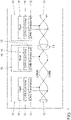
- FIG. 3 shows the new transmission frame format according to the CAN EL bus standard.
- the proposal is based on the message layout of the MAC frames as described in the ISO specification ISO 11898-1 from 2015 in chapter 10.4. The functionality and meaning of the individual fields are retained if deviations are not explicitly discussed here.
- control bit Detailed designation SOF Start of frame SRR Substitute remote request RTR Remote Transmission Request RRs Remote request substitution IDE identifier extension FDF Flexible Data Rate Format Indicator BRS bit rate switch IT I Error State Indicator EOF end of frame
- the representation is chosen in such a way that the individual bits per field of the transmission frame are each specified in one line.
- the Control Field, Data Field and CRC Field fields are transmitted at an increased data transmission rate.
- the increased data transfer rate is between 2000 Kbps and 12000 Kbps.
- the increment for setting the data transmission rate is 1000 Kbit/s.
- the low data transmission rate that is also used with the CAN FD bus still applies, i.e. the data transmission rate may be between 500 Kbit/s and 1500 Kbit/s lie.
- the increment for setting the data transmission rate here is 250 Kbit/s.
- the new transmission frame format is based on the FEFF format ("FD Extended Frame Format").
- the start field SF with the SOF bit remains unchanged.
- Extension0 bit and the Extension1 bit which are reserved for future extensions, are inserted into the arbitration field AF. These bits are not present in the FEFF format. Both bits Extension0 and Extension1 are transmitted with a "recessive" bus level.
- the identifier section in the arbitration field AF is extended to 32 bits.
- the 32 bits of the identifier section are transmitted in one piece and no longer in 2 different sections as with CAN FD. Accordingly, the bits SRR, RTR, RRS and IDE, which are otherwise provided for the purpose of controlling the transmission frame format, are also omitted.
- the section for specifying the length of the data field is extended to a length of 13 bits.
- the length of the user data field is specified in the number of bytes in bits DL0 to DL12.
- the numerical value in this section therefore specifies the exact number of bytes in the user data field.
- the maximum number of 8192 bytes can be encoded with 13 bits. However, any other whole number in the range can also be encoded with it.
- the length of the data field should be up to 4096 bytes so that a corresponding Ethernet packet can find space in it.
- the area of the control field with the length specification for the data field DF can specify more bytes with 13 bits, but is limited to 4096 bytes by a specification.
- control bits FDF, BRS and the reserved res bit between and control field CF and data field DF are omitted. Only the ESI bit remains in this position as a control bit.
- the data field DF itself can have a variable length. Depending on what is set, a maximum of 4096 bytes can follow here. This corresponds to a length of 32768 bits.
- the CRC field CF in which the CRC check code is entered, is extended to a CRC length of 32 bits.
- the check code is entered in the bit fields CRC0 to CRC31.
- the polynomial G(x) x32 + x26 + x23 + x22 + x16 + x12 + x11 + x10 + x8 + x7 + x5 + x4 + x2 + x + 1 is used to calculate the CRC check code.
- the selected polynomial corresponds to the polynomial used in the IEEE 802.3 specification for Ethernet.
- the CRC checksum is to be calculated from the SOF bit to the last bit of the stuff bit counter (stuff0).
- the Stuff Count section in the CRC field CF is changed to a length of 12 bits and affects bits Stuff0 to Stuff 11.
- the Stuff Count section the number of in the range from the SOF bit to the last bit of the data field DF inserted stuff bits.
- the number of stuff bits is encoded in binary.
- the use of bit stuffing is simplified compared to the bit stuffing used in the CAN FD standard.
- the CAN-EL bus has been optimized compared to the CAN-FD bus, as described in detail below.
- the insertion of stuff bits serves the purpose of synchronization with asynchronous data transmission.
- the signal edge of the start bit SOF of a CAN message which changes from recessive to dominant, is used to establish synchronization between the communication partners.
- a resynchronization mechanism ensures that synchronization is maintained.
- the resynchronization mechanism is based on the evaluation of the signal edges changing from recessive to dominant. So that the synchronization is maintained here, the bit stuffing mechanism was added to the CAN standard.
- the ISO standard ISO 11898-1 specifies that a complementary bit is to be transmitted after five homogeneous bits at the latest, even if a complementary bit would follow after five homogeneous bits anyway. The position of the stuff bits is known to the recipient due to the rule and he can ignore the stuff bits.
- bit stuffing algorithm for the new transmission format is modified in that a stuff bit is not inserted after 5 but only after 10 consecutive bits with the same bus level. As a result, fewer overhead bits are required in the data frame and the efficiency of the data transmission is increased as a result.
- variable bit stuffing is only to be carried out for the bits from the SOF to the last bit of the data field DF.
- Predefined stuff bits (FixedStuffx) are used starting with the CRC field CF.
- the FixedStuff bits are always inserted after 9 bits.
- the FixedStuff0 bit is transferred between the last data bit and the Stuff11 bit.
- the FixedStuff1 bit is transferred between the Stuff3 bit and the Stuff2 bit.
- the FixedStuff2 bit is transferred between the CRC26 bit and the CRC25 bit.
- the FixedStuff3 bit is transferred between the CRC17 bit and the CRC16 bit.
- the FixedStuff4 bit is transferred between the CRC8 bit and the CRC7 bit.
- the FixedStuff5 bit is transferred between the CRC0 bit and the CRCDel bit.
- the CRCDel bit which has the function of a CRC delimiter, remains unchanged and has the same function as in the CAN FD standard.
- the section with the EOF identifier is expanded to 11 bits.
- 11 recessive bits are transmitted instead of the 7 consecutive recessive bits that are usual with the CAN bus.
- the lengthening of the EOF symbol is due to the modification of the stuffing algorithm.
- the new stuffing rule is only violated after 11 consecutive bits of the same bus level. This is used here.
- the slower bit rate is called Slow Bit Rate.
- Bit Rate Fast The faster bit rate is called Bit Rate Fast.
- the Slow Bit Rate is set to range from 500 kbps to 1500 kbps. All bit rates are to be supported in 250 kbit/s increments.
- a range between 2000 kbps and 12000 kbps is set for the Fast Bit Rate. All bit rates in 1000 kbit/s steps should be supported in this area.
- FIG 5 shows the result of an exemplary calculation of the data transmission efficiency.
- the number of in the transmission frame transmitted user data bytes applied to the full packet length with 4096 bytes of user data.
- the resulting efficiency is plotted as a percentage along the ordinate.
- the stuff bits were not taken into account in the calculation.
- 500 kbit/s was set as the slow bit rate and 4 Mbit/s as the fast bit rate.
- 1000 Kbit/s was set as the slow bit rate and 10 Mbit/s as the fast bit rate.
- the determination of the identifiers for the CAN messages is not subject to any restrictions.
- the identifier is used to implement a prioritization concept.
- the identifier is used to decide which CAN node will prevail on the bus.
- the bus access method corresponds to the CSMA-CR method (Carrier Sense Multiple Access with Collision Resolution).
- the CSMA/CR procedure ensures that CAN nodes willing to transmit only access the CAN bus when it is free.
- the method of bit-by-bit bus arbitration on which the CSMA/CR procedure is based ensures that the CAN node with the highest-priority CAN message always prevails. In principle, the following applies: the higher the priority of a CAN message, the sooner it can be transmitted on the CAN bus. With an unfavorable system design, low-priority CAN messages even run the risk of not being transmitted at all. That is why the assignment of the IDs is very important for the realization of a deterministic data exchange.
- the 32 bits of the identifier are divided into two areas [message content] and [device].
- the [message content] area includes the high-order bits of the identifier.
- the [Device] area includes the low-order bits of the identifier.
- the size of the individual areas can be selected as required, but must be the same for all participants within a CAN network.
- 24 bits are reserved for the [message content] area and 8 bits for the [device] area. This makes it possible to make a fine differentiation with regard to the priority of messages in the network. If two participants want to send a message with the same priority at the same time, it is decided in the [Device] area which participant has priority.
- a lower binary number in the [message content] or [device] area actually corresponds to a higher priority.
- the dominant bus level always prevails on the CAN bus in the arbitration phase.
- a CAN node that recognizes that it has only sent the recessive bus level but recognizes that the dominant level is present gives up the arbitration.
- the individual bit positions of the arbitration field AF are numbered from 0 to 31 in the upper part of the illustration.
- the priority associated with the individual bit position is also specified for each bit.
- the bit position ID8 has the lowest priority Priority0 in the [message content] area and the bit position ID31 has the highest priority Priority23 in the [message content] area.
- the bit with the number ID0 in the [Device] area has the lowest priority and the bit with the number ID7 has the highest priority.
- the proposed method and associated devices can be implemented in various forms of hardware, software, firmware, special purpose processors or a combination thereof.
- Specialty processors can include Application Specific Integrated Circuits (ASICs), Reduced Instruction Set Computers (RISC), and/or Field Programmable Gate Arrays (FPGAs).
- ASICs Application Specific Integrated Circuits
- RISC Reduced Instruction Set Computers
- FPGAs Field Programmable Gate Arrays
- the proposed method and device is implemented as a combination of hardware and software.
- the software is preferably installed as an application program on a program storage device.
- it is a computer platform based machine that includes hardware such as one or more central processing units (CPU), random access memory (RAM), and one or more input/output (I/O) interfaces.
- An operating system is typically also installed on the computer platform.
- the various processes and functions described here can be part of the application program or a part that is executed via the operating system.
Claims (14)
- Procédé de transmission des données par l'intermédiaire d'un bus de communication série, dans lequel les données sont transmises avec une trame de transmission,la trame de transmission présentant au moins un champ d'arbitrage (AF) et un champ de données (DF), le champ d'arbitrage (AF) servant au réglage de l'accès au bus selon le procédé CSMA-CR, correspondant à Carrier Sense Multiple Access with Collision Resolution, par la priorisation des messages à l'aide d'un identificateur,un faible débit binaire étant réglé pour la phase d'arbitrage, et un débit binaire accru étant réglé pour la transmission des données dans le champ de données (DF), le champ de données (DF) présentant, dans une limite supérieure fixée qui est supérieure à 64 octets, une longueur variable pour un nombre arbitraire d'octets,caractérisé en ce queun champ de fin (EF) est en outre prévu dans la trame de transmission, et qu'au moins un code de fin de trame est inscrit dans le champ de fin (EF), le code de fin de trame présentant une longueur de 11 bits, afin de forcer une violation d'une nouvelle règle de bourrage de bits par l'envoi du code de fin de trame, de sorte que des participants qui n'étaient pas synchronisés correctement reconnaissent ce fait.
- Procédé selon la revendication 1, dans lequel la limite supérieure fixée concerne la valeur de 4096 octets.
- Procédé selon la revendication 1 ou 2, dans lequel la longueur du champ d'arbitrage (AF) est fixée à 32 bits.
- Procédé selon l'une quelconque des revendications précédentes, dans lequel un champ de commande (CF) est prévu dans la trame de transmission entre le champ d'arbitrage (AF) et le champ de données (DF), dans lequel au moins une section est prévue pour l'indication de la longueur par rapport au champ de données (DF).
- Procédé selon l'une quelconque des revendications précédentes, dans lequel un champ de CRC (CRCF) est prévu dans la trame de transmission, dans lequel au moins une section est prévue pour le code de contrôle CRC.
- Procédé selon la revendication 5, dans lequel un champ de début (SF) est prévu dans la trame de transmission et le code de contrôle CRC est calculé par le biais des champs champ de début (SF), champ d'arbitrage (AF), champ de commande (CF) et champ de données (DF).
- Procédé selon la revendication 6, dans lequel la transmission des données est effectuée de manière asynchrone et une resynchronisation est effectuée conformément à une règle de bourrage de bits afin de garantir un mode commun de la station de fin de données et de la station de réception de données, la règle de bourrage de bits étant appliquée pour les zones du champ de début (SF) jusqu'à la fin du champ de données (DF), la règle de bourrage de bits stipulant qu'un bit de bourrage n'est inséré qu'après un nombre défini de bits directement consécutifs ayant le même niveau de bus, le nombre défini étant un nombre naturel supérieur au nombre 5, le nombre des bits de bourrage insérés étant inscrit dans un section du champ de CRC (CRCF).
- Procédé selon l'une quelconque des revendications précédentes, dans lequel un bit de bourrage est inséré dans des positions prédéfinies de manière fixe dans le champ de CRC (CRCF).
- Procédé selon la revendication 8, dans lequel le champ de CRC (CRCF) commence par un bit de bourrage prédéfini de manière fixe et les autres bits de bourrage prédéfinis de manière fixe sont insérés des intervalles de 9 bits du champ de CRC (CRCF).
- Procédé selon l'une quelconque des revendications précédentes, dans lequel l'identifiant dans le champ d'arbitrage (AF) est divisé en sections d'identifiant de « contenu de message » et d'identifiant de « dispositifs ».
- Procédé selon la revendication 10, dans lequel la section contenant les bits de poids fort est réservée pour la priorisation du contenu de message et la section contenant les bits de poids faible est prévue pour l'identification de dispositifs.
- Procédé selon la revendication 11, dans lequel l'identifiant présente une longueur de 32 bits et la section contenant les bits de poids fort présente une longueur de 24 bits et la section contenant les bits de poids faible une longueur de 8 bits.
- Interface de bus conçue pour être utilisée dans le procédé selon l'une quelconque des revendications précédentes.
- Programme informatique, caractérisé en ce que le programme d'ordinateur est conçu pour exécuter, lors de son exécution dans une unité de calcul, les étapes côté émission et/ou les étapes côté réception du procédé de transmission de données selon l'une quelconque des revendications 1 à 12.
Applications Claiming Priority (2)
| Application Number | Priority Date | Filing Date | Title |
|---|---|---|---|
| DE102017211860.1A DE102017211860B3 (de) | 2017-07-11 | 2017-07-11 | Verfahren zur Übertragung von Daten über einen seriellen Kommunikationsbus, entsprechend ausgelegte Busschnittstelle sowie entsprechend ausgelegtes Computerprogramm |
| EP18176209.7A EP3429136B1 (fr) | 2017-07-11 | 2018-06-06 | Procede de transmission de donnees via un bus de communication serie, interface de bus correspondante et programme informatique correspondant |
Related Parent Applications (2)
| Application Number | Title | Priority Date | Filing Date |
|---|---|---|---|
| EP18176209.7A Division EP3429136B1 (fr) | 2017-07-11 | 2018-06-06 | Procede de transmission de donnees via un bus de communication serie, interface de bus correspondante et programme informatique correspondant |
| EP18176209.7A Division-Into EP3429136B1 (fr) | 2017-07-11 | 2018-06-06 | Procede de transmission de donnees via un bus de communication serie, interface de bus correspondante et programme informatique correspondant |
Publications (2)
| Publication Number | Publication Date |
|---|---|
| EP3661131A1 EP3661131A1 (fr) | 2020-06-03 |
| EP3661131B1 true EP3661131B1 (fr) | 2022-09-07 |
Family
ID=62684587
Family Applications (2)
| Application Number | Title | Priority Date | Filing Date |
|---|---|---|---|
| EP19218441.4A Active EP3661131B1 (fr) | 2017-07-11 | 2018-06-06 | Procédé de transmission des données par l'intermédiaire d'un bus de communication série, interface de bus conçue de manière correspondante ainsi que programme informatique conçu de manière correspondante |
| EP18176209.7A Active EP3429136B1 (fr) | 2017-07-11 | 2018-06-06 | Procede de transmission de donnees via un bus de communication serie, interface de bus correspondante et programme informatique correspondant |
Family Applications After (1)
| Application Number | Title | Priority Date | Filing Date |
|---|---|---|---|
| EP18176209.7A Active EP3429136B1 (fr) | 2017-07-11 | 2018-06-06 | Procede de transmission de donnees via un bus de communication serie, interface de bus correspondante et programme informatique correspondant |
Country Status (6)
| Country | Link |
|---|---|
| US (2) | US10530606B2 (fr) |
| EP (2) | EP3661131B1 (fr) |
| KR (1) | KR102023673B1 (fr) |
| CN (1) | CN109240970B (fr) |
| DE (1) | DE102017211860B3 (fr) |
| ES (1) | ES2929124T3 (fr) |
Families Citing this family (18)
| Publication number | Priority date | Publication date | Assignee | Title |
|---|---|---|---|---|
| DE102017211860B3 (de) * | 2017-07-11 | 2018-09-20 | Volkswagen Aktiengesellschaft | Verfahren zur Übertragung von Daten über einen seriellen Kommunikationsbus, entsprechend ausgelegte Busschnittstelle sowie entsprechend ausgelegtes Computerprogramm |
| CN110999226B (zh) | 2017-08-08 | 2022-05-10 | 大众汽车有限公司 | 用于经由串行通信总线来传输数据的方法、对应设计的总线接口和对应设计的计算机程序 |
| US10439840B1 (en) * | 2018-07-27 | 2019-10-08 | Nxp B.V. | Method and device for communicating data frames on a multi-master bus |
| DE102018218721A1 (de) | 2018-10-31 | 2020-04-30 | Robert Bosch Gmbh | Teilnehmerstation für ein serielles Bussystem und Verfahren zum Senden einer Nachricht in einem seriellen Bussystem |
| DE102018221681A1 (de) * | 2018-12-13 | 2020-06-18 | Robert Bosch Gmbh | Teilnehmerstation für ein serielles Bussystem und Verfahren zur Kommunikation in einem seriellen Bussystem |
| DE102019201316A1 (de) * | 2019-02-01 | 2020-08-06 | Robert Bosch Gmbh | Teilnehmerstation für ein serielles Bussystem und Verfahren zur Kommunikation in einem seriellen Bussystem |
| KR102006634B1 (ko) * | 2019-03-06 | 2019-08-02 | 브이에스아이 주식회사 | 이종의 통신방식들 중 하나로 적응시킴으로써 이종 통신방식의 노드들이 단일 버스를 공유할 수 있게 하는 방법과 그 방법을 위한 기기 |
| JP7114515B2 (ja) | 2019-03-14 | 2022-08-08 | 国立大学法人東海国立大学機構 | 通信装置、通信システム及びメッセージ調停方法 |
| DE102019204115A1 (de) * | 2019-03-26 | 2020-10-01 | Robert Bosch Gmbh | Teilnehmerstation für ein serielles Bussystem und Verfahren zur Kommunikation in einem seriellen Bussystem |
| DE102019213783A1 (de) * | 2019-09-11 | 2021-03-11 | Robert Bosch Gmbh | Teilnehmerstation für ein serielles Bussystem und Verfahren zur Kommunikation in einem seriellen Bussystem |
| DE102019218715A1 (de) * | 2019-12-02 | 2021-06-02 | Robert Bosch Gmbh | Teilnehmerstation für ein serielles Bussystem und Verfahren zur Kommunikation in einem seriellen Bussystem |
| CN111130695B (zh) * | 2019-12-10 | 2022-09-20 | 卡斯柯信号有限公司 | 通过冗余码字计算canopen协议crc的方法 |
| KR20210073976A (ko) * | 2019-12-11 | 2021-06-21 | 현대자동차주식회사 | 차량용 게이트웨이 및 차량용 게이트웨이의 제어방법 |
| US20210255984A1 (en) * | 2020-02-19 | 2021-08-19 | Magna Electronics Inc. | Vehicular sensor testing system with standardized i2c communication |
| GB2592967A (en) * | 2020-03-12 | 2021-09-15 | Warwick Control Tech Ltd | A method for monitoring a network |
| CN112732511B (zh) * | 2021-01-14 | 2022-10-25 | 上海镭隆科技发展有限公司 | 一种基于hdlc协议高性能高速同步422仿真器板卡 |
| CN112765072A (zh) * | 2021-01-28 | 2021-05-07 | 北京方天长久科技股份有限公司 | 一种串行互联总线数据帧格式及传输方法 |
| DE102021206175A1 (de) * | 2021-06-17 | 2022-12-22 | Robert Bosch Gesellschaft mit beschränkter Haftung | Ansteuerungssystem, Steuermodul und Verfahren zum Betreiben |
Family Cites Families (16)
| Publication number | Priority date | Publication date | Assignee | Title |
|---|---|---|---|---|
| JP3042549B2 (ja) * | 1991-08-23 | 2000-05-15 | 古河電気工業株式会社 | 多重伝送方式の受信応答方法 |
| FI88841C (fi) * | 1991-10-30 | 1993-07-12 | Nokia Telecommunications Oy | Foerfarande foer att behandla dataoeverfoeringsramar av vaexlande laengd med en kanalstyrenhet och foer att placera desamma till ett cykliskt buffertminne |
| DE102011006884A1 (de) | 2011-04-06 | 2012-10-11 | Robert Bosch Gmbh | Verfahren und Vorrichtung zur Erhöhung der Datenübertragungskapazität in einem seriellen Bussystem |
| WO2012136546A1 (fr) * | 2011-04-06 | 2012-10-11 | Robert Bosch Gmbh | Procédé et dispositif d'adaptation de la sécurité de transmission de données dans un système de bus sériel |
| JP5770924B2 (ja) * | 2011-04-06 | 2015-08-26 | ローベルト ボッシュ ゲゼルシャフト ミット ベシュレンクテル ハフツング | 直列バスシステム内でデータ伝送容量を上げるための方法及び装置 |
| EP2521319B1 (fr) * | 2011-05-02 | 2015-10-14 | Robert Bosch GmbH | Réseau de type CAN avec taux de débit de données flexible |
| DE102011122843A1 (de) | 2011-06-29 | 2013-01-31 | Robert Bosch Gmbh | Verfahren und Vorrichtung zur seriellen Datenübertragung mit flexibler Nachrichtengröße und variabler Bitlänge |
| DE102012224024A1 (de) | 2012-12-20 | 2014-06-26 | Robert Bosch Gmbh | Datenübertragung unter Nutzung eines Protokollausnahmezustands |
| US9419737B2 (en) * | 2013-03-15 | 2016-08-16 | Concio Holdings LLC | High speed embedded protocol for distributed control systems |
| DE102014205120A1 (de) * | 2014-03-19 | 2015-09-24 | Robert Bosch Gmbh | Teilnehmerstation für ein Bussystem und Verfahren zur Erhöhung der Übertragungskapazität in einem Bussystem |
| CN110406485B (zh) * | 2014-04-17 | 2023-01-06 | 松下电器(美国)知识产权公司 | 非法检测方法及车载网络系统 |
| CN106464559B (zh) * | 2014-05-26 | 2023-05-23 | 康西欧控股有限公司 | 用于分布式控制系统的高速嵌入式协议 |
| US10673565B2 (en) * | 2014-09-30 | 2020-06-02 | Concio Holdings LLC | Confirming data accuracy in a distributed control system |
| DE102015204714A1 (de) | 2015-03-16 | 2016-09-22 | Robert Bosch Gmbh | Teilnehmerstation für ein Bussystem und Verfahren zur Datenübertragung in einem Bussystem |
| US10050983B2 (en) * | 2015-11-13 | 2018-08-14 | Kabushiki Kaisha Toshiba | Communication system, receiving apparatus, receiving method, and computer program product |
| DE102017211860B3 (de) * | 2017-07-11 | 2018-09-20 | Volkswagen Aktiengesellschaft | Verfahren zur Übertragung von Daten über einen seriellen Kommunikationsbus, entsprechend ausgelegte Busschnittstelle sowie entsprechend ausgelegtes Computerprogramm |
-
2017
- 2017-07-11 DE DE102017211860.1A patent/DE102017211860B3/de not_active Expired - Fee Related
-
2018
- 2018-06-06 ES ES19218441T patent/ES2929124T3/es active Active
- 2018-06-06 EP EP19218441.4A patent/EP3661131B1/fr active Active
- 2018-06-06 EP EP18176209.7A patent/EP3429136B1/fr active Active
- 2018-07-06 US US16/029,054 patent/US10530606B2/en active Active
- 2018-07-09 KR KR1020180079333A patent/KR102023673B1/ko active IP Right Grant
- 2018-07-10 CN CN201810750576.8A patent/CN109240970B/zh active Active
-
2020
- 2020-01-03 US US16/733,902 patent/US11146420B2/en active Active
Also Published As
| Publication number | Publication date |
|---|---|
| CN109240970B (zh) | 2022-06-03 |
| DE102017211860B3 (de) | 2018-09-20 |
| US10530606B2 (en) | 2020-01-07 |
| KR20190006922A (ko) | 2019-01-21 |
| US11146420B2 (en) | 2021-10-12 |
| KR102023673B1 (ko) | 2019-09-23 |
| US20190020499A1 (en) | 2019-01-17 |
| ES2929124T3 (es) | 2022-11-25 |
| EP3429136A1 (fr) | 2019-01-16 |
| EP3429136B1 (fr) | 2020-03-25 |
| CN109240970A (zh) | 2019-01-18 |
| US20200145254A1 (en) | 2020-05-07 |
| EP3661131A1 (fr) | 2020-06-03 |
Similar Documents
| Publication | Publication Date | Title |
|---|---|---|
| EP3661131B1 (fr) | Procédé de transmission des données par l'intermédiaire d'un bus de communication série, interface de bus conçue de manière correspondante ainsi que programme informatique conçu de manière correspondante | |
| EP3665875B1 (fr) | Procédé de transmission de données via un bus de communication série, interface de bus conçue de manière correspondante ainsi que programme d'ordinateur conçu de manière correspondante | |
| DE102018105007B4 (de) | Verfahren zur Übertragung von Daten über einen Kommunikationskanal, entsprechend ausgelegte Vorrichtung und Kommunikationsschnittstelle sowie entsprechend ausgelegtes Computerprogramm | |
| EP2702495B1 (fr) | Procédé et dispositif de transmission de données sérielle adaptée à la capacité mémoire | |
| EP2695074B1 (fr) | Procédé et dispositif d'adaptation de la sécurité de transmission de données dans un système de bus sériel | |
| EP2695076B1 (fr) | Procédé et dispositif d'augmentation de la capacité de transmission de données dans un système de bus sériel | |
| EP3248362B1 (fr) | Transmission de données dans un réseau de communication | |
| EP1943570A1 (fr) | Procede et systeme de transmission de donnees cycliques et acycliques | |
| WO2020187985A1 (fr) | Procédé de surveillance de la communication sur un bus de communication, dispositif électronique de branchement à un bus de communication ainsi que véhicule | |
| WO2018077528A1 (fr) | Détection de manipulations dans un réseau can par vérification d'identifiants can | |
| DE102017012214B4 (de) | Verfahren zur Übertragung von Daten über einen seriellen Kommunikationsbus, entsprechend ausgelegte Busschnittstelle sowie entsprechend ausgelegtes Computerprogramm | |
| WO2019057882A1 (fr) | Procédé de surveillance de la communication sur un bus de communication ainsi que dispositif électronique destiné à la connexion à un bus de communication | |
| EP3152872B1 (fr) | Unité de transmission avec fonction de vérification | |
| DE102019213322A1 (de) | Ethernet Physical Layer Transceiver für Zweidraht-Bustopologie | |
| EP3725041A1 (fr) | Procédé de fourniture d'informations pour la localisation d'erreurs dans un réseau de communication d'un appareil, station participante à un bus conçue de manière correspondante et véhicule | |
| DE102011006884A1 (de) | Verfahren und Vorrichtung zur Erhöhung der Datenübertragungskapazität in einem seriellen Bussystem | |
| WO2021099186A2 (fr) | Procédé de surveillance de la communication sur un bus de communication, dispositif électronique pour connexion à un bus de communication ainsi que dispositif de surveillance central pour connexion à un bus de communication | |
| WO2012136783A1 (fr) | Procédé et dispositif destinés à la transmission de données entre des systèmes de bus reliés | |
| DE102012201669B4 (de) | Verfahren und Kommunikationscontroller zur Datenübertragung zwischen zwei mittels Übertragungsstrecken verbundenen Datenverarbeitungseinheiten | |
| DE102021201120A1 (de) | Teilnehmerstation für ein serielles Bussystem und Verfahren zur Kommunikation in einem seriellen Bussystem | |
| DE102011122801A1 (de) | Verfahren und Vorrichtung zur Anpassung der Datenübertragungssicherheit in einem seriellen Bussystem | |
| DE102011006875A1 (de) | Verfahren und Vorrichtung zur Anpassung der Datenübertragungssicherheit in einem seriellen Bussystem | |
| WO2020083960A1 (fr) | Station d'abonné pour un système de bus série et procédé de transmission de données avec protection contre les manipulations dans un système de bus série | |
| DE102011017539A1 (de) | Verfahren und Vorrichtung zur an Speichergrößen angepassten seriellen Datenübertragung | |
| DE102011122826A1 (de) | Verfahren und Vorrichtung zur an Speichergrößen angepassten seriellen Datenübertragung |
Legal Events
| Date | Code | Title | Description |
|---|---|---|---|
| PUAI | Public reference made under article 153(3) epc to a published international application that has entered the european phase |
Free format text: ORIGINAL CODE: 0009012 |
|
| STAA | Information on the status of an ep patent application or granted ep patent |
Free format text: STATUS: THE APPLICATION HAS BEEN PUBLISHED |
|
| AC | Divisional application: reference to earlier application |
Ref document number: 3429136 Country of ref document: EP Kind code of ref document: P |
|
| AK | Designated contracting states |
Kind code of ref document: A1 Designated state(s): AL AT BE BG CH CY CZ DE DK EE ES FI FR GB GR HR HU IE IS IT LI LT LU LV MC MK MT NL NO PL PT RO RS SE SI SK SM TR |
|
| STAA | Information on the status of an ep patent application or granted ep patent |
Free format text: STATUS: REQUEST FOR EXAMINATION WAS MADE |
|
| 17P | Request for examination filed |
Effective date: 20201203 |
|
| RBV | Designated contracting states (corrected) |
Designated state(s): AL AT BE BG CH CY CZ DE DK EE ES FI FR GB GR HR HU IE IS IT LI LT LU LV MC MK MT NL NO PL PT RO RS SE SI SK SM TR |
|
| RIC1 | Information provided on ipc code assigned before grant |
Ipc: G06F 13/42 20060101ALI20220201BHEP Ipc: G06F 13/376 20060101ALI20220201BHEP Ipc: H04L 12/40 20060101ALI20220201BHEP Ipc: H04L 12/413 20060101AFI20220201BHEP |
|
| GRAP | Despatch of communication of intention to grant a patent |
Free format text: ORIGINAL CODE: EPIDOSNIGR1 |
|
| STAA | Information on the status of an ep patent application or granted ep patent |
Free format text: STATUS: GRANT OF PATENT IS INTENDED |
|
| INTG | Intention to grant announced |
Effective date: 20220318 |
|
| RAP3 | Party data changed (applicant data changed or rights of an application transferred) |
Owner name: VOLKSWAGEN AKTIENGESELLSCHAFT |
|
| GRAS | Grant fee paid |
Free format text: ORIGINAL CODE: EPIDOSNIGR3 |
|
| GRAA | (expected) grant |
Free format text: ORIGINAL CODE: 0009210 |
|
| STAA | Information on the status of an ep patent application or granted ep patent |
Free format text: STATUS: THE PATENT HAS BEEN GRANTED |
|
| AC | Divisional application: reference to earlier application |
Ref document number: 3429136 Country of ref document: EP Kind code of ref document: P |
|
| AK | Designated contracting states |
Kind code of ref document: B1 Designated state(s): AL AT BE BG CH CY CZ DE DK EE ES FI FR GB GR HR HU IE IS IT LI LT LU LV MC MK MT NL NO PL PT RO RS SE SI SK SM TR |
|
| REG | Reference to a national code |
Ref country code: GB Ref legal event code: FG4D Free format text: NOT ENGLISH |
|
| REG | Reference to a national code |
Ref country code: CH Ref legal event code: EP Ref country code: AT Ref legal event code: REF Ref document number: 1517980 Country of ref document: AT Kind code of ref document: T Effective date: 20220915 |
|
| REG | Reference to a national code |
Ref country code: IE Ref legal event code: FG4D Free format text: LANGUAGE OF EP DOCUMENT: GERMAN |
|
| REG | Reference to a national code |
Ref country code: DE Ref legal event code: R096 Ref document number: 502018010610 Country of ref document: DE |
|
| REG | Reference to a national code |
Ref country code: ES Ref legal event code: FG2A Ref document number: 2929124 Country of ref document: ES Kind code of ref document: T3 Effective date: 20221125 |
|
| REG | Reference to a national code |
Ref country code: LT Ref legal event code: MG9D |
|
| REG | Reference to a national code |
Ref country code: NL Ref legal event code: MP Effective date: 20220907 |
|
| PG25 | Lapsed in a contracting state [announced via postgrant information from national office to epo] |
Ref country code: SE Free format text: LAPSE BECAUSE OF FAILURE TO SUBMIT A TRANSLATION OF THE DESCRIPTION OR TO PAY THE FEE WITHIN THE PRESCRIBED TIME-LIMIT Effective date: 20220907 Ref country code: RS Free format text: LAPSE BECAUSE OF FAILURE TO SUBMIT A TRANSLATION OF THE DESCRIPTION OR TO PAY THE FEE WITHIN THE PRESCRIBED TIME-LIMIT Effective date: 20220907 Ref country code: NO Free format text: LAPSE BECAUSE OF FAILURE TO SUBMIT A TRANSLATION OF THE DESCRIPTION OR TO PAY THE FEE WITHIN THE PRESCRIBED TIME-LIMIT Effective date: 20221207 Ref country code: LV Free format text: LAPSE BECAUSE OF FAILURE TO SUBMIT A TRANSLATION OF THE DESCRIPTION OR TO PAY THE FEE WITHIN THE PRESCRIBED TIME-LIMIT Effective date: 20220907 Ref country code: LT Free format text: LAPSE BECAUSE OF FAILURE TO SUBMIT A TRANSLATION OF THE DESCRIPTION OR TO PAY THE FEE WITHIN THE PRESCRIBED TIME-LIMIT Effective date: 20220907 Ref country code: FI Free format text: LAPSE BECAUSE OF FAILURE TO SUBMIT A TRANSLATION OF THE DESCRIPTION OR TO PAY THE FEE WITHIN THE PRESCRIBED TIME-LIMIT Effective date: 20220907 |
|
| PG25 | Lapsed in a contracting state [announced via postgrant information from national office to epo] |
Ref country code: HR Free format text: LAPSE BECAUSE OF FAILURE TO SUBMIT A TRANSLATION OF THE DESCRIPTION OR TO PAY THE FEE WITHIN THE PRESCRIBED TIME-LIMIT Effective date: 20220907 Ref country code: GR Free format text: LAPSE BECAUSE OF FAILURE TO SUBMIT A TRANSLATION OF THE DESCRIPTION OR TO PAY THE FEE WITHIN THE PRESCRIBED TIME-LIMIT Effective date: 20221208 |
|
| PG25 | Lapsed in a contracting state [announced via postgrant information from national office to epo] |
Ref country code: SM Free format text: LAPSE BECAUSE OF FAILURE TO SUBMIT A TRANSLATION OF THE DESCRIPTION OR TO PAY THE FEE WITHIN THE PRESCRIBED TIME-LIMIT Effective date: 20220907 Ref country code: RO Free format text: LAPSE BECAUSE OF FAILURE TO SUBMIT A TRANSLATION OF THE DESCRIPTION OR TO PAY THE FEE WITHIN THE PRESCRIBED TIME-LIMIT Effective date: 20220907 Ref country code: PT Free format text: LAPSE BECAUSE OF FAILURE TO SUBMIT A TRANSLATION OF THE DESCRIPTION OR TO PAY THE FEE WITHIN THE PRESCRIBED TIME-LIMIT Effective date: 20230109 |
|
| PG25 | Lapsed in a contracting state [announced via postgrant information from national office to epo] |
Ref country code: SK Free format text: LAPSE BECAUSE OF FAILURE TO SUBMIT A TRANSLATION OF THE DESCRIPTION OR TO PAY THE FEE WITHIN THE PRESCRIBED TIME-LIMIT Effective date: 20220907 Ref country code: PL Free format text: LAPSE BECAUSE OF FAILURE TO SUBMIT A TRANSLATION OF THE DESCRIPTION OR TO PAY THE FEE WITHIN THE PRESCRIBED TIME-LIMIT Effective date: 20220907 Ref country code: IS Free format text: LAPSE BECAUSE OF FAILURE TO SUBMIT A TRANSLATION OF THE DESCRIPTION OR TO PAY THE FEE WITHIN THE PRESCRIBED TIME-LIMIT Effective date: 20230107 Ref country code: EE Free format text: LAPSE BECAUSE OF FAILURE TO SUBMIT A TRANSLATION OF THE DESCRIPTION OR TO PAY THE FEE WITHIN THE PRESCRIBED TIME-LIMIT Effective date: 20220907 |
|
| REG | Reference to a national code |
Ref country code: DE Ref legal event code: R097 Ref document number: 502018010610 Country of ref document: DE |
|
| P01 | Opt-out of the competence of the unified patent court (upc) registered |
Effective date: 20230523 |
|
| PG25 | Lapsed in a contracting state [announced via postgrant information from national office to epo] |
Ref country code: NL Free format text: LAPSE BECAUSE OF FAILURE TO SUBMIT A TRANSLATION OF THE DESCRIPTION OR TO PAY THE FEE WITHIN THE PRESCRIBED TIME-LIMIT Effective date: 20220907 Ref country code: AL Free format text: LAPSE BECAUSE OF FAILURE TO SUBMIT A TRANSLATION OF THE DESCRIPTION OR TO PAY THE FEE WITHIN THE PRESCRIBED TIME-LIMIT Effective date: 20220907 |
|
| PLBE | No opposition filed within time limit |
Free format text: ORIGINAL CODE: 0009261 |
|
| STAA | Information on the status of an ep patent application or granted ep patent |
Free format text: STATUS: NO OPPOSITION FILED WITHIN TIME LIMIT |
|
| PG25 | Lapsed in a contracting state [announced via postgrant information from national office to epo] |
Ref country code: DK Free format text: LAPSE BECAUSE OF FAILURE TO SUBMIT A TRANSLATION OF THE DESCRIPTION OR TO PAY THE FEE WITHIN THE PRESCRIBED TIME-LIMIT Effective date: 20220907 |
|
| PGFP | Annual fee paid to national office [announced via postgrant information from national office to epo] |
Ref country code: FR Payment date: 20230622 Year of fee payment: 6 Ref country code: DE Payment date: 20230630 Year of fee payment: 6 Ref country code: CZ Payment date: 20230605 Year of fee payment: 6 |
|
| 26N | No opposition filed |
Effective date: 20230608 |
|
| PG25 | Lapsed in a contracting state [announced via postgrant information from national office to epo] |
Ref country code: SI Free format text: LAPSE BECAUSE OF FAILURE TO SUBMIT A TRANSLATION OF THE DESCRIPTION OR TO PAY THE FEE WITHIN THE PRESCRIBED TIME-LIMIT Effective date: 20220907 |
|
| PGFP | Annual fee paid to national office [announced via postgrant information from national office to epo] |
Ref country code: IT Payment date: 20230620 Year of fee payment: 6 Ref country code: GB Payment date: 20230620 Year of fee payment: 6 Ref country code: ES Payment date: 20230721 Year of fee payment: 6 |
|
| PG25 | Lapsed in a contracting state [announced via postgrant information from national office to epo] |
Ref country code: MC Free format text: LAPSE BECAUSE OF FAILURE TO SUBMIT A TRANSLATION OF THE DESCRIPTION OR TO PAY THE FEE WITHIN THE PRESCRIBED TIME-LIMIT Effective date: 20220907 |
|
| PG25 | Lapsed in a contracting state [announced via postgrant information from national office to epo] |
Ref country code: MC Free format text: LAPSE BECAUSE OF FAILURE TO SUBMIT A TRANSLATION OF THE DESCRIPTION OR TO PAY THE FEE WITHIN THE PRESCRIBED TIME-LIMIT Effective date: 20220907 |
|
| REG | Reference to a national code |
Ref country code: CH Ref legal event code: PL |
|
| REG | Reference to a national code |
Ref country code: BE Ref legal event code: MM Effective date: 20230630 |
|
| PG25 | Lapsed in a contracting state [announced via postgrant information from national office to epo] |
Ref country code: LU Free format text: LAPSE BECAUSE OF NON-PAYMENT OF DUE FEES Effective date: 20230606 |
|
| REG | Reference to a national code |
Ref country code: IE Ref legal event code: MM4A |
|
| PG25 | Lapsed in a contracting state [announced via postgrant information from national office to epo] |
Ref country code: LU Free format text: LAPSE BECAUSE OF NON-PAYMENT OF DUE FEES Effective date: 20230606 |
|
| PG25 | Lapsed in a contracting state [announced via postgrant information from national office to epo] |
Ref country code: IE Free format text: LAPSE BECAUSE OF NON-PAYMENT OF DUE FEES Effective date: 20230606 |
|
| PG25 | Lapsed in a contracting state [announced via postgrant information from national office to epo] |
Ref country code: IE Free format text: LAPSE BECAUSE OF NON-PAYMENT OF DUE FEES Effective date: 20230606 Ref country code: CH Free format text: LAPSE BECAUSE OF NON-PAYMENT OF DUE FEES Effective date: 20230630 |