EP3661131B1 - Method for transmitting data via a serial communication bus, bus interface designed for this purpose, and correspondingly designed computer program - Google Patents
Method for transmitting data via a serial communication bus, bus interface designed for this purpose, and correspondingly designed computer program Download PDFInfo
- Publication number
- EP3661131B1 EP3661131B1 EP19218441.4A EP19218441A EP3661131B1 EP 3661131 B1 EP3661131 B1 EP 3661131B1 EP 19218441 A EP19218441 A EP 19218441A EP 3661131 B1 EP3661131 B1 EP 3661131B1
- Authority
- EP
- European Patent Office
- Prior art keywords
- field
- data
- bus
- bits
- bit
- Prior art date
- Legal status (The legal status is an assumption and is not a legal conclusion. Google has not performed a legal analysis and makes no representation as to the accuracy of the status listed.)
- Active
Links
- 238000000034 method Methods 0.000 title claims description 40
- 238000004891 communication Methods 0.000 title claims description 26
- 238000004590 computer program Methods 0.000 title claims description 6
- 230000005540 biological transmission Effects 0.000 claims description 80
- 230000001360 synchronised effect Effects 0.000 claims description 5
- 238000012795 verification Methods 0.000 claims 2
- 238000005516 engineering process Methods 0.000 description 10
- 230000008569 process Effects 0.000 description 7
- 230000008901 benefit Effects 0.000 description 6
- 238000004364 calculation method Methods 0.000 description 6
- 230000006870 function Effects 0.000 description 6
- 238000004422 calculation algorithm Methods 0.000 description 4
- 238000011161 development Methods 0.000 description 4
- 230000018109 developmental process Effects 0.000 description 4
- 230000006855 networking Effects 0.000 description 4
- 238000004378 air conditioning Methods 0.000 description 3
- 230000000295 complement effect Effects 0.000 description 3
- 230000007246 mechanism Effects 0.000 description 3
- 230000000717 retained effect Effects 0.000 description 3
- 230000011218 segmentation Effects 0.000 description 3
- 101100172132 Mus musculus Eif3a gene Proteins 0.000 description 2
- 230000006978 adaptation Effects 0.000 description 2
- 238000013459 approach Methods 0.000 description 2
- 230000008859 change Effects 0.000 description 2
- 238000006243 chemical reaction Methods 0.000 description 2
- 238000013461 design Methods 0.000 description 2
- 238000010586 diagram Methods 0.000 description 2
- 238000003780 insertion Methods 0.000 description 2
- 230000037431 insertion Effects 0.000 description 2
- 238000012986 modification Methods 0.000 description 2
- 230000004048 modification Effects 0.000 description 2
- 238000012544 monitoring process Methods 0.000 description 2
- 238000012545 processing Methods 0.000 description 2
- 230000008054 signal transmission Effects 0.000 description 2
- 238000012546 transfer Methods 0.000 description 2
- 101100494437 Glycine max IFS2 gene Proteins 0.000 description 1
- 101100494439 Glycyrrhiza uralensis CYP93C2 gene Proteins 0.000 description 1
- 101100140586 Saccharomyces cerevisiae (strain ATCC 204508 / S288c) NAM7 gene Proteins 0.000 description 1
- 230000001133 acceleration Effects 0.000 description 1
- 238000003491 array Methods 0.000 description 1
- 230000009286 beneficial effect Effects 0.000 description 1
- 230000015572 biosynthetic process Effects 0.000 description 1
- 125000004122 cyclic group Chemical group 0.000 description 1
- 230000007423 decrease Effects 0.000 description 1
- 230000001419 dependent effect Effects 0.000 description 1
- 238000003745 diagnosis Methods 0.000 description 1
- 230000004069 differentiation Effects 0.000 description 1
- 230000000694 effects Effects 0.000 description 1
- 238000011156 evaluation Methods 0.000 description 1
- 238000007689 inspection Methods 0.000 description 1
- 239000013307 optical fiber Substances 0.000 description 1
- 230000008092 positive effect Effects 0.000 description 1
- 238000002360 preparation method Methods 0.000 description 1
- 238000012913 prioritisation Methods 0.000 description 1
- 230000035484 reaction time Effects 0.000 description 1
- 238000011084 recovery Methods 0.000 description 1
- 238000005070 sampling Methods 0.000 description 1
- 230000011664 signaling Effects 0.000 description 1
- 238000006467 substitution reaction Methods 0.000 description 1
Images


Classifications
-
- G—PHYSICS
- G06—COMPUTING; CALCULATING OR COUNTING
- G06F—ELECTRIC DIGITAL DATA PROCESSING
- G06F13/00—Interconnection of, or transfer of information or other signals between, memories, input/output devices or central processing units
- G06F13/38—Information transfer, e.g. on bus
- G06F13/42—Bus transfer protocol, e.g. handshake; Synchronisation
- G06F13/4282—Bus transfer protocol, e.g. handshake; Synchronisation on a serial bus, e.g. I2C bus, SPI bus
-
- H—ELECTRICITY
- H04—ELECTRIC COMMUNICATION TECHNIQUE
- H04L—TRANSMISSION OF DIGITAL INFORMATION, e.g. TELEGRAPHIC COMMUNICATION
- H04L12/00—Data switching networks
- H04L12/28—Data switching networks characterised by path configuration, e.g. LAN [Local Area Networks] or WAN [Wide Area Networks]
- H04L12/40—Bus networks
- H04L12/407—Bus networks with decentralised control
- H04L12/413—Bus networks with decentralised control with random access, e.g. carrier-sense multiple-access with collision detection [CSMA-CD]
- H04L12/4135—Bus networks with decentralised control with random access, e.g. carrier-sense multiple-access with collision detection [CSMA-CD] using bit-wise arbitration
-
- H—ELECTRICITY
- H04—ELECTRIC COMMUNICATION TECHNIQUE
- H04L—TRANSMISSION OF DIGITAL INFORMATION, e.g. TELEGRAPHIC COMMUNICATION
- H04L12/00—Data switching networks
- H04L12/28—Data switching networks characterised by path configuration, e.g. LAN [Local Area Networks] or WAN [Wide Area Networks]
- H04L12/40—Bus networks
- H04L12/40006—Architecture of a communication node
- H04L12/40032—Details regarding a bus interface enhancer
-
- G—PHYSICS
- G06—COMPUTING; CALCULATING OR COUNTING
- G06F—ELECTRIC DIGITAL DATA PROCESSING
- G06F13/00—Interconnection of, or transfer of information or other signals between, memories, input/output devices or central processing units
- G06F13/14—Handling requests for interconnection or transfer
- G06F13/36—Handling requests for interconnection or transfer for access to common bus or bus system
- G06F13/368—Handling requests for interconnection or transfer for access to common bus or bus system with decentralised access control
- G06F13/376—Handling requests for interconnection or transfer for access to common bus or bus system with decentralised access control using a contention resolving method, e.g. collision detection, collision avoidance
-
- H—ELECTRICITY
- H03—ELECTRONIC CIRCUITRY
- H03M—CODING; DECODING; CODE CONVERSION IN GENERAL
- H03M13/00—Coding, decoding or code conversion, for error detection or error correction; Coding theory basic assumptions; Coding bounds; Error probability evaluation methods; Channel models; Simulation or testing of codes
- H03M13/03—Error detection or forward error correction by redundancy in data representation, i.e. code words containing more digits than the source words
- H03M13/05—Error detection or forward error correction by redundancy in data representation, i.e. code words containing more digits than the source words using block codes, i.e. a predetermined number of check bits joined to a predetermined number of information bits
- H03M13/09—Error detection only, e.g. using cyclic redundancy check [CRC] codes or single parity bit
-
- H—ELECTRICITY
- H04—ELECTRIC COMMUNICATION TECHNIQUE
- H04L—TRANSMISSION OF DIGITAL INFORMATION, e.g. TELEGRAPHIC COMMUNICATION
- H04L1/00—Arrangements for detecting or preventing errors in the information received
- H04L1/004—Arrangements for detecting or preventing errors in the information received by using forward error control
-
- H—ELECTRICITY
- H04—ELECTRIC COMMUNICATION TECHNIQUE
- H04L—TRANSMISSION OF DIGITAL INFORMATION, e.g. TELEGRAPHIC COMMUNICATION
- H04L12/00—Data switching networks
- H04L12/28—Data switching networks characterised by path configuration, e.g. LAN [Local Area Networks] or WAN [Wide Area Networks]
- H04L12/40—Bus networks
- H04L12/40052—High-speed IEEE 1394 serial bus
- H04L12/40084—Bus arbitration
-
- H—ELECTRICITY
- H04—ELECTRIC COMMUNICATION TECHNIQUE
- H04L—TRANSMISSION OF DIGITAL INFORMATION, e.g. TELEGRAPHIC COMMUNICATION
- H04L12/00—Data switching networks
- H04L12/28—Data switching networks characterised by path configuration, e.g. LAN [Local Area Networks] or WAN [Wide Area Networks]
- H04L12/40—Bus networks
- H04L12/4013—Management of data rate on the bus
-
- H—ELECTRICITY
- H04—ELECTRIC COMMUNICATION TECHNIQUE
- H04L—TRANSMISSION OF DIGITAL INFORMATION, e.g. TELEGRAPHIC COMMUNICATION
- H04L12/00—Data switching networks
- H04L12/28—Data switching networks characterised by path configuration, e.g. LAN [Local Area Networks] or WAN [Wide Area Networks]
- H04L12/40—Bus networks
- H04L12/40143—Bus networks involving priority mechanisms
- H04L12/40156—Bus networks involving priority mechanisms by using dedicated slots associated with a priority level
-
- H—ELECTRICITY
- H04—ELECTRIC COMMUNICATION TECHNIQUE
- H04L—TRANSMISSION OF DIGITAL INFORMATION, e.g. TELEGRAPHIC COMMUNICATION
- H04L12/00—Data switching networks
- H04L12/28—Data switching networks characterised by path configuration, e.g. LAN [Local Area Networks] or WAN [Wide Area Networks]
- H04L12/40—Bus networks
- H04L12/40143—Bus networks involving priority mechanisms
- H04L12/40163—Bus networks involving priority mechanisms by assigning priority to messages according to a message field
-
- H—ELECTRICITY
- H04—ELECTRIC COMMUNICATION TECHNIQUE
- H04L—TRANSMISSION OF DIGITAL INFORMATION, e.g. TELEGRAPHIC COMMUNICATION
- H04L12/00—Data switching networks
- H04L12/28—Data switching networks characterised by path configuration, e.g. LAN [Local Area Networks] or WAN [Wide Area Networks]
- H04L12/40—Bus networks
- H04L2012/40208—Bus networks characterized by the use of a particular bus standard
- H04L2012/40215—Controller Area Network CAN
-
- H—ELECTRICITY
- H04—ELECTRIC COMMUNICATION TECHNIQUE
- H04L—TRANSMISSION OF DIGITAL INFORMATION, e.g. TELEGRAPHIC COMMUNICATION
- H04L12/00—Data switching networks
- H04L12/28—Data switching networks characterised by path configuration, e.g. LAN [Local Area Networks] or WAN [Wide Area Networks]
- H04L12/40—Bus networks
- H04L2012/40267—Bus for use in transportation systems
- H04L2012/40273—Bus for use in transportation systems the transportation system being a vehicle
Definitions
- the invention relates to the technical field of serial data transmission between electronic components, in particular control devices, sensors and actuators that are networked via a bus system. Such control devices are often used in motor vehicles. Networked control devices, sensors and actuators are also used in other areas of technology, e.g. in automation technology, process technology, etc.
- the invention also relates to a correspondingly designed bus interface and a correspondingly designed computer program.
- control units are installed in modern vehicles.
- a number of control units are used for the drive train alone, such as the engine control unit, transmission control unit, ESP control unit, chassis control unit and others.
- control units that are installed in the vehicle body and ensure certain comfort functions. Examples include door or power window control units, air conditioning control units, seat adjustment control units, airbag control units, etc.
- control units that belong to the infotainment area, such as camera control units for monitoring the surroundings, navigation unit, RADAR or LIDAR device, communication module and entertainment module with TV, radio, video and music function.
- IP communication in the form of IPv6 or IPv4 is to be used in the future, particularly for the infotainment area of in-vehicle networking of control units.
- IP packets are transmitted that can be up to 64 kbytes long. Although the IP packets can be transmitted in segments, the use of IP communication requires the use of bus technology that can transmit messages of sufficient size. It is required that packets with a size of at least 1280 bytes can be transmitted as MTU (Maximum Transmission Unit), as known from Ethernet.
- MTU Maximum Transmission Unit
- RFC 2460 specification of the Internet Engineering Task Force IETF.
- the control units of the different categories are networked with a separate bus that is appropriately designed for the device category. Therefore, several different bus systems can be used in the vehicle.
- the various bus systems can be connected to one another via gateways in order to enable data exchange.
- the CAN bus is typically used in the area of powertrain control units, as well as in the area of convenience control units.
- Other bus systems are also used in the infotainment area, such as bus systems based on Ethernet technology, e.g. AVB (Audio Video Bridging) based on the IEEE 802.1 standard family.
- Bus systems in which data is transmitted via optical fibers can also be used.
- the MOST bus Media Oriented System Transport
- D2B bus Domestic Digital Bus
- the main disadvantage of using the ISO TP transport protocol for the transmission of IP packets is that segmentation is required. This increases the susceptibility to errors and causes overhead when transferring the data. On the one hand, this overhead is caused by the transport protocol itself. On the other hand, a large part of the overhead is caused by the CAN FD protocol itself.
- Each CAN FD transmission frame consists of an arbitration phase, in which bits are transmitted at a slow data rate, and a data phase, in which the specified fast data rate can actually be used. Accordingly, the more frequently the arbitration phase occurs, the less the high data rate of the data phase can be used. This disadvantage is all the more serious since the data rates that can be achieved with CAN bus technology are limited anyway due to the special bus access method.
- IPv6 communication via CAN FD Another disadvantage of using ISO TP to enable IPv6 communication via CAN FD is that the principle with stateful point-to-point connections results in very long latency times when transferring data. This is unsuitable for real-time applications where short reaction times are important. So far, hardly any IPv6 communication has been used in the automotive sector, as this means a lot of resources.
- the usual approach to enabling IPv6 communication is to use Ethernet technology, which is expensive for the automotive sector, as the networking technology.
- the aim of the invention is to avoid the disadvantages described when introducing IP communication in the motor vehicle sector.
- This object is achieved by a method for transmitting data via a serial communication bus, an appropriately designed bus interface and an appropriately designed computer program.
- the approach taken is to further develop the CAN protocol, which is dominant in the automotive sector, to make it suitable for IP communication.
- the newly proposed extended CAN protocol is referred to as the CAN EL protocol for short.
- the first measure with which the existing CAN FD protocol is further developed is a method for transmitting data via a serial communication bus, in which the data is transmitted with a transmission frame, the transmission frame having at least one arbitration field and one data field exhibits that the length of the data field in the transmission frame is drastically increased.
- the arbitration field is used to regulate bus access according to the CSMA-CR method, corresponding to Carrier Sense Multiple Access with Collision Resolution by prioritizing the messages with the help of an identifier.
- a low bit rate is set for the arbitration phase and an increased bit rate is set for the transmission of the data in the data field.
- the measure offers the advantage of a significantly increased data rate/bandwidth during data transmission. This also means one significantly improved efficiency when transferring large data packets.
- the limitation existing in the CAN FD bus that only a certain number of bytes are possible within the user data field with a maximum size of 64 bytes, is lifted. This makes the possible uses even more flexible.
- an end field is provided in the transmission frame and at least one end-of-frame code is entered in the end-field, the end-of-frame code having a length of 11 bits.
- the length of the is set to 32 bits.
- a length of 29 bits was specified for this field in the CAN FD standard. This measure simplifies the hardware development for the extended CAN EL bus.
- the register lengths that are common today are typically a multiple of one byte, i.e. a multiple of 8 bits.
- a control field is provided in the transmission frame between the arbitration field and the data field, in which at least one section is provided for specifying the length of the data field. So here an extension of this section is necessary in order to be able to specify the full length of 4096 bytes. This requires 13 bits.
- a CRC field is provided in the transmission frame, in which at least one section is provided for a CRC check code.
- the CRC check code is used to detect errors according to the well-known Cyclic Redundancy Check algorithm.
- a start field is provided in the transmission frame and the CRC check code is calculated using the start field, arbitration field, control field and data field.
- bit stuffing method which was also used in the CAN 2.0 protocol and CAN FD protocol. It is advantageous here for the data to be transmitted asynchronously and for the data-transmitting station and data-receiving station to be synchronized, resynchronization is carried out according to a bit stuffing rule, with the bit stuffing rule covering the areas from the start field to the end of the data field is applied, with the number of inserted stuff bits being entered in a section of the CRC field for checking purposes.
- the insertion of a stuff bit forces an edge change on the bus, which is used in the CAN controller to resynchronize the clock generator that specifies the sampling clock for bit recovery when data is received.
- a modified bit stuffing rule is used for this.
- bit stuffing algorithm (frame encoding) is modified for the new transmission format in that a stuff bit is not inserted after 5, as in CAN 2.0 and CAN FD, but only after 10 consecutive bits with the same bus level. As a result, fewer "overhead" bits are required in the data frame and the efficiency of the data transmission is increased as a result.
- bit stuffing rule according to the extended protocol is not used in the CRC field. It is therefore an additional advantage if a stuff bit is forcibly inserted at fixed positions in the CRC field. This also guarantees edge changes in the CRC field and the CAN controllers of the bus participants remain synchronized.
- the CRC field begins with a fixed stuff bit and the other fixed stuff bits are inserted at intervals of 9 bits of the CRC field.
- the predefined stuff bit is complementary to its predecessor bit.
- a particularly advantageous measure relates to the assignment of identifiers in the arbitration field for prioritizing the messages. Accordingly, the identifier in the arbitration field is divided into the areas "message content" identifier and "device" identifier. By assigning the device ID accordingly, a bus user can be given priority over the other bus users. This makes the network behavior plannable/predictable and thus real-time capable.
- the constraint is that each device is assigned a unique device identifier.
- the section with the higher-order bits is reserved for prioritizing the message content and the section with the lower-order bits is provided for device identification.
- bus access is decided during the arbitration phase primarily via the message contents, which have different priorities, and only secondarily via the device ID.
- a 32-bit identifier is divided in such a way that 24 bits are reserved for prioritizing the message content and 8 bits are provided for prioritizing the device.
- the measures presented expand the CAN FD protocol in an advantageous manner, so that the low hardware costs, as is the case with the CAN FD bus, can be maintained.
- the decentralized arbitration process which is so essential for the automotive sector, will also be retained. This is a relief for further automobile development, as no new manufacturer-independent specifications are necessary in this area.
- the extended CAN EL bus remains real-time capable, which is so important for use in vehicles.
- the bus protocol can be adapted to the specific bus architecture.
- the data rate can be adjusted in order to be able to implement a cost-optimal architecture.
- the extended bus can even cover the special case of a small network with only 2 participants (point-to-point connection). In this case, the data transmission could be realized with a very high data rate.
- the hardware costs play a central role in the automotive sector, so that mainly less powerful microcontrollers are used here, which are supported by separate CAN controllers in which the data transmission protocol is implemented by special hardware. In other areas, e.g. in the fieldbus area for automation technology or process technology, more powerful microcontrollers are also used, for which the software solution for implementing the extended data transmission protocol can also be considered.
- the CAN bus was standardized in 1994.
- the corresponding ISO standard has the number ISO 11898.
- the low-speed range up to 125 kbit/s that is the ISO 11898-3 standard.
- the increasing amount of data results in ever higher bus loads on the CAN buses. This led to further development of the CAN bus.
- the extended CAN bus is known under the term CAN FD bus. FD stands for Flexible Data Rate. With this CAN bus variant, the data rate is switched. The data rate remains low for the arbitration phase, as with the classic CAN bus. A higher data rate is used for the transmission of user data.
- CAN FD uses a 64-byte user data field. For the transmission of the user data field, the data rate increases with a conversion, for example, from 500 kbit/s to 2 Mbit/s.
- the CAN FD bus Analogous to the classic CAN protocol, the CAN FD bus, for example, also knows two data frame formats: standard frames with 11-bit identifiers and extended frames with 29-bit identifiers. This ensures that additional protocols such as CANopen and SAE J1939 continue to exist with appropriate adaptations under CAN FD and can use the advantages described.
- a CAN network is a system network of CAN nodes (electronic components (control units, sensors, actuators) with CAN interface), which exchange data with each other via their respective CAN interfaces and a transmission medium (CAN bus) connecting all CAN interfaces .
- CAN bus transmission medium
- Three CAN nodes 10 are shown.
- the Bus structure of the CAN bus is linear. There is therefore a bus line 15 to which all three CAN nodes 10 are connected.
- a twisted, unshielded two-wire line (Unshielded Twisted Pair—UTP) is used as bus line 15, via which symmetrical signal transmission takes place. With symmetrical signal transmission, the signals are transmitted as voltage differences over two lines.
- UTP Unshielded Twisted Pair
- the line pair consists of a non-inverted CANH and an inverted signal line CANL.
- the receivers reconstruct the original data signal from the difference between the signals present on these two wires. This has the advantage that common-mode interference that occurs on both wires of the bus line 15 is canceled out by the formation of the difference and thus does not affect the transmission.
- the bus line 15 is terminated at both line ends with a terminating resistor 13 the size of the characteristic impedance of the bus line (120 ohms).
- a CAN interface consists of two parts: the communication software and the communication hardware. While the communication software includes higher communication services, the basic communication functions are typically implemented in hardware: A distinction is made between two hardware components here:
- the CAN controller 14 ensures the uniform processing of the CAN communication protocol, and thereby relieves the host 16 on which the already mentioned Communication software is running.
- the CAN transceiver 12 ensures that the CAN controller 14 is coupled to the CAN bus 15. It forms the signals for data transmission during the transmission process and prepares the signals when receiving. None changes in this basic structure if the CAN FD bus protocol is used.
- Reference number 151 designates an engine control device.
- Reference numeral 152 corresponds to an ESP controller, and reference numeral 153 designates a transmission controller.
- Other control devices such as a driving dynamics control device, etc. can be present in the motor vehicle.
- Such control units which are all assigned to the drive train category, are typically networked with the high-speed CAN bus system (Controller Area Network) 104. Since various sensors are installed in the motor vehicle and these are no longer connected to individual control units, such sensor data also transmitted via the bus system 104 to the individual control units.
- CAN bus system Controller Area Network
- sensors in motor vehicles are wheel speed sensors, steering angle sensors, Acceleration sensors, yaw rate sensors, tire pressure sensors, distance sensors, knock sensors, air quality sensors, etc.
- the various sensors with which the vehicle is equipped are in the figure 2 denoted by reference numerals 161, 162, 163.
- Another CAN bus 106 is often used in the vehicle, via which mainly convenience components are networked. These are, for example, door control units 134, an instrument cluster control unit 133, an air conditioning control unit 132, a selector lever control unit 131 and others.
- the low-speed variant of the CAN bus is usually sufficient for such components.
- the modern motor vehicle can also have other components such as video cameras 105, e.g. as a reversing camera or as a driver monitoring camera, as well as a LIDAR or RADAR device for implementing a radar cruise control or for implementing a distance warning or collision warning device.
- video cameras 105 e.g. as a reversing camera or as a driver monitoring camera
- LIDAR or RADAR device for implementing a radar cruise control or for implementing a distance warning or collision warning device.
- a navigation system 120 which is also installed in the area of the cockpit, is often distinguished from this.
- the route which is shown on a map, can of course also be shown on the display in the cockpit.
- Other components such as a hands-free device, can be present, but are not shown in detail.
- Reference number 110 also designates an on-board unit.
- This on-board unit 110 corresponds to a communication module via which the vehicle can receive and send mobile data.
- this is a mobile radio communication module, e.g. B. according to the LTE standard. All of these devices can be assigned to the infotainment area. They are therefore networked via a bus system 102 designed for the special needs of this device category.
- This bus system is designed according to the extended CAN EL bus standard proposed here.
- a CAN bus 108 is also shown as a further example, which only connects the two components driver assistance control device 171 and RADAR device 172 .
- the extended CAN-EL bus is also used for this CAN bus. This shows the wide range of applications of the extended CAN-EL bus.
- a RADAR sensor or LIDAR sensor or a number of cameras and/or ultrasonic sensors can already cause an increased volume of data. These requirements can be met with the CAN EL bus as already described.
- Gateway 140 is provided for the purpose of transmitting vehicle-relevant sensor data via communication interface 110 to another vehicle or to a central computer. This is connected to the two different bus systems 102 and 104 .
- the gateway 140 is designed to transmit the data that it sends via the CAN bus 104 receives so that they are converted into the transmission format of the infotainment bus 102 so that they can be distributed in the packages specified there.
- on-board unit 110 is equipped with the communication interface to receive these data packets and in turn convert them to the transmission format of the mobile radio standard used.
- the gateway 140 as the central device is connected both to the high-speed CAN bus 104 and to the low-speed CAN bus 106 and to the CAN EL bus 102 and 108 . It therefore takes over all the necessary format conversions when data is to be exchanged between the different bus systems.
- FIG. 3 shows the new transmission frame format according to the CAN EL bus standard.
- the proposal is based on the message layout of the MAC frames as described in the ISO specification ISO 11898-1 from 2015 in chapter 10.4. The functionality and meaning of the individual fields are retained if deviations are not explicitly discussed here.
- control bit Detailed designation SOF Start of frame SRR Substitute remote request RTR Remote Transmission Request RRs Remote request substitution IDE identifier extension FDF Flexible Data Rate Format Indicator BRS bit rate switch IT I Error State Indicator EOF end of frame
- the representation is chosen in such a way that the individual bits per field of the transmission frame are each specified in one line.
- the Control Field, Data Field and CRC Field fields are transmitted at an increased data transmission rate.
- the increased data transfer rate is between 2000 Kbps and 12000 Kbps.
- the increment for setting the data transmission rate is 1000 Kbit/s.
- the low data transmission rate that is also used with the CAN FD bus still applies, i.e. the data transmission rate may be between 500 Kbit/s and 1500 Kbit/s lie.
- the increment for setting the data transmission rate here is 250 Kbit/s.
- the new transmission frame format is based on the FEFF format ("FD Extended Frame Format").
- the start field SF with the SOF bit remains unchanged.
- Extension0 bit and the Extension1 bit which are reserved for future extensions, are inserted into the arbitration field AF. These bits are not present in the FEFF format. Both bits Extension0 and Extension1 are transmitted with a "recessive" bus level.
- the identifier section in the arbitration field AF is extended to 32 bits.
- the 32 bits of the identifier section are transmitted in one piece and no longer in 2 different sections as with CAN FD. Accordingly, the bits SRR, RTR, RRS and IDE, which are otherwise provided for the purpose of controlling the transmission frame format, are also omitted.
- the section for specifying the length of the data field is extended to a length of 13 bits.
- the length of the user data field is specified in the number of bytes in bits DL0 to DL12.
- the numerical value in this section therefore specifies the exact number of bytes in the user data field.
- the maximum number of 8192 bytes can be encoded with 13 bits. However, any other whole number in the range can also be encoded with it.
- the length of the data field should be up to 4096 bytes so that a corresponding Ethernet packet can find space in it.
- the area of the control field with the length specification for the data field DF can specify more bytes with 13 bits, but is limited to 4096 bytes by a specification.
- control bits FDF, BRS and the reserved res bit between and control field CF and data field DF are omitted. Only the ESI bit remains in this position as a control bit.
- the data field DF itself can have a variable length. Depending on what is set, a maximum of 4096 bytes can follow here. This corresponds to a length of 32768 bits.
- the CRC field CF in which the CRC check code is entered, is extended to a CRC length of 32 bits.
- the check code is entered in the bit fields CRC0 to CRC31.
- the polynomial G(x) x32 + x26 + x23 + x22 + x16 + x12 + x11 + x10 + x8 + x7 + x5 + x4 + x2 + x + 1 is used to calculate the CRC check code.
- the selected polynomial corresponds to the polynomial used in the IEEE 802.3 specification for Ethernet.
- the CRC checksum is to be calculated from the SOF bit to the last bit of the stuff bit counter (stuff0).
- the Stuff Count section in the CRC field CF is changed to a length of 12 bits and affects bits Stuff0 to Stuff 11.
- the Stuff Count section the number of in the range from the SOF bit to the last bit of the data field DF inserted stuff bits.
- the number of stuff bits is encoded in binary.
- the use of bit stuffing is simplified compared to the bit stuffing used in the CAN FD standard.
- the CAN-EL bus has been optimized compared to the CAN-FD bus, as described in detail below.
- the insertion of stuff bits serves the purpose of synchronization with asynchronous data transmission.
- the signal edge of the start bit SOF of a CAN message which changes from recessive to dominant, is used to establish synchronization between the communication partners.
- a resynchronization mechanism ensures that synchronization is maintained.
- the resynchronization mechanism is based on the evaluation of the signal edges changing from recessive to dominant. So that the synchronization is maintained here, the bit stuffing mechanism was added to the CAN standard.
- the ISO standard ISO 11898-1 specifies that a complementary bit is to be transmitted after five homogeneous bits at the latest, even if a complementary bit would follow after five homogeneous bits anyway. The position of the stuff bits is known to the recipient due to the rule and he can ignore the stuff bits.
- bit stuffing algorithm for the new transmission format is modified in that a stuff bit is not inserted after 5 but only after 10 consecutive bits with the same bus level. As a result, fewer overhead bits are required in the data frame and the efficiency of the data transmission is increased as a result.
- variable bit stuffing is only to be carried out for the bits from the SOF to the last bit of the data field DF.
- Predefined stuff bits (FixedStuffx) are used starting with the CRC field CF.
- the FixedStuff bits are always inserted after 9 bits.
- the FixedStuff0 bit is transferred between the last data bit and the Stuff11 bit.
- the FixedStuff1 bit is transferred between the Stuff3 bit and the Stuff2 bit.
- the FixedStuff2 bit is transferred between the CRC26 bit and the CRC25 bit.
- the FixedStuff3 bit is transferred between the CRC17 bit and the CRC16 bit.
- the FixedStuff4 bit is transferred between the CRC8 bit and the CRC7 bit.
- the FixedStuff5 bit is transferred between the CRC0 bit and the CRCDel bit.
- the CRCDel bit which has the function of a CRC delimiter, remains unchanged and has the same function as in the CAN FD standard.
- the section with the EOF identifier is expanded to 11 bits.
- 11 recessive bits are transmitted instead of the 7 consecutive recessive bits that are usual with the CAN bus.
- the lengthening of the EOF symbol is due to the modification of the stuffing algorithm.
- the new stuffing rule is only violated after 11 consecutive bits of the same bus level. This is used here.
- the slower bit rate is called Slow Bit Rate.
- Bit Rate Fast The faster bit rate is called Bit Rate Fast.
- the Slow Bit Rate is set to range from 500 kbps to 1500 kbps. All bit rates are to be supported in 250 kbit/s increments.
- a range between 2000 kbps and 12000 kbps is set for the Fast Bit Rate. All bit rates in 1000 kbit/s steps should be supported in this area.
- FIG 5 shows the result of an exemplary calculation of the data transmission efficiency.
- the number of in the transmission frame transmitted user data bytes applied to the full packet length with 4096 bytes of user data.
- the resulting efficiency is plotted as a percentage along the ordinate.
- the stuff bits were not taken into account in the calculation.
- 500 kbit/s was set as the slow bit rate and 4 Mbit/s as the fast bit rate.
- 1000 Kbit/s was set as the slow bit rate and 10 Mbit/s as the fast bit rate.
- the determination of the identifiers for the CAN messages is not subject to any restrictions.
- the identifier is used to implement a prioritization concept.
- the identifier is used to decide which CAN node will prevail on the bus.
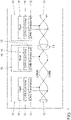
- the bus access method corresponds to the CSMA-CR method (Carrier Sense Multiple Access with Collision Resolution).
- the CSMA/CR procedure ensures that CAN nodes willing to transmit only access the CAN bus when it is free.
- the method of bit-by-bit bus arbitration on which the CSMA/CR procedure is based ensures that the CAN node with the highest-priority CAN message always prevails. In principle, the following applies: the higher the priority of a CAN message, the sooner it can be transmitted on the CAN bus. With an unfavorable system design, low-priority CAN messages even run the risk of not being transmitted at all. That is why the assignment of the IDs is very important for the realization of a deterministic data exchange.
- the 32 bits of the identifier are divided into two areas [message content] and [device].
- the [message content] area includes the high-order bits of the identifier.
- the [Device] area includes the low-order bits of the identifier.
- the size of the individual areas can be selected as required, but must be the same for all participants within a CAN network.
- 24 bits are reserved for the [message content] area and 8 bits for the [device] area. This makes it possible to make a fine differentiation with regard to the priority of messages in the network. If two participants want to send a message with the same priority at the same time, it is decided in the [Device] area which participant has priority.
- a lower binary number in the [message content] or [device] area actually corresponds to a higher priority.
- the dominant bus level always prevails on the CAN bus in the arbitration phase.
- a CAN node that recognizes that it has only sent the recessive bus level but recognizes that the dominant level is present gives up the arbitration.
- the individual bit positions of the arbitration field AF are numbered from 0 to 31 in the upper part of the illustration.
- the priority associated with the individual bit position is also specified for each bit.
- the bit position ID8 has the lowest priority Priority0 in the [message content] area and the bit position ID31 has the highest priority Priority23 in the [message content] area.
- the bit with the number ID0 in the [Device] area has the lowest priority and the bit with the number ID7 has the highest priority.
- the proposed method and associated devices can be implemented in various forms of hardware, software, firmware, special purpose processors or a combination thereof.
- Specialty processors can include Application Specific Integrated Circuits (ASICs), Reduced Instruction Set Computers (RISC), and/or Field Programmable Gate Arrays (FPGAs).
- ASICs Application Specific Integrated Circuits
- RISC Reduced Instruction Set Computers
- FPGAs Field Programmable Gate Arrays
- the proposed method and device is implemented as a combination of hardware and software.
- the software is preferably installed as an application program on a program storage device.
- it is a computer platform based machine that includes hardware such as one or more central processing units (CPU), random access memory (RAM), and one or more input/output (I/O) interfaces.
- An operating system is typically also installed on the computer platform.
- the various processes and functions described here can be part of the application program or a part that is executed via the operating system.
Landscapes
- Engineering & Computer Science (AREA)
- Computer Networks & Wireless Communication (AREA)
- Signal Processing (AREA)
- Theoretical Computer Science (AREA)
- Physics & Mathematics (AREA)
- General Engineering & Computer Science (AREA)
- General Physics & Mathematics (AREA)
- Small-Scale Networks (AREA)
- Probability & Statistics with Applications (AREA)
- Quality & Reliability (AREA)
Description
Die Erfindung betrifft das technische Gebiet der seriellen Datenübertragung zwischen elektronischen Komponenten insbesondere Steuergeräten, Sensoren und Aktoren, die über ein Bussystem vernetzt sind. Solche Steuergeräte werden vielfach in Kraftfahrzeugen eingesetzt. Vernetzte Steuergeräte, Sensoren und Aktoren werden auch in anderen Gebieten der Technik eingesetzt, z.B. in der Automatisierungstechnik, Prozesstechnik, usw. Die Erfindung betrifft ebenso eine entsprechend ausgelegte Busschnittstelle sowie ein entsprechend ausgelegtes Computerprogramm.The invention relates to the technical field of serial data transmission between electronic components, in particular control devices, sensors and actuators that are networked via a bus system. Such control devices are often used in motor vehicles. Networked control devices, sensors and actuators are also used in other areas of technology, e.g. in automation technology, process technology, etc. The invention also relates to a correspondingly designed bus interface and a correspondingly designed computer program.
In modernen Fahrzeugen werden eine Vielzahl von Steuergeräten verbaut. Alleine für den Antriebstrang werden eine Anzahl Steuergeräte eingesetzt, so z.B. Motor-Steuergerät, Getriebe-Steuergerät, ESP-Steuergerät, Fahrwerk-Steuergerät und weitere. Daneben gibt es auch noch weitere Steuergeräte, die im Bereich der Fahrzeugkarosserie verbaut werden und für bestimmte Komfortfunktionen sorgen. Als Beispiele werden genannt die Tür- oder Fensterheber-Steuergeräte, Klimaanlage-Steuergeräte, Sitzverstellungs-Steuergeräte, Airbag-Steuergeräte u.a. Dann gibt es weiterhin Steuergeräte, die zu dem Infotainment-Bereich zählen, wie Kamera-Steuergerät zur Umfeldbeobachtung, Navigationsgerät, RADAR- oder LIDAR-Gerät, Kommunikationsmodul und Entertainmentmodul mit TV, Radio, Video und Musik-Funktion. Insbesondere für den Infotainment-Bereich der fahrzeuginternen Vernetzung von Steuergeräten soll zukünftig IP Kommunikation in Form von IPv6 oder IPv4 zum Einsatz kommen. Dabei werden IP-Pakete übertragen, die eine Länge von bis zu 64 kByte aufweisen können. Zwar können die IP-Pakete segmentiert übertragen werden, jedoch erfordert der Einsatz von IP Kommunikation, dass eine Bustechnologie verwendet wird, die hinreichend große Botschaften übertragen kann. Dabei wird gefordert, dass als MTU (Maximum Transmission Unit), wie sie von Ethernet bekannt sind, mindestens 1280 Byte große Pakete übertragen werden können. Jedoch erfüllen weder der im Kraftfahrzeug eingesetzte klassische CAN Bus 2.0, entsprechend Controller Area Network noch der bereits erweiterte CAN FD Bus, entsprechend Controller Area Network Flexible Data Rate diese Anforderung, da sie Botschaften mit einer maximalen Größe von nur 8 respektive 64 Byte übertragen können. Das macht den Einsatz des CAN-Busses ungeeignet, wenn er die geforderte IPv6 Kommunikation unterstützen soll. Hinsichtlich weiterer Einzelheiten zum IPv6-Protokoll wird auf die Spezifikation RFC 2460 der Internet Engineering Task Force IETF verwiesen.A large number of control units are installed in modern vehicles. A number of control units are used for the drive train alone, such as the engine control unit, transmission control unit, ESP control unit, chassis control unit and others. There are also other control units that are installed in the vehicle body and ensure certain comfort functions. Examples include door or power window control units, air conditioning control units, seat adjustment control units, airbag control units, etc. Then there are also control units that belong to the infotainment area, such as camera control units for monitoring the surroundings, navigation unit, RADAR or LIDAR device, communication module and entertainment module with TV, radio, video and music function. IP communication in the form of IPv6 or IPv4 is to be used in the future, particularly for the infotainment area of in-vehicle networking of control units. IP packets are transmitted that can be up to 64 kbytes long. Although the IP packets can be transmitted in segments, the use of IP communication requires the use of bus technology that can transmit messages of sufficient size. It is required that packets with a size of at least 1280 bytes can be transmitted as MTU (Maximum Transmission Unit), as known from Ethernet. However, neither the classic CAN bus 2.0 used in motor vehicles, corresponding to Controller Area Network, nor the already expanded CAN FD bus, corresponding to Controller Area Network Flexible Data Rate, meet this requirement, as they can transmit messages with a maximum size of only 8 or 64 bytes. This makes the use of the CAN bus unsuitable if it has the required IPv6 communication should support. For further details on the IPv6 protocol, reference is made to the RFC 2460 specification of the Internet Engineering Task Force IETF.
Typischerweise werden die Steuergeräte der verschiedenen Kategorien jeweils mit einem separaten, für die Gerätekategorie entsprechend ausgelegten Bus vernetzt. Es können daher mehrere verschiedene Bussysteme im Fahrzeug eingesetzt werden. Die verschiedenen Bussysteme können dabei über Gateways miteinander verbunden sein, um einen Datenaustausch zu ermöglichen. Im Bereich der Antriebstrang-Steuergeräte wird typischerweise der CAN-Bus eingesetzt, ebenfalls im Bereich der Komfort-Steuergeräte. Im Infotainment-Bereich kommen auch andere Bussysteme zum Einsatz, wie Bussysteme die auf Ethernet-Technologie beruhen, z.B. AVB (Audio Video Bridging) der auf der Standard-Familie nach IEEE 802.1 Standard basiert. Auch Bussysteme, bei denen die Datenübertragung über Lichtwellenleiter geschieht, sind einsetzbar. Als Beispiele werden genannt der MOST Bus (Media Oriented System Transport) oder der D2B Bus (Domestic Digital Bus).Typically, the control units of the different categories are networked with a separate bus that is appropriately designed for the device category. Therefore, several different bus systems can be used in the vehicle. The various bus systems can be connected to one another via gateways in order to enable data exchange. The CAN bus is typically used in the area of powertrain control units, as well as in the area of convenience control units. Other bus systems are also used in the infotainment area, such as bus systems based on Ethernet technology, e.g. AVB (Audio Video Bridging) based on the IEEE 802.1 standard family. Bus systems in which data is transmitted via optical fibers can also be used. The MOST bus (Media Oriented System Transport) or the D2B bus (Domestic Digital Bus) are mentioned as examples.
Es gibt die Möglichkeit über CAN 2.0 oder CAN FD ein Transportprotokoll wie ISO TP als Zwischenschicht zu verwenden, um IPv6 Pakete zu übertragen. Dies hat jedoch einige Nachteile.It is possible to use a transport protocol such as ISO TP as an intermediate layer via CAN 2.0 or CAN FD in order to transmit IPv6 packets. However, this has some disadvantages.
Die Verwendung des Transportprotokolls ISO TP für die Übertragung von IP-Paketen hat den wesentlichen Nachteil, dass sich dadurch die Notwendigkeit der Segmentierung ergibt. Dies erhöht die Fehleranfälligkeit und verursacht einen Overhead bei der Übertragung der Daten. Dieser Overhead wird zum einen durch das Transportprotokoll selbst verursacht. Zum anderen wird ein Großteil des Overheads durch das CAN FD Protokoll selbst verursacht. Jeder CAN FD Übertragungsrahmen besteht aus einer Arbitrierungsphase, in der Bits mit langsamer Datenrate übertragen werden und einer Datenphase, in der die angegebene schnelle Datenrate tatsächlich genutzt werden kann. Dementsprechend kann die hohe Datenrate der Datenphase umso weniger genutzt werden, je häufiger die Arbitrierungsphase auftritt. Dieser Nachteil ist umso schwerwiegender, da die erreichbaren Datenraten bei der CAN Bus Technologie wegen des besonderen Buszugriffsverfahrens ohnehin begrenzt sind.The main disadvantage of using the ISO TP transport protocol for the transmission of IP packets is that segmentation is required. This increases the susceptibility to errors and causes overhead when transferring the data. On the one hand, this overhead is caused by the transport protocol itself. On the other hand, a large part of the overhead is caused by the CAN FD protocol itself. Each CAN FD transmission frame consists of an arbitration phase, in which bits are transmitted at a slow data rate, and a data phase, in which the specified fast data rate can actually be used. Accordingly, the more frequently the arbitration phase occurs, the less the high data rate of the data phase can be used. This disadvantage is all the more serious since the data rates that can be achieved with CAN bus technology are limited anyway due to the special bus access method.
Ein weiterer wesentlicher Nachteil der Verwendung von ISO TP ist, dass gemäß ISO TP zustandsbehaftete Punkt-zu-Punkt Verbindungen verwendet werden, um Daten zu übertragen. Dies verbietet den Einsatz der Multicast-Funktionalitäten des IPv6-Standards. Auf der anderen Seite verliert man die positive Eigenschaft, dass IPv6 Pakete zustandslos sind und unabhängig von anderen IPv6 Paketen übertragen werden können. Bei der Verwendung von ISO TP hängt die Übertragung eines IPv6 Paketes davon ab, ob das vorhergehende Paket erfolgreich übertragen wurde.Another major disadvantage of using ISO TP is that according to ISO TP stateful point-to-point connections are used to transfer data. This prohibits the use of the multicast functionalities of the IPv6 standard. On the other hand, one loses the positive property that IPv6 packets are stateless and can be transmitted independently of other IPv6 packets. When using ISO TP hangs the transmission of an IPv6 packet depends on whether the previous packet was successfully transmitted.
Ein weiterer Nachteil bei der Verwendung von ISO TP zur Ermöglichung von IPv6 Kommunikation über CAN FD ist, dass sich durch das Prinzip mit zustandsbehafteten Punkt-zu-Punkt Verbindungen sehr lange Latenzzeiten bei der Übertragung von Daten ergeben. Das ist für Echtzeit-Anwendungen, bei denen es auf kurze Reaktionszeiten ankommt, ungeeignet. Bisher wird im Kfz-Bereich kaum IPv6 Kommunikation eingesetzt, da dies einen hohen Ressourcenaufwand bedeutet. Der übliche Ansatz IPv6 Kommunikation zu ermöglichen besteht darin als Vernetzungstechnologie die für den Kfz-Bereich teure Ethernet-Technologie einzusetzen.Another disadvantage of using ISO TP to enable IPv6 communication via CAN FD is that the principle with stateful point-to-point connections results in very long latency times when transferring data. This is unsuitable for real-time applications where short reaction times are important. So far, hardly any IPv6 communication has been used in the automotive sector, as this means a lot of resources. The usual approach to enabling IPv6 communication is to use Ethernet technology, which is expensive for the automotive sector, as the networking technology.
Aus der ISO-Norm ISO 11898-1 2015-12-00 "Road vehicles - Controller area network (CAN) - Part 1: Data link layer and physical signalling" ist ein Übertragungsrahmen mit einem Arbitrierungsfeld und einem Datenfeld bekannt, bei dem für die Arbitrierungsphase eine niedrige Bitrate eingestellt wird und für die Übertragung der Daten im Datenfeld eine erhöhte Bitrate eingestellt wird. Die Anzahl der Datenbytes ist für klassische Übertragungsrahmen mit maximal 8 Bytes festgelegt. Dazwischen sind alle Werte erlaubt. Für FD Übertragungsrahmen sind maximal 64 Bytes im Datenfeld erlaubt. Hier sind auch Werte von 12, 16, 20, 24, 32, oder 48 Datenbytes möglich.From the ISO standard ISO 11898-1 2015-12-00 "Road vehicles - Controller area network (CAN) - Part 1: Data link layer and physical signaling" a transmission frame with an arbitration field and a data field is known in which for the A low bit rate is set in the arbitration phase and an increased bit rate is set for the transmission of the data in the data field. The number of data bytes is specified for classic transmission frames with a maximum of 8 bytes. All values in between are allowed. A maximum of 64 bytes are permitted in the data field for FD transmission frames. Values of 12, 16, 20, 24, 32 or 48 data bytes are also possible here.
Aus der
Aus der
Aus der
Aus der
Aus der
Die Erfindung setzt sich zum Ziel die beschriebenen Nachteile bei der Einführung von IP-Kommunikation im Kfz-Bereich zu vermeiden.The aim of the invention is to avoid the disadvantages described when introducing IP communication in the motor vehicle sector.
Diese Aufgabe wird durch ein Verfahren zur Übertragung von Daten über einen seriellen Kommunikationsbus, eine entsprechend ausgelegte Busschnittstelle sowie ein entsprechend ausgelegtes Computerprogramm gelöst.This object is achieved by a method for transmitting data via a serial communication bus, an appropriately designed bus interface and an appropriately designed computer program.
Die abhängigen Ansprüche beinhalten vorteilhafte Weiterbildungen und Verbesserungen der Erfindung entsprechend der nachfolgenden Beschreibung dieser Maßnahmen.The dependent claims contain advantageous developments and improvements of the invention according to the following description of these measures.
Für die Lösung der Aufgabe wird der Ansatz verfolgt das im Kfz-Bereich dominierende CAN Protokoll selbst inkompatibel weiterzuentwickeln um es für die IP Kommunikation tauglich zu machen. Dabei wird im Folgenden das hier neu vorgeschlagene erweiterte CAN Protokoll kurz als CAN EL Protokoll bezeichnet.To solve the task, the approach taken is to further develop the CAN protocol, which is dominant in the automotive sector, to make it suitable for IP communication. In the following, the newly proposed extended CAN protocol is referred to as the CAN EL protocol for short.
Die erste Maßnahme mit der das bestehenden CAN FD Protokoll weiterentwickelt wird, besteht darin bei einem Verfahren zur Übertragung von Daten über einen seriellen Kommunikationsbus, bei dem die Daten mit einem Übertragungsrahmen übertragen werden, wobei der Übertragungsrahmen wenigstens ein Arbitrierungs-Feld und ein Daten-Feld aufweist, dass die Länge des Datenfeldes im Übertragungsrahmen drastisch erweitert wird. Dabei dient das Arbitrierungs-Feld zur Regelung des Buszugriffs nach dem CSMA-CR Verfahren, entsprechend Carrier Sense Multiple Access with Collision Resolution durch Priorisierung der Botschaften mit Hilfe eines Identifizierers. Wie beim CAN FD Bus wird für die Arbitrierungsphase eine niedrige Bitrate eingestellt und für die Übertragung der Daten im Datenfeld eine erhöhte Bitrate eingestellt. Durch die Verlängerung des Nutzdaten-Feldes wird der Nachteil, dass bei dem CAN FD Bus wegen der dort festgelegten Beschränkung der Länge des Nutzdaten-Feldes auf maximal 64 Byte der Vorteil der höheren Bitrate kaum ausgenutzt wird, bei dem hier vorgeschlagenen erweiterten CAN EL Bus vermieden. Die Maßnahme bietet den Vorteil einer deutlich gesteigerten Datenrate/Bandbreite bei der Datenübertragung. Dies bedeutet auch eine signifikant verbesserte Effizienz bei der Übertragung großer Datenpakete. Gleichzeitig wird die bei dem CAN FD Bus vorhandene Beschränkung, dass innerhalb des Nutzdatenfeldes mit maximaler Größe von 64 Bytes nur bestimmte Anzahlen von Bytes möglich sind, aufgehoben. Die Nutzungsmöglichkeiten sind dadurch noch flexibler.The first measure with which the existing CAN FD protocol is further developed is a method for transmitting data via a serial communication bus, in which the data is transmitted with a transmission frame, the transmission frame having at least one arbitration field and one data field exhibits that the length of the data field in the transmission frame is drastically increased. The arbitration field is used to regulate bus access according to the CSMA-CR method, corresponding to Carrier Sense Multiple Access with Collision Resolution by prioritizing the messages with the help of an identifier. As with the CAN FD bus, a low bit rate is set for the arbitration phase and an increased bit rate is set for the transmission of the data in the data field. By lengthening the user data field, the disadvantage that the advantage of the higher bit rate is hardly exploited in the CAN FD bus due to the limitation of the length of the user data field to a maximum of 64 bytes specified there is avoided in the extended CAN EL bus proposed here . The measure offers the advantage of a significantly increased data rate/bandwidth during data transmission. This also means one significantly improved efficiency when transferring large data packets. At the same time, the limitation existing in the CAN FD bus, that only a certain number of bytes are possible within the user data field with a maximum size of 64 bytes, is lifted. This makes the possible uses even more flexible.
Zusätzlich wird im Übertragungsrahmen ein Ende-Feld vorgesehen und in das Ende-Feld wenigstens ein End-of-Frame-Code eingetragen, wobei der End-of-Frame-Code eine Länge von 11 Bit aufweist.In addition, an end field is provided in the transmission frame and at least one end-of-frame code is entered in the end-field, the end-of-frame code having a length of 11 bits.
Diese Maßnahme ist bei einer veränderten Bitstuffing Regel von Vorteil. Durch Senden des End-of-Frame Codes wird eine Verletzung einer neuen Bitstuffing-Regel erzwungen, so dass Teilnehmer, die nicht korrekt synchronisiert waren, diese Tatsache erkennen und den CAN-Controller zurücksetzen können um wieder korrekt synchronisiert zu werden.This measure is advantageous if the bit stuffing rule has changed. By sending the end-of-frame code, a violation of a new bit stuffing rule is enforced, so that participants that were not correctly synchronized can recognize this fact and reset the CAN controller to be correctly synchronized again.
Die Variabilität der Länge des Nutzdatenfeldes garantiert viele Einsatzmöglichkeiten. So braucht kein Kompromiss eingegangen zu werden, wenn es je nach Anwendungsfall auf eine hohe Nettodatenrate ankommt oder in einem anderen Fall mehr die Echtzeitfähigkeit im Vordergrund steht und es mehr auf geringe Latenzzeiten ankommt.The variability of the length of the user data field guarantees many possible uses. So no compromises need to be made if, depending on the application, a high net data rate is important or, in another case, real-time capability is more important and low latency times are more important.
Dabei ist es besonders vorteilhaft, wenn für die variable Länge des Daten-Feldes ein Bereich von 0 bis 4096 Bytes spezifiziert wird. Dies ermöglicht eine gute Interoperabilität mit der heute vielfach zur Anwendung kommenden 1 GBit-Ethernet Variante. Ein Routing zwischen einem Teil des Kfz-Netzwerks wo die 1 GBit Ethernet Bus Variante zum Einsatz kommt, wäre dann ohne Segmentierung möglich. Der Einsatz von IP Kommunikation wird dadurch problemlos möglich.It is particularly advantageous if a range from 0 to 4096 bytes is specified for the variable length of the data field. This enables good interoperability with the 1 GBit Ethernet variant that is widely used today. Routing between a part of the vehicle network where the 1 GBit Ethernet bus variant is used would then be possible without segmentation. This makes it possible to use IP communication without any problems.
Es ist ebenfalls von Vorteil, wenn die Länge des auf 32 Bit festgelegt wird. Bei dem CAN FD Standard wurde eine Länge von 29 Bit für dieses Feld festgelegt. Diese Maßnahme vereinfacht die Hardwareentwicklung für den erweiterten CAN EL Bus. Die heute üblichen Registerlängen sind typischerweise ein Vielfaches von einem Byte, d.h. ein Vielfaches von 8 Bit.It is also beneficial if the length of the is set to 32 bits. A length of 29 bits was specified for this field in the CAN FD standard. This measure simplifies the hardware development for the extended CAN EL bus. The register lengths that are common today are typically a multiple of one byte, i.e. a multiple of 8 bits.
Weiterhin vorteilhaft ist, wenn wie beim CAN FD Protokoll im Übertragungsrahmen ein Steuerungs-Feld zwischen Arbitrierungs-Feld und Daten-Feld vorgesehen wird, in dem wenigstens ein Abschnitt für die Längenangabe bzgl. des Daten-Feldes vorgesehen wird. Hier ist also eine Verlängerung dieses Abschnitts erforderlich um die volle Länge von 4096 Bytes angeben zu können. Dafür sind 13 Bits nötig.It is also advantageous if, as in the case of the CAN FD protocol, a control field is provided in the transmission frame between the arbitration field and the data field, in which at least one section is provided for specifying the length of the data field. So here an extension of this section is necessary in order to be able to specify the full length of 4096 bytes. This requires 13 bits.
Wie beim CAN 2.0 Protokoll und CAN FD Protokoll ist es vorteilhaft, wenn im Übertragungsrahmen ein CRC-Feld vorgesehen wird, in dem wenigstens ein Abschnitt für einen CRC-Prüfcode vorgesehen wird. Der CRC Prüfcode dient zur Fehlerdetektion entsprechend des bekannten Cyclic Redundancy Check Algorithmus.As with the CAN 2.0 protocol and CAN FD protocol, it is advantageous if a CRC field is provided in the transmission frame, in which at least one section is provided for a CRC check code. The CRC check code is used to detect errors according to the well-known Cyclic Redundancy Check algorithm.
Dabei ist es wie beim CAN FD Protokoll von Vorteil, wenn im Übertragungsrahmen ein Start-Feld vorgesehen wird und der CRC-Prüfcode über die Felder Start-Feld, Arbitrierungs-Feld, Steuerungs-Feld und Daten-Feld berechnet wird.As with the CAN FD protocol, it is advantageous if a start field is provided in the transmission frame and the CRC check code is calculated using the start field, arbitration field, control field and data field.
Das Gleiche gilt für den Einsatz des Bit-Stuffing Verfahrens, das ebenfalls schon beim CAN 2.0 Protokoll und CAN FD Protokoll zum Einsatz kam. Hier ist es vorteilhaft, dass die Übertragung der Daten asynchron erfolgt und zur Gewährleistung des Gleichtaktes von Datensende-Station und Datenempfangs-Station eine Resynchronisation nach einer Bitstuffing-Regel durchgeführt wird, wobei die Bitstuffing-Regel über die Bereiche vom Start-Feld bis zum Ende des Daten-Feldes angewendet wird, wobei die Anzahl der eingefügten Stuff-Bits zur Kontrolle in einem Abschnitt des CRC-Feldes eingetragen wird. Durch die Einfügung eines Stuff-Bits wird ein Flankenwechsel auf dem Bus erzwungen, welcher im CAN-Controller zur Resynchronisation des Taktgebers dient, der den Abtasttakt für die Bitrückgewinnung beim Empfang von Daten vorgibt. Dabei wir eine modifizierte Bitstuffing-Regel eingesetzt. Der Bitstuffing Algorithmus (Frame Encoding) wird für das neue Übertragungsformat insofern abgewandelt, dass ein Stuffbit nicht wie bei CAN 2.0 und CAN FD nach 5 sondern erst nach 10 unmittelbar aufeinander folgenden Bits mit dem gleichen Bus-Pegel eingefügt wird. Es werden dadurch weniger "Overhead"-Bits im Datenrahmen benötigt und es wird dadurch die Effizienz der Datenübertragung gesteigert.The same applies to the use of the bit stuffing method, which was also used in the CAN 2.0 protocol and CAN FD protocol. It is advantageous here for the data to be transmitted asynchronously and for the data-transmitting station and data-receiving station to be synchronized, resynchronization is carried out according to a bit stuffing rule, with the bit stuffing rule covering the areas from the start field to the end of the data field is applied, with the number of inserted stuff bits being entered in a section of the CRC field for checking purposes. The insertion of a stuff bit forces an edge change on the bus, which is used in the CAN controller to resynchronize the clock generator that specifies the sampling clock for bit recovery when data is received. A modified bit stuffing rule is used for this. The bit stuffing algorithm (frame encoding) is modified for the new transmission format in that a stuff bit is not inserted after 5, as in CAN 2.0 and CAN FD, but only after 10 consecutive bits with the same bus level. As a result, fewer "overhead" bits are required in the data frame and the efficiency of the data transmission is increased as a result.
Im CRC-Feld wird die Bitstuffing Regel nach dem erweiterten Protokoll nicht eingesetzt. Deshalb ist es zusätzlich von Vorteil, wenn im CRC-Feld an fest vorgegebenen Positionen ein Stuff-Bit zwangsweise eingefügt wird. So werden auch im CRC-Feld Flankenwechsel garantiert und die CAN-Controller der Busteilnehmer bleiben synchronisiert.The bit stuffing rule according to the extended protocol is not used in the CRC field. It is therefore an additional advantage if a stuff bit is forcibly inserted at fixed positions in the CRC field. This also guarantees edge changes in the CRC field and the CAN controllers of the bus participants remain synchronized.
In einem bevorzugten Beispiel beginnt das CRC-Feld mit einem fest vorgegebenen Stuff-Bit und die weiteren fest vorgegebenen Stuff-Bits werden im Abstand von jeweils 9 Bits des CRC-Feldes eingefügt. Das fest vorgegebene Stuff-Bit ist dabei komplementär zu seinem Vorgänger-Bit.In a preferred example, the CRC field begins with a fixed stuff bit and the other fixed stuff bits are inserted at intervals of 9 bits of the CRC field. The predefined stuff bit is complementary to its predecessor bit.
Eine besonders vorteilhafte Maßnahme betrifft die Vergabe der Identifizierer im Arbitirierungs-Feld für die Priorisierung der Botschaften. Demnach wird der Identifizierer im Arbitrierungs-Feld in die Bereiche "Botschafts-Inhalt"-Identifizierer und "Geräte"-Identifizierer unterteilt. Durch die entsprechende Vergabe der Geräte ID kann einem Busteilnehmer die Priorität gegenüber den anderen Busteilnehmern eingeräumt werden. Dadurch wird das Netzwerkverhalten planbar/vorhersagbar und damit echtzeitfähig. Randbedingung ist, dass jedem Gerät ein eindeutiger Geräte-Identifizierer zugewiesen wird.A particularly advantageous measure relates to the assignment of identifiers in the arbitration field for prioritizing the messages. Accordingly, the identifier in the arbitration field is divided into the areas "message content" identifier and "device" identifier. By assigning the device ID accordingly, a bus user can be given priority over the other bus users. This makes the network behavior plannable/predictable and thus real-time capable. The constraint is that each device is assigned a unique device identifier.
Dabei ist es von Vorteil, wenn der Abschnitt mit den höherwertigen Bits für die Priorisierung des Botschafts-Inhaltes reserviert wird und der Abschnitt mit den niederwertigen Bits für die Geräte-Identifizierung vorgesehen werden. Dadurch entscheidet sich der Buszugriff, wie beim CAN-Bus, während der Arbitirierungsphase vorwiegend über die mit verschiedener Priorität versehenen Botschaftsinhalte und erst in zweiter Linie über die Geräte ID.It is advantageous here if the section with the higher-order bits is reserved for prioritizing the message content and the section with the lower-order bits is provided for device identification. As with the CAN bus, bus access is decided during the arbitration phase primarily via the message contents, which have different priorities, and only secondarily via the device ID.
In einer vorteilhaften Variante wird ein 32 Bit langer-Identifizierer so aufgeteilt, dass 24 Bit für die Priorisierung des Botschafts-Inhaltes reserviert werden und 8 Bit für die Priorisierung des Gerätes vorgesehen werden.In an advantageous variant, a 32-bit identifier is divided in such a way that 24 bits are reserved for prioritizing the message content and 8 bits are provided for prioritizing the device.
Zusammengefasst wird durch die vorgestellten Maßnahmen das CAN-FD Protokoll in einer vorteilhaften Weise erweitert, so dass die niedrigen Hardware-Kosten, wie beim CAN-FD Bus gegeben, beibehalten werden können. Auch das für den Kfz-Bereich so essentielle dezentrale Arbitrierungsverfahren wird beibehalten. Dies ist für die weitere Automobilentwicklung eine Erleichterung, da keine neuen Herstellerübergreifenden Spezifizierungen in diesem Bereich notwendig werden. Durch die Beibehaltung der dezentralen Arbitrierung und die besondere Ausgestaltung des Arbitrierungsfeldes bleibt der erweiterte CAN EL Bus echtzeitfähig, was für den Einsatz im Kfz so wichtig ist.In summary, the measures presented expand the CAN FD protocol in an advantageous manner, so that the low hardware costs, as is the case with the CAN FD bus, can be maintained. The decentralized arbitration process, which is so essential for the automotive sector, will also be retained. This is a relief for further automobile development, as no new manufacturer-independent specifications are necessary in this area. By retaining the decentralized arbitration and the special design of the arbitration field, the extended CAN EL bus remains real-time capable, which is so important for use in vehicles.
Durch die bei der Spezifizierung des erweiterten CAN EL Bus-Protokolls eingebaute Variabilität ist das Bus-Protokoll anpassungsfähig an die konkrete Busarchitektur. Je nach geplanter Netzwerkgröße kann die Datenrate angepasst werden, um so eine kostenoptimale Architektur umsetzen zu können. Beispielsweise kann der erweiterte Bus sogar den Sonderfall eines kleinen Netzwerkes mit nur 2 Teilnehmern (Punkt zu Punkt Verbindung) abdecken. Dabei könnte die Datenübertragung mit sehr hoher Datenrate realisiert werden.Due to the variability built into the specification of the extended CAN EL bus protocol, the bus protocol can be adapted to the specific bus architecture. Depending on the planned network size, the data rate can be adjusted in order to be able to implement a cost-optimal architecture. For example, the extended bus can even cover the special case of a small network with only 2 participants (point-to-point connection). In this case, the data transmission could be realized with a very high data rate.
Für eine entsprechend ausgelegte Busschnittstelle zur Verwendung bei dem vorgeschlagenen Verfahren zur Übertragung von Daten über einen seriellen Kommunikationsbus gelten die entsprechenden Vorteile wie im Zusammenhang mit den entsprechenden Verfahrensschritten erläutert.The following apply to a correspondingly designed bus interface for use in the proposed method for transmitting data via a serial communication bus corresponding advantages as explained in connection with the corresponding process steps.
Das Gleiche gilt für ein entsprechend ausgelegtes Computerprogramm, das bei Abarbeitung in einer Recheneinheit die sendeseitigen Schritte und/oder die empfangsseitigen Schritte des vorgeschlagenen Verfahrens zur Übertragung von Daten durchführt. Zwar spielen im Kfz-Bereich die Hardwarekosten eine zentrale Rolle, so dass hier hauptsächlich weniger leistungsfähige Mikrocontroller eingesetzt werden, die durch separate CAN-Controller unterstützt werden, bei denen das Datenübertragungsprotokoll durch Spezial-Hardware realisiert wird. In anderen Bereichen, z.B. im Feldbusbereich für Automatisierungstechnik oder Prozesstechnik werden auch leistungsfähigere Mikrocontroller eingesetzt, für die dann auch die Softwarelösung zur Implementierung des erweiterten Datenübertragungsprotokolls in Betracht kommt.The same applies to a correspondingly designed computer program which, when processed in a computing unit, carries out the steps on the transmission side and/or the steps on the reception side of the proposed method for transmitting data. The hardware costs play a central role in the automotive sector, so that mainly less powerful microcontrollers are used here, which are supported by separate CAN controllers in which the data transmission protocol is implemented by special hardware. In other areas, e.g. in the fieldbus area for automation technology or process technology, more powerful microcontrollers are also used, for which the software solution for implementing the extended data transmission protocol can also be considered.
Ein Ausführungsbeispiel der Erfindung ist in den Zeichnungen dargestellt und wird nachfolgend anhand der Figuren näher erläutert.An embodiment of the invention is shown in the drawings and is explained in more detail below with reference to the figures.
Es zeigen:
- Fig. 1
- das Prinzip der Vernetzung von elektronischen Komponenten mittels CAN-Bus;
- Fig. 2
- ein Blockdiagramm für ein Fahrzeug-Bordnetzwerk mit Steuergeräten verschiedener Kategorie;
- Fig. 3
- das detaillierte Übertragungsrahmen-Format gemäß einem Ausführungsbeispiel der Erfindung;
- Fig. 4
- das Ergebnis der Berechnung der Nettodatenrate für die Übertragung von Daten in Paketen verschiedener Länge gemäß dem vorgeschlagenen Übertragungsrahmen-Format;
- Fig. 5
- das Ergebnis der Berechnung der Effizienz für die Übertragung von Daten in Paketen verschiedener Länge gemäß dem vorgeschlagenen Übertragungsrahmen-Format; und
- Fig. 6
- ein Beispiel des Ablaufs der Arbitrierungsphase, wenn zwei CAN-Knoten gleichzeitig auf den Bus zugreifen.
- 1
- the principle of networking electronic components using a CAN bus;
- 2
- a block diagram for a vehicle on-board network with control units of different categories;
- 3
- the detailed transmission frame format according to an embodiment of the invention;
- 4
- the result of the calculation of the net data rate for the transmission of data in packets of different lengths according to the proposed transmission frame format;
- figure 5
- the result of the calculation of the efficiency for the transmission of data in packets of different lengths according to the proposed transmission frame format; and
- 6
- an example of how the arbitration phase works when two CAN nodes access the bus at the same time.
Die vorliegende Beschreibung veranschaulicht die Prinzipien der erfindungsgemäßen Offenbarung. Der CAN-Bus wurde schon 1994 standardisiert. Die entsprechende ISO-Norm hat die Nummer ISO 11898. Es gibt eine Norm für den Highspeed-Bereich bis 1 Mbit/s, das ist die Norm ISO 11898-2. Dann gibt es eine Norm für den Lowspeed-Bereich bis 125 kBit/s, das ist die Norm ISO 11898-3. Durch das anwachsende Datenaufkommen ergeben sich immer höhere Buslasten auf den CAN-Bussen. Dies führte zu einer Weiterentwicklung des CAN-Busses. Der erweiterte CAN-Bus ist unter dem Begriff CAN FD-Bus bekannt. FD steht dabei für Flexible Data Rate. Bei dieser CAN-Bus Variante wird die Datenrate umgeschaltet. Für die Arbitrierungsphase bleibt die Datenrate niedrig, wie beim klassischen CAN-Bus. Für die Übertragung der Nutzdaten wird auf eine höhere Datenrate umgeschaltet. Überträgt man die Nutzdaten einer CAN-FD-Botschaft schneller, so verkürzt sich die Dauer der Busbelegung; und die Buslast verringert sich. Wenn die Übertragungsdauer im gleichen Rahmen bleibt wie bei den klassischen CAN-Botschaften, könnten größere Datenmengen mit einer CAN-FD-Botschaft transportiert werden. So wurde es auch bei CAN FD realisiert. Statt des 8 Byte langen Nutzdatenfeldes wird bei CAN FD ein 64 Byte langes Nutzdatenfeld eingesetzt. Die Datenrate steigt für die Übertragung des Nutzdatenfeldes bei einer Umsetzung z.B. von 500 kbit/s auf 2 Mbit/s an.This description illustrates the principles of the inventive disclosure. The CAN bus was standardized in 1994. The corresponding ISO standard has the number ISO 11898. There is a standard for the high-speed range up to 1 Mbit/s, that is the ISO 11898-2 standard. Then there is a standard for the low-speed range up to 125 kbit/s, that is the ISO 11898-3 standard. The increasing amount of data results in ever higher bus loads on the CAN buses. This led to further development of the CAN bus. The extended CAN bus is known under the term CAN FD bus. FD stands for Flexible Data Rate. With this CAN bus variant, the data rate is switched. The data rate remains low for the arbitration phase, as with the classic CAN bus. A higher data rate is used for the transmission of user data. If the user data of a CAN FD message is transmitted faster, the duration of the bus occupancy is reduced; and the bus load decreases. If the transmission time remains within the same framework as with classic CAN messages, larger amounts of data could be transported with a CAN FD message. This is also how it was implemented with CAN FD. Instead of the 8-byte user data field, CAN FD uses a 64-byte user data field. For the transmission of the user data field, the data rate increases with a conversion, for example, from 500 kbit/s to 2 Mbit/s.
Analog zum klassischen CAN-Protokoll, kennt z.B. auch der CAN FD Bus zwei Data-Rahmen-Formate: Standard Frames mit 11 Bit Identifizierer und Extended Frames mit 29 Bit Identifizierer. Damit ist gewährleistet, dass Zusatzprotokolle wie CANopen und SAE J1939 mit entsprechenden Anpassungen auch unter CAN FD weiterexistieren und die beschriebenen Vorteile nutzen können.Analogous to the classic CAN protocol, the CAN FD bus, for example, also knows two data frame formats: standard frames with 11-bit identifiers and extended frames with 29-bit identifiers. This ensures that additional protocols such as CANopen and SAE J1939 continue to exist with appropriate adaptations under CAN FD and can use the advantages described.
Für CAN FD wurde darauf verzichtet ein eigenes Format für Remote Frames einzuführen. Dies ist jedoch bei näherem Hinsehen keine Einschränkung. Wegen des fehlenden Datenfeldes wäre eine Erhöhung der Datenrate wirkungslos. Das CAN-FD-Protokoll erlaubt allerdings, CAN FD Data Frames mit klassischen CAN Remote Frames anzufordern.A separate format for remote frames was not introduced for CAN FD. On closer inspection, however, this is not a limitation. Increasing the data rate would have no effect because of the missing data field. However, the CAN FD protocol allows CAN FD data frames to be requested with classic CAN remote frames.
Um Signalreflektionen zu vermeiden ist die Busleitung 15 an beiden Leitungsenden mit einem Abschlusswiderstand 13 der Größe des Wellenwiderstandes der Busleitung (120 Ohm) abgeschlossen.In order to avoid signal reflections, the
Eine CAN-Schnittstelle setzt sich aus zwei Teilen zusammen: der Kommunikationssoftware und der Kommunikationshardware. Während die Kommunikationssoftware höhere Kommunikationsdienste umfasst, sind die grundlegenden Kommunikationsfunktionen typischerweise in Hardware implementiert: Hier werden zwei Hardware-Komponenten unterschieden: Der CAN-Controller 14 sorgt für die einheitliche Abwicklung des CAN-Kommunikationsprotokolls, und entlastet dadurch den Host 16 auf dem die bereits erwähnte Kommunikationssoftware läuft. Der CAN-Transceiver 12 sorgt für die Ankopplung des CAN-Controllers 14 an den CAN-Bus 15. Er formt die Signale für die Datenübertragung beim Sendevorgang und macht die Signalaufbereitung im Empfangsfall. An diesem prinzipiellen Aufbau ändert sich auch nichts, wenn das CAN FD Busprotokoll eingesetzt wird.A CAN interface consists of two parts: the communication software and the communication hardware. While the communication software includes higher communication services, the basic communication functions are typically implemented in hardware: A distinction is made between two hardware components here: The
Das moderne Kraftfahrzeug kann aber noch weitere Komponenten aufweisen wie Videokameras 105, z.B. als Rückfahrkamera oder als Fahrerüberwachungskamera als auch ein LIDAR- oder RADAR-Gerät für die Realisierung eines Radartempomaten oder zur Realisierung eines Abstandswarnungs- oder Kollisionswarnungsgerätes.However, the modern motor vehicle can also have other components such as
Davon unterschieden wird oft ein Navigationssystem 120, welches ebenfalls im Bereich des Cockpits verbaut wird. Die Route, welche auf einer Karte angezeigt wird, kann natürlich ebenfalls auf dem Display im Cockpit dargestellt werden. Weitere Komponenten, wie eine Freisprecheinrichtung können vorhanden sein, sind aber nicht näher dargestellt. Die Bezugszahl 110 bezeichnet noch eine On-Board Unit. Diese On-Bord Unit 110 entspricht einem Kommunikationsmodul über das das Fahrzeug mobile Daten empfangen und senden kann. Typischerweise handelt es sich hier um ein Mobilfunk-Kommunikationsmodul, z. B. nach dem LTE-Standard. All diese Geräte sind dem Infotainment-Bereich zuzuordnen. Sie werden deshalb über ein auf die speziellen Bedürfnisse dieser Gerätekategorie ausgelegtes Bussystem 102 vernetzt. Dieses Bussystem ist nach dem hier vorgeschlagenen erweiterten CAN EL Bus Standard ausgelegt. Als weiteres Beispiel ist noch ein CAN-Bus 108 gezeigt, der nur die beiden Komponenten Fahrerassistenz-Steuergerät 171 und RADAR-Gerät 172 verbindet. Für diesen CAN Bus wird ebenfalls der erweiterte CAN-EL Bus eingesetzt. Dies zeigt den breiten Einsatzbereich des erweiterten CAN-EL Busses. Ein RADAR-Sensor oder LIDAR-Sensor oder eine Anzahl Kameras und/oder Ultraschall-Sensoren kann schon ein erhöhtes Datenaufkommen verursachen. Diese Anforderungen können mit dem CAN EL Bus wie bereits beschrieben erfüllt werden.A
Zu dem Zweck, das fahrzeugrelevante Sensordaten über die Kommunikationsschnittstelle 110 zu einem anderen Fahrzeug oder zu einem Zentralrechner übertragen werden sollen, ist das Gateway 140 vorgesehen. Dieses ist mit beiden verschiedenen Bussystemen 102 und 104 verbunden. Das Gateway 140 ist dazu ausgelegt die Daten, die es über den CAN-Bus 104 empfängt so umzusetzen, dass sie in das Übertragungsformat des Infotainment-Busses 102 umgesetzt werden, so dass sie in den dort spezifizierten Paketen verteilt werden können. Für die Weiterleitung dieser Daten nach extern, also zu einem anderen Kraftfahrzeug oder zu einem Zentralrechner ist die On-Board-Unit 110 mit der Kommunikationsschnittstelle dazu ausgerüstet, diese Datenpakete zu empfangen und wiederum in das Übertragungsformat des entsprechend eingesetzten Mobilfunkstandards umzusetzen. Wie dargestellt, ist das Gateway 140 als zentrales Gerät sowohl an den Highspeed CAN Bus 104, als auch an den Lowspeed CAN-Bus 106 wie auch an den CAN EL Bus 102 und 108 angeschlossen. Es übernimmt daher alle notwendigen Format-Umsetzungen, wenn Daten zwischen den verschiedenen Bussystemen ausgetauscht werden sollen.
Es sind viele verschiedene einzelne Bits im Übertragungsrahmen nach ISO 11898-1 vorhanden, die Steuerungszwecke erfüllen. Vorbereitend werden die verschiedenen Steuerungsbits mit ihrer Bezeichnung in englischer Sprache in der folgenden Tabelle aufgelistet. Bei der nachfolgenden Erwähnung dieser Bits wird die ausführliche Bezeichnung nicht mehr wiederholt.
Die Darstellung ist dabei so gewählt, dass die einzelnen Bits pro Feld des Übertragungsrahmens jeweils in einer Zeile angegeben sind. Mit erhöhter Datenübertragungsrate werden die Felder Control Field, Data Field und CRC Field übertragen. Die erhöhte Datenübertragungsrate liegt zwischen 2000 KBit/s und 12000 KBit/s. Die Schrittweite zur Einstellung der Datenübertragungsrate beträgt 1000 KBit/s. Für die anderen Teile des Übertragungsrahmens, nämlich "Start Field", "Arbitration Field" und "End Field" gilt nach wie vor die niedrige Datenübertragungsrate, die auch beim CAN FD Bus eingesetzt wird, d.h. die Datenübertragungsrate darf zwischen 500 KBit/s und 1500 KBit/s liegen. Die Schrittweite zur Einstellung der Datenübertragungsrate beträgt hier 250 KBit/s.The representation is chosen in such a way that the individual bits per field of the transmission frame are each specified in one line. The Control Field, Data Field and CRC Field fields are transmitted at an increased data transmission rate. The increased data transfer rate is between 2000 Kbps and 12000 Kbps. The increment for setting the data transmission rate is 1000 Kbit/s. For the other parts of the transmission frame, namely "Start Field", "Arbitration Field" and "End Field", the low data transmission rate that is also used with the CAN FD bus still applies, i.e. the data transmission rate may be between 500 Kbit/s and 1500 Kbit/s lie. The increment for setting the data transmission rate here is 250 Kbit/s.
Abweichend von der genannten Spezifikation wird neu nur noch ein Übertragungsrahmen-Format unterstützt. Das neue Übertragungsrahmen-Format beruht auf dem Format FEFF ("FD Extended Frame Format").Deviating from the specified specification, only one transmission frame format is now supported. The new transmission frame format is based on the FEFF format ("FD Extended Frame Format").
Das Start-Feld SF mit dem SOF-Bit bleibt unverändert.The start field SF with the SOF bit remains unchanged.
Nach dem Start-Feld SF werden das Extension0 Bit und das Extension1 Bit, welche für zukünftige Erweiterungen reserviert sind, in das Arbitrierungs-Feld AF eingefügt. Diese Bits sind in dem FEFF-Format nicht vorhanden. Beide Bits Extension0 und Extension1 werden mit "rezessivem" Buspegel übertragen.After the start field SF, the Extension0 bit and the Extension1 bit, which are reserved for future extensions, are inserted into the arbitration field AF. These bits are not present in the FEFF format. Both bits Extension0 and Extension1 are transmitted with a "recessive" bus level.
Der Abschnitt für den Identifizierer in dem Arbitrierungs-Feld AF wird auf 32 Bit erweitert. Die 32 Bit des Identifizierer Abschnitts werden am Stück übertragen und nicht mehr wie bei CAN FD in 2 verschiedenen Abschnitten. Dementsprechend entfallen auch die sonst zum Zweck der Übertragungsrahmen-Formatsteuerung vorgesehenen Bits SRR, RTR, RRS und IDE.The identifier section in the arbitration field AF is extended to 32 bits. The 32 bits of the identifier section are transmitted in one piece and no longer in 2 different sections as with CAN FD. Accordingly, the bits SRR, RTR, RRS and IDE, which are otherwise provided for the purpose of controlling the transmission frame format, are also omitted.
Im Steuerungs-Feld CF wird der Abschnitt für die Längenangabe des Datenfeldes auf eine Länge von 13 Bit erweitert. In den Bits DL0 bis DL12 wird die Länge des Nutzdatenfeldes in der Anzahl der Bytes angegeben. Damit gibt der numerische Wert in diesem Abschnitt exakt die Anzahl an Bytes im Nutzdatenfeld an. Mit 13 Bit kann die maximale Anzahl von 8192 Bytes kodiert werden. Es kann aber auch jede beliebige andere ganze Zahl in dem Bereich damit kodiert werden. Die Länge des Datenfeldes soll bis zu 4096 Byte umfassen, damit ein entsprechendes Ethernet-Paket darin Platz finden kann. Der Bereich des Control Felds mit der Längenangabe für das Datenfeld DF kann zwar mit 13 Bit mehr Bytes angeben, es wird aber über eine Festlegung auf 4096 Bytes begrenzt.In the control field CF, the section for specifying the length of the data field is extended to a length of 13 bits. The length of the user data field is specified in the number of bytes in bits DL0 to DL12. The numerical value in this section therefore specifies the exact number of bytes in the user data field. The maximum number of 8192 bytes can be encoded with 13 bits. However, any other whole number in the range can also be encoded with it. The length of the data field should be up to 4096 bytes so that a corresponding Ethernet packet can find space in it. The area of the control field with the length specification for the data field DF can specify more bytes with 13 bits, but is limited to 4096 bytes by a specification.
Es dürfen also in das verlängerte Daten-Feld DF innerhalb der festgelegten Obergrenze von 4096 eine beliebige Anzahl von Bytes eingetragen werden.Any number of bytes within the specified upper limit of 4096 can therefore be entered in the extended data field DF.
Die Steuerungsbits FDF, BRS und das reservierte res Bit zwischen und Steuerungs-Feld CF und Daten-Feld DF entfallen. Nur das ESI Bit bleibt an dieser Position als Steuerungs-Bit erhalten.The control bits FDF, BRS and the reserved res bit between and control field CF and data field DF are omitted. Only the ESI bit remains in this position as a control bit.
Das Daten-Feld DF selbst kann variable Länge aufweisen. Hier können je nach dem was eingestellt wird bis maximal 4096 Bytes folgen. Das entspricht einer Länge von 32768 Bits.The data field DF itself can have a variable length. Depending on what is set, a maximum of 4096 bytes can follow here. This corresponds to a length of 32768 bits.
Das CRC-Feld CF in dem der CRC Prüfcode eingetragen wird, wird auf eine CRC Länge von 32 Bit erweitert. Der Prüfcode wird in die Bit-Felder CRC0 bis CRC31 eingetragen.The CRC field CF, in which the CRC check code is entered, is extended to a CRC length of 32 bits. The check code is entered in the bit fields CRC0 to CRC31.
Zur Berechnung des CRC-Prüfcodes wird das Polynom G(x) = x32 + x26 + x23 + x22 + x16 + x12 + x11 + x10 + x8 + x7 + x5 + x4 + x2 + x + 1 verwendet.The polynomial G(x) = x32 + x26 + x23 + x22 + x16 + x12 + x11 + x10 + x8 + x7 + x5 + x4 + x2 + x + 1 is used to calculate the CRC check code.
Dabei entspricht das gewählte Polynom dem Polynom, welches in der Spezifikation IEEE 802.3 für Ethernet verwendet wird.The selected polynomial corresponds to the polynomial used in the IEEE 802.3 specification for Ethernet.
Die CRC Prüfsumme ist vom SOF-Bit bis zum letzten Bit des Stuff Bit Counters (Stuff0) zu berechnen.The CRC checksum is to be calculated from the SOF bit to the last bit of the stuff bit counter (stuff0).
Der Abschnitt Stuff Count im CRC Feld CF wird auf eine Länge von 12 Bit geändert und betrifft die Bits Stuff0 bis Stuff 11. In den Abschnitt Stuff Count wird die Anzahl der in dem Bereich vom SOF-Bit bis zum letzten Bit des Daten-Feldes DF eingefügten Stuffbits eingetragen. Dabei wird die Anzahl der Stuffbits binär kodiert. Der Einsatz des Bit-Stuffing ist gegenüber dem beim CAN-FD Standard eingesetzten Bit-Stuffing allerdings vereinfacht. Auch in diesem Punkt wurde der CAN-EL Bus gegenüber dem CAN-FD Bus optimiert, wie im Folgenden im Einzelnen beschrieben.The Stuff Count section in the CRC field CF is changed to a length of 12 bits and affects bits Stuff0 to
Die Einfügung von Stuffbits dient dem Zweck der Synchronisation bei asynchroner Datenübertragung. Zur Herstellung des Gleichlaufs der Kommunikationspartner dient die von rezessiv nach dominant wechselnde Signalflanke des Startbits SOF einer CAN-Botschaft. Ein Resynchronisationsmechanismus sorgt im Anschluss an das SOF-Bit für die Beibehaltung des Gleichlaufs. Der Resynchronisationsmechanismus basiert auf der Auswertung der von rezessiv nach dominant wechselnden Signalflanken. Damit hier die Synchronisation beibehalten wird, wurde im CAN-Standard der Bitstuffingmechanismus eingefügt. In der ISO Norm ISO 11898-1 ist spezifiziert, dass spätestens nach fünf homogenen Bits ein komplementäres Bit zu übertragen ist, auch dann, wenn nach fünf homogenen Bits ohnehin ein komplementäres Bit folgen würde. Die Lage der Stuffbits ist dem Empfänger aufgrund der Regel bekannt und er kann die Stuffbits ignorieren.The insertion of stuff bits serves the purpose of synchronization with asynchronous data transmission. The signal edge of the start bit SOF of a CAN message, which changes from recessive to dominant, is used to establish synchronization between the communication partners. Following the SOF bit, a resynchronization mechanism ensures that synchronization is maintained. The resynchronization mechanism is based on the evaluation of the signal edges changing from recessive to dominant. So that the synchronization is maintained here, the bit stuffing mechanism was added to the CAN standard. The ISO standard ISO 11898-1 specifies that a complementary bit is to be transmitted after five homogeneous bits at the latest, even if a complementary bit would follow after five homogeneous bits anyway. The position of the stuff bits is known to the recipient due to the rule and he can ignore the stuff bits.
Der Bitstuffing Algorithmus (Frame Encoding) für das neue Übertragungsformat wird insofern abgewandelt, dass ein Stuffbit nicht nach 5 sondern erst nach 10 unmittelbar aufeinander folgenden Bits mit dem gleichen Bus-Pegel eingefügt wird. Es werden dadurch weniger Overhead-Bits im Datenrahmen benötigt und es wird dadurch die Effizienz der Datenübertragung gesteigert.The bit stuffing algorithm (frame encoding) for the new transmission format is modified in that a stuff bit is not inserted after 5 but only after 10 consecutive bits with the same bus level. As a result, fewer overhead bits are required in the data frame and the efficiency of the data transmission is increased as a result.
Das variable Bitstuffing ist nur für die Bits vom SOF bis zum letzten Bit des Data Feldes DF durchzuführen. Ab dem CRC Feld CF werden vordefinierte Stuffbits (FixedStuffx) verwendet. Die FixedStuff-Bits werden immer nach 9 Bits eingefügt.The variable bit stuffing is only to be carried out for the bits from the SOF to the last bit of the data field DF. Predefined stuff bits (FixedStuffx) are used starting with the CRC field CF. The FixedStuff bits are always inserted after 9 bits.
Es handelt sich um die Bits FixedStuff0, FixedStuff1, FixedStuff2, FixedStuff3, FixedStuff4 und FixedStuff5. Die einzelnen Stuffbits in dem CRC-Feld sind jeweils mit dem entgegengesetzten Pegel des direkt davor übertragenen Bits zu übertragen.These are the bits FixedStuff0, FixedStuff1, FixedStuff2, FixedStuff3, FixedStuff4 and FixedStuff5. The individual stuff bits in the CRC field are each to be transmitted with the opposite level of the bit transmitted directly before it.
Durch diese fest vorgegebenen Stuffbits FixedStuff0, FixedStuff1, FixedStuff2, FixedStuff3, FixedStuff4 und FixedStuff5 wird ein garantierter Flankenwechsel bei der Übertragung an der gewünschten Stelle bewirkt.These permanently specified stuff bits FixedStuff0, FixedStuff1, FixedStuff2, FixedStuff3, FixedStuff4 and FixedStuff5 cause a guaranteed edge change during transmission at the desired point.
Das Bit FixedStuff0 wird zwischen dem letzten Daten Bit und dem Bit Stuff11 übertragen.The FixedStuff0 bit is transferred between the last data bit and the Stuff11 bit.
Das Bit FixedStuff1 wird zwischen dem Bit Stuff3 und dem Bit Stuff2 übertragen.The FixedStuff1 bit is transferred between the Stuff3 bit and the Stuff2 bit.
Das Bit FixedStuff2 wird zwischen dem Bit CRC26 und dem Bit CRC25 übertragen.The FixedStuff2 bit is transferred between the CRC26 bit and the CRC25 bit.
Das Bit FixedStuff3 wird zwischen dem Bit CRC17 und dem Bit CRC16 übertragen.The FixedStuff3 bit is transferred between the CRC17 bit and the CRC16 bit.
Das Bit FixedStuff4 wird zwischen dem Bit CRC8 und dem Bit CRC7 übertragen.The FixedStuff4 bit is transferred between the CRC8 bit and the CRC7 bit.
Das Bit FixedStuff5 wird zwischen dem Bit CRC0 und dem Bit CRCDel übertragen.The FixedStuff5 bit is transferred between the CRC0 bit and the CRCDel bit.
Das CRCDel Bit, was die Funktion eines CRC Delimiters innehat, bleibt unverändert und hat die gleiche Funktion wie im CAN FD Standard.The CRCDel bit, which has the function of a CRC delimiter, remains unchanged and has the same function as in the CAN FD standard.
Im Ende-Feld EF bleiben beide Bits ACK und ACKDel unverändert.Both bits ACK and ACKDel remain unchanged in the end field EF.
Im Ende-Feld EF wird der Abschnitt mit der EOF Kennzeichnung auf 11 Bit erweitert. Hier werden also statt der beim CAN Bus üblichen 7 aufeinander folgenden rezessiven Bits 11 rezessive Bits übertragen. Die Verlängerung des EOF-Symbols ist der Modifikation des Stuffing Algorithmus geschuldet. Erst nach 11 aufeinander folgenden Bits gleichen Buspegels wird die neue Stuffing-Regel verletzt. Dies wird hier ausgenutzt.In the end field EF, the section with the EOF identifier is expanded to 11 bits. Here, 11 recessive bits are transmitted instead of the 7 consecutive recessive bits that are usual with the CAN bus. The lengthening of the EOF symbol is due to the modification of the stuffing algorithm. The new stuffing rule is only violated after 11 consecutive bits of the same bus level. This is used here.
Beim CAN Bus und CAN FD Bus wird zwischen zwei übertragenen Datenrahmen ein sogenanntes Intermission Feld eingefügt. Hier werden nochmals 3 aufeinanderfolgende rezessive Bits IFS2 bis IFS0 übertragen. Daran erkennen die CAN Controller, dass der Bus wieder freigegeben ist. Diese Regel wird auch beim CAN EL Übertragungsformat beibehalten.With the CAN bus and CAN FD bus, a so-called intermission field is inserted between two transmitted data frames. Here again 3 consecutive recessive bits IFS2 to IFS0 are transmitted. This is how the CAN controllers recognize that the bus is enabled again. This rule is also retained with the CAN EL transmission format.
Wie beschrieben, werden 2 verschiedene Bitraten für die Übertragung der Bits im Übertragungsrahmen eingesetzt. Die genaue Umschaltposition ist in der
Die langsamere Bitrate wird als Bit Rate Langsam bezeichnet.The slower bit rate is called Slow Bit Rate.
Die schnellere Bitrate wird als Bit Rate Schnell bezeichnet.The faster bit rate is called Bit Rate Fast.
Für die Bit Rate Langsam wird ein Bereich zwischen 500 KBit/s und 1500 KBit/s festgelegt. Dabei sollen alle Bitraten in 250 KBit/s Schritten unterstützt werden.The Slow Bit Rate is set to range from 500 kbps to 1500 kbps. All bit rates are to be supported in 250 kbit/s increments.
Für die Bit Rate Schnell wird ein Bereich zwischen 2000 KBit/s und 12000 KBit/s festgelegt. Dabei sollen in diesem Bereich alle Bitraten in 1000 KBit/s Schritten unterstützt werden.A range between 2000 kbps and 12000 kbps is set for the Fast Bit Rate. All bit rates in 1000 kbit/s steps should be supported in this area.
Höhere Bitraten für die Bit Rate Langsam und Bit Rate Schnell können optional unterstützt werden.Higher bit rates for the Bit Rate Slow and Bit Rate Fast can optionally be supported.
Eine beispielhafte Berechnung der daraus resultierenden Nettodatenraten ist in
In
Die Festlegung der Identifizierer für die CAN Botschaften unterliegt grundsätzlich keinerlei Beschränkungen.The determination of the identifiers for the CAN messages is not subject to any restrictions.
Unter Berücksichtigung des Ziels, den CAN Bus für die Übertragung von IP-Paketen zu optimieren, ist es hilfreich eine Vergaberichtlinie hinsichtlich der ID-Vergabe anzuwenden. Die Befolgung der Vergaberichtlinie ist insbesondere für den Bereich der IP Kommunikation vorteilhaft.Taking into account the goal of optimizing the CAN bus for the transmission of IP packets, it is helpful to apply an allocation guideline with regard to ID allocation. Compliance with the award guideline is particularly advantageous for the area of IP communication.
Wie beim CAN Bus und CAN FD wird der Identifizierer zur Realisierung eines Priorisierungskonzeptes verwendet. Anhand des Identifizierers entscheidet sich welcher CAN-Knoten sich auf dem Bus durchsetzt. Das Buszugriffsverfahren entspricht dem CSMA-CR Verfahren (Carrier Sense Multiple Access with Collision Resolution). Das CSMA/CR-Verfahren sorgt dafür, dass sendewillige CAN-Knoten erst dann auf den CAN-Bus zugreifen, wenn dieser frei ist. Bei simultanen Buszugriffen sorgt die dem CSMA/CR-Verfahren zugrundeliegende Methode der bitweisen Busarbitrierung dafür, dass sich immer jener CAN-Knoten mit der höchst prioren CAN-Botschaft durchsetzt. Prinzipiell gilt: je höher die Priorität einer CAN-Botschaft, desto eher kann sie auf dem CAN-Bus übertragen werden. Niederpriore CAN-Botschaften laufen bei ungünstigem Systemdesign sogar Gefahr, gar nicht übertragen zu werden. Deshalb ist die Vergabe der IDs sehr wichtig für die Realisierung eines deterministischen Datenaustausches.As with the CAN bus and CAN FD, the identifier is used to implement a prioritization concept. The identifier is used to decide which CAN node will prevail on the bus. The bus access method corresponds to the CSMA-CR method (Carrier Sense Multiple Access with Collision Resolution). The CSMA/CR procedure ensures that CAN nodes willing to transmit only access the CAN bus when it is free. In the case of simultaneous bus accesses, the method of bit-by-bit bus arbitration on which the CSMA/CR procedure is based ensures that the CAN node with the highest-priority CAN message always prevails. In principle, the following applies: the higher the priority of a CAN message, the sooner it can be transmitted on the CAN bus. With an unfavorable system design, low-priority CAN messages even run the risk of not being transmitted at all. That is why the assignment of the IDs is very important for the realization of a deterministic data exchange.
Nach dem neuen Konzept werden die 32 Bit des Identifizierers in zwei Bereiche [Botschafts-Inhalt] und [Gerät] unterteilt.According to the new concept, the 32 bits of the identifier are divided into two areas [message content] and [device].
Der Bereich [Botschafts-Inhalt] umfasst die höherwertigen Bits des Identifizierers. Der Bereich [Gerät] umfasst die niederwertigen Bits des Identifizierers.The [message content] area includes the high-order bits of the identifier. The [Device] area includes the low-order bits of the identifier.
Die Größe der einzelnen Bereiche kann bedarfsgerecht gewählt werden, muss aber innerhalb eines CAN Netzwerks für alle Teilnehmer gleich sein. In einer beispielhaften Ausführungsform werden 24 Bit für den Bereich [Botschafts-Inhalt] reserviert und 8 Bit für den Bereich [Gerät]. Damit ist es möglich eine feine Differenzierung hinsichtlich der Priorität von Botschaften im Netzwerk vorzunehmen. Sollten zwei Teilnehmer zum gleichen Zeitpunkt eine Botschaft mit der gleichen Priorität senden wollen, entscheidet es sich im Bereich [Gerät], welcher Teilnehmer den Vorzug erhält.The size of the individual areas can be selected as required, but must be the same for all participants within a CAN network. In an
Eine niedrigere Binärzahl im Bereich [Botschafts-Inhalt] bzw. [Gerät] entspricht einer tatsächlich höheren Priorität. Auf dem CAN Bus setzt sich in der Arbitrierungsphase immer der dominante Buspegel durch. Ein CAN Knoten, der erkennt, dass er selbst nur den rezessiven Buspegel gesendet hat und aber erkennt, dass der dominante Pegel anliegt, gibt bei der Arbitrierung auf.A lower binary number in the [message content] or [device] area actually corresponds to a higher priority. The dominant bus level always prevails on the CAN bus in the arbitration phase. A CAN node that recognizes that it has only sent the recessive bus level but recognizes that the dominant level is present gives up the arbitration.
Durch die entsprechende Vergabe der Device ID kann einem Busteilnehmer die Priorität gegenüber den anderen Busteilnehmern eingeräumt werden. Dadurch wird das Netzwerk verhalten vorhersagbar und damit echtzeitfähig.By assigning the device ID accordingly, a bus user can be given priority over the other bus users. This makes the network behavior predictable and thus real-time capable.
Im oberen Teil der Darstellung sind die einzelnen Bit Positionen des Arbitirierungs-Feldes AF von 0 bis 31 durchnummeriert. Im [Botschaftsinhalt]-Bereich wird für jedes Bit auch angegeben welche Priorität mit der einzelnen Bit-Position verbunden ist. Der Bit-Position ID8 kommt im [Botschaftsinhalt]-Bereich die niedrigste Priorität Priority0 zu und der Bit-Position ID31 dementsprechend die höchste Priorität Priority23 im [Botschaftsinhalt]-Bereich. Ebenso hat das Bit mit der Nummer ID0 im [Gerät]-Bereich die niedrigste Priorität und das Bit mit der Nummer ID7 dann die höchste Priorität.
The individual bit positions of the arbitration field AF are numbered from 0 to 31 in the upper part of the illustration. In the [message content] area, the priority associated with the individual bit position is also specified for each bit. The bit position ID8 has the lowest priority Priority0 in the [message content] area and the bit position ID31 has the highest priority Priority23 in the [message content] area. Likewise, the bit with the number ID0 in the [Device] area has the lowest priority and the bit with the number ID7 has the highest priority.
Im mittleren Bereich der
Im unteren Bereich der
Die Offenbarung ist nicht auf die hier beschriebenen Ausführungsbeispiele beschränkt. Es gibt Raum für verschiedene Anpassungen und Modifikationen, die der Fachmann aufgrund seines Fachwissens als auch zu der Offenbarung zugehörend in Betracht ziehen würde.The disclosure is not limited to the exemplary embodiments described here. There is room for various adaptations and modifications that those skilled in the art would contemplate based on their skill in the art as well as belonging to the disclosure.
Alle hierin erwähnten Beispiele wie auch bedingte Formulierungen sind ohne Einschränkung auf solche speziell angeführten Beispiele zu verstehen. So wird es zum Beispiel von Fachleuten anerkannt, dass das hier dargestellte Blockdiagramm eine konzeptionelle Ansicht einer beispielhaften Schaltungsanordnung darstellt.All examples mentioned herein, as well as conditional language, are intended to be understood as not being limited to such specifically cited examples. For example, it will be appreciated by those skilled in the art that the block diagram presented herein represents a conceptual view of exemplary circuitry.
Es sollte verstanden werden, dass das vorgeschlagene Verfahren und die zugehörigen Vorrichtungen in verschiedenen Formen von Hardware, Software, Firmware, Spezialprozessoren oder einer Kombination davon implementiert werden können. Spezialprozessoren können anwendungsspezifische integrierte Schaltungen (ASICs), Reduced Instruction Set Computer (RISC) und / oder Field Programmable Gate Arrays (FPGAs) umfassen. Vorzugsweise wird das vorgeschlagene Verfahren und die Vorrichtung als eine Kombination von Hardware und Software implementiert. Die Software wird vorzugsweise als ein Anwendungsprogramm auf einer Programmspeichervorrichtung installiert. Typischerweise handelt es sich um eine Maschine auf Basis einer Computerplattform die Hardware aufweist, wie beispielsweise eine oder mehrere Zentraleinheiten (CPU), einen Direktzugriffsspeicher (RAM) und eine oder mehrere Eingabe/Ausgabe (I/O) Schnittstelle(n). Auf der Computerplattform wird typischerweise außerdem ein Betriebssystem installiert. Die verschiedenen Prozesse und Funktionen, die hier beschrieben wurden, können Teil des Anwendungsprogramms sein, oder ein Teil der über das Betriebssystem ausgeführt wird.It should be understood that the proposed method and associated devices can be implemented in various forms of hardware, software, firmware, special purpose processors or a combination thereof. Specialty processors can include Application Specific Integrated Circuits (ASICs), Reduced Instruction Set Computers (RISC), and/or Field Programmable Gate Arrays (FPGAs). Preferably, the proposed method and device is implemented as a combination of hardware and software. The software is preferably installed as an application program on a program storage device. Typically, it is a computer platform based machine that includes hardware such as one or more central processing units (CPU), random access memory (RAM), and one or more input/output (I/O) interfaces. An operating system is typically also installed on the computer platform. The various processes and functions described here can be part of the application program or a part that is executed via the operating system.
- 1010
- CAN-KnotenCAN node
- 1212
- CAN-TransceiverCAN transceiver
- 1313
- Abschlusswiderstandtermination resistor
- 1414
- CAN-ControllerCAN controller
- 1515
- Busleitungbus line
- 1616
- Hosthost
- 100100
- Kfz-Elektronikautomotive electronics
- 102102
- Infotainment-CAN-BusInfotainment CAN bus
- 104104
- Highspeed CAN-BusHigh speed CAN bus
- 105105
- Kameracamera
- 106106
- Lowspeed CAN-BusLow speed CAN bus
- 108108
- Fahrerassistenz-CAN-BusDriver assistance CAN bus
- 110110
- Kommunikationsmodulcommunication module
- 120120
- Navigationssystemnavigation system
- 131131
- Bedienungseinheitoperating unit
- 132132
- Klimaanlagen-SteuergerätAir conditioning control unit
- 133133
- Wählhebel-Steuergerätselector lever control unit
- 134134
- Türsteuergerätdoor controller
- 140140
- GatewayGateway
- 151151
- Motor-Steuergerätengine control unit
- 152152
- ESP-SteuergerätESP control unit
- 153153
- Getriebe-Steuergerättransmission control unit
- 161161
-
Sensor 1
sensor 1 - 162162
-
Sensor 2
sensor 2 - 163163
-
Sensor 3
sensor 3 - 171171
- Fahrerassistenz-Steuergerätdriver assistance control unit
- 172172
- RADAR-SteuergerätRADAR control unit
- AA
- 1. Beispielkurve1. Example curve
- BB
- 2. Beispielkurve2. Example curve
- CC
- 3. Beispielkurve3. Example curve
- DD
- 4. Beispielkurve4. Example curve
- St. ASt A
- Station AStation A
- St. BSt B
- Station BStation B
- BRSPBRSP
- Bitraten-UmschaltpunktBitrate switching point
Claims (14)
- Method for transmitting data via a serial communications bus in which the data is transmitted with a transmission frame,wherein the transmission frame has at least one arbitration field (AF) and one data field (DF), wherein the arbitration field (AF) serves to regulate the bus access according to the CSMA-CR method, corresponding to carrier sense multiple access with collision resolution, by prioritizing the messages with the aid of an identifier,wherein a low bit rate is configured for the arbitration phase, and an increased bit rate is configured for the transmission of the data in the data field (DF), wherein the data field (DF), within a fixed upper limit that is greater than 64 bytes, has a variable length for an arbitrary number of bytes,characterized in thatan end field (EF) is also provided in the transmission frame, and at least one end-of-frame code is entered in the end field (EF), wherein the end-of-frame code has a length of 11 bits, in order to force an infringement of a new bit-stuffing rule by sending the end-of-frame code so that participants that were not correctly synchronized recognize this fact.
- Method according to claim 1, wherein the set upper limit relates to the value of 4,096 bytes.
- Method according to claim 1 or 2, wherein the length of the arbitration field (AF) is set at 32 bits.
- Method according to one of the preceding claims, wherein, in the transmission frame, between the arbitration field (AF) and the data field (DF), a control field (CF) is provided, in which at least one portion is provided for specifying the length relating to the data field (DF).
- Method according to one of the preceding claims, wherein, in the transmission frame, a CRC field (CRCF) is provided, in which at least one section is provided for the CRC verification code.
- Method according to claim 5, wherein a start field (SF) is provided in the transmission frame, and the CRC verification code is calculated via the fields:
start field (SF), arbitration field (AF), control field (CF), and data field (DF). - Method according to claim 6, wherein the transmission of the data occurs asynchronously, and a resynchronization is performed according to a bit-stuffing rule in order to ensure the common mode of data sending station and data receiving station, wherein the bit-stuffing rule is applied over the regions from the start field (SF) to the end of the data field (DF), wherein the bit-stuffing rule states that a stuff-bit is inserted only after a defined number of immediately consecutive bits having the same bus level, wherein the defined number is a natural number greater than the number 5, wherein the number of inserted stuff-bits is entered in a portion of the CRC field (CRCF).
- Method according to one of the preceding claims, wherein a stuff-bit is inserted in the CRC field (CRCF) at rigidly predetermined positions.
- Method according to claim 8, wherein the CRC field (CRCF) begins with a rigidly predetermined stuff-bit, and the further rigidly predetermined stuff-bits are inserted in each case at an interval of 9 bits of the CRC field (CRCF).
- Method according to one of the preceding claims, wherein the identifier in the arbitration field (AF) is divided into the portions, "message content" identifiers and "devices" identifiers.
- Method according to claim 10, wherein the portion with the higher value bits is reserved for prioritizing the message content, and the portion with the lower value bits is provided for identifying the devices.
- Method according to claim 11, wherein the identifier has a length of 32 bits, and the portion with the higher value bits has a length of 24 bits, and the portion with the lower value bits has a length of 8 bits.
- Bus interface designed for use in the method according to one of the preceding claims.
- Computer program, characterized in that the computer program is designed, when being processed in a computing unit, to carry out the sending steps and/or the receiving steps of the method for transmitting data according to one of claims 1 through 12.
Applications Claiming Priority (2)
| Application Number | Priority Date | Filing Date | Title |
|---|---|---|---|
| DE102017211860.1A DE102017211860B3 (en) | 2017-07-11 | 2017-07-11 | Method for transmitting data via a serial communication bus, appropriately designed bus interface and computer program designed accordingly |
| EP18176209.7A EP3429136B1 (en) | 2017-07-11 | 2018-06-06 | Method for transmitting data via a serial communication bus, correspondingly designed bus interface and corresponding computer program |
Related Parent Applications (2)
| Application Number | Title | Priority Date | Filing Date |
|---|---|---|---|
| EP18176209.7A Division EP3429136B1 (en) | 2017-07-11 | 2018-06-06 | Method for transmitting data via a serial communication bus, correspondingly designed bus interface and corresponding computer program |
| EP18176209.7A Division-Into EP3429136B1 (en) | 2017-07-11 | 2018-06-06 | Method for transmitting data via a serial communication bus, correspondingly designed bus interface and corresponding computer program |
Publications (2)
| Publication Number | Publication Date |
|---|---|
| EP3661131A1 EP3661131A1 (en) | 2020-06-03 |
| EP3661131B1 true EP3661131B1 (en) | 2022-09-07 |
Family
ID=62684587
Family Applications (2)
| Application Number | Title | Priority Date | Filing Date |
|---|---|---|---|
| EP18176209.7A Active EP3429136B1 (en) | 2017-07-11 | 2018-06-06 | Method for transmitting data via a serial communication bus, correspondingly designed bus interface and corresponding computer program |
| EP19218441.4A Active EP3661131B1 (en) | 2017-07-11 | 2018-06-06 | Method for transmitting data via a serial communication bus, bus interface designed for this purpose, and correspondingly designed computer program |
Family Applications Before (1)
| Application Number | Title | Priority Date | Filing Date |
|---|---|---|---|
| EP18176209.7A Active EP3429136B1 (en) | 2017-07-11 | 2018-06-06 | Method for transmitting data via a serial communication bus, correspondingly designed bus interface and corresponding computer program |
Country Status (6)
| Country | Link |
|---|---|
| US (2) | US10530606B2 (en) |
| EP (2) | EP3429136B1 (en) |
| KR (1) | KR102023673B1 (en) |
| CN (1) | CN109240970B (en) |
| DE (1) | DE102017211860B3 (en) |
| ES (1) | ES2929124T3 (en) |
Families Citing this family (18)
| Publication number | Priority date | Publication date | Assignee | Title |
|---|---|---|---|---|
| DE102017211860B3 (en) * | 2017-07-11 | 2018-09-20 | Volkswagen Aktiengesellschaft | Method for transmitting data via a serial communication bus, appropriately designed bus interface and computer program designed accordingly |
| WO2019030214A1 (en) | 2017-08-08 | 2019-02-14 | Volkswagen Aktiengesellschaft | Method for transmitting data via a serial communication bus, correspondingly designed bus interface, and correspondingly designed computer program |
| US10439840B1 (en) * | 2018-07-27 | 2019-10-08 | Nxp B.V. | Method and device for communicating data frames on a multi-master bus |
| DE102018218721A1 (en) * | 2018-10-31 | 2020-04-30 | Robert Bosch Gmbh | Subscriber station for a serial bus system and method for sending a message in a serial bus system |
| DE102018221681A1 (en) * | 2018-12-13 | 2020-06-18 | Robert Bosch Gmbh | Subscriber station for a serial bus system and method for communication in a serial bus system |
| DE102019201316A1 (en) * | 2019-02-01 | 2020-08-06 | Robert Bosch Gmbh | Subscriber station for a serial bus system and method for communication in a serial bus system |
| KR102006634B1 (en) * | 2019-03-06 | 2019-08-02 | 브이에스아이 주식회사 | Method for enabling nodes of hetero-geneous communication protocols to share a single bus by adapting to one of the hetero-geneous communication protocols and devics for said method |
| JP7114515B2 (en) * | 2019-03-14 | 2022-08-08 | 国立大学法人東海国立大学機構 | Communication device, communication system and message arbitration method |
| DE102019204115A1 (en) | 2019-03-26 | 2020-10-01 | Robert Bosch Gmbh | Subscriber station for a serial bus system and method for communication in a serial bus system |
| DE102019213783A1 (en) * | 2019-09-11 | 2021-03-11 | Robert Bosch Gmbh | Subscriber station for a serial bus system and method for communication in a serial bus system |
| DE102019218715A1 (en) * | 2019-12-02 | 2021-06-02 | Robert Bosch Gmbh | Subscriber station for a serial bus system and method for communication in a serial bus system |
| CN111130695B (en) * | 2019-12-10 | 2022-09-20 | 卡斯柯信号有限公司 | Method for calculating CANOPEN protocol CRC through redundant code words |
| KR20210073976A (en) * | 2019-12-11 | 2021-06-21 | 현대자동차주식회사 | Gateway for vehicle and controlling method of thereof |
| US20210255984A1 (en) * | 2020-02-19 | 2021-08-19 | Magna Electronics Inc. | Vehicular sensor testing system with standardized i2c communication |
| GB2592967A (en) * | 2020-03-12 | 2021-09-15 | Warwick Control Tech Ltd | A method for monitoring a network |
| CN112732511B (en) * | 2021-01-14 | 2022-10-25 | 上海镭隆科技发展有限公司 | High-performance high-speed synchronous 422 simulator board card based on HDLC protocol |
| CN112765072A (en) * | 2021-01-28 | 2021-05-07 | 北京方天长久科技股份有限公司 | Serial interconnection bus data frame format and transmission method |
| DE102021206175A1 (en) * | 2021-06-17 | 2022-12-22 | Robert Bosch Gesellschaft mit beschränkter Haftung | Driving system, control module and method of operation |
Family Cites Families (16)
| Publication number | Priority date | Publication date | Assignee | Title |
|---|---|---|---|---|
| JP3042549B2 (en) * | 1991-08-23 | 2000-05-15 | 古河電気工業株式会社 | Multi-transmission method reception response method |
| FI88841C (en) * | 1991-10-30 | 1993-07-12 | Nokia Telecommunications Oy | Method for processing alternate length data transfer frames with a channel controller and for placing them into a cyclic buffer memory |
| US9880956B2 (en) * | 2011-04-06 | 2018-01-30 | Robert Bosch Gmbh | Method and apparatus for adapting the data transmission security in a serial bus system |
| DE102011006884A1 (en) | 2011-04-06 | 2012-10-11 | Robert Bosch Gmbh | Method for transferring serial data in bus system, involves determining size of data field in presence of switching condition, so that values of four bits of data length code partially deviating from specific standard are interpreted |
| CN103562900B (en) * | 2011-04-06 | 2017-02-15 | 罗伯特·博世有限公司 | Method and device for increasing the data transmission capacity in serial bus system |
| EP2521319B1 (en) * | 2011-05-02 | 2015-10-14 | Robert Bosch GmbH | Controller area network with flexible data-rate |
| DE102011122843A1 (en) | 2011-06-29 | 2013-01-31 | Robert Bosch Gmbh | Method for transferring serial data in bus system of motor vehicle, involves integrating information about error passive state of bus into frames by additional bit |
| DE102012224024A1 (en) | 2012-12-20 | 2014-06-26 | Robert Bosch Gmbh | Data transfer using a log exemption state |
| US9419737B2 (en) * | 2013-03-15 | 2016-08-16 | Concio Holdings LLC | High speed embedded protocol for distributed control systems |
| DE102014205120A1 (en) * | 2014-03-19 | 2015-09-24 | Robert Bosch Gmbh | Subscriber station for a bus system and method for increasing the transmission capacity in a bus system |
| CN105593067B (en) * | 2014-04-17 | 2019-07-02 | 松下电器(美国)知识产权公司 | Vehicle netbios, illegal detection electronic control unit and illegal detection method |
| CN116545566A (en) * | 2014-05-26 | 2023-08-04 | 康西欧控股有限公司 | High speed embedded protocol for distributed control system |
| WO2016054245A1 (en) | 2014-09-30 | 2016-04-07 | Concio Holdings LLC | Confirming data accuracy in a distributed control system |
| DE102015204714A1 (en) | 2015-03-16 | 2016-09-22 | Robert Bosch Gmbh | Subscriber station for a bus system and method for data transmission in a bus system |
| US10050983B2 (en) * | 2015-11-13 | 2018-08-14 | Kabushiki Kaisha Toshiba | Communication system, receiving apparatus, receiving method, and computer program product |
| DE102017211860B3 (en) * | 2017-07-11 | 2018-09-20 | Volkswagen Aktiengesellschaft | Method for transmitting data via a serial communication bus, appropriately designed bus interface and computer program designed accordingly |
-
2017
- 2017-07-11 DE DE102017211860.1A patent/DE102017211860B3/en not_active Expired - Fee Related
-
2018
- 2018-06-06 ES ES19218441T patent/ES2929124T3/en active Active
- 2018-06-06 EP EP18176209.7A patent/EP3429136B1/en active Active
- 2018-06-06 EP EP19218441.4A patent/EP3661131B1/en active Active
- 2018-07-06 US US16/029,054 patent/US10530606B2/en active Active
- 2018-07-09 KR KR1020180079333A patent/KR102023673B1/en active IP Right Grant
- 2018-07-10 CN CN201810750576.8A patent/CN109240970B/en active Active
-
2020
- 2020-01-03 US US16/733,902 patent/US11146420B2/en active Active
Also Published As
| Publication number | Publication date |
|---|---|
| EP3661131A1 (en) | 2020-06-03 |
| CN109240970A (en) | 2019-01-18 |
| CN109240970B (en) | 2022-06-03 |
| ES2929124T3 (en) | 2022-11-25 |
| EP3429136A1 (en) | 2019-01-16 |
| KR102023673B1 (en) | 2019-09-23 |
| EP3429136B1 (en) | 2020-03-25 |
| US10530606B2 (en) | 2020-01-07 |
| US20190020499A1 (en) | 2019-01-17 |
| KR20190006922A (en) | 2019-01-21 |
| US20200145254A1 (en) | 2020-05-07 |
| DE102017211860B3 (en) | 2018-09-20 |
| US11146420B2 (en) | 2021-10-12 |
Similar Documents
| Publication | Publication Date | Title |
|---|---|---|
| EP3661131B1 (en) | Method for transmitting data via a serial communication bus, bus interface designed for this purpose, and correspondingly designed computer program | |
| EP3665875B1 (en) | Method for transmitting data via a serial communication bus, correspondingly designed bus interface, and correspondingly designed computer program | |
| DE102018105007B4 (en) | Method for transmitting data via a communication channel, appropriately designed device and communication interface and computer program designed accordingly | |
| EP2702495B1 (en) | Method and device for serial data transmission which is adapted to memory sizes | |
| EP2695075B1 (en) | Method and device for increasing the data transmission capacity in a serial bus system | |
| EP2695074B1 (en) | Method and apparatus for adapting the data transmission security in a serial bus system | |
| EP3248362B1 (en) | Data transmission in a communications network | |
| WO2007051595A1 (en) | Method and system for the transmission of cyclic and acyclic data | |
| WO2020187985A1 (en) | Method for monitoring communication on a communication bus, electronic apparatus for connection to a communication bus, and vehicle | |
| WO2018077528A1 (en) | Detection of manipulations in a can network by checking can identifiers | |
| DE102017012214B4 (en) | Method for transmitting data via a serial communication bus, appropriately designed bus interface and computer program designed accordingly | |
| WO2019057882A1 (en) | Method for monitoring the communication on a communication bus, and electronic apparatus for connection to a communication bus | |
| EP3152872A1 (en) | Transmission unit with checking function | |
| EP3725041A1 (en) | Method for providing information for the localization of errors in a communications network of an apparatus, correspondingly designed bus device station and vehicle | |
| WO2021099186A2 (en) | Method for monitoring communication on a communication bus, electronic device for connection to a communication bus, and central monitoring device for connection to a communication bus | |
| DE102019213322A1 (en) | Ethernet physical layer transceiver for two-wire bus topology | |
| DE102011006884A1 (en) | Method for transferring serial data in bus system, involves determining size of data field in presence of switching condition, so that values of four bits of data length code partially deviating from specific standard are interpreted | |
| WO2012136783A1 (en) | Method and device for transmitting data between connected bus systems | |
| DE102012201669A1 (en) | Method for transferring data between two data processing units, involves modifying unidirectional transmission method opposite to transmission method for network-norm, so that transmission rate is achieved from data processing units | |
| DE102021201120A1 (en) | Subscriber station for a serial bus system and method for communication in a serial bus system | |
| DE102011122801A1 (en) | Method and device for adapting the data transmission security in a serial bus system | |
| DE102011006875A1 (en) | Method for serial transmission of data between programming unit and control device, during manufacturing of motor vehicle, involves using check field of messages with number of bits or polynomial depending on value of condition | |
| WO2020083960A1 (en) | Subscriber station for a serial bus system, and method for transmitting data with manipulation protection in a serial bus system | |
| DE102011017539A1 (en) | Method for serial data transmission between e.g. two control devices of motor vehicle during normal operation of motor vehicle, involves adapting retransmitted data quantity corresponding to size difference between data field and storage | |
| DE102011122826A1 (en) | Method and device for memory data adapted serial data transmission |
Legal Events
| Date | Code | Title | Description |
|---|---|---|---|
| PUAI | Public reference made under article 153(3) epc to a published international application that has entered the european phase |
Free format text: ORIGINAL CODE: 0009012 |
|
| STAA | Information on the status of an ep patent application or granted ep patent |
Free format text: STATUS: THE APPLICATION HAS BEEN PUBLISHED |
|
| AC | Divisional application: reference to earlier application |
Ref document number: 3429136 Country of ref document: EP Kind code of ref document: P |
|
| AK | Designated contracting states |
Kind code of ref document: A1 Designated state(s): AL AT BE BG CH CY CZ DE DK EE ES FI FR GB GR HR HU IE IS IT LI LT LU LV MC MK MT NL NO PL PT RO RS SE SI SK SM TR |
|
| STAA | Information on the status of an ep patent application or granted ep patent |
Free format text: STATUS: REQUEST FOR EXAMINATION WAS MADE |
|
| 17P | Request for examination filed |
Effective date: 20201203 |
|
| RBV | Designated contracting states (corrected) |
Designated state(s): AL AT BE BG CH CY CZ DE DK EE ES FI FR GB GR HR HU IE IS IT LI LT LU LV MC MK MT NL NO PL PT RO RS SE SI SK SM TR |
|
| RIC1 | Information provided on ipc code assigned before grant |
Ipc: G06F 13/42 20060101ALI20220201BHEP Ipc: G06F 13/376 20060101ALI20220201BHEP Ipc: H04L 12/40 20060101ALI20220201BHEP Ipc: H04L 12/413 20060101AFI20220201BHEP |
|
| GRAP | Despatch of communication of intention to grant a patent |
Free format text: ORIGINAL CODE: EPIDOSNIGR1 |
|
| STAA | Information on the status of an ep patent application or granted ep patent |
Free format text: STATUS: GRANT OF PATENT IS INTENDED |
|
| INTG | Intention to grant announced |
Effective date: 20220318 |
|
| RAP3 | Party data changed (applicant data changed or rights of an application transferred) |
Owner name: VOLKSWAGEN AKTIENGESELLSCHAFT |
|
| GRAS | Grant fee paid |
Free format text: ORIGINAL CODE: EPIDOSNIGR3 |
|
| GRAA | (expected) grant |
Free format text: ORIGINAL CODE: 0009210 |
|
| STAA | Information on the status of an ep patent application or granted ep patent |
Free format text: STATUS: THE PATENT HAS BEEN GRANTED |
|
| AC | Divisional application: reference to earlier application |
Ref document number: 3429136 Country of ref document: EP Kind code of ref document: P |
|
| AK | Designated contracting states |
Kind code of ref document: B1 Designated state(s): AL AT BE BG CH CY CZ DE DK EE ES FI FR GB GR HR HU IE IS IT LI LT LU LV MC MK MT NL NO PL PT RO RS SE SI SK SM TR |
|
| REG | Reference to a national code |
Ref country code: GB Ref legal event code: FG4D Free format text: NOT ENGLISH |
|
| REG | Reference to a national code |
Ref country code: CH Ref legal event code: EP Ref country code: AT Ref legal event code: REF Ref document number: 1517980 Country of ref document: AT Kind code of ref document: T Effective date: 20220915 |
|
| REG | Reference to a national code |
Ref country code: IE Ref legal event code: FG4D Free format text: LANGUAGE OF EP DOCUMENT: GERMAN |
|
| REG | Reference to a national code |
Ref country code: DE Ref legal event code: R096 Ref document number: 502018010610 Country of ref document: DE |
|
| REG | Reference to a national code |
Ref country code: ES Ref legal event code: FG2A Ref document number: 2929124 Country of ref document: ES Kind code of ref document: T3 Effective date: 20221125 |
|
| REG | Reference to a national code |
Ref country code: LT Ref legal event code: MG9D |
|
| REG | Reference to a national code |
Ref country code: NL Ref legal event code: MP Effective date: 20220907 |
|
| PG25 | Lapsed in a contracting state [announced via postgrant information from national office to epo] |
Ref country code: SE Free format text: LAPSE BECAUSE OF FAILURE TO SUBMIT A TRANSLATION OF THE DESCRIPTION OR TO PAY THE FEE WITHIN THE PRESCRIBED TIME-LIMIT Effective date: 20220907 Ref country code: RS Free format text: LAPSE BECAUSE OF FAILURE TO SUBMIT A TRANSLATION OF THE DESCRIPTION OR TO PAY THE FEE WITHIN THE PRESCRIBED TIME-LIMIT Effective date: 20220907 Ref country code: NO Free format text: LAPSE BECAUSE OF FAILURE TO SUBMIT A TRANSLATION OF THE DESCRIPTION OR TO PAY THE FEE WITHIN THE PRESCRIBED TIME-LIMIT Effective date: 20221207 Ref country code: LV Free format text: LAPSE BECAUSE OF FAILURE TO SUBMIT A TRANSLATION OF THE DESCRIPTION OR TO PAY THE FEE WITHIN THE PRESCRIBED TIME-LIMIT Effective date: 20220907 Ref country code: LT Free format text: LAPSE BECAUSE OF FAILURE TO SUBMIT A TRANSLATION OF THE DESCRIPTION OR TO PAY THE FEE WITHIN THE PRESCRIBED TIME-LIMIT Effective date: 20220907 Ref country code: FI Free format text: LAPSE BECAUSE OF FAILURE TO SUBMIT A TRANSLATION OF THE DESCRIPTION OR TO PAY THE FEE WITHIN THE PRESCRIBED TIME-LIMIT Effective date: 20220907 |
|
| PG25 | Lapsed in a contracting state [announced via postgrant information from national office to epo] |
Ref country code: HR Free format text: LAPSE BECAUSE OF FAILURE TO SUBMIT A TRANSLATION OF THE DESCRIPTION OR TO PAY THE FEE WITHIN THE PRESCRIBED TIME-LIMIT Effective date: 20220907 Ref country code: GR Free format text: LAPSE BECAUSE OF FAILURE TO SUBMIT A TRANSLATION OF THE DESCRIPTION OR TO PAY THE FEE WITHIN THE PRESCRIBED TIME-LIMIT Effective date: 20221208 |
|
| PG25 | Lapsed in a contracting state [announced via postgrant information from national office to epo] |
Ref country code: SM Free format text: LAPSE BECAUSE OF FAILURE TO SUBMIT A TRANSLATION OF THE DESCRIPTION OR TO PAY THE FEE WITHIN THE PRESCRIBED TIME-LIMIT Effective date: 20220907 Ref country code: RO Free format text: LAPSE BECAUSE OF FAILURE TO SUBMIT A TRANSLATION OF THE DESCRIPTION OR TO PAY THE FEE WITHIN THE PRESCRIBED TIME-LIMIT Effective date: 20220907 Ref country code: PT Free format text: LAPSE BECAUSE OF FAILURE TO SUBMIT A TRANSLATION OF THE DESCRIPTION OR TO PAY THE FEE WITHIN THE PRESCRIBED TIME-LIMIT Effective date: 20230109 |
|
| PG25 | Lapsed in a contracting state [announced via postgrant information from national office to epo] |
Ref country code: SK Free format text: LAPSE BECAUSE OF FAILURE TO SUBMIT A TRANSLATION OF THE DESCRIPTION OR TO PAY THE FEE WITHIN THE PRESCRIBED TIME-LIMIT Effective date: 20220907 Ref country code: PL Free format text: LAPSE BECAUSE OF FAILURE TO SUBMIT A TRANSLATION OF THE DESCRIPTION OR TO PAY THE FEE WITHIN THE PRESCRIBED TIME-LIMIT Effective date: 20220907 Ref country code: IS Free format text: LAPSE BECAUSE OF FAILURE TO SUBMIT A TRANSLATION OF THE DESCRIPTION OR TO PAY THE FEE WITHIN THE PRESCRIBED TIME-LIMIT Effective date: 20230107 Ref country code: EE Free format text: LAPSE BECAUSE OF FAILURE TO SUBMIT A TRANSLATION OF THE DESCRIPTION OR TO PAY THE FEE WITHIN THE PRESCRIBED TIME-LIMIT Effective date: 20220907 |
|
| REG | Reference to a national code |
Ref country code: DE Ref legal event code: R097 Ref document number: 502018010610 Country of ref document: DE |
|
| P01 | Opt-out of the competence of the unified patent court (upc) registered |
Effective date: 20230523 |
|
| PG25 | Lapsed in a contracting state [announced via postgrant information from national office to epo] |
Ref country code: NL Free format text: LAPSE BECAUSE OF FAILURE TO SUBMIT A TRANSLATION OF THE DESCRIPTION OR TO PAY THE FEE WITHIN THE PRESCRIBED TIME-LIMIT Effective date: 20220907 Ref country code: AL Free format text: LAPSE BECAUSE OF FAILURE TO SUBMIT A TRANSLATION OF THE DESCRIPTION OR TO PAY THE FEE WITHIN THE PRESCRIBED TIME-LIMIT Effective date: 20220907 |
|
| PLBE | No opposition filed within time limit |
Free format text: ORIGINAL CODE: 0009261 |
|
| STAA | Information on the status of an ep patent application or granted ep patent |
Free format text: STATUS: NO OPPOSITION FILED WITHIN TIME LIMIT |
|
| PG25 | Lapsed in a contracting state [announced via postgrant information from national office to epo] |
Ref country code: DK Free format text: LAPSE BECAUSE OF FAILURE TO SUBMIT A TRANSLATION OF THE DESCRIPTION OR TO PAY THE FEE WITHIN THE PRESCRIBED TIME-LIMIT Effective date: 20220907 |
|
| 26N | No opposition filed |
Effective date: 20230608 |
|
| PG25 | Lapsed in a contracting state [announced via postgrant information from national office to epo] |
Ref country code: SI Free format text: LAPSE BECAUSE OF FAILURE TO SUBMIT A TRANSLATION OF THE DESCRIPTION OR TO PAY THE FEE WITHIN THE PRESCRIBED TIME-LIMIT Effective date: 20220907 |
|
| PGFP | Annual fee paid to national office [announced via postgrant information from national office to epo] |
Ref country code: IT Payment date: 20230620 Year of fee payment: 6 Ref country code: ES Payment date: 20230721 Year of fee payment: 6 |
|
| PG25 | Lapsed in a contracting state [announced via postgrant information from national office to epo] |
Ref country code: MC Free format text: LAPSE BECAUSE OF FAILURE TO SUBMIT A TRANSLATION OF THE DESCRIPTION OR TO PAY THE FEE WITHIN THE PRESCRIBED TIME-LIMIT Effective date: 20220907 |
|
| PG25 | Lapsed in a contracting state [announced via postgrant information from national office to epo] |
Ref country code: MC Free format text: LAPSE BECAUSE OF FAILURE TO SUBMIT A TRANSLATION OF THE DESCRIPTION OR TO PAY THE FEE WITHIN THE PRESCRIBED TIME-LIMIT Effective date: 20220907 |
|
| REG | Reference to a national code |
Ref country code: CH Ref legal event code: PL |
|
| REG | Reference to a national code |
Ref country code: BE Ref legal event code: MM Effective date: 20230630 |
|
| PG25 | Lapsed in a contracting state [announced via postgrant information from national office to epo] |
Ref country code: LU Free format text: LAPSE BECAUSE OF NON-PAYMENT OF DUE FEES Effective date: 20230606 |
|
| REG | Reference to a national code |
Ref country code: IE Ref legal event code: MM4A |
|
| PG25 | Lapsed in a contracting state [announced via postgrant information from national office to epo] |
Ref country code: LU Free format text: LAPSE BECAUSE OF NON-PAYMENT OF DUE FEES Effective date: 20230606 |
|
| PG25 | Lapsed in a contracting state [announced via postgrant information from national office to epo] |
Ref country code: IE Free format text: LAPSE BECAUSE OF NON-PAYMENT OF DUE FEES Effective date: 20230606 |
|
| PG25 | Lapsed in a contracting state [announced via postgrant information from national office to epo] |
Ref country code: IE Free format text: LAPSE BECAUSE OF NON-PAYMENT OF DUE FEES Effective date: 20230606 Ref country code: CH Free format text: LAPSE BECAUSE OF NON-PAYMENT OF DUE FEES Effective date: 20230630 |
|
| PG25 | Lapsed in a contracting state [announced via postgrant information from national office to epo] |
Ref country code: BE Free format text: LAPSE BECAUSE OF NON-PAYMENT OF DUE FEES Effective date: 20230630 |
|
| PGFP | Annual fee paid to national office [announced via postgrant information from national office to epo] |
Ref country code: GB Payment date: 20240618 Year of fee payment: 7 |
|
| PGFP | Annual fee paid to national office [announced via postgrant information from national office to epo] |
Ref country code: DE Payment date: 20240630 Year of fee payment: 7 |
|
| PGFP | Annual fee paid to national office [announced via postgrant information from national office to epo] |
Ref country code: CZ Payment date: 20240523 Year of fee payment: 7 |
|
| PGFP | Annual fee paid to national office [announced via postgrant information from national office to epo] |
Ref country code: FR Payment date: 20240625 Year of fee payment: 7 |
|
| REG | Reference to a national code |
Ref country code: AT Ref legal event code: MM01 Ref document number: 1517980 Country of ref document: AT Kind code of ref document: T Effective date: 20230606 |